EP4120435B1 - Strukturbatterie für ein elektrofahrzeug mit einer batteriezellenträgermatrix - Google Patents
Strukturbatterie für ein elektrofahrzeug mit einer batteriezellenträgermatrix Download PDFInfo
- Publication number
- EP4120435B1 EP4120435B1 EP21186240.4A EP21186240A EP4120435B1 EP 4120435 B1 EP4120435 B1 EP 4120435B1 EP 21186240 A EP21186240 A EP 21186240A EP 4120435 B1 EP4120435 B1 EP 4120435B1
- Authority
- EP
- European Patent Office
- Prior art keywords
- battery
- frame structure
- electric vehicle
- battery frame
- walls
- Prior art date
- Legal status (The legal status is an assumption and is not a legal conclusion. Google has not performed a legal analysis and makes no representation as to the accuracy of the status listed.)
- Active
Links
Images

Classifications
-
- B—PERFORMING OPERATIONS; TRANSPORTING
- B60—VEHICLES IN GENERAL
- B60K—ARRANGEMENT OR MOUNTING OF PROPULSION UNITS OR OF TRANSMISSIONS IN VEHICLES; ARRANGEMENT OR MOUNTING OF PLURAL DIVERSE PRIME-MOVERS IN VEHICLES; AUXILIARY DRIVES FOR VEHICLES; INSTRUMENTATION OR DASHBOARDS FOR VEHICLES; ARRANGEMENTS IN CONNECTION WITH COOLING, AIR INTAKE, GAS EXHAUST OR FUEL SUPPLY OF PROPULSION UNITS IN VEHICLES
- B60K1/00—Arrangement or mounting of electrical propulsion units
- B60K1/04—Arrangement or mounting of electrical propulsion units of the electric storage means for propulsion
-
- B—PERFORMING OPERATIONS; TRANSPORTING
- B60—VEHICLES IN GENERAL
- B60L—PROPULSION OF ELECTRICALLY-PROPELLED VEHICLES; SUPPLYING ELECTRIC POWER FOR AUXILIARY EQUIPMENT OF ELECTRICALLY-PROPELLED VEHICLES; ELECTRODYNAMIC BRAKE SYSTEMS FOR VEHICLES IN GENERAL; MAGNETIC SUSPENSION OR LEVITATION FOR VEHICLES; MONITORING OPERATING VARIABLES OF ELECTRICALLY-PROPELLED VEHICLES; ELECTRIC SAFETY DEVICES FOR ELECTRICALLY-PROPELLED VEHICLES
- B60L50/00—Electric propulsion with power supplied within the vehicle
- B60L50/50—Electric propulsion with power supplied within the vehicle using propulsion power supplied by batteries or fuel cells
- B60L50/60—Electric propulsion with power supplied within the vehicle using propulsion power supplied by batteries or fuel cells using power supplied by batteries
- B60L50/64—Constructional details of batteries specially adapted for electric vehicles
-
- H—ELECTRICITY
- H01—ELECTRIC ELEMENTS
- H01M—PROCESSES OR MEANS, e.g. BATTERIES, FOR THE DIRECT CONVERSION OF CHEMICAL ENERGY INTO ELECTRICAL ENERGY
- H01M10/00—Secondary cells; Manufacture thereof
- H01M10/60—Heating or cooling; Temperature control
- H01M10/61—Types of temperature control
- H01M10/613—Cooling or keeping cold
-
- H—ELECTRICITY
- H01—ELECTRIC ELEMENTS
- H01M—PROCESSES OR MEANS, e.g. BATTERIES, FOR THE DIRECT CONVERSION OF CHEMICAL ENERGY INTO ELECTRICAL ENERGY
- H01M10/00—Secondary cells; Manufacture thereof
- H01M10/60—Heating or cooling; Temperature control
- H01M10/62—Heating or cooling; Temperature control specially adapted for specific applications
- H01M10/625—Vehicles
-
- H—ELECTRICITY
- H01—ELECTRIC ELEMENTS
- H01M—PROCESSES OR MEANS, e.g. BATTERIES, FOR THE DIRECT CONVERSION OF CHEMICAL ENERGY INTO ELECTRICAL ENERGY
- H01M10/00—Secondary cells; Manufacture thereof
- H01M10/60—Heating or cooling; Temperature control
- H01M10/64—Heating or cooling; Temperature control characterised by the shape of the cells
- H01M10/647—Prismatic or flat cells, e.g. pouch cells
-
- H—ELECTRICITY
- H01—ELECTRIC ELEMENTS
- H01M—PROCESSES OR MEANS, e.g. BATTERIES, FOR THE DIRECT CONVERSION OF CHEMICAL ENERGY INTO ELECTRICAL ENERGY
- H01M10/00—Secondary cells; Manufacture thereof
- H01M10/60—Heating or cooling; Temperature control
- H01M10/65—Means for temperature control structurally associated with the cells
- H01M10/653—Means for temperature control structurally associated with the cells characterised by electrically insulating or thermally conductive materials
-
- H—ELECTRICITY
- H01—ELECTRIC ELEMENTS
- H01M—PROCESSES OR MEANS, e.g. BATTERIES, FOR THE DIRECT CONVERSION OF CHEMICAL ENERGY INTO ELECTRICAL ENERGY
- H01M10/00—Secondary cells; Manufacture thereof
- H01M10/60—Heating or cooling; Temperature control
- H01M10/65—Means for temperature control structurally associated with the cells
- H01M10/655—Solid structures for heat exchange or heat conduction
- H01M10/6554—Rods or plates
-
- H—ELECTRICITY
- H01—ELECTRIC ELEMENTS
- H01M—PROCESSES OR MEANS, e.g. BATTERIES, FOR THE DIRECT CONVERSION OF CHEMICAL ENERGY INTO ELECTRICAL ENERGY
- H01M10/00—Secondary cells; Manufacture thereof
- H01M10/60—Heating or cooling; Temperature control
- H01M10/65—Means for temperature control structurally associated with the cells
- H01M10/655—Solid structures for heat exchange or heat conduction
- H01M10/6556—Solid parts with flow channel passages or pipes for heat exchange
-
- H—ELECTRICITY
- H01—ELECTRIC ELEMENTS
- H01M—PROCESSES OR MEANS, e.g. BATTERIES, FOR THE DIRECT CONVERSION OF CHEMICAL ENERGY INTO ELECTRICAL ENERGY
- H01M10/00—Secondary cells; Manufacture thereof
- H01M10/60—Heating or cooling; Temperature control
- H01M10/65—Means for temperature control structurally associated with the cells
- H01M10/656—Means for temperature control structurally associated with the cells characterised by the type of heat-exchange fluid
- H01M10/6567—Liquids
- H01M10/6568—Liquids characterised by flow circuits, e.g. loops, located externally to the cells or cell casings
-
- H—ELECTRICITY
- H01—ELECTRIC ELEMENTS
- H01M—PROCESSES OR MEANS, e.g. BATTERIES, FOR THE DIRECT CONVERSION OF CHEMICAL ENERGY INTO ELECTRICAL ENERGY
- H01M10/00—Secondary cells; Manufacture thereof
- H01M10/60—Heating or cooling; Temperature control
- H01M10/65—Means for temperature control structurally associated with the cells
- H01M10/658—Means for temperature control structurally associated with the cells by thermal insulation or shielding
-
- H—ELECTRICITY
- H01—ELECTRIC ELEMENTS
- H01M—PROCESSES OR MEANS, e.g. BATTERIES, FOR THE DIRECT CONVERSION OF CHEMICAL ENERGY INTO ELECTRICAL ENERGY
- H01M50/00—Constructional details or processes of manufacture of the non-active parts of electrochemical cells other than fuel cells, e.g. hybrid cells
- H01M50/20—Mountings; Secondary casings or frames; Racks, modules or packs; Suspension devices; Shock absorbers; Transport or carrying devices; Holders
- H01M50/204—Racks, modules or packs for multiple batteries or multiple cells
- H01M50/207—Racks, modules or packs for multiple batteries or multiple cells characterised by their shape
- H01M50/209—Racks, modules or packs for multiple batteries or multiple cells characterised by their shape adapted for prismatic or rectangular cells
-
- H—ELECTRICITY
- H01—ELECTRIC ELEMENTS
- H01M—PROCESSES OR MEANS, e.g. BATTERIES, FOR THE DIRECT CONVERSION OF CHEMICAL ENERGY INTO ELECTRICAL ENERGY
- H01M50/00—Constructional details or processes of manufacture of the non-active parts of electrochemical cells other than fuel cells, e.g. hybrid cells
- H01M50/20—Mountings; Secondary casings or frames; Racks, modules or packs; Suspension devices; Shock absorbers; Transport or carrying devices; Holders
- H01M50/233—Mountings; Secondary casings or frames; Racks, modules or packs; Suspension devices; Shock absorbers; Transport or carrying devices; Holders characterised by physical properties of casings or racks, e.g. dimensions
- H01M50/242—Mountings; Secondary casings or frames; Racks, modules or packs; Suspension devices; Shock absorbers; Transport or carrying devices; Holders characterised by physical properties of casings or racks, e.g. dimensions adapted for protecting batteries against vibrations, collision impact or swelling
-
- H—ELECTRICITY
- H01—ELECTRIC ELEMENTS
- H01M—PROCESSES OR MEANS, e.g. BATTERIES, FOR THE DIRECT CONVERSION OF CHEMICAL ENERGY INTO ELECTRICAL ENERGY
- H01M50/00—Constructional details or processes of manufacture of the non-active parts of electrochemical cells other than fuel cells, e.g. hybrid cells
- H01M50/20—Mountings; Secondary casings or frames; Racks, modules or packs; Suspension devices; Shock absorbers; Transport or carrying devices; Holders
- H01M50/244—Secondary casings; Racks; Suspension devices; Carrying devices; Holders characterised by their mounting method
-
- H—ELECTRICITY
- H01—ELECTRIC ELEMENTS
- H01M—PROCESSES OR MEANS, e.g. BATTERIES, FOR THE DIRECT CONVERSION OF CHEMICAL ENERGY INTO ELECTRICAL ENERGY
- H01M50/00—Constructional details or processes of manufacture of the non-active parts of electrochemical cells other than fuel cells, e.g. hybrid cells
- H01M50/20—Mountings; Secondary casings or frames; Racks, modules or packs; Suspension devices; Shock absorbers; Transport or carrying devices; Holders
- H01M50/249—Mountings; Secondary casings or frames; Racks, modules or packs; Suspension devices; Shock absorbers; Transport or carrying devices; Holders specially adapted for aircraft or vehicles, e.g. cars or trains
-
- H—ELECTRICITY
- H01—ELECTRIC ELEMENTS
- H01M—PROCESSES OR MEANS, e.g. BATTERIES, FOR THE DIRECT CONVERSION OF CHEMICAL ENERGY INTO ELECTRICAL ENERGY
- H01M50/00—Constructional details or processes of manufacture of the non-active parts of electrochemical cells other than fuel cells, e.g. hybrid cells
- H01M50/20—Mountings; Secondary casings or frames; Racks, modules or packs; Suspension devices; Shock absorbers; Transport or carrying devices; Holders
- H01M50/262—Mountings; Secondary casings or frames; Racks, modules or packs; Suspension devices; Shock absorbers; Transport or carrying devices; Holders with fastening means, e.g. locks
- H01M50/264—Mountings; Secondary casings or frames; Racks, modules or packs; Suspension devices; Shock absorbers; Transport or carrying devices; Holders with fastening means, e.g. locks for cells or batteries, e.g. straps, tie rods or peripheral frames
-
- H—ELECTRICITY
- H01—ELECTRIC ELEMENTS
- H01M—PROCESSES OR MEANS, e.g. BATTERIES, FOR THE DIRECT CONVERSION OF CHEMICAL ENERGY INTO ELECTRICAL ENERGY
- H01M50/00—Constructional details or processes of manufacture of the non-active parts of electrochemical cells other than fuel cells, e.g. hybrid cells
- H01M50/20—Mountings; Secondary casings or frames; Racks, modules or packs; Suspension devices; Shock absorbers; Transport or carrying devices; Holders
- H01M50/289—Mountings; Secondary casings or frames; Racks, modules or packs; Suspension devices; Shock absorbers; Transport or carrying devices; Holders characterised by spacing elements or positioning means within frames, racks or packs
-
- H—ELECTRICITY
- H01—ELECTRIC ELEMENTS
- H01M—PROCESSES OR MEANS, e.g. BATTERIES, FOR THE DIRECT CONVERSION OF CHEMICAL ENERGY INTO ELECTRICAL ENERGY
- H01M2220/00—Batteries for particular applications
- H01M2220/20—Batteries in motive systems, e.g. vehicle, ship, plane
-
- Y—GENERAL TAGGING OF NEW TECHNOLOGICAL DEVELOPMENTS; GENERAL TAGGING OF CROSS-SECTIONAL TECHNOLOGIES SPANNING OVER SEVERAL SECTIONS OF THE IPC; TECHNICAL SUBJECTS COVERED BY FORMER USPC CROSS-REFERENCE ART COLLECTIONS [XRACs] AND DIGESTS
- Y02—TECHNOLOGIES OR APPLICATIONS FOR MITIGATION OR ADAPTATION AGAINST CLIMATE CHANGE
- Y02E—REDUCTION OF GREENHOUSE GAS [GHG] EMISSIONS, RELATED TO ENERGY GENERATION, TRANSMISSION OR DISTRIBUTION
- Y02E60/00—Enabling technologies; Technologies with a potential or indirect contribution to GHG emissions mitigation
- Y02E60/10—Energy storage using batteries
Definitions
- the present disclosure relates to an electric vehicle comprising a battery assembly with at least two rows of battery cells attached to a battery frame structure.
- the present disclosure also relates to a battery assembly for use in such an electric vehicle and to a method of manufacturing such a battery assembly.
- BEV Battery Electric Vehicle
- a BEV battery is located underneath the passenger compartment, basically under the floor.
- the overall design complexity involves maximizing cell volume (range) into a given footprint (area/volume) provided by the car setup, to the lowest weight possible (range/environmental impact) while also maximizing highly important attributes such as crash safety and vehicle stiffness (NVH and driver experience).
- US 2021/203028 A1 discloses a battery pack for an electric vehicle according to the preamble of claim 1.
- a power storage module which may be used in an electrical equipment for a vehicle is known from US 2021/0013463 A1 .
- the power storage module of US 2021/0013463 A1 comprises a single row of power storage devices.
- An electric vehicle comprises a battery frame structure with a number of accommodating cavities, arranged in a matrix, each battery cell being placed in a respective accommodating cavity and connected to adjacent walls of the respective accommodating cavity via a flowable bonding substance being inserted between the cells and the walls of the respective cavity.
- the battery cells are accurately and firmly positioned in the matrix structure of the preformed accommodating cavities. Because the cells are interconnected by being firmly bonded to the walls of the cavities, the number of internal fastener members that are required to keep the cells in place, such as end plates, bolt fixations, tension straps etc., can be reduced. This allows the entire cell foot print to shrink in XY plane, compared to a modular design equivalent.
- the interconnected cells in the matrix of the accommodating cavities form, after curing of the bonding substance, a rigid and integral brick of cells that can be easily handled and that can be accurately placed in the required position relative to a frame or tray of the battery pack and relative to frame parts of the electric vehicle.
- the battery frame structure may comprise longitudinal and transverse side walls.
- the sidewalls and the walls of the accommodating cavities can be formed by injection molding, casting or additive manufacturing.
- the battery frame structure is first formed from the flowable first material that is cured to harden into a solid and rigid matrix.
- the individual battery cells are inserted into respective cavities and the space between the battery cells and the matrix of cavities is filled with the bonding substance.
- the cells are tightly held in place and a strong and stiff interconnected battery structure is formed, which allows to down-gauge on other frame parts of the car body such as sub frames, brakes or suspension.
- a unitary composite block is formed with large torsional stiffness and structural strength of the matrix of embedded cells. If for instance a weight of the bonded cells is around 450 kg, 200 kg of weight saving of peripheral structure parts could be achieved such that an overall weight increase of 250 kg ensues, in which the bonded cells can be considered as "negative mass”.
- the accommodating cavities are of substantially the same height as a height of the battery cells, a bottom surface of the battery frame structure being substantially flat and supporting a thermally conductive layer contacting the bottom of each battery cell, a top surface of the battery frame structure being placed in a contacting relationship with a top cover.
- the bottom layer may be formed of a thermal interface material (TIM) for heat transfer from the cells to a bottom cooling plate.
- the top cover may be formed of an adhesive material and may connect to a top plate forming a shear plane for distribution of lateral forces to the matrix of embedded battery cells.
- the battery frame structure may be placed in a tray member comprising two longitudinal side profiles that are interconnected via a front and rear transverse beam, longitudinal side walls of the battery frame structure extending at a distance from the longitudinal side members, a compressible filler member being placed between the longitudinal side walls of the battery frame structure and the adjacent longitudinal side profile.
- the battery frame structure provides a rigid battery pack with small lateral dimensions.
- a weight saving is achieved as other parts of the vehicle (suspension, brakes, chassis, wheels) can be made of lighter weight.
- the deformable material between the cells and the sill members isolates the cells from impact and provide increased safety against intrusion and catastrophic thermal runaway upon side impact.
- a top plate and a bottom plate can be placed in contact with a top and a bottom plane of the battery frame structure, forming a casing, the top and bottom plates being attached to the longitudinal profiles, forming a battery pack.
- the battery pack can be bolted and/or bonded to the vehicle frame members in an easy to handle manner.
- the bottom plate comprises a number of cooling channels extending in a length direction, the cooling channels being connected to a cooling fluid inlet at a first transverse beam and being connected to a cooling fluid outlet manifold at a second transverse beam.
- the bottom plate can be covered by an insulating layer that forms the external bottom layer of the vehicle.
- the front and the rear transverse walls of the battery frame structure may be contacting a respective parallel metal end plate that is rigidly connected to the transverse beams.
- the end plates restrain the forces in the longitudinal direction, caused by swelling of the battery cells upon ageing, which forces may in an example amount to 10-30 kN.
- the front end plate in one embodiment comprises a centrally placed force absorption member, preferably formed by extrusion, having an number of compartments.
- the absorption member provides a very stiff anchoring point with minimal material use and transfers the forces upon frontal impact into the bonded cell and sandwich structure, where it is distributed into the bonded shear planes spreading the load and keeping cell intrusions within safe limits.
- a method of manufacturing a battery assembly for an electric vehicle comprising:
- the battery cells are inserted in at least two rows of battery cells.
- the method may comprise:
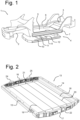
- Figure 1 shows a frame 1 of an electric vehicle comprising a body-in-white front frame structure 2, a body-in-white rear floor structure 3, including set or rockers and a structural battery assembly 4 forming a bottom structure 5 of the vehicle.
- the structural battery assembly 4 comprises longitudinal sill profiles 6,7 that interconnect the front and rear frame structures 2,3 and that support a battery pack 9 of interconnected battery cells.
- Cross beams 11, 12 are connected, for instance via spot welding, to a top plate 10 of the battery pack 9 and extend in a transverse direction, interconnecting the sill profiles 6,7 and supporting front passenger seats.
- Figure 2 shows a tray 13 of the battery pack 9, having longitudinal side member 14,15 that are interconnected by front transverse beam 16 and rear and transverse beam 17.
- a metal bottom plate 18 with longitudinal cooling channels 19, 20 forms the bottom of the tray 13.
- a cooling inlet manifold 21 distributes cooling fluid to the channels 19,20 and an outlet manifold 22 at the rear removes the heated coolant from the channels and transports it to a heat exchanger.
- connecting brackets 24, 25 are provided for providing a rigid connection of the tray 13 to the front frame structure 2.
- FIG. 3 shows a battery frame structure 30 carrying four rows 31-34 of battery cells. Each individual cell is placed in a cavity 35, 36 of the battery frame structure 30 and is firmly held in place by a bonding substance that fills up the space between the walls of the cavities 35, 36 and the cell inside the cavity.
- the battery frame structure 30 has longitudinal and transverse peripheral walls 37, 38 and forms a matrix of interconnected battery cells that can be handled as a unit and that can be accurately positioned in the tray 13.
- the height of the peripheral walls 37, 38 and of the cavity walls substantially corresponds to the height of the battery cells 31-34, so that the top and bottom surfaces of the assembly of battery frame structure 30 and cells 31-34 is substantially planar.
- Figure 4 shows an enlarged detail of the battery frame structure 30 near the front transverse beam 16.
- the cells 39, 40 are enclosed within the walls 38,37,43, 44 and 37,43,44,45 of respective cavities of the battery frame structure.
- the gaps 41 and 42 between the cells 39, 40 and the cavity walls are filled with a bonding material, that may be formed by an adhesive material or an expanding compound that can flow and fill the gaps and that can expand and solidify to firmly bond the cells to the cavity walls.
- the expanding compound could provide a pre-compression on the individual battery cells.
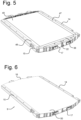
- Figure 5 shows an adhesive layer 49 that is placed on top of the battery cells in the battery frame structure 30.
- the space between the longitudinal side members 14, 15 and the longitudinal peripheral walls 37 of the battery frame structure 30 is filled with a foam block or honeycomb structure.
- the battery pack 9 is completed by placing a metal top cover 50 over the battery frame structure 30 and attaching the top cover to the adhesive layer 49 and to the side members 14,15 to form a strong casing around the battery cells.
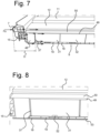
- Figure 7 shows the battery pack 9 connected to the sill profiles 6,7 and to the cross beams 11,12.
- the transverse forces Fs are distributed along the longitudinal side member 15 to the shear planes that are defined by the lower plate 18 and upper plate of the top cover 50.
- a deformation zone with a transverse width D is formed by the sill profile 7, the side member 15 and the foam block or honeycomb material 48. The deformation zone protects the battery cells 31-34 upon side impact and prevents rupture of the cells and intrusion upon impact.
- Figure 8 shows an enlarged detail of a longitudinal venting channel 52 extending in a length direction over the cooling channels 19 in the bottom plate 18.
- gases are evacuated through the venting channel 52 to the rear transverse beam 17, where the gases can escape to environment. Because the venting channel 52 is cooled by the cooling channels 19 in the cooling plate, the risk of burn-through is significantly reduced.
- a replaceable insulation layer 53 can be provided over the cooling plate to form the outer layer of the vehicle.
- the thermal isolation provided by the layer 53 mitigates the wind chill factor of the battery pack 9 by the environment and prevents uncontrolled heat transfer.
- the insulation layer 53 gets damaged, for instance in case of a de-road accident, it can be easily removed, inspected and serviced or replaced.
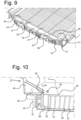
- Figure 9 shows a reinforcement metal end plate 55 that is attached to the transverse wall 38 of the battery frame structure and to the front transverse beam 16, via anchor brackets 56, 57.
- the reinforcement end plate 55 can counteract swelling of the battery cells upon ageing which may cause forces on the sidewalls of the transverse peripheral walls 38 of the battery frame structure 30 of 10-30 kN.
- Figure 10 shows a front frame part 65 of the vehicle that is attached via bolts 60,61 to the anchor bracket 56, and via a bolt 62 to the bracket 24 on the front transverse beam 16.
- the frontal impact force F f is deflected downward to the anchor bracket 56.
- the anchor bracket 56 is arc welded to the end plate 55, and has a number of bonded shear planes that distribute the load across the surface of the anchor bracket across the end plate 55 thereby keeping intrusions of the battery cells in the battery frame structure within safe limits.
Landscapes
- Chemical & Material Sciences (AREA)
- Chemical Kinetics & Catalysis (AREA)
- Electrochemistry (AREA)
- General Chemical & Material Sciences (AREA)
- Engineering & Computer Science (AREA)
- Manufacturing & Machinery (AREA)
- Aviation & Aerospace Engineering (AREA)
- Mechanical Engineering (AREA)
- Transportation (AREA)
- Sustainable Development (AREA)
- Sustainable Energy (AREA)
- Power Engineering (AREA)
- Life Sciences & Earth Sciences (AREA)
- Combustion & Propulsion (AREA)
- Arrangement Or Mounting Of Propulsion Units For Vehicles (AREA)
- Battery Mounting, Suspending (AREA)
Claims (15)
- Elektrofahrzeug, umfassend eine Batterieanordnung (4) mit mindestens zwei Reihen (31-34) von Batteriezellen (39, 40), die an einer Batterierahmenstruktur (30) angebracht sind, dadurch gekennzeichnet, dass die Batterierahmenstruktur eine Anzahl von Aufnahmehohlräumen (35, 36), die in einer Matrix angeordnet sind, umfasst, wobei jede Batteriezelle (39, 40) in einem jeweiligen Aufnahmehohlraum (35, 36) platziert ist, dadurch gekennzeichnet, dass jede Batteriezelle (39, 40) mit benachbarten Wänden (43, 44, 45) des jeweiligen Aufnahmehohlraums (35, 36) über eine fließfähige Bondungssubstanz, die in einen Spalt (41, 42) zwischen den Zellen und den Wänden (43, 44, 45) des jeweiligen Hohlraums eingefügt ist, verbunden ist.
- Elektrofahrzeug nach Anspruch 1, wobei die Batterierahmenstruktur (30) Längs- und Querumfangswände (37, 38) umfasst, wobei die Umfangswände und die Wände der Aufnahmehohlräume (43-45) durch Spritzgießen, Gießen oder additive Fertigung aus einem ersten, sich verfestigenden Material gebildet sind, wobei die fließfähige Bondungssubstanz eine zweite Substanz umfasst.
- Elektrofahrzeug nach Anspruch 1 oder 2, wobei die Aufnahmehohlräume (35, 36) von im Wesentlichen der gleichen Höhe wie eine Höhe der Batteriezellen (39, 40) sind, wobei eine Unterseite der Batterierahmenstruktur (30) im Wesentlichen flach ist und eine wärmeleitfähige Schicht stützt, die den Boden jeder Batteriezelle (39, 40) kontaktiert, wobei eine Oberseite der Batterierahmenstruktur (30) in einer kontaktierenden Beziehung mit einer oberen Abdeckung (49, 50) platziert ist.
- Elektrofahrzeug nach einem der vorangehenden Ansprüche, wobei die Batterierahmenstruktur (30) in einem Schalenelement (13) platziert ist, das zwei Längsseitenprofile (14, 15) umfasst, die über eine vordere und eine hintere Traverse (16, 17) miteinander verbunden sind, wobei sich Längsumfangswände (37) der Batterierahmenstruktur (30) in einer Distanz von den Längsseitenprofilen (15, 16) erstrecken, wobei ein komprimierbares Füllerelement (47, 48) zwischen den Längsumfangswänden (37) der Batterierahmenstruktur (30) und dem jeweiligen benachbarten Längsseitenprofil (14, 15) platziert ist.
- Elektrofahrzeug nach Anspruch 4, wobei eine obere Platte (50) und eine untere Platte (18) in Kontakt mit der oberen und der unteren Ebene der Batterierahmenstruktur (30) platziert sind, wobei die obere und die untere Platte (50, 18) an den Längsseitenprofilen (14, 15) angebracht sind und ein Gehäuse bilden.
- Elektrofahrzeug nach Anspruch 4 oder 5, wobei die untere Platte (18) eine Anzahl von Kühlkanälen (19, 20) umfasst, die sich in einer Längsrichtung erstrecken, wobei die Kühlkanäle an einer ersten Traverse (16) mit einem Kühlfluideinlass (21) verbunden sind und an einer zweiten Traverse (17) mit einem Kühlfluidauslassverteiler (22) verbunden sind.
- Elektrofahrzeug nach Anspruch 6, wobei die untere Platte (18) durch eine Isolierschicht (53) bedeckt ist, die die äußere Bodenschicht des Fahrzeugs bildet.
- Elektrofahrzeug nach Anspruch 5, 6 oder 7, wobei die vordere und die hintere Umfangswand (38) der Batterierahmenstruktur (30) eine jeweilige parallele metallische Verstärkungsplatte (55) kontaktieren, die die vordere und die hintere Umfangswand (38) kontaktiert und entlang ihrer Breite mit der vorderen und der hinteren Traverse (16, 17) verbunden ist.
- Elektrofahrzeug nach Anspruch 8, wobei die vordere Verstärkungsplatte (50) ein mittig platziertes, bevorzugt durch Extrusion gebildetes Verstärkungselement (56) umfasst, das eine Anzahl von Fächern aufweist.
- Batterieanordnung (4) zur Verwendung in einem Elektrofahrzeug, umfassend mindestens zwei Reihen (31-34) von Batteriezellen (39, 40), die an einer Batterierahmenstruktur (30) mit einer Anzahl von Aufnahmehohlräumen (35, 36), die in einer Matrix angeordnet sind, angebracht sind, wobei jede Batteriezelle (39, 40) in einem jeweiligen Aufnahmehohlraum (35, 36) platziert ist, dadurch gekennzeichnet, dass jede Batteriezelle (39, 40) mit benachbarten Wänden (43, 44, 45) des jeweiligen Aufnahmehohlraums (35, 36) über eine fließfähige Bondungssubstanz, die in einen Spalt (41, 42) zwischen den Zellen (39, 40) und den Wänden (43-45) des jeweiligen Hohlraums (35, 36) eingefügt ist, verbunden ist.
- Batterieanordnung (4) nach Anspruch 10, wobei die Batterierahmenstruktur (30) in einem Schalenelement (13) platziert ist, das zwei Längsseitenprofile (14, 15) umfasst, die über eine vordere und eine hintere Traverse (16, 17) miteinander verbunden sind, wobei sich Längsumfangswände (37) der Batterierahmenstruktur (30) in einer Distanz von den Längsseitenprofilen (14, 15) erstrecken, wobei ein komprimierbares Füllerelement (47, 48) zwischen den Längsumfangswänden (37) der Batterierahmenstruktur (30) und dem benachbarten Längsseitenprofil (14, 15) platziert ist.
- Verfahren zum Herstellen einer Batterieanordnung (4) für ein Elektrofahrzeug, umfassend:- Bilden einer Batterierahmenstruktur (30), die Längs- und Querumfangswände (37, 38) aufweist und eine Anzahl von Aufnahmehohlräumen (35, 36), die in einer Matrix angeordnet sind, umfasst, durch Spritzgießen, Gießen oder additive Fertigung,- Einsetzen von Batteriezellen (39, 40) in die Aufnahmehohlräume, wobei die Batteriezellen (39, 40) in mindestens zwei Reihen (31, 34) von Batteriezellen (39, 40) eingesetzt werden, und gekennzeichnet durch:- Auffüllen eines Spalts (41, 42) zwischen den Zellen und den Wänden (43, 44, 45) des jeweiligen Hohlraums mit einem Bondungsmaterial, wodurch jede Batteriezelle (39, 40) mit den Wänden (43, 44, 45) des jeweiligen Hohlraums über das Bondungsmaterial verbunden wird, wodurch ein unitärer Zellenblock gebildet wird.
- Verfahren nach Anspruch 12, des Weiteren umfassend:- Platzieren des durch die Batterierahmenstruktur (30) und die verbundenen Batteriezellen (39, 40) gebildeten unitären Zellenblocks in ein Schalenelement (13), das zwei Längsseitenprofile (14, 15) umfasst, die über eine vordere und eine hintere Traverse (16, 17) miteinander verbunden sind, wobei sich die Längsumfangswände (37) der Batterierahmenstruktur (30) in einer Distanz von den Längsseitenprofilen (14, 15) erstrecken,- Einsetzen eines verformbaren Elements zwischen die Längsumfangswände (37) der Batterierahmenstruktur (30) und das benachbarte Längsseitenprofil (14, 15),- Platzieren einer oberen Platte (50) und einer unteren Platte (18) an der Ober- und der Unterseite der Batterierahmenstruktur (30).
- Verfahren nach Anspruch 13, umfassend das Anbringen der oberen und der unteren Platte (18, 50) an einem Fahrzeugrahmen.
- Verfahren nach Anspruch 13 oder 14, umfassend das Verbinden der oberen und der unteren Platte (18, 50) mit Längsseitenprofilen (14, 15), wodurch ein Gehäuse gebildet wird.
Priority Applications (3)
| Application Number | Priority Date | Filing Date | Title |
|---|---|---|---|
| EP21186240.4A EP4120435B1 (de) | 2021-07-16 | 2021-07-16 | Strukturbatterie für ein elektrofahrzeug mit einer batteriezellenträgermatrix |
| US17/861,319 US12597667B2 (en) | 2021-07-16 | 2022-07-11 | Structural battery for an electric vehicle comprising a battery cell support matrix |
| CN202210842792.1A CN115621603A (zh) | 2021-07-16 | 2022-07-18 | 包括电池的电池单元支撑矩阵的电动车辆的结构电池 |
Applications Claiming Priority (1)
| Application Number | Priority Date | Filing Date | Title |
|---|---|---|---|
| EP21186240.4A EP4120435B1 (de) | 2021-07-16 | 2021-07-16 | Strukturbatterie für ein elektrofahrzeug mit einer batteriezellenträgermatrix |
Publications (2)
| Publication Number | Publication Date |
|---|---|
| EP4120435A1 EP4120435A1 (de) | 2023-01-18 |
| EP4120435B1 true EP4120435B1 (de) | 2025-06-18 |
Family
ID=76958881
Family Applications (1)
| Application Number | Title | Priority Date | Filing Date |
|---|---|---|---|
| EP21186240.4A Active EP4120435B1 (de) | 2021-07-16 | 2021-07-16 | Strukturbatterie für ein elektrofahrzeug mit einer batteriezellenträgermatrix |
Country Status (3)
| Country | Link |
|---|---|
| US (1) | US12597667B2 (de) |
| EP (1) | EP4120435B1 (de) |
| CN (1) | CN115621603A (de) |
Families Citing this family (8)
| Publication number | Priority date | Publication date | Assignee | Title |
|---|---|---|---|---|
| PL3119218T3 (pl) * | 2014-03-19 | 2020-05-18 | Philip Morris Products S.A. | Płaszczyzna monolityczna ze stykami elektrycznymi i sposoby wytwarzania |
| EP4468451B1 (de) * | 2023-05-23 | 2025-07-23 | Röchling Automotive SE | Batteriepack |
| CN116487809B (zh) * | 2023-06-25 | 2023-09-15 | 北京玖行智研交通科技有限公司 | 动力电池组件、动力电池箱总成及换电车辆 |
| FI131750B1 (en) * | 2023-06-28 | 2025-11-07 | Avant Tecno Oy | Battery pack |
| CN120237327A (zh) * | 2023-12-29 | 2025-07-01 | 浙江吉利控股集团有限公司 | 电池托盘及电池组件 |
| US20250293370A1 (en) * | 2024-03-13 | 2025-09-18 | Fisker Inc. | Body-integrated vehicle battery box sub assembly |
| DE102024109065A1 (de) * | 2024-03-28 | 2025-10-02 | Webasto SE | Batterie und Batteriesystem für ein Kraftfahrzeug |
| EP4679596A1 (de) * | 2024-07-09 | 2026-01-14 | Volvo Car Corporation | Batterieanordnung für ein fahrzeug, unterbodenstruktur für ein fahrzeug, fahrzeug und verfahren |
Family Cites Families (10)
| Publication number | Priority date | Publication date | Assignee | Title |
|---|---|---|---|---|
| CN106058100B (zh) * | 2012-09-06 | 2018-11-13 | 阿提瓦公司 | 框架具有点胶挡止的电池组件 |
| KR101649154B1 (ko) * | 2014-02-24 | 2016-08-18 | 엘지전자 주식회사 | 공기유로를 가지는 배터리팩 |
| US20180105062A1 (en) * | 2016-10-14 | 2018-04-19 | Inevit, Inc. | Battery module compartment chamber and battery module mounting area of an energy storage system and method thereof |
| DE102017204412A1 (de) | 2017-03-16 | 2018-09-20 | Audi Ag | Batterie für ein Kraftfahrzeug und Kraftfahrzeug |
| JP7325014B2 (ja) | 2018-03-27 | 2023-08-14 | パナソニックIpマネジメント株式会社 | 蓄電モジュール |
| EP3584877A1 (de) | 2018-05-16 | 2019-12-25 | Samsung SDI Co., Ltd. | Batteriepack mit einem rahmenprofil mit integralen kühlkreislaufelementen |
| KR102585988B1 (ko) | 2018-06-20 | 2023-10-05 | 주식회사 엘지에너지솔루션 | 배터리 모듈, 이러한 배터리 모듈을 포함하는 배터리 팩 및 이러한 배터리 팩을 포함하는 자동차 |
| GB2578738B (en) * | 2018-11-05 | 2020-12-09 | Xerotech Ltd | Thermal management system for a battery |
| DE102019220260A1 (de) * | 2019-12-19 | 2021-06-24 | Volkswagen Aktiengesellschaft | Hochvoltbatterie für ein Fahrzeug |
| KR102924317B1 (ko) * | 2019-12-31 | 2026-02-05 | 삼성에스디아이 주식회사 | 배터리 팩 |
-
2021
- 2021-07-16 EP EP21186240.4A patent/EP4120435B1/de active Active
-
2022
- 2022-07-11 US US17/861,319 patent/US12597667B2/en active Active
- 2022-07-18 CN CN202210842792.1A patent/CN115621603A/zh active Pending
Also Published As
| Publication number | Publication date |
|---|---|
| CN115621603A (zh) | 2023-01-17 |
| EP4120435A1 (de) | 2023-01-18 |
| US12597667B2 (en) | 2026-04-07 |
| US20230022211A1 (en) | 2023-01-26 |
Similar Documents
| Publication | Publication Date | Title |
|---|---|---|
| EP4120435B1 (de) | Strukturbatterie für ein elektrofahrzeug mit einer batteriezellenträgermatrix | |
| JP7598375B2 (ja) | 統合されたエネルギー貯蔵システム | |
| US11376941B2 (en) | Electric vehicle battery cooling structure | |
| JP7339565B2 (ja) | 自動車の下部構造 | |
| JP2024528652A (ja) | 自動車用の駆動バッテリおよびそのような駆動バッテリを備えた自動車 | |
| CN116890625A (zh) | 车辆 | |
| CN117546350A (zh) | 用于机动车的驱动电池和具有这种驱动电池的机动车 | |
| CN118843553A (zh) | 电蓄能器在乘用车的车身壳体上的布置结构 | |
| US12230775B2 (en) | Battery packs with safety features and methods of installing such packs on truck frames | |
| CN212113791U (zh) | 一种软包电芯的成组结构电池包 | |
| US20230025278A1 (en) | Structural Battery With Reduced Sill Height | |
| CN113745699B (zh) | 轻量化电池包托盘集成结构 | |
| US12358359B2 (en) | Structural battery for an electric vehicle | |
| EP4231399A1 (de) | Strukturelles batteriepackzellensignal und umwandlungsdurchführung | |
| US20250192335A1 (en) | Traction battery pack barrier assembly | |
| CN218569054U (zh) | 一种电池包下箱体、电池包及电动装置 | |
| CN220510155U (zh) | 一种复合式电池包托盘 | |
| US12415411B2 (en) | Structural battery for an electric vehicle and method of manufacturing | |
| CN114590115B (zh) | 车辆 | |
| JP2026016295A (ja) | 集積型電池パック及び電気自動車 | |
| HK40072584A (en) | Vehicle | |
| CN117219941A (zh) | 电池模组、电池和车辆 | |
| WO2023175354A1 (en) | Monocoque vehicle, structured battery and method of manufacture |
Legal Events
| Date | Code | Title | Description |
|---|---|---|---|
| PUAI | Public reference made under article 153(3) epc to a published international application that has entered the european phase |
Free format text: ORIGINAL CODE: 0009012 |
|
| STAA | Information on the status of an ep patent application or granted ep patent |
Free format text: STATUS: THE APPLICATION HAS BEEN PUBLISHED |
|
| AK | Designated contracting states |
Kind code of ref document: A1 Designated state(s): AL AT BE BG CH CY CZ DE DK EE ES FI FR GB GR HR HU IE IS IT LI LT LU LV MC MK MT NL NO PL PT RO RS SE SI SK SM TR |
|
| STAA | Information on the status of an ep patent application or granted ep patent |
Free format text: STATUS: REQUEST FOR EXAMINATION WAS MADE |
|
| 17P | Request for examination filed |
Effective date: 20230314 |
|
| RBV | Designated contracting states (corrected) |
Designated state(s): AL AT BE BG CH CY CZ DE DK EE ES FI FR GB GR HR HU IE IS IT LI LT LU LV MC MK MT NL NO PL PT RO RS SE SI SK SM TR |
|
| GRAP | Despatch of communication of intention to grant a patent |
Free format text: ORIGINAL CODE: EPIDOSNIGR1 |
|
| STAA | Information on the status of an ep patent application or granted ep patent |
Free format text: STATUS: GRANT OF PATENT IS INTENDED |
|
| INTG | Intention to grant announced |
Effective date: 20250203 |
|
| GRAS | Grant fee paid |
Free format text: ORIGINAL CODE: EPIDOSNIGR3 |
|
| GRAA | (expected) grant |
Free format text: ORIGINAL CODE: 0009210 |
|
| STAA | Information on the status of an ep patent application or granted ep patent |
Free format text: STATUS: THE PATENT HAS BEEN GRANTED |
|
| AK | Designated contracting states |
Kind code of ref document: B1 Designated state(s): AL AT BE BG CH CY CZ DE DK EE ES FI FR GB GR HR HU IE IS IT LI LT LU LV MC MK MT NL NO PL PT RO RS SE SI SK SM TR |
|
| REG | Reference to a national code |
Ref country code: GB Ref legal event code: FG4D |
|
| RIN1 | Information on inventor provided before grant (corrected) |
Inventor name: HJAELM WALLBORG, MARTIN Inventor name: PERSSON, KLAS Inventor name: KARLSSON, DANIEL |
|
| REG | Reference to a national code |
Ref country code: CH Ref legal event code: EP |
|
| REG | Reference to a national code |
Ref country code: DE Ref legal event code: R096 Ref document number: 602021032348 Country of ref document: DE |
|
| REG | Reference to a national code |
Ref country code: CH Ref legal event code: EP |
|
| P01 | Opt-out of the competence of the unified patent court (upc) registered |
Free format text: CASE NUMBER: APP_26726/2025 Effective date: 20250605 |
|
| REG | Reference to a national code |
Ref country code: IE Ref legal event code: FG4D |
|
| PG25 | Lapsed in a contracting state [announced via postgrant information from national office to epo] |
Ref country code: FI Free format text: LAPSE BECAUSE OF FAILURE TO SUBMIT A TRANSLATION OF THE DESCRIPTION OR TO PAY THE FEE WITHIN THE PRESCRIBED TIME-LIMIT Effective date: 20250618 |
|
| PGFP | Annual fee paid to national office [announced via postgrant information from national office to epo] |
Ref country code: DE Payment date: 20250724 Year of fee payment: 5 |
|
| REG | Reference to a national code |
Ref country code: LT Ref legal event code: MG9D |
|
| PG25 | Lapsed in a contracting state [announced via postgrant information from national office to epo] |
Ref country code: GR Free format text: LAPSE BECAUSE OF FAILURE TO SUBMIT A TRANSLATION OF THE DESCRIPTION OR TO PAY THE FEE WITHIN THE PRESCRIBED TIME-LIMIT Effective date: 20250919 Ref country code: NO Free format text: LAPSE BECAUSE OF FAILURE TO SUBMIT A TRANSLATION OF THE DESCRIPTION OR TO PAY THE FEE WITHIN THE PRESCRIBED TIME-LIMIT Effective date: 20250918 |
|
| PG25 | Lapsed in a contracting state [announced via postgrant information from national office to epo] |
Ref country code: BG Free format text: LAPSE BECAUSE OF FAILURE TO SUBMIT A TRANSLATION OF THE DESCRIPTION OR TO PAY THE FEE WITHIN THE PRESCRIBED TIME-LIMIT Effective date: 20250618 |
|
| PGFP | Annual fee paid to national office [announced via postgrant information from national office to epo] |
Ref country code: GB Payment date: 20250724 Year of fee payment: 5 |
|
| PG25 | Lapsed in a contracting state [announced via postgrant information from national office to epo] |
Ref country code: HR Free format text: LAPSE BECAUSE OF FAILURE TO SUBMIT A TRANSLATION OF THE DESCRIPTION OR TO PAY THE FEE WITHIN THE PRESCRIBED TIME-LIMIT Effective date: 20250618 |
|
| PGFP | Annual fee paid to national office [announced via postgrant information from national office to epo] |
Ref country code: AT Payment date: 20251020 Year of fee payment: 5 Ref country code: FR Payment date: 20250723 Year of fee payment: 5 |
|
| PG25 | Lapsed in a contracting state [announced via postgrant information from national office to epo] |
Ref country code: RS Free format text: LAPSE BECAUSE OF FAILURE TO SUBMIT A TRANSLATION OF THE DESCRIPTION OR TO PAY THE FEE WITHIN THE PRESCRIBED TIME-LIMIT Effective date: 20250918 |
|
| REG | Reference to a national code |
Ref country code: NL Ref legal event code: MP Effective date: 20250618 |
|
| PG25 | Lapsed in a contracting state [announced via postgrant information from national office to epo] |
Ref country code: LV Free format text: LAPSE BECAUSE OF FAILURE TO SUBMIT A TRANSLATION OF THE DESCRIPTION OR TO PAY THE FEE WITHIN THE PRESCRIBED TIME-LIMIT Effective date: 20250618 |
|
| PG25 | Lapsed in a contracting state [announced via postgrant information from national office to epo] |
Ref country code: NL Free format text: LAPSE BECAUSE OF FAILURE TO SUBMIT A TRANSLATION OF THE DESCRIPTION OR TO PAY THE FEE WITHIN THE PRESCRIBED TIME-LIMIT Effective date: 20250618 |
|
| PG25 | Lapsed in a contracting state [announced via postgrant information from national office to epo] |
Ref country code: PT Free format text: LAPSE BECAUSE OF FAILURE TO SUBMIT A TRANSLATION OF THE DESCRIPTION OR TO PAY THE FEE WITHIN THE PRESCRIBED TIME-LIMIT Effective date: 20251020 |
|
| REG | Reference to a national code |
Ref country code: AT Ref legal event code: MK05 Ref document number: 1805080 Country of ref document: AT Kind code of ref document: T Effective date: 20250618 |
|
| PG25 | Lapsed in a contracting state [announced via postgrant information from national office to epo] |
Ref country code: IS Free format text: LAPSE BECAUSE OF FAILURE TO SUBMIT A TRANSLATION OF THE DESCRIPTION OR TO PAY THE FEE WITHIN THE PRESCRIBED TIME-LIMIT Effective date: 20251018 |
|
| PG25 | Lapsed in a contracting state [announced via postgrant information from national office to epo] |
Ref country code: SM Free format text: LAPSE BECAUSE OF FAILURE TO SUBMIT A TRANSLATION OF THE DESCRIPTION OR TO PAY THE FEE WITHIN THE PRESCRIBED TIME-LIMIT Effective date: 20250618 Ref country code: AT Free format text: LAPSE BECAUSE OF FAILURE TO SUBMIT A TRANSLATION OF THE DESCRIPTION OR TO PAY THE FEE WITHIN THE PRESCRIBED TIME-LIMIT Effective date: 20250618 |
|
| PG25 | Lapsed in a contracting state [announced via postgrant information from national office to epo] |
Ref country code: CZ Free format text: LAPSE BECAUSE OF FAILURE TO SUBMIT A TRANSLATION OF THE DESCRIPTION OR TO PAY THE FEE WITHIN THE PRESCRIBED TIME-LIMIT Effective date: 20250618 |
|
| PG25 | Lapsed in a contracting state [announced via postgrant information from national office to epo] |
Ref country code: PL Free format text: LAPSE BECAUSE OF FAILURE TO SUBMIT A TRANSLATION OF THE DESCRIPTION OR TO PAY THE FEE WITHIN THE PRESCRIBED TIME-LIMIT Effective date: 20250618 |
|
| PG25 | Lapsed in a contracting state [announced via postgrant information from national office to epo] |
Ref country code: EE Free format text: LAPSE BECAUSE OF FAILURE TO SUBMIT A TRANSLATION OF THE DESCRIPTION OR TO PAY THE FEE WITHIN THE PRESCRIBED TIME-LIMIT Effective date: 20250618 |
|
| PG25 | Lapsed in a contracting state [announced via postgrant information from national office to epo] |
Ref country code: SK Free format text: LAPSE BECAUSE OF FAILURE TO SUBMIT A TRANSLATION OF THE DESCRIPTION OR TO PAY THE FEE WITHIN THE PRESCRIBED TIME-LIMIT Effective date: 20250618 |
|
| PG25 | Lapsed in a contracting state [announced via postgrant information from national office to epo] |
Ref country code: ES Free format text: LAPSE BECAUSE OF FAILURE TO SUBMIT A TRANSLATION OF THE DESCRIPTION OR TO PAY THE FEE WITHIN THE PRESCRIBED TIME-LIMIT Effective date: 20250618 |
|
| PG25 | Lapsed in a contracting state [announced via postgrant information from national office to epo] |
Ref country code: RO Free format text: LAPSE BECAUSE OF FAILURE TO SUBMIT A TRANSLATION OF THE DESCRIPTION OR TO PAY THE FEE WITHIN THE PRESCRIBED TIME-LIMIT Effective date: 20250618 |
|
| REG | Reference to a national code |
Ref country code: CH Ref legal event code: H13 Free format text: ST27 STATUS EVENT CODE: U-0-0-H10-H13 (AS PROVIDED BY THE NATIONAL OFFICE) Effective date: 20260224 |
|
| PG25 | Lapsed in a contracting state [announced via postgrant information from national office to epo] |
Ref country code: LU Free format text: LAPSE BECAUSE OF NON-PAYMENT OF DUE FEES Effective date: 20250716 |
|
| REG | Reference to a national code |
Ref country code: BE Ref legal event code: MM Effective date: 20250731 |
|
| PG25 | Lapsed in a contracting state [announced via postgrant information from national office to epo] |
Ref country code: MC Free format text: LAPSE BECAUSE OF FAILURE TO SUBMIT A TRANSLATION OF THE DESCRIPTION OR TO PAY THE FEE WITHIN THE PRESCRIBED TIME-LIMIT Effective date: 20250618 |
|
| PG25 | Lapsed in a contracting state [announced via postgrant information from national office to epo] |
Ref country code: DK Free format text: LAPSE BECAUSE OF FAILURE TO SUBMIT A TRANSLATION OF THE DESCRIPTION OR TO PAY THE FEE WITHIN THE PRESCRIBED TIME-LIMIT Effective date: 20250618 |
|
| PG25 | Lapsed in a contracting state [announced via postgrant information from national office to epo] |
Ref country code: IT Free format text: LAPSE BECAUSE OF FAILURE TO SUBMIT A TRANSLATION OF THE DESCRIPTION OR TO PAY THE FEE WITHIN THE PRESCRIBED TIME-LIMIT Effective date: 20250618 Ref country code: BE Free format text: LAPSE BECAUSE OF NON-PAYMENT OF DUE FEES Effective date: 20250731 |
|
| PLBE | No opposition filed within time limit |
Free format text: ORIGINAL CODE: 0009261 |
|
| STAA | Information on the status of an ep patent application or granted ep patent |
Free format text: STATUS: NO OPPOSITION FILED WITHIN TIME LIMIT |