EP4120435A1 - Structural battery for an electric vehicle comprising a battery cell support matrix - Google Patents
Structural battery for an electric vehicle comprising a battery cell support matrix Download PDFInfo
- Publication number
- EP4120435A1 EP4120435A1 EP21186240.4A EP21186240A EP4120435A1 EP 4120435 A1 EP4120435 A1 EP 4120435A1 EP 21186240 A EP21186240 A EP 21186240A EP 4120435 A1 EP4120435 A1 EP 4120435A1
- Authority
- EP
- European Patent Office
- Prior art keywords
- battery
- frame structure
- battery frame
- electric vehicle
- walls
- Prior art date
- Legal status (The legal status is an assumption and is not a legal conclusion. Google has not performed a legal analysis and makes no representation as to the accuracy of the status listed.)
- Pending
Links
Images

Classifications
-
- H—ELECTRICITY
- H01—ELECTRIC ELEMENTS
- H01M—PROCESSES OR MEANS, e.g. BATTERIES, FOR THE DIRECT CONVERSION OF CHEMICAL ENERGY INTO ELECTRICAL ENERGY
- H01M50/00—Constructional details or processes of manufacture of the non-active parts of electrochemical cells other than fuel cells, e.g. hybrid cells
- H01M50/20—Mountings; Secondary casings or frames; Racks, modules or packs; Suspension devices; Shock absorbers; Transport or carrying devices; Holders
- H01M50/249—Mountings; Secondary casings or frames; Racks, modules or packs; Suspension devices; Shock absorbers; Transport or carrying devices; Holders specially adapted for aircraft or vehicles, e.g. cars or trains
-
- B—PERFORMING OPERATIONS; TRANSPORTING
- B60—VEHICLES IN GENERAL
- B60K—ARRANGEMENT OR MOUNTING OF PROPULSION UNITS OR OF TRANSMISSIONS IN VEHICLES; ARRANGEMENT OR MOUNTING OF PLURAL DIVERSE PRIME-MOVERS IN VEHICLES; AUXILIARY DRIVES FOR VEHICLES; INSTRUMENTATION OR DASHBOARDS FOR VEHICLES; ARRANGEMENTS IN CONNECTION WITH COOLING, AIR INTAKE, GAS EXHAUST OR FUEL SUPPLY OF PROPULSION UNITS IN VEHICLES
- B60K1/00—Arrangement or mounting of electrical propulsion units
- B60K1/04—Arrangement or mounting of electrical propulsion units of the electric storage means for propulsion
-
- B—PERFORMING OPERATIONS; TRANSPORTING
- B60—VEHICLES IN GENERAL
- B60L—PROPULSION OF ELECTRICALLY-PROPELLED VEHICLES; SUPPLYING ELECTRIC POWER FOR AUXILIARY EQUIPMENT OF ELECTRICALLY-PROPELLED VEHICLES; ELECTRODYNAMIC BRAKE SYSTEMS FOR VEHICLES IN GENERAL; MAGNETIC SUSPENSION OR LEVITATION FOR VEHICLES; MONITORING OPERATING VARIABLES OF ELECTRICALLY-PROPELLED VEHICLES; ELECTRIC SAFETY DEVICES FOR ELECTRICALLY-PROPELLED VEHICLES
- B60L50/00—Electric propulsion with power supplied within the vehicle
- B60L50/50—Electric propulsion with power supplied within the vehicle using propulsion power supplied by batteries or fuel cells
- B60L50/60—Electric propulsion with power supplied within the vehicle using propulsion power supplied by batteries or fuel cells using power supplied by batteries
- B60L50/64—Constructional details of batteries specially adapted for electric vehicles
-
- H—ELECTRICITY
- H01—ELECTRIC ELEMENTS
- H01M—PROCESSES OR MEANS, e.g. BATTERIES, FOR THE DIRECT CONVERSION OF CHEMICAL ENERGY INTO ELECTRICAL ENERGY
- H01M10/00—Secondary cells; Manufacture thereof
- H01M10/60—Heating or cooling; Temperature control
- H01M10/61—Types of temperature control
- H01M10/613—Cooling or keeping cold
-
- H—ELECTRICITY
- H01—ELECTRIC ELEMENTS
- H01M—PROCESSES OR MEANS, e.g. BATTERIES, FOR THE DIRECT CONVERSION OF CHEMICAL ENERGY INTO ELECTRICAL ENERGY
- H01M10/00—Secondary cells; Manufacture thereof
- H01M10/60—Heating or cooling; Temperature control
- H01M10/62—Heating or cooling; Temperature control specially adapted for specific applications
- H01M10/625—Vehicles
-
- H—ELECTRICITY
- H01—ELECTRIC ELEMENTS
- H01M—PROCESSES OR MEANS, e.g. BATTERIES, FOR THE DIRECT CONVERSION OF CHEMICAL ENERGY INTO ELECTRICAL ENERGY
- H01M10/00—Secondary cells; Manufacture thereof
- H01M10/60—Heating or cooling; Temperature control
- H01M10/64—Heating or cooling; Temperature control characterised by the shape of the cells
- H01M10/647—Prismatic or flat cells, e.g. pouch cells
-
- H—ELECTRICITY
- H01—ELECTRIC ELEMENTS
- H01M—PROCESSES OR MEANS, e.g. BATTERIES, FOR THE DIRECT CONVERSION OF CHEMICAL ENERGY INTO ELECTRICAL ENERGY
- H01M10/00—Secondary cells; Manufacture thereof
- H01M10/60—Heating or cooling; Temperature control
- H01M10/65—Means for temperature control structurally associated with the cells
- H01M10/653—Means for temperature control structurally associated with the cells characterised by electrically insulating or thermally conductive materials
-
- H—ELECTRICITY
- H01—ELECTRIC ELEMENTS
- H01M—PROCESSES OR MEANS, e.g. BATTERIES, FOR THE DIRECT CONVERSION OF CHEMICAL ENERGY INTO ELECTRICAL ENERGY
- H01M10/00—Secondary cells; Manufacture thereof
- H01M10/60—Heating or cooling; Temperature control
- H01M10/65—Means for temperature control structurally associated with the cells
- H01M10/655—Solid structures for heat exchange or heat conduction
- H01M10/6554—Rods or plates
-
- H—ELECTRICITY
- H01—ELECTRIC ELEMENTS
- H01M—PROCESSES OR MEANS, e.g. BATTERIES, FOR THE DIRECT CONVERSION OF CHEMICAL ENERGY INTO ELECTRICAL ENERGY
- H01M10/00—Secondary cells; Manufacture thereof
- H01M10/60—Heating or cooling; Temperature control
- H01M10/65—Means for temperature control structurally associated with the cells
- H01M10/655—Solid structures for heat exchange or heat conduction
- H01M10/6556—Solid parts with flow channel passages or pipes for heat exchange
-
- H—ELECTRICITY
- H01—ELECTRIC ELEMENTS
- H01M—PROCESSES OR MEANS, e.g. BATTERIES, FOR THE DIRECT CONVERSION OF CHEMICAL ENERGY INTO ELECTRICAL ENERGY
- H01M10/00—Secondary cells; Manufacture thereof
- H01M10/60—Heating or cooling; Temperature control
- H01M10/65—Means for temperature control structurally associated with the cells
- H01M10/656—Means for temperature control structurally associated with the cells characterised by the type of heat-exchange fluid
- H01M10/6567—Liquids
- H01M10/6568—Liquids characterised by flow circuits, e.g. loops, located externally to the cells or cell casings
-
- H—ELECTRICITY
- H01—ELECTRIC ELEMENTS
- H01M—PROCESSES OR MEANS, e.g. BATTERIES, FOR THE DIRECT CONVERSION OF CHEMICAL ENERGY INTO ELECTRICAL ENERGY
- H01M10/00—Secondary cells; Manufacture thereof
- H01M10/60—Heating or cooling; Temperature control
- H01M10/65—Means for temperature control structurally associated with the cells
- H01M10/658—Means for temperature control structurally associated with the cells by thermal insulation or shielding
-
- H—ELECTRICITY
- H01—ELECTRIC ELEMENTS
- H01M—PROCESSES OR MEANS, e.g. BATTERIES, FOR THE DIRECT CONVERSION OF CHEMICAL ENERGY INTO ELECTRICAL ENERGY
- H01M50/00—Constructional details or processes of manufacture of the non-active parts of electrochemical cells other than fuel cells, e.g. hybrid cells
- H01M50/20—Mountings; Secondary casings or frames; Racks, modules or packs; Suspension devices; Shock absorbers; Transport or carrying devices; Holders
- H01M50/204—Racks, modules or packs for multiple batteries or multiple cells
- H01M50/207—Racks, modules or packs for multiple batteries or multiple cells characterised by their shape
- H01M50/209—Racks, modules or packs for multiple batteries or multiple cells characterised by their shape adapted for prismatic or rectangular cells
-
- H—ELECTRICITY
- H01—ELECTRIC ELEMENTS
- H01M—PROCESSES OR MEANS, e.g. BATTERIES, FOR THE DIRECT CONVERSION OF CHEMICAL ENERGY INTO ELECTRICAL ENERGY
- H01M50/00—Constructional details or processes of manufacture of the non-active parts of electrochemical cells other than fuel cells, e.g. hybrid cells
- H01M50/20—Mountings; Secondary casings or frames; Racks, modules or packs; Suspension devices; Shock absorbers; Transport or carrying devices; Holders
- H01M50/233—Mountings; Secondary casings or frames; Racks, modules or packs; Suspension devices; Shock absorbers; Transport or carrying devices; Holders characterised by physical properties of casings or racks, e.g. dimensions
- H01M50/242—Mountings; Secondary casings or frames; Racks, modules or packs; Suspension devices; Shock absorbers; Transport or carrying devices; Holders characterised by physical properties of casings or racks, e.g. dimensions adapted for protecting batteries against vibrations, collision impact or swelling
-
- H—ELECTRICITY
- H01—ELECTRIC ELEMENTS
- H01M—PROCESSES OR MEANS, e.g. BATTERIES, FOR THE DIRECT CONVERSION OF CHEMICAL ENERGY INTO ELECTRICAL ENERGY
- H01M50/00—Constructional details or processes of manufacture of the non-active parts of electrochemical cells other than fuel cells, e.g. hybrid cells
- H01M50/20—Mountings; Secondary casings or frames; Racks, modules or packs; Suspension devices; Shock absorbers; Transport or carrying devices; Holders
- H01M50/244—Secondary casings; Racks; Suspension devices; Carrying devices; Holders characterised by their mounting method
-
- H—ELECTRICITY
- H01—ELECTRIC ELEMENTS
- H01M—PROCESSES OR MEANS, e.g. BATTERIES, FOR THE DIRECT CONVERSION OF CHEMICAL ENERGY INTO ELECTRICAL ENERGY
- H01M50/00—Constructional details or processes of manufacture of the non-active parts of electrochemical cells other than fuel cells, e.g. hybrid cells
- H01M50/20—Mountings; Secondary casings or frames; Racks, modules or packs; Suspension devices; Shock absorbers; Transport or carrying devices; Holders
- H01M50/262—Mountings; Secondary casings or frames; Racks, modules or packs; Suspension devices; Shock absorbers; Transport or carrying devices; Holders with fastening means, e.g. locks
- H01M50/264—Mountings; Secondary casings or frames; Racks, modules or packs; Suspension devices; Shock absorbers; Transport or carrying devices; Holders with fastening means, e.g. locks for cells or batteries, e.g. straps, tie rods or peripheral frames
-
- H—ELECTRICITY
- H01—ELECTRIC ELEMENTS
- H01M—PROCESSES OR MEANS, e.g. BATTERIES, FOR THE DIRECT CONVERSION OF CHEMICAL ENERGY INTO ELECTRICAL ENERGY
- H01M50/00—Constructional details or processes of manufacture of the non-active parts of electrochemical cells other than fuel cells, e.g. hybrid cells
- H01M50/20—Mountings; Secondary casings or frames; Racks, modules or packs; Suspension devices; Shock absorbers; Transport or carrying devices; Holders
- H01M50/289—Mountings; Secondary casings or frames; Racks, modules or packs; Suspension devices; Shock absorbers; Transport or carrying devices; Holders characterised by spacing elements or positioning means within frames, racks or packs
-
- H—ELECTRICITY
- H01—ELECTRIC ELEMENTS
- H01M—PROCESSES OR MEANS, e.g. BATTERIES, FOR THE DIRECT CONVERSION OF CHEMICAL ENERGY INTO ELECTRICAL ENERGY
- H01M2220/00—Batteries for particular applications
- H01M2220/20—Batteries in motive systems, e.g. vehicle, ship, plane
-
- Y—GENERAL TAGGING OF NEW TECHNOLOGICAL DEVELOPMENTS; GENERAL TAGGING OF CROSS-SECTIONAL TECHNOLOGIES SPANNING OVER SEVERAL SECTIONS OF THE IPC; TECHNICAL SUBJECTS COVERED BY FORMER USPC CROSS-REFERENCE ART COLLECTIONS [XRACs] AND DIGESTS
- Y02—TECHNOLOGIES OR APPLICATIONS FOR MITIGATION OR ADAPTATION AGAINST CLIMATE CHANGE
- Y02E—REDUCTION OF GREENHOUSE GAS [GHG] EMISSIONS, RELATED TO ENERGY GENERATION, TRANSMISSION OR DISTRIBUTION
- Y02E60/00—Enabling technologies; Technologies with a potential or indirect contribution to GHG emissions mitigation
- Y02E60/10—Energy storage using batteries
Definitions
- the present disclosure relates to an electric vehicle comprising a battery assembly with at least two rows of battery cells attached to a battery frame structure.
- the present disclosure also relates to a battery pack for use in such an electric vehicle and to a method of manufacturing such a battery assembly.
- BEV Battery Electric Vehicle
- a BEV battery is located underneath the passenger compartment, basically under the floor.
- the overall design complexity involves maximizing cell volume (range) into a given footprint (area/volume) provided by the car setup, to the lowest weight possible (range/environmental impact) while also maximizing highly important attributes such as crash safety and vehicle stiffness (NVH and driver experience).
- An electric vehicle comprises a battery frame structure with a number of accommodating cavities, arranged in a matrix, each battery cell being placed in a respective accommodating cavity and connected to adjacent walls of the respective accommodating cavity via a flowable bonding substance being inserted between the cells and the walls of the respective cavity.
- the battery cells are accurately and firmly positioned in the matrix structure of the preformed accommodating cavities. Because the cells are interconnected by being firmly bonded to the walls of the cavities, the number of internal fastener members that are required to keep the cells in place, such as end plates, bolt fixations, tension straps etc., can be reduced. This allows the entire cell foot print to shrink in XY plane, compared to a modular design equivalent.
- the interconnected cells in the matrix of the accommodating cavities form, after curing of the bonding substance, a rigid and integral brick of cells that can be easily handled and that can be accurately placed in the required position relative to a frame or tray of the battery pack and relative to frame parts of the electric vehicle.
- the battery frame structure may comprise longitudinal and transverse side walls.
- the sidewalls and the walls of the accommodating cavities can be formed by injection molding, casting or additive manufacturing.
- the battery frame structure is first formed from the flowable first material that is cured to harden into a solid and rigid matrix.
- the individual battery cells are inserted into respective cavities and the space between the battery cells and the matrix of cavities is filled with the bonding substance.
- the cells are tightly held in place and a strong and stiff interconnected battery structure is formed, which allows to down-gauge on other frame parts of the car body such as sub frames, brakes or suspension.
- a unitary composite block is formed with large torsional stiffness and structural strength of the matrix of embedded cells. If for instance a weight of the bonded cells is around 450 kg, 200 kg of weight saving of peripheral structure parts could be achieved such that an overall weight increase of 250 kg ensues, in which the bonded cells can be considered as "negative mass”.
- the accommodating cavities are of substantially the same height as a height of the battery cells, a bottom surface of the battery frame structure being substantially flat and supporting a thermally conductive layer contacting the bottom of each battery cell, a top surface of the battery frame structure being placed in a contacting relationship with a top cover.
- the bottom layer may be formed of a thermal interface material (TIM) for heat transfer from the cells to a bottom cooling plate.
- the top cover may be formed of an adhesive material and may connect to a top plate forming a shear plane for distribution of lateral forces to the matrix of embedded battery cells.
- the battery frame structure may be placed in a tray member comprising two longitudinal side profiles that are interconnected via a front and rear transverse beam, longitudinal side walls of the battery frame structure extending at a distance from the longitudinal side members, a compressible filler member being placed between the longitudinal side walls of the battery frame structure and the adjacent longitudinal side profile.
- the battery frame structure provides a rigid battery pack with small lateral dimensions.
- a weight saving is achieved as other parts of the vehicle (suspension, brakes, chassis, wheels) can be made of lighter weight.
- the deformable material between the cells and the sill members isolates the cells from impact and provide increased safety against intrusion and catastrophic thermal runaway upon side impact.
- a top plate and a bottom plate can be placed in contact with a top and a bottom plane of the battery frame structure, forming a casing, the top and bottom plates being attached to the longitudinal profiles, forming a battery pack.
- the battery pack can be bolted and/or bonded to the vehicle frame members in an easy to handle manner.
- the bottom plate comprises a number of cooling channels extending in a length direction, the cooling channels being connected to a cooling fluid inlet at a first transverse beam and being connected to a cooling fluid outlet manifold at a second transverse beam.
- the bottom plate can be covered by an insulating layer that forms the external bottom layer of the vehicle.
- the front and the rear transverse walls of the battery frame structure may be contacting a respective parallel metal end plate that is rigidly connected to the transverse beams.
- the end plates restrain the forces in the longitudinal direction, caused by swelling of the battery cells upon ageing, which forces may in an example amount to 10-30 kN.
- the front end plate in one embodiment comprises a centrally placed force absorption member, preferably formed by extrusion, having an number of compartments.
- the absorption member provides a very stiff anchoring point with minimal material use and transfers the forces upon frontal impact into the bonded cell and sandwich structure, where it is distributed into the bonded shear planes spreading the load and keeping cell intrusions within safe limits.
- a method of manufacturing a battery assembly for an electric vehicle comprising:
- the method may comprise:
- Figure 1 shows a frame 1 of an electric vehicle comprising a body-in-white front frame structure 2, a body-in-white rear floor structure 3, including set or rockers and a structural battery assembly 4 forming a bottom structure 5 of the vehicle.
- the structural battery assembly 4 comprises longitudinal sill profiles 6,7 that interconnect the front and rear frame structures 2,3 and that support a battery pack 9 of interconnected battery cells.
- Cross beams 11, 12 are connected, for instance via spot welding, to a top plate 10 of the battery pack 9 and extend in a transverse direction, interconnecting the sill profiles 6,7 and supporting front passenger seats.
- Figure 2 shows a tray 13 of the battery pack 9, having longitudinal side member 14,15 that are interconnected by front transverse beam 16 and rear and transverse beam 17.
- a metal bottom plate 18 with longitudinal cooling channels 19, 20 forms the bottom of the tray 13.
- a cooling inlet manifold 21 distributes cooling fluid to the channels 19,20 and an outlet manifold 22 at the rear removes the heated coolant from the channels and transports it to a heat exchanger.
- connecting brackets 24, 25 are provided for providing a rigid connection of the tray 13 to the front frame structure 2.
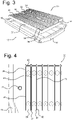
- FIG. 3 shows a battery frame structure 30 carrying four rows 31-34 of battery cells. Each individual cell is placed in a cavity 35, 36 of the battery frame structure 30 and is firmly held in place by a bonding substance that fills up the space between the walls of the cavities 35, 36 and the cell inside the cavity.
- the battery frame structure 30 has longitudinal and transverse peripheral walls 37, 38 and forms a matrix of interconnected battery cells that can be handled as a unit and that can be accurately positioned in the tray 13.
- the height of the peripheral walls 37, 38 and of the cavity walls substantially corresponds to the height of the battery cells 31-34, so that the top and bottom surfaces of the assembly of battery frame structure 30 and cells 31-34 is substantially planar.
- Figure 4 shows an enlarged detail of the battery frame structure 30 near the front transverse beam 16.
- the cells 39, 40 are enclosed within the walls 38,37,43, 44 and 37,43,44,45 of respective cavities of the battery frame structure.
- the gaps 41 and 42 between the cells 39, 40 and the cavity walls are filled with a bonding material, that may be formed by an adhesive material or an expanding compound that can flow and fill the gaps and that can expand and solidify to firmly bond the cells to the cavity walls.
- the expanding compound could provide a pre-compression on the individual battery cells.
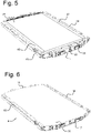
- Figure 5 shows an adhesive layer 49 that is placed on top of the battery cells in the battery frame structure 30.
- the space between the longitudinal side members 14, 15 and the longitudinal peripheral walls 37 of the battery frame structure 30 is filled with a foam block or honeycomb structure 47,48.
- the battery pack 9 is completed by placing a metal top cover 50 over the battery frame structure 30 and attaching the top cover to the adhesive layer 49 and to the side members 14,15 to form a strong casing around the battery cells.
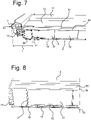
- Figure 7 shows the battery pack 9 connected to the sill profiles 6,7 and to the cross beams 11,12.
- the transverse forces Fs are distributed along the longitudinal side member 15 to the shear planes that are defined by the lower plate 18 and upper plate of the top cover 50.
- a deformation zone with a transverse width D is formed by the sill profile 7, the side member 15 and the foam block or honeycomb material 48. The deformation zone protects the battery cells 31-34 upon side impact and prevents rupture of the cells and intrusion upon impact.
- Figure 8 shows an enlarged detail of a longitudinal venting channel 52 extending in a length direction over the cooling channels 19 in the bottom plate 18.
- gases are evacuated through the venting channel 52 to the rear transverse beam 17, where the gases can escape to environment. Because the venting channel 52 is cooled by the cooling channels 19 in the cooling plate 18, the risk of burn-through is significantly reduced.
- a replaceable insulation layer 53 can be provided over the cooling plate 18 to form the outer layer of the vehicle.
- the thermal isolation provided by the layer 53 mitigates the wind chill factor of the battery pack 9 by the environment and prevents uncontrolled heat transfer.
- the insulation layer 53 gets damaged, for instance in case of a de-road accident, it can be easily removed, inspected and serviced or replaced.
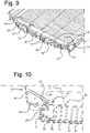
- Figure 9 shows a reinforcement metal end plate 55 that is attached to the transverse wall 38 of the battery frame structure and to the front transverse beam 16, via anchor brackets 56, 57.
- the reinforcement end plate 55 can counteract swelling of the battery cells upon ageing which may cause forces on the sidewalls of the transverse peripheral walls 38 of the battery frame structure 30 of 10-30 kN.
- Figure 10 shows a front frame part 65 of the vehicle that is attached via bolts 60,61 to the anchor bracket 56, and via a bolt 62 to the bracket 24 on the front transverse beam 16.
- the frontal impact force F f is deflected downward to the anchor bracket 56.
- the anchor bracket 56 is arc welded to the end plate 55, and has a number of bonded shear planes that distribute the load across the surface of the anchor bracket across the end plate 55 thereby keeping intrusions of the battery cells in the battery frame structure within safe limits.
Landscapes
- Chemical & Material Sciences (AREA)
- Chemical Kinetics & Catalysis (AREA)
- Electrochemistry (AREA)
- General Chemical & Material Sciences (AREA)
- Engineering & Computer Science (AREA)
- Manufacturing & Machinery (AREA)
- Aviation & Aerospace Engineering (AREA)
- Mechanical Engineering (AREA)
- Transportation (AREA)
- Sustainable Development (AREA)
- Sustainable Energy (AREA)
- Power Engineering (AREA)
- Life Sciences & Earth Sciences (AREA)
- Combustion & Propulsion (AREA)
- Battery Mounting, Suspending (AREA)
- Arrangement Or Mounting Of Propulsion Units For Vehicles (AREA)
Abstract
Description
- The present disclosure relates to an electric vehicle comprising a battery assembly with at least two rows of battery cells attached to a battery frame structure.
- The present disclosure also relates to a battery pack for use in such an electric vehicle and to a method of manufacturing such a battery assembly.
- Electrical vehicles (also known as Battery Electric Vehicle, BEV in short) uses a battery pack to provide electricity to the drive train/motor(s). To provide enough range with current cell technology, in line with customer expectations coming from a fossil fuel car, a BEV battery is located underneath the passenger compartment, basically under the floor. The overall design complexity involves maximizing cell volume (range) into a given footprint (area/volume) provided by the car setup, to the lowest weight possible (range/environmental impact) while also maximizing highly important attributes such as crash safety and vehicle stiffness (NVH and driver experience).
- Up until recently a battery electric vehicle pack has been as a standalone unit with main function of being a safety cage for cells and modules preventing intrusion causing catastrophic failure, while also protecting the sensitive electronics inside from the outside environment. This thinking has led to double structures; Battery and body of the vehicle. Having double structures with the necessary gaps to allow for tolerances and general occupies a volume that could have otherwise been used for integrating more cell volume, further increasing range, had the two systems been seen and engineered as one system. Current art is compensating for this lower volumetric efficiency by using a larger footprint, leading to a shorter stopping distance (in longitudinal and lateral direction) between frame structure and cell footprint. An increasing size of the vehicle results in in increased energy content.
- It is known to provide structural batteries in which the battery casing forms the bottom of the vehicle body and the traditional front floor is removed. The arrays of battery cells are kept in place inside the casing of the battery pack by means of a resin.
- It is an object of the present disclosure to provide an electric vehicle with a battery pack having an improved volumetric efficiency and forming a structural part of the vehicle body. It is another object of the present disclosure to provide a relatively compact structural battery pack for which the number of components are reduced and that can be manufactured in an efficiently manner. It is another object of the present disclosure to provide a battery pack that is provided with an impact absorption zone by which the battery cells are protected from forces arising upon impact.
- An electric vehicle according to the present disclosure comprises a battery frame structure with a number of accommodating cavities, arranged in a matrix, each battery cell being placed in a respective accommodating cavity and connected to adjacent walls of the respective accommodating cavity via a flowable bonding substance being inserted between the cells and the walls of the respective cavity.
- The battery cells are accurately and firmly positioned in the matrix structure of the preformed accommodating cavities. Because the cells are interconnected by being firmly bonded to the walls of the cavities, the number of internal fastener members that are required to keep the cells in place, such as end plates, bolt fixations, tension straps etc., can be reduced. This allows the entire cell foot print to shrink in XY plane, compared to a modular design equivalent.
- The interconnected cells in the matrix of the accommodating cavities form, after curing of the bonding substance, a rigid and integral brick of cells that can be easily handled and that can be accurately placed in the required position relative to a frame or tray of the battery pack and relative to frame parts of the electric vehicle.
- The battery frame structure may comprise longitudinal and transverse side walls. The sidewalls and the walls of the accommodating cavities can be formed by injection molding, casting or additive manufacturing.
- The battery frame structure is first formed from the flowable first material that is cured to harden into a solid and rigid matrix. Next, the individual battery cells are inserted into respective cavities and the space between the battery cells and the matrix of cavities is filled with the bonding substance. After curing of the bonding substance, the cells are tightly held in place and a strong and stiff interconnected battery structure is formed, which allows to down-gauge on other frame parts of the car body such as sub frames, brakes or suspension. Once the cells are bonded, a unitary composite block is formed with large torsional stiffness and structural strength of the matrix of embedded cells. If for instance a weight of the bonded cells is around 450 kg, 200 kg of weight saving of peripheral structure parts could be achieved such that an overall weight increase of 250 kg ensues, in which the bonded cells can be considered as "negative mass".
- In an embodiment, the accommodating cavities are of substantially the same height as a height of the battery cells, a bottom surface of the battery frame structure being substantially flat and supporting a thermally conductive layer contacting the bottom of each battery cell, a top surface of the battery frame structure being placed in a contacting relationship with a top cover. The bottom layer may be formed of a thermal interface material (TIM) for heat transfer from the cells to a bottom cooling plate. The top cover may be formed of an adhesive material and may connect to a top plate forming a shear plane for distribution of lateral forces to the matrix of embedded battery cells.
- The battery frame structure may be placed in a tray member comprising two longitudinal side profiles that are interconnected via a front and rear transverse beam, longitudinal side walls of the battery frame structure extending at a distance from the longitudinal side members, a compressible filler member being placed between the longitudinal side walls of the battery frame structure and the adjacent longitudinal side profile.
- The battery frame structure provides a rigid battery pack with small lateral dimensions. By leaving the space between the side of the cell battery frame structure and the sill members free and not increasing the width of the battery pack, a weight saving is achieved as other parts of the vehicle (suspension, brakes, chassis, wheels) can be made of lighter weight. Also, the deformable material between the cells and the sill members isolates the cells from impact and provide increased safety against intrusion and catastrophic thermal runaway upon side impact.
- A top plate and a bottom plate can be placed in contact with a top and a bottom plane of the battery frame structure, forming a casing, the top and bottom plates being attached to the longitudinal profiles, forming a battery pack. The battery pack can be bolted and/or bonded to the vehicle frame members in an easy to handle manner.
- In an embodiment, the bottom plate comprises a number of cooling channels extending in a length direction, the cooling channels being connected to a cooling fluid inlet at a first transverse beam and being connected to a cooling fluid outlet manifold at a second transverse beam.
- The bottom plate can be covered by an insulating layer that forms the external bottom layer of the vehicle.
- The front and the rear transverse walls of the battery frame structure may be contacting a respective parallel metal end plate that is rigidly connected to the transverse beams. The end plates restrain the forces in the longitudinal direction, caused by swelling of the battery cells upon ageing, which forces may in an example amount to 10-30 kN.
- The front end plate in one embodiment comprises a centrally placed force absorption member, preferably formed by extrusion, having an number of compartments. The absorption member provides a very stiff anchoring point with minimal material use and transfers the forces upon frontal impact into the bonded cell and sandwich structure, where it is distributed into the bonded shear planes spreading the load and keeping cell intrusions within safe limits.
- A method of manufacturing a battery assembly for an electric vehicle, comprising:
- forming a battery frame structure having longitudinal and transverse sidewalls and comprising a number of accommodating cavities by injection molding, casting or additive manufacturing,
- inserting battery cells into the accommodating cavities, the height of the cavities substantially corresponding to the height of the battery members, and
- filling up a space between the battery cells and the walls of the respective cavity with a bonding material and connecting each battery cell to the walls of the respective cell via the bonding material, forming a unitary cell block.
- The method may comprise:
- placing the unitary cell block formed of the interconnected battery cells in a tray member comprising two longitudinal side profiles that are interconnected via a front and rear transverse beam, the longitudinal side walls of the battery frame structure extending at a distance from the longitudinal side profiles,
- inserting a deformable member between the longitudinal side walls of the battery frame structure and the adjacent longitudinal side profile,
- placing a top plate and a bottom plate on the upper and lower surfaces of the battery frame structure, forming a casing, and
- attaching the casing to a vehicle frame part.
- Embodiments of a battery assembly according to the disclosure will, by way of nonlimiting example, be explained in detail with reference to the accompanying drawings. In the drawings:
-
Fig. 1 shows a frame of an electric vehicle comprising a structural battery, -
Fig. 2 shows a tray of a battery assembly according to the present disclosure, -
Fig. 4 shows a battery frame structure according to the disclosure, -
Fig. 5 shows a top view of an enlarged detail of the battery frame structure offig. 4 , -
Fig. 6 shows a battery assembly prior to placing the top cover, -
Fig. 7 shows a battery pack according to the disclosure, -
Fig. 8 shows a transverse cross-sectional view of the battery pack according to the present disclosure, in a forward viewing direction, -
Fig. 9 shows an end plate for reinforcement of the battery frame structure, and -
Fig. 10 shows a front part of the front frame section connected to the battery pack according to the disclosure via an anchor bracket. -
Figure 1 shows a frame 1 of an electric vehicle comprising a body-in-whitefront frame structure 2, a body-in-whiterear floor structure 3, including set or rockers and astructural battery assembly 4 forming a bottom structure 5 of the vehicle. Thestructural battery assembly 4 compriseslongitudinal sill profiles rear frame structures battery pack 9 of interconnected battery cells. Cross beams 11, 12 are connected, for instance via spot welding, to atop plate 10 of thebattery pack 9 and extend in a transverse direction, interconnecting the sill profiles 6,7 and supporting front passenger seats. -
Figure 2 shows atray 13 of thebattery pack 9, havinglongitudinal side member transverse beam 16 and rear andtransverse beam 17. Ametal bottom plate 18 withlongitudinal cooling channels tray 13. A coolinginlet manifold 21 distributes cooling fluid to thechannels outlet manifold 22 at the rear removes the heated coolant from the channels and transports it to a heat exchanger. At the fronttransverse beam 16, connectingbrackets tray 13 to thefront frame structure 2. -
Figure 3 shows abattery frame structure 30 carrying four rows 31-34 of battery cells. Each individual cell is placed in acavity battery frame structure 30 and is firmly held in place by a bonding substance that fills up the space between the walls of thecavities battery frame structure 30 has longitudinal and transverseperipheral walls tray 13. The height of theperipheral walls battery frame structure 30 and cells 31-34 is substantially planar. -
Figure 4 shows an enlarged detail of thebattery frame structure 30 near the fronttransverse beam 16. Thecells walls gaps cells -
Figure 5 shows anadhesive layer 49 that is placed on top of the battery cells in thebattery frame structure 30. The space between thelongitudinal side members peripheral walls 37 of thebattery frame structure 30 is filled with a foam block orhoneycomb structure - As shown in
figure 6 , thebattery pack 9 is completed by placing a metal top cover 50 over thebattery frame structure 30 and attaching the top cover to theadhesive layer 49 and to theside members -
Figure 7 shows thebattery pack 9 connected to the sill profiles 6,7 and to the cross beams 11,12. Upon side impact at thesill profile 7, the transverse forces Fs are distributed along thelongitudinal side member 15 to the shear planes that are defined by thelower plate 18 and upper plate of thetop cover 50. A deformation zone with a transverse width D is formed by thesill profile 7, theside member 15 and the foam block orhoneycomb material 48. The deformation zone protects the battery cells 31-34 upon side impact and prevents rupture of the cells and intrusion upon impact. -
Figure 8 shows an enlarged detail of alongitudinal venting channel 52 extending in a length direction over the coolingchannels 19 in thebottom plate 18. In case of a thermal event, gases are evacuated through the ventingchannel 52 to the reartransverse beam 17, where the gases can escape to environment. Because the ventingchannel 52 is cooled by the coolingchannels 19 in thecooling plate 18, the risk of burn-through is significantly reduced. - A
replaceable insulation layer 53 can be provided over the coolingplate 18 to form the outer layer of the vehicle. The thermal isolation provided by thelayer 53 mitigates the wind chill factor of thebattery pack 9 by the environment and prevents uncontrolled heat transfer. In case theinsulation layer 53 gets damaged, for instance in case of a de-road accident, it can be easily removed, inspected and serviced or replaced. -
Figure 9 shows a reinforcementmetal end plate 55 that is attached to thetransverse wall 38 of the battery frame structure and to the fronttransverse beam 16, viaanchor brackets reinforcement end plate 55 can counteract swelling of the battery cells upon ageing which may cause forces on the sidewalls of the transverseperipheral walls 38 of thebattery frame structure 30 of 10-30 kN. -
Figure 10 shows afront frame part 65 of the vehicle that is attached viabolts 60,61 to theanchor bracket 56, and via abolt 62 to thebracket 24 on the fronttransverse beam 16. The frontal impact force Ff is deflected downward to theanchor bracket 56. Theanchor bracket 56 is arc welded to theend plate 55, and has a number of bonded shear planes that distribute the load across the surface of the anchor bracket across theend plate 55 thereby keeping intrusions of the battery cells in the battery frame structure within safe limits.
Claims (14)
- Electric vehicle comprising a battery assembly (4) with at least two rows (31-34) of battery cells (39,40) attached to a battery frame structure (30), wherein the battery frame structure comprises a number of accommodating cavities (35,36), arranged in a matrix, each battery cell (39,40) being placed in a respective accommodating cavity (35,36) and connected to adjacent walls (43,44,45) of the respective accommodating cavity (35,36) via a flowable bonding substance being inserted in a gap (41,42) between the cells and the walls (43,44,45) of the respective cavity.
- Electric vehicle according to claim 1, wherein the battery frame structure (30) comprises longitudinal and transverse peripheral walls (37,38), the peripheral walls and the walls of the accommodating cavities (43-45) being formed by injection molding, casting or additive manufacturing, of a first, solidifying material, the flowable bonding substance comprising a second substance.
- Electric vehicle according to claim 1 or 2, wherein the accommodating cavities (35,36) are of substantially the same height as a height of the battery cells (39,40), a bottom surface of the battery frame structure (30) being substantially flat and supporting a thermally conductive layer (18) contacting the bottom of each battery cell (39,40), a top surface of the battery frame structure (30) being placed in a contacting relationship with a top cover (49,50).
- Electric vehicle according to any of the preceding claims, wherein the battery frame structure (30) is placed in a tray member (13) comprising two longitudinal side profiles (14,15) that are interconnected via a front and rear transverse beam (16,17), longitudinal peripheral walls (37) of the battery frame structure (30) extending at a distance from the longitudinal side profiles (15,16), a compressible filler member (47,48) being placed between the longitudinal peripheral walls (37) of the battery frame structure (30) and the respective adjacent longitudinal side profile (14,15).
- Electric vehicle according to claim 4, a top plate (50) and a bottom plate (18) being placed in contact with the top and bottom plane of the battery frame structure (30), the top and bottom plates (50,18) being attached to the longitudinal side profiles (14,15) forming a casing.
- Electric vehicle according to claim 4 or 5, the bottom plate (18) comprising a number of cooling channels (19,20) extending in a length direction, the cooling channels being connected to a cooling fluid inlet (21) at a first transverse beam (16) and being connected to a cooling fluid outlet manifold (22) at a second transverse beam (17).
- Electric vehicle according to claim 6, the bottom plate (18) being covered by an insulating layer (53) forming the outer bottom layer of the vehicle.
- Electric vehicle according to claim 5, 6 or 7, the front and the rear peripheral walls ( 38) of the battery frame structure (30) contacting a respective parallel metal reinforcement plate (55) contacting the front and rear peripheral walls (38) and connected along its width to the front and rear transverse beams (16,17).
- Electric vehicle according to claim 8, the front reinforcement plate (50) comprising a centrally placed reinforcement member (56), preferably formed by extrusion, having a number of compartments.
- Battery pack (9) for use in an electric vehicle, at least two rows (31-34) of battery cells (39,40) attached to a battery frame structure (30) with a number of accommodating cavities (35,36), arranged in a matrix, each battery cell (39,40) being placed in a respective accommodating cavity (35,36) and connected to adjacent walls (43,44,45) of the respective accommodating cavity (35,36) via a flowable bonding substance being inserted in a gap (41,42) between the cells (39,40) and the walls (43-45) of the respective cavity (35,36), the battery frame structure (30) being placed in a tray member (13) comprising two longitudinal side profiles (14,15) that are interconnected via a front and rear transverse beam (16,17), longitudinal peripheral walls (37) of the battery frame structure (30) extending at a distance from the longitudinal side profiles (14,15), a compressible filler member (47,48) being placed between the longitudinal peripheral walls (37) of the battery frame structure (30) and the adjacent longitudinal side profile (14,15).
- Method of manufacturing a battery assembly (9) for an electric vehicle, comprising:- forming a battery frame structure (30) having longitudinal and transverse peripheral walls (37,38) and comprising a number of accommodating cavities (35,36) arranged in a matrix by injection molding, casting or additive manufacturing,- inserting battery cells (39,40) into the accommodating cavities, and- filling up a gap (41,42) between the cells and the walls (43,44,45) of the respective cavity with a bonding material, connecting each battery cell (39,40) to the walls (43,44,45) of the respective cavity via the bonding material forming a unitary cell block.
- Method according to claim 11, comprising- placing the unitary cell block formed by the battery frame structure (30) and the connected battery cells (39,40) in a tray member (13) comprising two longitudinal side profiles (14,15) that are interconnected via a front and rear transverse beam (16,17), the longitudinal peripheral walls (37) of the battery frame structure (30) extending at a distance from the longitudinal side profiles (14,15),- inserting a deformable member (47,48) between the longitudinal peripheral walls (37) of the battery frame structure (30) and the adjacent longitudinal side profile (14,15),- placing a top plate (50) and a bottom plate (18) on the top and bottom surfaces of the battery frame structure (30).
- Method according to claim 12 comprising attaching the top and bottom plates (18,50) to a vehicle frame.
- Method according to claim 12 or 13, comprising connecting the top and bottom plates (18,50) to longitudinal side profiles (14,15), forming a casing.
Priority Applications (3)
| Application Number | Priority Date | Filing Date | Title |
|---|---|---|---|
| EP21186240.4A EP4120435A1 (en) | 2021-07-16 | 2021-07-16 | Structural battery for an electric vehicle comprising a battery cell support matrix |
| US17/861,319 US20230022211A1 (en) | 2021-07-16 | 2022-07-11 | Structural Battery for an Electric Vehicle Comprising a Battery Cell Support Matrix |
| CN202210842792.1A CN115621603A (en) | 2021-07-16 | 2022-07-18 | Structural battery for electric vehicle comprising a battery cell support matrix for the battery |
Applications Claiming Priority (1)
| Application Number | Priority Date | Filing Date | Title |
|---|---|---|---|
| EP21186240.4A EP4120435A1 (en) | 2021-07-16 | 2021-07-16 | Structural battery for an electric vehicle comprising a battery cell support matrix |
Publications (1)
| Publication Number | Publication Date |
|---|---|
| EP4120435A1 true EP4120435A1 (en) | 2023-01-18 |
Family
ID=76958881
Family Applications (1)
| Application Number | Title | Priority Date | Filing Date |
|---|---|---|---|
| EP21186240.4A Pending EP4120435A1 (en) | 2021-07-16 | 2021-07-16 | Structural battery for an electric vehicle comprising a battery cell support matrix |
Country Status (3)
| Country | Link |
|---|---|
| US (1) | US20230022211A1 (en) |
| EP (1) | EP4120435A1 (en) |
| CN (1) | CN115621603A (en) |
Families Citing this family (2)
| Publication number | Priority date | Publication date | Assignee | Title |
|---|---|---|---|---|
| UA120429C2 (en) * | 2014-03-19 | 2019-12-10 | Філіп Морріс Продактс С.А. | Monolithic plane with electrical contacts and methods for manufacturing the same |
| CN116487809B (en) * | 2023-06-25 | 2023-09-15 | 北京玖行智研交通科技有限公司 | Power battery assembly, power battery box assembly and electric vehicle |
Citations (6)
| Publication number | Priority date | Publication date | Assignee | Title |
|---|---|---|---|---|
| EP3584877A1 (en) * | 2018-05-16 | 2019-12-25 | Samsung SDI Co., Ltd. | Battery pack comprising a frame profile with integral coolant circuit elements |
| EP3739683A1 (en) * | 2018-06-20 | 2020-11-18 | Lg Chem, Ltd. | Battery module, battery pack comprising same battery module, and vehicle comprising same battery pack |
| US20210013463A1 (en) * | 2018-03-27 | 2021-01-14 | Panasonic Intellectual Property Management Co., Ltd. | Power storage module |
| US20210135313A1 (en) * | 2017-03-16 | 2021-05-06 | Audi Ag | Battery for a motor vehicle and motor vehicle |
| DE102019220260A1 (en) * | 2019-12-19 | 2021-06-24 | Volkswagen Aktiengesellschaft | High-voltage battery for a vehicle |
| US20210203028A1 (en) * | 2019-12-31 | 2021-07-01 | Samsung Sdi Co., Ltd. | Battery pack |
-
2021
- 2021-07-16 EP EP21186240.4A patent/EP4120435A1/en active Pending
-
2022
- 2022-07-11 US US17/861,319 patent/US20230022211A1/en active Pending
- 2022-07-18 CN CN202210842792.1A patent/CN115621603A/en active Pending
Patent Citations (6)
| Publication number | Priority date | Publication date | Assignee | Title |
|---|---|---|---|---|
| US20210135313A1 (en) * | 2017-03-16 | 2021-05-06 | Audi Ag | Battery for a motor vehicle and motor vehicle |
| US20210013463A1 (en) * | 2018-03-27 | 2021-01-14 | Panasonic Intellectual Property Management Co., Ltd. | Power storage module |
| EP3584877A1 (en) * | 2018-05-16 | 2019-12-25 | Samsung SDI Co., Ltd. | Battery pack comprising a frame profile with integral coolant circuit elements |
| EP3739683A1 (en) * | 2018-06-20 | 2020-11-18 | Lg Chem, Ltd. | Battery module, battery pack comprising same battery module, and vehicle comprising same battery pack |
| DE102019220260A1 (en) * | 2019-12-19 | 2021-06-24 | Volkswagen Aktiengesellschaft | High-voltage battery for a vehicle |
| US20210203028A1 (en) * | 2019-12-31 | 2021-07-01 | Samsung Sdi Co., Ltd. | Battery pack |
Also Published As
| Publication number | Publication date |
|---|---|
| CN115621603A (en) | 2023-01-17 |
| US20230022211A1 (en) | 2023-01-26 |
Similar Documents
| Publication | Publication Date | Title |
|---|---|---|
| US20230022211A1 (en) | Structural Battery for an Electric Vehicle Comprising a Battery Cell Support Matrix | |
| JP7405299B2 (en) | Battery mounting structure | |
| US11376941B2 (en) | Electric vehicle battery cooling structure | |
| KR101977442B1 (en) | Battery device and method | |
| JP5372128B2 (en) | Side impact energy absorption and dispersion system using battery pack | |
| JP7339565B2 (en) | automobile undercarriage | |
| US20240258599A1 (en) | Drive Battery for a Motor Vehicle, and Motor Vehicle Comprising Such a Drive Battery | |
| US20230025278A1 (en) | Structural Battery With Reduced Sill Height | |
| AU2023247710A1 (en) | Vehicle | |
| US20240234851A1 (en) | Battery packs with safety features and methods of installing such packs on truck frames | |
| US20220294060A1 (en) | Battery Box with Frame Reinforcing Element | |
| CN114940056B (en) | Vehicle with a vehicle body having a vehicle body support | |
| CN217944883U (en) | Battery package, automobile body structure and vehicle | |
| CN117546350A (en) | Drive battery for a motor vehicle and motor vehicle having such a drive battery | |
| CN114590115A (en) | Vehicle with a steering wheel | |
| EP4231399A1 (en) | Structural battery pack cell signal and conversion pass-through | |
| US20230026490A1 (en) | Structural Battery for an Electric Vehicle | |
| US20230108456A1 (en) | Structural Battery for an Electric Vehicle and Method of Manufacturing | |
| CN115140171B (en) | Vehicle body structure and vehicle | |
| US20240079686A1 (en) | Battery modules with casted module enclosures and methods of fabricating thereof | |
| CN117219941A (en) | Battery module, battery and vehicle | |
| CN118539068A (en) | Power battery, assembling method thereof and vehicle | |
| GB2623971A (en) | Structural member | |
| WO2023175354A1 (en) | Monocoque vehicle, structured battery and method of manufacture | |
| GB2617437A (en) | A structured battery and method of manufacture |
Legal Events
| Date | Code | Title | Description |
|---|---|---|---|
| PUAI | Public reference made under article 153(3) epc to a published international application that has entered the european phase |
Free format text: ORIGINAL CODE: 0009012 |
|
| STAA | Information on the status of an ep patent application or granted ep patent |
Free format text: STATUS: THE APPLICATION HAS BEEN PUBLISHED |
|
| AK | Designated contracting states |
Kind code of ref document: A1 Designated state(s): AL AT BE BG CH CY CZ DE DK EE ES FI FR GB GR HR HU IE IS IT LI LT LU LV MC MK MT NL NO PL PT RO RS SE SI SK SM TR |
|
| STAA | Information on the status of an ep patent application or granted ep patent |
Free format text: STATUS: REQUEST FOR EXAMINATION WAS MADE |
|
| 17P | Request for examination filed |
Effective date: 20230314 |
|
| RBV | Designated contracting states (corrected) |
Designated state(s): AL AT BE BG CH CY CZ DE DK EE ES FI FR GB GR HR HU IE IS IT LI LT LU LV MC MK MT NL NO PL PT RO RS SE SI SK SM TR |