EP4120435A1 - Batterie structurelle pour un véhicule électrique comprenant une matrice de support de cellule de batterie - Google Patents
Batterie structurelle pour un véhicule électrique comprenant une matrice de support de cellule de batterie Download PDFInfo
- Publication number
- EP4120435A1 EP4120435A1 EP21186240.4A EP21186240A EP4120435A1 EP 4120435 A1 EP4120435 A1 EP 4120435A1 EP 21186240 A EP21186240 A EP 21186240A EP 4120435 A1 EP4120435 A1 EP 4120435A1
- Authority
- EP
- European Patent Office
- Prior art keywords
- battery
- frame structure
- battery frame
- electric vehicle
- walls
- Prior art date
- Legal status (The legal status is an assumption and is not a legal conclusion. Google has not performed a legal analysis and makes no representation as to the accuracy of the status listed.)
- Pending
Links
Images

Classifications
-
- H—ELECTRICITY
- H01—ELECTRIC ELEMENTS
- H01M—PROCESSES OR MEANS, e.g. BATTERIES, FOR THE DIRECT CONVERSION OF CHEMICAL ENERGY INTO ELECTRICAL ENERGY
- H01M50/00—Constructional details or processes of manufacture of the non-active parts of electrochemical cells other than fuel cells, e.g. hybrid cells
- H01M50/20—Mountings; Secondary casings or frames; Racks, modules or packs; Suspension devices; Shock absorbers; Transport or carrying devices; Holders
- H01M50/249—Mountings; Secondary casings or frames; Racks, modules or packs; Suspension devices; Shock absorbers; Transport or carrying devices; Holders specially adapted for aircraft or vehicles, e.g. cars or trains
-
- B—PERFORMING OPERATIONS; TRANSPORTING
- B60—VEHICLES IN GENERAL
- B60K—ARRANGEMENT OR MOUNTING OF PROPULSION UNITS OR OF TRANSMISSIONS IN VEHICLES; ARRANGEMENT OR MOUNTING OF PLURAL DIVERSE PRIME-MOVERS IN VEHICLES; AUXILIARY DRIVES FOR VEHICLES; INSTRUMENTATION OR DASHBOARDS FOR VEHICLES; ARRANGEMENTS IN CONNECTION WITH COOLING, AIR INTAKE, GAS EXHAUST OR FUEL SUPPLY OF PROPULSION UNITS IN VEHICLES
- B60K1/00—Arrangement or mounting of electrical propulsion units
- B60K1/04—Arrangement or mounting of electrical propulsion units of the electric storage means for propulsion
-
- B—PERFORMING OPERATIONS; TRANSPORTING
- B60—VEHICLES IN GENERAL
- B60L—PROPULSION OF ELECTRICALLY-PROPELLED VEHICLES; SUPPLYING ELECTRIC POWER FOR AUXILIARY EQUIPMENT OF ELECTRICALLY-PROPELLED VEHICLES; ELECTRODYNAMIC BRAKE SYSTEMS FOR VEHICLES IN GENERAL; MAGNETIC SUSPENSION OR LEVITATION FOR VEHICLES; MONITORING OPERATING VARIABLES OF ELECTRICALLY-PROPELLED VEHICLES; ELECTRIC SAFETY DEVICES FOR ELECTRICALLY-PROPELLED VEHICLES
- B60L50/00—Electric propulsion with power supplied within the vehicle
- B60L50/50—Electric propulsion with power supplied within the vehicle using propulsion power supplied by batteries or fuel cells
- B60L50/60—Electric propulsion with power supplied within the vehicle using propulsion power supplied by batteries or fuel cells using power supplied by batteries
- B60L50/64—Constructional details of batteries specially adapted for electric vehicles
-
- H—ELECTRICITY
- H01—ELECTRIC ELEMENTS
- H01M—PROCESSES OR MEANS, e.g. BATTERIES, FOR THE DIRECT CONVERSION OF CHEMICAL ENERGY INTO ELECTRICAL ENERGY
- H01M10/00—Secondary cells; Manufacture thereof
- H01M10/60—Heating or cooling; Temperature control
- H01M10/61—Types of temperature control
- H01M10/613—Cooling or keeping cold
-
- H—ELECTRICITY
- H01—ELECTRIC ELEMENTS
- H01M—PROCESSES OR MEANS, e.g. BATTERIES, FOR THE DIRECT CONVERSION OF CHEMICAL ENERGY INTO ELECTRICAL ENERGY
- H01M10/00—Secondary cells; Manufacture thereof
- H01M10/60—Heating or cooling; Temperature control
- H01M10/62—Heating or cooling; Temperature control specially adapted for specific applications
- H01M10/625—Vehicles
-
- H—ELECTRICITY
- H01—ELECTRIC ELEMENTS
- H01M—PROCESSES OR MEANS, e.g. BATTERIES, FOR THE DIRECT CONVERSION OF CHEMICAL ENERGY INTO ELECTRICAL ENERGY
- H01M10/00—Secondary cells; Manufacture thereof
- H01M10/60—Heating or cooling; Temperature control
- H01M10/64—Heating or cooling; Temperature control characterised by the shape of the cells
- H01M10/647—Prismatic or flat cells, e.g. pouch cells
-
- H—ELECTRICITY
- H01—ELECTRIC ELEMENTS
- H01M—PROCESSES OR MEANS, e.g. BATTERIES, FOR THE DIRECT CONVERSION OF CHEMICAL ENERGY INTO ELECTRICAL ENERGY
- H01M10/00—Secondary cells; Manufacture thereof
- H01M10/60—Heating or cooling; Temperature control
- H01M10/65—Means for temperature control structurally associated with the cells
- H01M10/653—Means for temperature control structurally associated with the cells characterised by electrically insulating or thermally conductive materials
-
- H—ELECTRICITY
- H01—ELECTRIC ELEMENTS
- H01M—PROCESSES OR MEANS, e.g. BATTERIES, FOR THE DIRECT CONVERSION OF CHEMICAL ENERGY INTO ELECTRICAL ENERGY
- H01M10/00—Secondary cells; Manufacture thereof
- H01M10/60—Heating or cooling; Temperature control
- H01M10/65—Means for temperature control structurally associated with the cells
- H01M10/655—Solid structures for heat exchange or heat conduction
- H01M10/6554—Rods or plates
-
- H—ELECTRICITY
- H01—ELECTRIC ELEMENTS
- H01M—PROCESSES OR MEANS, e.g. BATTERIES, FOR THE DIRECT CONVERSION OF CHEMICAL ENERGY INTO ELECTRICAL ENERGY
- H01M10/00—Secondary cells; Manufacture thereof
- H01M10/60—Heating or cooling; Temperature control
- H01M10/65—Means for temperature control structurally associated with the cells
- H01M10/655—Solid structures for heat exchange or heat conduction
- H01M10/6556—Solid parts with flow channel passages or pipes for heat exchange
-
- H—ELECTRICITY
- H01—ELECTRIC ELEMENTS
- H01M—PROCESSES OR MEANS, e.g. BATTERIES, FOR THE DIRECT CONVERSION OF CHEMICAL ENERGY INTO ELECTRICAL ENERGY
- H01M10/00—Secondary cells; Manufacture thereof
- H01M10/60—Heating or cooling; Temperature control
- H01M10/65—Means for temperature control structurally associated with the cells
- H01M10/656—Means for temperature control structurally associated with the cells characterised by the type of heat-exchange fluid
- H01M10/6567—Liquids
- H01M10/6568—Liquids characterised by flow circuits, e.g. loops, located externally to the cells or cell casings
-
- H—ELECTRICITY
- H01—ELECTRIC ELEMENTS
- H01M—PROCESSES OR MEANS, e.g. BATTERIES, FOR THE DIRECT CONVERSION OF CHEMICAL ENERGY INTO ELECTRICAL ENERGY
- H01M10/00—Secondary cells; Manufacture thereof
- H01M10/60—Heating or cooling; Temperature control
- H01M10/65—Means for temperature control structurally associated with the cells
- H01M10/658—Means for temperature control structurally associated with the cells by thermal insulation or shielding
-
- H—ELECTRICITY
- H01—ELECTRIC ELEMENTS
- H01M—PROCESSES OR MEANS, e.g. BATTERIES, FOR THE DIRECT CONVERSION OF CHEMICAL ENERGY INTO ELECTRICAL ENERGY
- H01M50/00—Constructional details or processes of manufacture of the non-active parts of electrochemical cells other than fuel cells, e.g. hybrid cells
- H01M50/20—Mountings; Secondary casings or frames; Racks, modules or packs; Suspension devices; Shock absorbers; Transport or carrying devices; Holders
- H01M50/204—Racks, modules or packs for multiple batteries or multiple cells
- H01M50/207—Racks, modules or packs for multiple batteries or multiple cells characterised by their shape
- H01M50/209—Racks, modules or packs for multiple batteries or multiple cells characterised by their shape adapted for prismatic or rectangular cells
-
- H—ELECTRICITY
- H01—ELECTRIC ELEMENTS
- H01M—PROCESSES OR MEANS, e.g. BATTERIES, FOR THE DIRECT CONVERSION OF CHEMICAL ENERGY INTO ELECTRICAL ENERGY
- H01M50/00—Constructional details or processes of manufacture of the non-active parts of electrochemical cells other than fuel cells, e.g. hybrid cells
- H01M50/20—Mountings; Secondary casings or frames; Racks, modules or packs; Suspension devices; Shock absorbers; Transport or carrying devices; Holders
- H01M50/233—Mountings; Secondary casings or frames; Racks, modules or packs; Suspension devices; Shock absorbers; Transport or carrying devices; Holders characterised by physical properties of casings or racks, e.g. dimensions
- H01M50/242—Mountings; Secondary casings or frames; Racks, modules or packs; Suspension devices; Shock absorbers; Transport or carrying devices; Holders characterised by physical properties of casings or racks, e.g. dimensions adapted for protecting batteries against vibrations, collision impact or swelling
-
- H—ELECTRICITY
- H01—ELECTRIC ELEMENTS
- H01M—PROCESSES OR MEANS, e.g. BATTERIES, FOR THE DIRECT CONVERSION OF CHEMICAL ENERGY INTO ELECTRICAL ENERGY
- H01M50/00—Constructional details or processes of manufacture of the non-active parts of electrochemical cells other than fuel cells, e.g. hybrid cells
- H01M50/20—Mountings; Secondary casings or frames; Racks, modules or packs; Suspension devices; Shock absorbers; Transport or carrying devices; Holders
- H01M50/244—Secondary casings; Racks; Suspension devices; Carrying devices; Holders characterised by their mounting method
-
- H—ELECTRICITY
- H01—ELECTRIC ELEMENTS
- H01M—PROCESSES OR MEANS, e.g. BATTERIES, FOR THE DIRECT CONVERSION OF CHEMICAL ENERGY INTO ELECTRICAL ENERGY
- H01M50/00—Constructional details or processes of manufacture of the non-active parts of electrochemical cells other than fuel cells, e.g. hybrid cells
- H01M50/20—Mountings; Secondary casings or frames; Racks, modules or packs; Suspension devices; Shock absorbers; Transport or carrying devices; Holders
- H01M50/262—Mountings; Secondary casings or frames; Racks, modules or packs; Suspension devices; Shock absorbers; Transport or carrying devices; Holders with fastening means, e.g. locks
- H01M50/264—Mountings; Secondary casings or frames; Racks, modules or packs; Suspension devices; Shock absorbers; Transport or carrying devices; Holders with fastening means, e.g. locks for cells or batteries, e.g. straps, tie rods or peripheral frames
-
- H—ELECTRICITY
- H01—ELECTRIC ELEMENTS
- H01M—PROCESSES OR MEANS, e.g. BATTERIES, FOR THE DIRECT CONVERSION OF CHEMICAL ENERGY INTO ELECTRICAL ENERGY
- H01M50/00—Constructional details or processes of manufacture of the non-active parts of electrochemical cells other than fuel cells, e.g. hybrid cells
- H01M50/20—Mountings; Secondary casings or frames; Racks, modules or packs; Suspension devices; Shock absorbers; Transport or carrying devices; Holders
- H01M50/289—Mountings; Secondary casings or frames; Racks, modules or packs; Suspension devices; Shock absorbers; Transport or carrying devices; Holders characterised by spacing elements or positioning means within frames, racks or packs
-
- H—ELECTRICITY
- H01—ELECTRIC ELEMENTS
- H01M—PROCESSES OR MEANS, e.g. BATTERIES, FOR THE DIRECT CONVERSION OF CHEMICAL ENERGY INTO ELECTRICAL ENERGY
- H01M2220/00—Batteries for particular applications
- H01M2220/20—Batteries in motive systems, e.g. vehicle, ship, plane
-
- Y—GENERAL TAGGING OF NEW TECHNOLOGICAL DEVELOPMENTS; GENERAL TAGGING OF CROSS-SECTIONAL TECHNOLOGIES SPANNING OVER SEVERAL SECTIONS OF THE IPC; TECHNICAL SUBJECTS COVERED BY FORMER USPC CROSS-REFERENCE ART COLLECTIONS [XRACs] AND DIGESTS
- Y02—TECHNOLOGIES OR APPLICATIONS FOR MITIGATION OR ADAPTATION AGAINST CLIMATE CHANGE
- Y02E—REDUCTION OF GREENHOUSE GAS [GHG] EMISSIONS, RELATED TO ENERGY GENERATION, TRANSMISSION OR DISTRIBUTION
- Y02E60/00—Enabling technologies; Technologies with a potential or indirect contribution to GHG emissions mitigation
- Y02E60/10—Energy storage using batteries
Definitions
- the present disclosure relates to an electric vehicle comprising a battery assembly with at least two rows of battery cells attached to a battery frame structure.
- the present disclosure also relates to a battery pack for use in such an electric vehicle and to a method of manufacturing such a battery assembly.
- BEV Battery Electric Vehicle
- a BEV battery is located underneath the passenger compartment, basically under the floor.
- the overall design complexity involves maximizing cell volume (range) into a given footprint (area/volume) provided by the car setup, to the lowest weight possible (range/environmental impact) while also maximizing highly important attributes such as crash safety and vehicle stiffness (NVH and driver experience).
- An electric vehicle comprises a battery frame structure with a number of accommodating cavities, arranged in a matrix, each battery cell being placed in a respective accommodating cavity and connected to adjacent walls of the respective accommodating cavity via a flowable bonding substance being inserted between the cells and the walls of the respective cavity.
- the battery cells are accurately and firmly positioned in the matrix structure of the preformed accommodating cavities. Because the cells are interconnected by being firmly bonded to the walls of the cavities, the number of internal fastener members that are required to keep the cells in place, such as end plates, bolt fixations, tension straps etc., can be reduced. This allows the entire cell foot print to shrink in XY plane, compared to a modular design equivalent.
- the interconnected cells in the matrix of the accommodating cavities form, after curing of the bonding substance, a rigid and integral brick of cells that can be easily handled and that can be accurately placed in the required position relative to a frame or tray of the battery pack and relative to frame parts of the electric vehicle.
- the battery frame structure may comprise longitudinal and transverse side walls.
- the sidewalls and the walls of the accommodating cavities can be formed by injection molding, casting or additive manufacturing.
- the battery frame structure is first formed from the flowable first material that is cured to harden into a solid and rigid matrix.
- the individual battery cells are inserted into respective cavities and the space between the battery cells and the matrix of cavities is filled with the bonding substance.
- the cells are tightly held in place and a strong and stiff interconnected battery structure is formed, which allows to down-gauge on other frame parts of the car body such as sub frames, brakes or suspension.
- a unitary composite block is formed with large torsional stiffness and structural strength of the matrix of embedded cells. If for instance a weight of the bonded cells is around 450 kg, 200 kg of weight saving of peripheral structure parts could be achieved such that an overall weight increase of 250 kg ensues, in which the bonded cells can be considered as "negative mass”.
- the accommodating cavities are of substantially the same height as a height of the battery cells, a bottom surface of the battery frame structure being substantially flat and supporting a thermally conductive layer contacting the bottom of each battery cell, a top surface of the battery frame structure being placed in a contacting relationship with a top cover.
- the bottom layer may be formed of a thermal interface material (TIM) for heat transfer from the cells to a bottom cooling plate.
- the top cover may be formed of an adhesive material and may connect to a top plate forming a shear plane for distribution of lateral forces to the matrix of embedded battery cells.
- the battery frame structure may be placed in a tray member comprising two longitudinal side profiles that are interconnected via a front and rear transverse beam, longitudinal side walls of the battery frame structure extending at a distance from the longitudinal side members, a compressible filler member being placed between the longitudinal side walls of the battery frame structure and the adjacent longitudinal side profile.
- the battery frame structure provides a rigid battery pack with small lateral dimensions.
- a weight saving is achieved as other parts of the vehicle (suspension, brakes, chassis, wheels) can be made of lighter weight.
- the deformable material between the cells and the sill members isolates the cells from impact and provide increased safety against intrusion and catastrophic thermal runaway upon side impact.
- a top plate and a bottom plate can be placed in contact with a top and a bottom plane of the battery frame structure, forming a casing, the top and bottom plates being attached to the longitudinal profiles, forming a battery pack.
- the battery pack can be bolted and/or bonded to the vehicle frame members in an easy to handle manner.
- the bottom plate comprises a number of cooling channels extending in a length direction, the cooling channels being connected to a cooling fluid inlet at a first transverse beam and being connected to a cooling fluid outlet manifold at a second transverse beam.
- the bottom plate can be covered by an insulating layer that forms the external bottom layer of the vehicle.
- the front and the rear transverse walls of the battery frame structure may be contacting a respective parallel metal end plate that is rigidly connected to the transverse beams.
- the end plates restrain the forces in the longitudinal direction, caused by swelling of the battery cells upon ageing, which forces may in an example amount to 10-30 kN.
- the front end plate in one embodiment comprises a centrally placed force absorption member, preferably formed by extrusion, having an number of compartments.
- the absorption member provides a very stiff anchoring point with minimal material use and transfers the forces upon frontal impact into the bonded cell and sandwich structure, where it is distributed into the bonded shear planes spreading the load and keeping cell intrusions within safe limits.
- a method of manufacturing a battery assembly for an electric vehicle comprising:
- the method may comprise:
- Figure 1 shows a frame 1 of an electric vehicle comprising a body-in-white front frame structure 2, a body-in-white rear floor structure 3, including set or rockers and a structural battery assembly 4 forming a bottom structure 5 of the vehicle.
- the structural battery assembly 4 comprises longitudinal sill profiles 6,7 that interconnect the front and rear frame structures 2,3 and that support a battery pack 9 of interconnected battery cells.
- Cross beams 11, 12 are connected, for instance via spot welding, to a top plate 10 of the battery pack 9 and extend in a transverse direction, interconnecting the sill profiles 6,7 and supporting front passenger seats.
- Figure 2 shows a tray 13 of the battery pack 9, having longitudinal side member 14,15 that are interconnected by front transverse beam 16 and rear and transverse beam 17.
- a metal bottom plate 18 with longitudinal cooling channels 19, 20 forms the bottom of the tray 13.
- a cooling inlet manifold 21 distributes cooling fluid to the channels 19,20 and an outlet manifold 22 at the rear removes the heated coolant from the channels and transports it to a heat exchanger.
- connecting brackets 24, 25 are provided for providing a rigid connection of the tray 13 to the front frame structure 2.
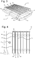
- FIG. 3 shows a battery frame structure 30 carrying four rows 31-34 of battery cells. Each individual cell is placed in a cavity 35, 36 of the battery frame structure 30 and is firmly held in place by a bonding substance that fills up the space between the walls of the cavities 35, 36 and the cell inside the cavity.
- the battery frame structure 30 has longitudinal and transverse peripheral walls 37, 38 and forms a matrix of interconnected battery cells that can be handled as a unit and that can be accurately positioned in the tray 13.
- the height of the peripheral walls 37, 38 and of the cavity walls substantially corresponds to the height of the battery cells 31-34, so that the top and bottom surfaces of the assembly of battery frame structure 30 and cells 31-34 is substantially planar.
- Figure 4 shows an enlarged detail of the battery frame structure 30 near the front transverse beam 16.
- the cells 39, 40 are enclosed within the walls 38,37,43, 44 and 37,43,44,45 of respective cavities of the battery frame structure.
- the gaps 41 and 42 between the cells 39, 40 and the cavity walls are filled with a bonding material, that may be formed by an adhesive material or an expanding compound that can flow and fill the gaps and that can expand and solidify to firmly bond the cells to the cavity walls.
- the expanding compound could provide a pre-compression on the individual battery cells.
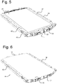
- Figure 5 shows an adhesive layer 49 that is placed on top of the battery cells in the battery frame structure 30.
- the space between the longitudinal side members 14, 15 and the longitudinal peripheral walls 37 of the battery frame structure 30 is filled with a foam block or honeycomb structure 47,48.
- the battery pack 9 is completed by placing a metal top cover 50 over the battery frame structure 30 and attaching the top cover to the adhesive layer 49 and to the side members 14,15 to form a strong casing around the battery cells.
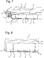
- Figure 7 shows the battery pack 9 connected to the sill profiles 6,7 and to the cross beams 11,12.
- the transverse forces Fs are distributed along the longitudinal side member 15 to the shear planes that are defined by the lower plate 18 and upper plate of the top cover 50.
- a deformation zone with a transverse width D is formed by the sill profile 7, the side member 15 and the foam block or honeycomb material 48. The deformation zone protects the battery cells 31-34 upon side impact and prevents rupture of the cells and intrusion upon impact.
- Figure 8 shows an enlarged detail of a longitudinal venting channel 52 extending in a length direction over the cooling channels 19 in the bottom plate 18.
- gases are evacuated through the venting channel 52 to the rear transverse beam 17, where the gases can escape to environment. Because the venting channel 52 is cooled by the cooling channels 19 in the cooling plate 18, the risk of burn-through is significantly reduced.
- a replaceable insulation layer 53 can be provided over the cooling plate 18 to form the outer layer of the vehicle.
- the thermal isolation provided by the layer 53 mitigates the wind chill factor of the battery pack 9 by the environment and prevents uncontrolled heat transfer.
- the insulation layer 53 gets damaged, for instance in case of a de-road accident, it can be easily removed, inspected and serviced or replaced.
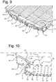
- Figure 9 shows a reinforcement metal end plate 55 that is attached to the transverse wall 38 of the battery frame structure and to the front transverse beam 16, via anchor brackets 56, 57.
- the reinforcement end plate 55 can counteract swelling of the battery cells upon ageing which may cause forces on the sidewalls of the transverse peripheral walls 38 of the battery frame structure 30 of 10-30 kN.
- Figure 10 shows a front frame part 65 of the vehicle that is attached via bolts 60,61 to the anchor bracket 56, and via a bolt 62 to the bracket 24 on the front transverse beam 16.
- the frontal impact force F f is deflected downward to the anchor bracket 56.
- the anchor bracket 56 is arc welded to the end plate 55, and has a number of bonded shear planes that distribute the load across the surface of the anchor bracket across the end plate 55 thereby keeping intrusions of the battery cells in the battery frame structure within safe limits.
Landscapes
- Chemical & Material Sciences (AREA)
- Chemical Kinetics & Catalysis (AREA)
- Electrochemistry (AREA)
- General Chemical & Material Sciences (AREA)
- Engineering & Computer Science (AREA)
- Manufacturing & Machinery (AREA)
- Aviation & Aerospace Engineering (AREA)
- Mechanical Engineering (AREA)
- Transportation (AREA)
- Sustainable Development (AREA)
- Sustainable Energy (AREA)
- Power Engineering (AREA)
- Life Sciences & Earth Sciences (AREA)
- Combustion & Propulsion (AREA)
- Arrangement Or Mounting Of Propulsion Units For Vehicles (AREA)
- Battery Mounting, Suspending (AREA)
Priority Applications (3)
| Application Number | Priority Date | Filing Date | Title |
|---|---|---|---|
| EP21186240.4A EP4120435A1 (fr) | 2021-07-16 | 2021-07-16 | Batterie structurelle pour un véhicule électrique comprenant une matrice de support de cellule de batterie |
| US17/861,319 US20230022211A1 (en) | 2021-07-16 | 2022-07-11 | Structural Battery for an Electric Vehicle Comprising a Battery Cell Support Matrix |
| CN202210842792.1A CN115621603A (zh) | 2021-07-16 | 2022-07-18 | 包括电池的电池单元支撑矩阵的电动车辆的结构电池 |
Applications Claiming Priority (1)
| Application Number | Priority Date | Filing Date | Title |
|---|---|---|---|
| EP21186240.4A EP4120435A1 (fr) | 2021-07-16 | 2021-07-16 | Batterie structurelle pour un véhicule électrique comprenant une matrice de support de cellule de batterie |
Publications (1)
| Publication Number | Publication Date |
|---|---|
| EP4120435A1 true EP4120435A1 (fr) | 2023-01-18 |
Family
ID=76958881
Family Applications (1)
| Application Number | Title | Priority Date | Filing Date |
|---|---|---|---|
| EP21186240.4A Pending EP4120435A1 (fr) | 2021-07-16 | 2021-07-16 | Batterie structurelle pour un véhicule électrique comprenant une matrice de support de cellule de batterie |
Country Status (3)
| Country | Link |
|---|---|
| US (1) | US20230022211A1 (fr) |
| EP (1) | EP4120435A1 (fr) |
| CN (1) | CN115621603A (fr) |
Families Citing this family (2)
| Publication number | Priority date | Publication date | Assignee | Title |
|---|---|---|---|---|
| PL3119218T3 (pl) * | 2014-03-19 | 2020-05-18 | Philip Morris Products S.A. | Płaszczyzna monolityczna ze stykami elektrycznymi i sposoby wytwarzania |
| CN116487809B (zh) * | 2023-06-25 | 2023-09-15 | 北京玖行智研交通科技有限公司 | 动力电池组件、动力电池箱总成及换电车辆 |
Citations (6)
| Publication number | Priority date | Publication date | Assignee | Title |
|---|---|---|---|---|
| EP3584877A1 (fr) * | 2018-05-16 | 2019-12-25 | Samsung SDI Co., Ltd. | Bloc batterie comprenant un profilé de cadre avec des éléments de circuit de refroidissement intégrés |
| EP3739683A1 (fr) * | 2018-06-20 | 2020-11-18 | Lg Chem, Ltd. | Module de batterie, bloc-batterie comprenant ledit module de batterie, et véhicule comprenant ledit bloc-batterie |
| US20210013463A1 (en) * | 2018-03-27 | 2021-01-14 | Panasonic Intellectual Property Management Co., Ltd. | Power storage module |
| US20210135313A1 (en) * | 2017-03-16 | 2021-05-06 | Audi Ag | Battery for a motor vehicle and motor vehicle |
| DE102019220260A1 (de) * | 2019-12-19 | 2021-06-24 | Volkswagen Aktiengesellschaft | Hochvoltbatterie für ein Fahrzeug |
| US20210203028A1 (en) * | 2019-12-31 | 2021-07-01 | Samsung Sdi Co., Ltd. | Battery pack |
-
2021
- 2021-07-16 EP EP21186240.4A patent/EP4120435A1/fr active Pending
-
2022
- 2022-07-11 US US17/861,319 patent/US20230022211A1/en active Pending
- 2022-07-18 CN CN202210842792.1A patent/CN115621603A/zh active Pending
Patent Citations (6)
| Publication number | Priority date | Publication date | Assignee | Title |
|---|---|---|---|---|
| US20210135313A1 (en) * | 2017-03-16 | 2021-05-06 | Audi Ag | Battery for a motor vehicle and motor vehicle |
| US20210013463A1 (en) * | 2018-03-27 | 2021-01-14 | Panasonic Intellectual Property Management Co., Ltd. | Power storage module |
| EP3584877A1 (fr) * | 2018-05-16 | 2019-12-25 | Samsung SDI Co., Ltd. | Bloc batterie comprenant un profilé de cadre avec des éléments de circuit de refroidissement intégrés |
| EP3739683A1 (fr) * | 2018-06-20 | 2020-11-18 | Lg Chem, Ltd. | Module de batterie, bloc-batterie comprenant ledit module de batterie, et véhicule comprenant ledit bloc-batterie |
| DE102019220260A1 (de) * | 2019-12-19 | 2021-06-24 | Volkswagen Aktiengesellschaft | Hochvoltbatterie für ein Fahrzeug |
| US20210203028A1 (en) * | 2019-12-31 | 2021-07-01 | Samsung Sdi Co., Ltd. | Battery pack |
Also Published As
| Publication number | Publication date |
|---|---|
| CN115621603A (zh) | 2023-01-17 |
| US20230022211A1 (en) | 2023-01-26 |
Similar Documents
| Publication | Publication Date | Title |
|---|---|---|
| US20230022211A1 (en) | Structural Battery for an Electric Vehicle Comprising a Battery Cell Support Matrix | |
| JP7405299B2 (ja) | 電池搭載構造 | |
| US11376941B2 (en) | Electric vehicle battery cooling structure | |
| KR101977442B1 (ko) | 배터리 장치 및 방법 | |
| JP5372128B2 (ja) | バッテリパックを利用した側面衝撃エネルギの吸収および分散システム | |
| JP7339565B2 (ja) | 自動車の下部構造 | |
| US20240258599A1 (en) | Drive Battery for a Motor Vehicle, and Motor Vehicle Comprising Such a Drive Battery | |
| US20230025278A1 (en) | Structural Battery With Reduced Sill Height | |
| AU2023247710A1 (en) | Vehicle | |
| US20240234851A1 (en) | Battery packs with safety features and methods of installing such packs on truck frames | |
| US20220294060A1 (en) | Battery Box with Frame Reinforcing Element | |
| CN114940056B (zh) | 车辆 | |
| CN217944883U (zh) | 一种电池包、车身结构及车辆 | |
| CN117546350A (zh) | 用于机动车的驱动电池和具有这种驱动电池的机动车 | |
| EP4231399A1 (fr) | Passage de signal et de conversion de cellule de bloc-batterie structural | |
| US20230026490A1 (en) | Structural Battery for an Electric Vehicle | |
| US20230108456A1 (en) | Structural Battery for an Electric Vehicle and Method of Manufacturing | |
| CN115140171B (zh) | 一种车身结构及车辆 | |
| US20240079686A1 (en) | Battery modules with casted module enclosures and methods of fabricating thereof | |
| CN117219941A (zh) | 电池模组、电池和车辆 | |
| CN118539068A (zh) | 动力电池及其组装方法和车辆 | |
| GB2623971A (en) | Structural member | |
| WO2023175354A1 (fr) | Véhicule monocoque, batterie structurée et procédé de fabrication | |
| GB2617437A (en) | A structured battery and method of manufacture | |
| WO2023147813A1 (fr) | Véhicule, en particulier un véhicule de passagers ou un véhicule utilitaire |
Legal Events
| Date | Code | Title | Description |
|---|---|---|---|
| PUAI | Public reference made under article 153(3) epc to a published international application that has entered the european phase |
Free format text: ORIGINAL CODE: 0009012 |
|
| STAA | Information on the status of an ep patent application or granted ep patent |
Free format text: STATUS: THE APPLICATION HAS BEEN PUBLISHED |
|
| AK | Designated contracting states |
Kind code of ref document: A1 Designated state(s): AL AT BE BG CH CY CZ DE DK EE ES FI FR GB GR HR HU IE IS IT LI LT LU LV MC MK MT NL NO PL PT RO RS SE SI SK SM TR |
|
| STAA | Information on the status of an ep patent application or granted ep patent |
Free format text: STATUS: REQUEST FOR EXAMINATION WAS MADE |
|
| 17P | Request for examination filed |
Effective date: 20230314 |
|
| RBV | Designated contracting states (corrected) |
Designated state(s): AL AT BE BG CH CY CZ DE DK EE ES FI FR GB GR HR HU IE IS IT LI LT LU LV MC MK MT NL NO PL PT RO RS SE SI SK SM TR |