EP4119743B1 - Boom and working equipment - Google Patents
Boom and working equipment Download PDFInfo
- Publication number
- EP4119743B1 EP4119743B1 EP20923993.8A EP20923993A EP4119743B1 EP 4119743 B1 EP4119743 B1 EP 4119743B1 EP 20923993 A EP20923993 A EP 20923993A EP 4119743 B1 EP4119743 B1 EP 4119743B1
- Authority
- EP
- European Patent Office
- Prior art keywords
- plate
- side plate
- bending portion
- boom
- clamping slot
- Prior art date
- Legal status (The legal status is an assumption and is not a legal conclusion. Google has not performed a legal analysis and makes no representation as to the accuracy of the status listed.)
- Active
Links
Images








Classifications
-
- E—FIXED CONSTRUCTIONS
- E04—BUILDING
- E04G—SCAFFOLDING; FORMS; SHUTTERING; BUILDING IMPLEMENTS OR AIDS, OR THEIR USE; HANDLING BUILDING MATERIALS ON THE SITE; REPAIRING, BREAKING-UP OR OTHER WORK ON EXISTING BUILDINGS
- E04G21/00—Preparing, conveying, or working-up building materials or building elements in situ; Other devices or measures for constructional work
- E04G21/02—Conveying or working-up concrete or similar masses able to be heaped or cast
-
- E—FIXED CONSTRUCTIONS
- E04—BUILDING
- E04G—SCAFFOLDING; FORMS; SHUTTERING; BUILDING IMPLEMENTS OR AIDS, OR THEIR USE; HANDLING BUILDING MATERIALS ON THE SITE; REPAIRING, BREAKING-UP OR OTHER WORK ON EXISTING BUILDINGS
- E04G21/00—Preparing, conveying, or working-up building materials or building elements in situ; Other devices or measures for constructional work
- E04G21/02—Conveying or working-up concrete or similar masses able to be heaped or cast
- E04G21/04—Devices for both conveying and distributing
- E04G21/0418—Devices for both conveying and distributing with distribution hose
- E04G21/0445—Devices for both conveying and distributing with distribution hose with booms
-
- E—FIXED CONSTRUCTIONS
- E04—BUILDING
- E04G—SCAFFOLDING; FORMS; SHUTTERING; BUILDING IMPLEMENTS OR AIDS, OR THEIR USE; HANDLING BUILDING MATERIALS ON THE SITE; REPAIRING, BREAKING-UP OR OTHER WORK ON EXISTING BUILDINGS
- E04G21/00—Preparing, conveying, or working-up building materials or building elements in situ; Other devices or measures for constructional work
- E04G21/02—Conveying or working-up concrete or similar masses able to be heaped or cast
- E04G21/04—Devices for both conveying and distributing
-
- Y—GENERAL TAGGING OF NEW TECHNOLOGICAL DEVELOPMENTS; GENERAL TAGGING OF CROSS-SECTIONAL TECHNOLOGIES SPANNING OVER SEVERAL SECTIONS OF THE IPC; TECHNICAL SUBJECTS COVERED BY FORMER USPC CROSS-REFERENCE ART COLLECTIONS [XRACs] AND DIGESTS
- Y10—TECHNICAL SUBJECTS COVERED BY FORMER USPC
- Y10T—TECHNICAL SUBJECTS COVERED BY FORMER US CLASSIFICATION
- Y10T137/00—Fluid handling
- Y10T137/8593—Systems
- Y10T137/8807—Articulated or swinging flow conduit
Definitions
- the present invention relates to the technical field of a boom of a concrete pump truck and working equipment of a concrete pump truck with such booms.
- EP 1 387 012 A2 relates to a boom structure of a construction machine and a method for manufacturing the same. This document also discloses a boom according to the preamble of claim 1.
- DE 20 2010 014103 U1 relates to a boom element for a telescopic boom, in particular a telescopic boom or a telescopic boom linkage, a telescopic boom and a construction vehicle.
- WO 2012/156807 A1 relates to a telescopic arm for cranes and crane comprising said arm.
- EP 1 361 189 A1 relates to a boom for a load handling machine, and more particularly to a boom which includes a plurality of telescoped sections, with a load handling implement such as a bucket or loading forks for examples, carried at an outermost end of the boom, with the boom being mounted at an innermost end on a body of the machine.
- the present invention aims to solve at least one of the technical problems existing in the prior art or related art.
- the present invention is defined by the features of claim 1.
- the dependent claims describe preferred embodiments.
- a first aspect of the present invention provides a boom of a concrete pump truck.
- a second aspect of the present invention provides a working equipment of a concrete pump truck with such booms.
- the first aspect of the present invention provides a boom of a concrete pump truck, wherein the boom comprises a frame structure, a top plate; a bottom plate, wherein the bottom plate and the top plate are oppositely disposed at an interval; a first side plate; and a second side plate, wherein the second side plate and the first side plate are oppositely disposed at an interval, wherein a first side of the top plate is provided with a first bending portion, and at least a portion of the first bending portion and a first end of the first side plate are attached and spliced to each other, a second side of the top plate opposite to the first bending portion is provided with a second bending portion, at least a portion of the second bending portion and a first end of the second side plate are attached and spliced to each other, and a first side of the bottom plate is provided with a third bending portion, at least a portion of the third bending portion and a second end of the first side plate are attached and spliced to
- the top plate, the bottom plate, the first side plate and the second side plate are all plate body structures, which can give full play to the compression resistance and the tensile strength properties of the bottom plate and the top plate.
- the corresponding mounting holes are machined on the first side plate and the second side plate according to the use requirements of the boom, to install the relevant parts.
- the shape of the bottom plate is adapted to one side of the first side plate away from the top plate and one side of the second side plate away from the top plate. Since the body of the top plate is a flat plate structure, the first bending portion and the second bending portion respectively form an included angle with the body of the first side plate and the body of the second side plate, and the included angle is 90°.
- the first bending portion and the second bending portion can attach to the first end of the first side plate and the first end of the second side plate, respectively.
- the third bending portion and the fourth bending portion can match the shape of the bottom plate.
- the top plate, the bottom plate, the first side plate and the second side plate are spliced together to assemble the frame structure of boom. Compared with the boom with an integral structure, the cost of making the mold of the boom is reduced, and the production efficiency of the boom is improved at the same time.
- the splicing structure is more conducive to realizing the interconnection between different materials.
- the first bending portion and the second bending portion are respectively integrally formed with the top plate, and both face the bottom plate
- the third bending portion and the fourth bending portion are respectively integrally formed with the bottom plate, and both face the top plate.
- the first bending portion and the second bending portion are respectively connected with the first end of the first side plate and the first end of the second side plate in a rivet bonding connection
- the third bending portion and the fourth bending portion are respectively connected with the second end of the first side plate and the second end of the second side plate in a rivet bonding connection.
- the boom further comprises a first clamping slot, provided on an end surface of the first bending portion facing the bottom plate; a second clamping slot, provided on an end surface of the second bending portion facing the bottom plate; a third clamping slot, provided on an end surface of the third bending portion facing the top plate; and a fourth clamping slot, provided on an end surface of the fourth bending portion facing the top plate, wherein, opposite ends of the first side plate are respectively clamped with the first clamping slot and the third clamping slot, opposite ends of the second side plate are respectively clamped with the second clamping slot and the fourth clamping slot.
- the top plate and the bottom plate are carbon fiber plates respectively
- the first side plate and the second side plate are aluminum alloy plates respectively
- the first bending portion and the second bending portion are integrally formed with the top plate, respectively, and the third bending portion and the fourth bending portion are integrally formed with the bottom plate, respectively.
- the forming process of the top plate and the bottom plate is simplified, the forming efficiency of bottom plate and the top plate is improved, and the forming efficiency of the boom is further improved.
- first side plate and the second side plate are respectively straight plates
- first end of the first side plate and the first bending portion are spliced to each other
- second end of the first side plate and the third bending portion are spliced to each other.
- first end of the second side plate and the second bending portion are spliced to each other
- the second end of the second side plate and the fourth bending portion are spliced to each other, so that the top plate, the bottom plate, the first side plate and the second side plate are spliced to form the boom.
- the structure of the boom spliced in this way is more stable and firm, which can improve the structural strength of the boom.
- the first end of the first side plate and the first bending portion are attached to each other, and the second end of the first side plate and the third bending portion are attached to each other; the first end of the second side plate and the second bending portion are attached to each other; the second end of the second side plate and the fourth bending portion are attached to each other.
- the first end of the first side plate is attached to the inner or outer side of the first bending portion, and the first end of the second side plate is attached to the inner or outer side of the second bending portion.
- the second end of the first side plate is attached to the inner or outer side of the third bending portion; the second end of the second side plate is attached to the inner or outer side of the fourth bending portion.
- the first bending portion and the third bending portion are respectively spliced with the opposite ends of the first side plate, and the second bending portion and the fourth bending portion are respectively spliced with the opposite ends of the second side plate.
- Their splicing structure is a mixed connection method of gluing and riveting. It can play the role of fast connection and can improve the splicing speed of boom.
- At least a portion of one side of the first side plate is clamped in the first clamping slot, and at least a portion of another side of the first side plate is clamped in the third clamping slot.
- at least a portion of one side of the second side plate is clamped in the second clamping slot, and at least a portion of another side of the second side plate is clamped in the fourth clamping slot. Therefore, taking the installation of the first side plate as an example, the first clamping slot and the third clamping slot can play a limiting role on both ends of the first side plate, to help define the position of the first side plate. Then, the first side plate is fixed by riveting.
- first clamping slot and the third clamping slot can not only make the installation of the first side plate more convenient, but also make the connection structure between the first side plate and the top plate and the bottom plate more stable. Similarly, the installation of the second side plate is the same; therefore, the integral structural strength of the boom can be further increased.
- the boom further comprises a middle body; a first connecting portion, provided at one end the middle body in a length direction and protruding out of the middle body; a second connecting portion, provided at the other end of the middle body in a length direction, wherein a thickness of the middle body gradually decreases from the first connecting portion to the second connecting portion, a thickness of the second connecting portion is equal to a thickness of one end of the middle body away from the first connecting portion.
- the length of the boom is longer, wherein the first connecting portion, the second connecting portion and the middle body are bounded by the top plate, the bottom plate, the first side plate and the second side plate to form a frame structure.
- One end of the first side plate and the second side plate of the middle body away from the top plate is provided with an oil cylinder mounting seat.
- the oil cylinder mounting seat comprises two cylinder mounting holes on the first side plate and the second side, and the two cylinder mounting holes are set opposite to each other to install the cylinder.
- the first connecting portion and the second connecting portion are used as the hinged connection ends to realize the hinged connection between the two adjacent booms or to realize the connection with the external components and the working equipment respectively.
- the first connecting portion is not used as a hinged end, but needs to be connected to pre-working equipment or an external component, there is no need to carry a large weight, and there is no need to set up an oil cylinder mounting seat on the boom used as a terminal. Therefore, in order to further reduce the weight of the boom, the thickness of the first connecting portion of the boom used in the boom system at the terminal can be smaller, while the thickness of the first connecting portion of the boom used as the hinged end is relatively larger.
- the thickness of the middle body gradually decreases from the first connecting portion to the second connecting portion, which can save the usage of the first side plate and the second side plate, and can further reduce the weight.
- the thickness of the second connecting portion is equal to one end of the middle body away from the first connecting portion, the structure is simple, the production is convenient, and the production process can be simplified.
- the bottom plate can be divided into two parts. On the boom where the oil cylinder mounting seat does not need to be set, the bottom plate can extend from the first connecting portion to the second connecting portion.
- the first side plate and the second side plate both comprises a first plate body, provided at one end of the first side plate or one end of the second side plate in a length direction, a second plate body, disposed with the first plate body side by side; and a third plate body, provided at the other end of the first side plate or the other end of the second side plate in a length direction, wherein thicknesses of the first plate body and the third plate body are respectively greater than a thickness of the second plate body, the second plate body is respectively connected with the first plate body and the third plate body on opposite sides in a length direction by friction welding, to splice out the first side plate or the second side plate.
- the first side plate or the second side plate of the boom as the middle hinged end is welded by the first plate body, the second plate body and the third plate body by friction stir welding. Since the first plate body is located at the end portion of the first end of the first side plate or the second side plate, that is, the first plate body is located at the first connecting portion. Therefore, the thickness of the first plate body is greater than that of the second plate body, so as to enhance the structural strength and make the first connecting portion play a better connection role. The thickness of the third plate body is greater than that of the second plate body, so that the second connecting portion can play a better connection role.
- Friction welding is a method of using the heat generated by the mutual movement and friction of the end surfaces of the work piece to make the end portion reach a thermoplastic state, and then quickly upsetting to complete the welding. Friction stir welding is a kind of friction welding, and friction stir welding also uses friction heat and plastic deformation heat as welding heat sources.
- the difference between it and ordinary friction welding is that the welding process of friction stir welding is that a stirring needle of a cylinder or other shape (such as a threaded cylinder) is inserted into the joint of the work piece, and the high-speed rotation of the welding head makes it rub against the welding work piece material, so that the temperature of the material at the connecting portion increases and softens.
- the first plate body, the second plate body and the third plate body are connected by friction stir welding, which can ensure the integral structural strength of the first side plate or the second side plate.
- the boom further comprises a first rib plate, provided on a surface of the first side plate facing the second side plate, and the first rib plate being located between the first bending portion and the third bending portion; and a second rib plate, provided on a surface of the second side plate facing the first side plate, and the second rib plate being located between the second bending portion and the fourth bending portion.
- the first rib plate and the first side plate are arranged in an integrated structure, and the second rib plate and the second side plate are also arranged in an integrated structure, which can not only enhance the structural strength of the first side plate and the second side plate, but also simplify the structure and simplify the processing technology.
- the boom further comprises a support member, arranged in the frame structure, wherein the support member comprises a support frame, the support frame comprises four edge frames and four inner corners, and the four edge frames are adapted to abut with the top plate, the bottom plate, the first side plate and the second side plate respectively; and a support bracket, comprising two mutually intersecting support plates to be supported on the four inner corners of the support frame.
- One or more support members can be set in the frame structure of the boom.
- the support member is supported in the frame structure through the support frame, and the support for the frame structure is further increased through the support bracket, which can increase the integral structural strength of the boom.
- the support member is composed of multiple aluminum alloy plates.
- Aluminum alloy is selected as the material of the top plate and the bottom plate, and the weight of aluminum alloy is lighter than that of steel plate. Therefore, the boom assembled by splicing the carbon fiber plate and the aluminum alloy plate not only reduces the weight, but also ensures the compression resistance performance of the boom, and reduces the raw material cost compared with the boom made of pure carbon fiber material. In addition, the combination of aluminum alloy and carbon fiber sheet also greatly reduces the cost of the mold for the boom, and at the same time, compared with the carbon fiber boom made as a whole, the molding efficiency of the boom is also improved.
- the second aspect of the present invention provides a working equipment of a concrete pump truck, comprising a chassis; and a boom system, provided on the chassis, wherein, the boom system comprises a plurality of booms according to any one of the first aspects, and two adjacent booms are hinged to each other.
- the working equipment provided by the present invention comprises a boom as designed in any one of the first aspects, and therefore it has all the beneficial effects of the boom as designed in any one of the first aspects, and will not be repeated here.
- the production method of the boom of carbon fiber composite material comprises inflating a retractable air bag to form an air bag with a first state, and laying the carbon fiber prepreg on its outer surface to obtain the component, put it into the box mold and inflate the airbag, and then compress and shape the carbon fiber prepreg to obtain the second transition component.
- the second transition component is heated and solidified, and after solidification, the carbon fiber boom is obtained by cooling and demoulding.
- the cost of this integral carbon fiber boom 100' is relatively expensive, resulting in a higher cost of the boom and lower cost performance.
- the mold used for the integrally formed boom model is complex and expensive, and the investment in the pre-process verification is too large. Each structural optimization requires re-adjustment of the mold, which is also extremely disadvantageous for the cost of later mass production.
- a carbon fiber boom 100" for a concrete pump truck is provided with an outer mold, and the outer mold is composed of an upper mold and a lower mold and has a hollow structure.
- the carbon fiber prepreg for making carbon fiber boom 100" is spread on the inner surfaces of the upper and lower molds.
- the mechanical properties and size of the composite material boom have extremely high requirements on mold tooling and process, which will lead to process instability. Thereby, problems such as internal defects occur, and there are problems with the connection strength of steel structural parts, aluminum structural parts and carbon fiber composite structural parts.
- this embodiment provides a boom 100 comprising a frame structure, wherein the boom 100 comprises: a top plate 110; a bottom plate 120, wherein the bottom plate 120 and the top plate 110 are oppositely disposed at an interval; a first side plate 130; and a second side plate 140, wherein the second side plate 140 and the first side plate 130 are oppositely disposed at an interval.
- a first side of the top plate 110 is provided with a first bending portion 112, and at least a portion of the first bending portion 112 and a first end of the first side plate 130 are attached and spliced to each other, a second side of the top plate 110 opposite to the first bending portion 112 is provided with a second bending portion 114, at least a portion of the second bending portion 114 and a first end of the second side plate 140 are attached and spliced to each other, and a first side of the bottom plate 120 is provided with a third bending portion 122, at least a portion of the third bending portion 122 and a second end of the first side plate 130 are attached and spliced to each other, a second side of the bottom plate 120 opposite to the third bending portion 122 is provided with a fourth bending portion 124, at least a portion of the fourth bending portion 124 and a second end of the second side plate 140 are attached and spliced to each other, and define the frame structure.
- the top plate 110, the bottom plate 120, the first side plate 130 and the second side plate 140 are all plate body structures, the top plate 110 and the bottom plate 120 with the same thickness can give full play to the compression resistance and the tensile strength properties of the bottom plate 120 and the top plate 110.
- the corresponding mounting holes are machined on the first side plate 130 and the second side plate 140 according to the use requirements of the boom 100, to install the relevant parts.
- the mounting holes are used for mounting the axle sleeve 150, the oil cylinder, and the like.
- the shape of the bottom plate 120 is adapted to one side of the first side plate 130 away from the top plate 110 and one side of the second side plate 140 away from the top plate 110.
- the first bending portion 112 and the second bending portion 114 respectively form an included angle with the body of the first side plate 130 and the body of the second side plate 140, and the included angle is 90°. Therefore, the first bending portion 112 and the second bending portion 114 can attach to the first end of the first side plate 130 and the first end of the second side plate 140, respectively.
- the third bending portion 122 and the fourth bending portion 124 can match the shape of the bottom plate 120.
- the top plate 110, the bottom plate 120, the first side plate 130 and the second side plate 140 are spliced together to assemble the frame structure of boom 100.
- the splicing structure is more conducive to realizing the interconnection between different materials.
- the frame structure of the boom 100 can be easily assembled by splicing together the structure group. Thereby, the connection cost of the interconnection can be reduced and the molding efficiency of the boom 100 can be improved.
- the first side plate 130 and the second side plate 140 are both straight plates.
- the opposite sides of the top plate 110 are spliced with the first end of the first side plate 130 and the first end of the second side plate 140 respectively.
- the opposite sides of the bottom plate 120 are spliced with the second end of the first side plate 130 and the second end of the second side plate 140 respectively, which is simpler during splicing, and facilitates the installation of the fixing part 108, so that the spliced frame structure is more stable.
- the fixing part 108 may be a U-shaped fixing piece, so that at least a portion of the top plate 110 is clamped in the groove of the fixing piece, so that a fastener such as a screw can be used between the middle portion of the fixing piece and the top plate 110 to further strengthen.
- a fastener such as a screw
- the two sides of the fixing piece can be fixed with the first side plate 130 and the second side plate 140 by fasteners such as screws, so as to further improve the integral structural stability of the boom 100.
- the top plate 110 and the bottom plate 120 are bonded and mechanically connected with the first side plate 130 and the second side plate 140, respectively.
- the first side plate 130 and the top plate 110 and the bottom plate 120, as well as the second side plate 140 and the top plate 110 and the bottom plate 120, are connected by bonding and mechanical connection.
- the mechanical connection is fastener connection or riveting, and the fastener connection can be screw connection, bolt connection, etc.
- the opposite sides of the top plate 110 are respectively bonded with the first end of the first side plate 130 and the first end of the second side plate 140, and then connected by fasteners.
- the opposite sides of the bottom plate 120 are respectively bonded to the second end of the first side plate 130 and the second end of the second side plate 140, and then connected by fasteners.
- this embodiment provides a boom 100.
- this embodiment also comprises the following technical features.
- the first bending portion 112 and the second bending portion 114 are respectively integrally formed with the top plate 110, and both face the bottom plate 120, the third bending portion 122 and the fourth bending portion 124 are respectively integrally formed with the bottom plate 120, and both face the top plate 110.
- the first bending portion 112 and the second bending portion 114 are integrally formed with the top plate 110, respectively, and the third bending portion 122 and the fourth bending portion 124 are integrally formed with the bottom plate 120, respectively.
- the forming process of the top plate and the bottom plate is simplified, the forming efficiency of bottom plate and the top plate is improved, and the forming efficiency of the boom is further improved. Since the first side plate 130 and the second side plate 140 are respectively straight plates, the first end of the first side plate 130 and the first bending portion 112 are spliced to each other, and the second end of the first side plate 130 and the third bending portion 122 are spliced to each other.
- the first end of the second side plate 140 and the second bending portion 114 are spliced to each other, and the second end of the second side plate 140 and the fourth bending portion 124 are spliced to each other, so that the top plate 110, the bottom plate 120, the first side plate 130 and the second side plate 140 are spliced to form the boom 100.
- the structure of the boom 100 spliced in this way is more stable and firm, which can improve the structural strength of the boom 100.
- the first end of the first side plate 130 is attached to the first bending portion 112, and the first end of the second side plate 140 is attached to the second bending portion 114.
- the second end of the first side plate 130 is attached to the third bending portion 122, and the second end of the second side plate 140 is attached to the fourth bending portion 124.
- the first bending portion 112 and the second bending portion 114 make the cross section of the top plate 110 U-shaped, so that the first end of the first side plate 130 can be attached to the inner side of the first bending portion 112, and the first end of the second side plate 140 can be attached to the inner side of the second bending portion 114.
- the third bending portion 122 and the fourth bending portion 124 make the cross section of the bottom plate 120 U-shaped.
- the second end of the first side plate 130 is attached to the inner side of the third bending portion 122, and the second end of the second side plate 140 is attached to the inner side of the fourth bending portion 124.
- the boom 100 is then spliced out by bonding, welding, riveting and/or fastener connections, etc., which can further increase the structural strength of the boom 100.
- the first bending portion 112 and the second bending portion 114 make the cross section of the top plate 110 T-shaped.
- the third bending portion 122 and the fourth bending portion 124 make the cross section of the bottom plate 120 T-shaped.
- the first bending portion 112 as an example, there is a gap between the outer side surface of the first bending portion 112 and the edge of the top plate body, the first end of the first side plate 130 is located in the gap and is attached to the outer side of the first bending portion 112, which is more convenient for the connection and fixation of the first side plate 130 and the second side plate 140.
- the first side plate 130 will not protrude from the edge of the top plate 110.
- the second bending portion 114, the third bending portion 122 and the fourth bending portion 124 are also arranged.
- first bending portion 112 and the second bending portion 114 are respectively provided integrally with the top plate 110, and the first bending portion 112 and the second bending portion 114 respectively form an included angle with the body of the top plate 110, and the included angle is 90°.
- the third bending portion 122 and the fourth bending portion 124 are respectively provided integrally with the bottom plate 120, and the third bending portion 122 and the fourth bending portion 124 respectively form an included angle with the body of the bottom plate 120, and the included angle is 90°.
- this embodiment provides a boom 100.
- this embodiment also comprises the following technical features.
- the first bending portion 112 and the second bending portion 114 are respectively connected with the first end of the first side plate 130 and the first end of the second side plate 140 in a rivet bonding connection
- the third bending portion 122 and the fourth bending portion 124 are respectively connected with the second end of the first side plate 130 and the second end of the second side plate 140 in a rivet bonding connection.
- this embodiment provides a boom 100.
- this embodiment also comprises the following technical features.
- the boom 100 also comprises a first clamping slot 116, a second clamping slot 118, a third clamping slot 126 and a fourth clamping slot 128.
- the first clamping slot 116 is provided on an end surface of the first bending portion 112 facing the bottom plate 120; the second clamping slot 118 is provided on an end surface of the second bending portion 114 facing the bottom plate 120; the third clamping slot 126 is provided on an end surface of the third bending portion 122 facing the top plate 110; and the fourth clamping slot 128 is provided on an end surface of the fourth bending portion 124 facing the top plate 110, wherein, opposite ends of the first side plate 130 are respectively clamped with the first clamping slot 116 and the third clamping slot 126, opposite ends of the second side plate 140 are respectively clamped with the second clamping slot 118 and the fourth clamping slot 128.
- the first clamping slot 116 and the third clamping slot 126 can play a limiting role on both ends of the first side plate 130, to help define the position of the first side plate 130.
- first side plate 130 is fixed by welding, riveting, fastener connection, etc. It can be seen that the first clamping slot 116 and the third clamping slot 126 can not only make the installation of the first side plate 130 more convenient, but also make the connection structure between the first side plate 130 and the top plate 110 and the bottom plate 120 more stable. Similarly, the installation of the second side plate 140 is the same; therefore, the integral structural strength of the boom 100 can be further increased.
- this embodiment provides a boom 100.
- this embodiment also comprises the following technical features.
- the boom 100 also comprises a middle body 102, a first connecting portion 104 and a second connecting portion 106.
- the first connecting portion 104 is provided at one end the middle body 102 in a length direction and protruding out of the middle body 102;
- the second connecting portion 106 is provided at the other end of the middle body in a length direction, wherein a thickness of the middle body 102 gradually decreases from the first connecting portion 104 to the second connecting portion 106, a thickness of the second connecting portion 106 is equal to a thickness of one end of the middle body 102 away from the first connecting portion 104.
- each boom 100 in the boom system needs at least one end to be articulated with the adjacent boom 100. Therefore, each boom 100 in the boom system comprises a first connecting portion 104, a middle body 102 and a second connecting portion 106. There is no doubt that the boom 100 located in the middle of the boom system needs two hinged ends, while the boom 100 located at the terminal may only need one hinged end. Therefore, the specific structures of the multiple booms 100 that make up the boom system are not the same.
- the specific structure of the boom 100 located in the middle is that the first side plate 130 and the second side plate 140 respectively extend from the middle body 102 in a direction away from the second connecting portion 106 and in a direction away from the top plate 110 with a lug structure. Therefore, one side of the first side plate 130 and one side of the second side plate 140 located at the first connecting portion 104 away from the top plate 110 are arc-shaped, and the bottom plate 120 located at the first connecting portion 104 is also arc-shaped.
- the third bending portion 122 and the fourth bending portion 124 located at the first connecting portion 104 are also arc-shaped.
- the first side plate 130 and the second side plate 140 of the middle body 102 are provided with an oil cylinder mounting seat 180 at one end away from the top plate 110.
- the oil cylinder mounting seat 180 comprises two cylinder mounting holes provided on the first side plate 130 and the second side plate 140, and the two cylinder mounting holes are arranged opposite to each other for mounting the cylinder.
- the first connecting portion 104 and the second connecting portion 106 are used as the hinged connection ends to realize the hinged connection between the two adjacent booms 100 or to realize the connection with the external components and the working equipment respectively.
- the bottom plate 120 can be divided into two parts, as shown in Fig. 3 .
- the bottom plate 120 can extend from the first connecting portion 104 to the second connecting portion 106.
- first connecting portion 104 steel plate reinforcement is also required.
- a first steel guard plate 170 is provided on top of the first connecting portion 104, and both sides of the first steel guard plate 170 are connected with the first side plate 130 and the second side plate 140, respectively.
- the bottom of the first connecting portion 104 is provided with a second steel guard plate 172, and the second steel guard plate 172 is connected with the bottom plate 120.
- the second connecting portion 106 when the second connecting portion 106 is not used as a hinged end, but needs to be connected with a pre-working equipment or an external component, it does not need to carry a large weight, and there is no need to set the oil cylinder mounting seat 180 on the boom 100 used as a terminal. Therefore, as shown in Figs. 8 and 9 , in order to further reduce the weight of the boom 100, the thickness of the first connecting portion 104 in the boom 100 used in the boom system at the terminal can be made smaller. However, the thickness of the first connecting portion 104 of the boom 100 used as the hinged end is relatively large.
- the thickness of the middle body 102 is gradually reduced from the first connecting portion 104 to the second connecting portion 106, which can save the usage of the first side plate 130 and the second side plate 140, and can further reduce the weight.
- the thickness of the second connecting portion 106 is equal to one end of the middle body 102 away from the first connecting portion 104, the structure is simple, the production is convenient, and the production process can be simplified.
- this embodiment provides a boom 100.
- this embodiment also comprises the following technical features.
- the first side plate 130 and the second side plate 140 both comprise a first plate body 160, a second plate body 162 and a third plate body 164.
- the first plate body 160 is provided at one end of the first side plate 130 or one end of the second side plate 140 in a length direction
- the second plate body 162 is disposed with the first plate body 160 side by side
- the third plate body 164 is provided at the other end of the first side plate 130 or the other end of the second side plate 140 in a length direction, wherein thicknesses of the first plate body 160 and the third plate body 164 are respectively greater than a thickness of the second plate body 162,
- the second plate body 162 is respectively connected with the first plate body 160 and the third plate body 164 on opposite sides in a length direction by friction welding, to splice out the first side plate 130 or the second side plate 140.
- the first plate body 160 is a lug plate structure.
- the lug structure increases the thickness of the first connecting portion 104, thus, the structural strength of the first connecting portion 104 can be improved.
- the first side plate 130 or the second side plate 140 of the boom 100 as the middle hinged end is welded by the first plate body 160, the second plate body 162 and the third plate body 164 by friction stir welding. Since the first plate body 160 is located at the end portion of the first end of the first side plate 130 or the second side plate 140, that is, the first plate body 160 is located at the first connecting portion 104. Therefore, the thickness of the first plate body 160 is greater than that of the second plate body 162, so as to enhance the structural strength and make the first connecting portion 104 play a better connection role. The thickness of the third plate body 164 is greater than that of the second plate body 162, so that the second connecting portion 106 can play a better connection role.
- the inner surface of the first plate body 160, the inner surface of the second plate body 162 and the inner surface of the third plate body 164 are located in the same plane, that is, the outer surface of the first plate body 160 and the outer surface of the third plate body 164 both protrude from the outer surface of the second plate body 162. It is convenient to install the axle sleeve 150 on the first connecting portion 104 and the second connecting portion 106, which makes the connection between the two adjacent booms 100 more convenient. Friction welding is a method of using the heat generated by the mutual movement and friction of the end surfaces of the work piece to make the end portion reach a thermoplastic state, and then quickly upsetting to complete the welding.
- Friction stir welding is a kind of friction welding, and friction stir welding also uses friction heat and plastic deformation heat as welding heat sources.
- the difference between it and ordinary friction welding is that the welding process of friction stir welding is that a stirring needle of a cylinder or other shape (such as a threaded cylinder) is inserted into the joint of the work piece, and the high-speed rotation of the welding head makes it rub against the welding work piece material, so that the temperature of the material at the connecting portion increases and softens.
- the first plate body 160, the second plate body 162 and the third plate body 164 are connected by friction stir welding, which can ensure the integral structural strength of the first side plate or the second side plate.
- the boom 100 also comprises an axle sleeve 150, which is also connected by friction welding with the first side plate 130 and/or the second side plate 140.
- the axle sleeve 150 is used to install the hinged axle to connect the two adjacent booms 100.
- this embodiment provides a boom 100.
- this embodiment also comprises the following technical features.
- the boom 100 further comprises a first rib plate 132 and a second rib plate 142.
- the first rib plate 132 is provided on a surface of the first side plate 130 facing the second side plate 140, and the first rib plate 132 is located between the first bending portion 112 and the third bending portion 122; and the second rib plate 142 is provided on a surface of the second side plate 140 facing the first side plate 130, and the second rib plate 142 is located between the second bending portion 114 and the fourth bending portion 124.
- first rib plate 132 is arranged along the length direction of the first side plate 130
- second rib plate 142 is arranged along the length direction of the second side plate 140, so as to be able to increase the structural strength of the first side plate 130 and the second side plate 140, respectively.
- this embodiment provides a boom 100.
- this embodiment also comprises the following technical features.
- the boom 100 further comprises a support member 190, arranged in the frame structure, wherein the support member 190 comprises a support frame 192, the support frame comprises four edge frames and four inner corners, and the four edge frames are adapted to abut with the top plate 110, the bottom plate 120, the first side plate 130 and the second side plate 140 respectively; and a support bracket 194, comprising two mutually intersecting support plates to be supported on the four inner corners of the support frame 192.
- the support member 190 can be made of steel plate, and one or more support members 190 can be arranged in the frame structure of the boom 100.
- the support member 190 is supported in the frame structure through the support frame 192, and the support for the frame structure is further increased by the support bracket 194, which can increase the integral structural strength of the boom 100.
- This embodiment provides a boom 100.
- this embodiment also comprises the following technical features.
- the top plate 110 and the bottom plate 120 are carbon fiber plates respectively, and the first side plate 130 and the second side plate 140 are aluminum alloy plates respectively.
- 7-series aluminum alloys are selected as the top plate 110 and the bottom plate 120, wherein, 7-series aluminum alloys are a common alloy in aluminum alloys, comprising zinc and magnesium.
- the weight of aluminum alloy is lighter than that of steel plate. Therefore, the boom 100 assembled by splicing carbon fiber plate and aluminum alloy plate not only reduces the weight, but also ensures the compression resistance performance of boom 100. And compared with the boom 100 made of pure carbon fiber material, the cost of raw materials is reduced.
- the welding of aluminum alloys has not received attention in the engineering field, especially the 7 series aluminum alloys, the present invention boldly adopts the friction stir welding process of the 7-series aluminum alloys.
- the cost of the mold for boom 100 is also greatly reduced. At the same time, compared with the carbon fiber boom made as a whole, it also improves the molding efficiency of the boom 100.
- This embodiment provides a working equipment, which can be a concrete delivery pump truck, a fire truck, a crane, a placing boom, and the like.
- the working equipment comprises a chassis and a boom system, and the boom system is arranged on the chassis; wherein, the boom system comprises the boom 100 in any one of the embodiments, and two adjacent booms 100 are hinged to each other.
- the boom system is composed of multi-section boom 100, connecting rod, oil cylinder and connecting piece, etc.
- the boom 100 located at one end of the boom system is connected with the chassis.
- the boom system has the beneficial effects of the boom 100 in any one of the embodiments.
- the boom system When the working equipment is working, the boom system is unfolded and extended under the drive of the hydraulic cylinder to transport concrete. During the driving process of the working equipment, the boom system needs to be folded and placed on the vehicle body. Therefore, under the action of the telescopic rod of the oil cylinder, the working equipment has a foldable or telescopic boom system.
- the working equipment in this embodiment can be a concrete mixer or the like.
- connection may be a fixed connection, a removable connection or an integral connection; and “connected” may refer to direct connection or indirect connection through an intermediary.
- orientation or position relationships indicated by the terms “upper”, “lower”, “left”, “right”, “front”, “back” and the like are the orientation or position relationships based on what is shown in the drawings, are merely for the convenience of describing the present invention and simplifying the description, and do not indicate or imply that the device or unit referred to must have a particular direction and is constructed and operated in a specific orientation, and thus cannot be understood as the limitation of the present invention.
Landscapes
- Engineering & Computer Science (AREA)
- Architecture (AREA)
- Mechanical Engineering (AREA)
- Civil Engineering (AREA)
- Structural Engineering (AREA)
- Jib Cranes (AREA)
- Forklifts And Lifting Vehicles (AREA)
Description
- The present invention relates to the technical field of a boom of a concrete pump truck and working equipment of a concrete pump truck with such booms.
- At present, in the working equipment, such as on the concrete pump truck, the concrete is usually transported by the boom. Most of the booms are mainly steel structures, but the booms of high-strength steel structures are too heavy. However, most of the lightweight booms are made by integral molding of molds; resulting in more complicated molds, high cost, and too much investment in pre-process verification. In addition, for the boom made by integral molding of the mold, if the structure of the boom is optimized, the mold needs to be readjusted, which is not conducive to mass production.
EP 1 387 012 A2 relates to a boom structure of a construction machine and a method for manufacturing the same. This document also discloses a boom according to the preamble of claim 1.DE 20 2010 014103 U1 relates to a boom element for a telescopic boom, in particular a telescopic boom or a telescopic boom linkage, a telescopic boom and a construction vehicle.WO 2012/156807 A1 relates to a telescopic arm for cranes and crane comprising said arm.EP 1 361 189 A1 relates to a boom for a load handling machine, and more particularly to a boom which includes a plurality of telescoped sections, with a load handling implement such as a bucket or loading forks for examples, carried at an outermost end of the boom, with the boom being mounted at an innermost end on a body of the machine. - The present invention aims to solve at least one of the technical problems existing in the prior art or related art. The present invention is defined by the features of claim 1. The dependent claims describe preferred embodiments.
- To this end, a first aspect of the present invention provides a boom of a concrete pump truck.
- A second aspect of the present invention provides a working equipment of a concrete pump truck with such booms.
- In view of this, the first aspect of the present invention provides a boom of a concrete pump truck, wherein the boom comprises a frame structure, a top plate; a bottom plate, wherein the bottom plate and the top plate are oppositely disposed at an interval; a first side plate; and a second side plate, wherein the second side plate and the first side plate are oppositely disposed at an interval, wherein a first side of the top plate is provided with a first bending portion, and at least a portion of the first bending portion and a first end of the first side plate are attached and spliced to each other, a second side of the top plate opposite to the first bending portion is provided with a second bending portion, at least a portion of the second bending portion and a first end of the second side plate are attached and spliced to each other, and a first side of the bottom plate is provided with a third bending portion, at least a portion of the third bending portion and a second end of the first side plate are attached and spliced to each other, a second side of the bottom plate opposite to the third bending portion is provided with a fourth bending portion, at least a portion of the fourth bending portion and a second end of the second side plate are attached and spliced to each other, and define the frame structure.
- The top plate, the bottom plate, the first side plate and the second side plate are all plate body structures, which can give full play to the compression resistance and the tensile strength properties of the bottom plate and the top plate. Wherein the corresponding mounting holes are machined on the first side plate and the second side plate according to the use requirements of the boom, to install the relevant parts. The shape of the bottom plate is adapted to one side of the first side plate away from the top plate and one side of the second side plate away from the top plate. Since the body of the top plate is a flat plate structure, the first bending portion and the second bending portion respectively form an included angle with the body of the first side plate and the body of the second side plate, and the included angle is 90°. Therefore, the first bending portion and the second bending portion can attach to the first end of the first side plate and the first end of the second side plate, respectively. In order to attach the third bending portion and the fourth bending portion to the second end of the first side plate and the second end of the second side plate, respectively, to realize the firmness of the connection structure, the third bending portion and the fourth bending portion can match the shape of the bottom plate. The top plate, the bottom plate, the first side plate and the second side plate are spliced together to assemble the frame structure of boom. Compared with the boom with an integral structure, the cost of making the mold of the boom is reduced, and the production efficiency of the boom is improved at the same time. In addition, the splicing structure is more conducive to realizing the interconnection between different materials.
- According to the invention, the first bending portion and the second bending portion are respectively integrally formed with the top plate, and both face the bottom plate, the third bending portion and the fourth bending portion are respectively integrally formed with the bottom plate, and both face the top plate.
- According to the invention, the first bending portion and the second bending portion are respectively connected with the first end of the first side plate and the first end of the second side plate in a rivet bonding connection, the third bending portion and the fourth bending portion are respectively connected with the second end of the first side plate and the second end of the second side plate in a rivet bonding connection.
- According to the invention, the boom further comprises a first clamping slot, provided on an end surface of the first bending portion facing the bottom plate; a second clamping slot, provided on an end surface of the second bending portion facing the bottom plate; a third clamping slot, provided on an end surface of the third bending portion facing the top plate; and a fourth clamping slot, provided on an end surface of the fourth bending portion facing the top plate, wherein, opposite ends of the first side plate are respectively clamped with the first clamping slot and the third clamping slot, opposite ends of the second side plate are respectively clamped with the second clamping slot and the fourth clamping slot.
- According to the invention, the top plate and the bottom plate are carbon fiber plates respectively, the first side plate and the second side plate are aluminum alloy plates respectively
- According to the above-mentioned boom of the present invention, it may also have the following additional technical features.
- The scope of the invention is defined by the appended claims. Other possibilities are explained herein to render the invention understandable, but are merely illustrative and do not form part of the invention.
- The first bending portion and the second bending portion are integrally formed with the top plate, respectively, and the third bending portion and the fourth bending portion are integrally formed with the bottom plate, respectively. The forming process of the top plate and the bottom plate is simplified, the forming efficiency of bottom plate and the top plate is improved, and the forming efficiency of the boom is further improved.
- Since the first side plate and the second side plate are respectively straight plates, the first end of the first side plate and the first bending portion are spliced to each other, and the second end of the first side plate and the third bending portion are spliced to each other. Similarly, the first end of the second side plate and the second bending portion are spliced to each other, and the second end of the second side plate and the fourth bending portion are spliced to each other, so that the top plate, the bottom plate, the first side plate and the second side plate are spliced to form the boom. The structure of the boom spliced in this way is more stable and firm, which can improve the structural strength of the boom. The first end of the first side plate and the first bending portion are attached to each other, and the second end of the first side plate and the third bending portion are attached to each other; the first end of the second side plate and the second bending portion are attached to each other; the second end of the second side plate and the fourth bending portion are attached to each other. The first end of the first side plate is attached to the inner or outer side of the first bending portion, and the first end of the second side plate is attached to the inner or outer side of the second bending portion. Similarly, the second end of the first side plate is attached to the inner or outer side of the third bending portion; the second end of the second side plate is attached to the inner or outer side of the fourth bending portion. Then the boom is spliced out by welding, riveting and/or fastener connection, etc., which can further increase the structural strength of the boom.
- The first bending portion and the third bending portion are respectively spliced with the opposite ends of the first side plate, and the second bending portion and the fourth bending portion are respectively spliced with the opposite ends of the second side plate. Their splicing structure is a mixed connection method of gluing and riveting. It can play the role of fast connection and can improve the splicing speed of boom.
- At least a portion of one side of the first side plate is clamped in the first clamping slot, and at least a portion of another side of the first side plate is clamped in the third clamping slot. Similarly, at least a portion of one side of the second side plate is clamped in the second clamping slot, and at least a portion of another side of the second side plate is clamped in the fourth clamping slot. Therefore, taking the installation of the first side plate as an example, the first clamping slot and the third clamping slot can play a limiting role on both ends of the first side plate, to help define the position of the first side plate. Then, the first side plate is fixed by riveting. It can be seen that the first clamping slot and the third clamping slot can not only make the installation of the first side plate more convenient, but also make the connection structure between the first side plate and the top plate and the bottom plate more stable. Similarly, the installation of the second side plate is the same; therefore, the integral structural strength of the boom can be further increased.
- In one possible design, the boom further comprises a middle body; a first connecting portion, provided at one end the middle body in a length direction and protruding out of the middle body; a second connecting portion, provided at the other end of the middle body in a length direction, wherein a thickness of the middle body gradually decreases from the first connecting portion to the second connecting portion, a thickness of the second connecting portion is equal to a thickness of one end of the middle body away from the first connecting portion.
- The length of the boom is longer, wherein the first connecting portion, the second connecting portion and the middle body are bounded by the top plate, the bottom plate, the first side plate and the second side plate to form a frame structure. One end of the first side plate and the second side plate of the middle body away from the top plate is provided with an oil cylinder mounting seat. The oil cylinder mounting seat comprises two cylinder mounting holes on the first side plate and the second side, and the two cylinder mounting holes are set opposite to each other to install the cylinder. When the boom is used in the boom system, the head and tail of multiple booms are hinged to each other, and the extension and folding of the boom system are realized through the oil cylinder. Wherein, the first connecting portion and the second connecting portion are used as the hinged connection ends to realize the hinged connection between the two adjacent booms or to realize the connection with the external components and the working equipment respectively. When the first connecting portion is not used as a hinged end, but needs to be connected to pre-working equipment or an external component, there is no need to carry a large weight, and there is no need to set up an oil cylinder mounting seat on the boom used as a terminal. Therefore, in order to further reduce the weight of the boom, the thickness of the first connecting portion of the boom used in the boom system at the terminal can be smaller, while the thickness of the first connecting portion of the boom used as the hinged end is relatively larger.
- In addition, the thickness of the middle body gradually decreases from the first connecting portion to the second connecting portion, which can save the usage of the first side plate and the second side plate, and can further reduce the weight. The thickness of the second connecting portion is equal to one end of the middle body away from the first connecting portion, the structure is simple, the production is convenient, and the production process can be simplified. Correspondingly, on the boom where the oil cylinder mounting seat needs to be set, the bottom plate can be divided into two parts. On the boom where the oil cylinder mounting seat does not need to be set, the bottom plate can extend from the first connecting portion to the second connecting portion.
- In one possible design, the first side plate and the second side plate both comprises a first plate body, provided at one end of the first side plate or one end of the second side plate in a length direction, a second plate body, disposed with the first plate body side by side; and a third plate body, provided at the other end of the first side plate or the other end of the second side plate in a length direction, wherein thicknesses of the first plate body and the third plate body are respectively greater than a thickness of the second plate body, the second plate body is respectively connected with the first plate body and the third plate body on opposite sides in a length direction by friction welding, to splice out the first side plate or the second side plate.
- The first side plate or the second side plate of the boom as the middle hinged end is welded by the first plate body, the second plate body and the third plate body by friction stir welding. Since the first plate body is located at the end portion of the first end of the first side plate or the second side plate, that is, the first plate body is located at the first connecting portion. Therefore, the thickness of the first plate body is greater than that of the second plate body, so as to enhance the structural strength and make the first connecting portion play a better connection role. The thickness of the third plate body is greater than that of the second plate body, so that the second connecting portion can play a better connection role. The inner surface of the first plate body, the inner surface of the second plate body and the inner surface of the third plate body are located in the same plane, that is, the outer surface of the first plate body and the outer surface of the third plate body both protrude from the outer surface of the second plate body. It is convenient to install the axle sleeve on the first connecting portion and the second connecting portion, which makes the connection between the two adjacent booms more convenient. Friction welding is a method of using the heat generated by the mutual movement and friction of the end surfaces of the work piece to make the end portion reach a thermoplastic state, and then quickly upsetting to complete the welding. Friction stir welding is a kind of friction welding, and friction stir welding also uses friction heat and plastic deformation heat as welding heat sources. The difference between it and ordinary friction welding is that the welding process of friction stir welding is that a stirring needle of a cylinder or other shape (such as a threaded cylinder) is inserted into the joint of the work piece, and the high-speed rotation of the welding head makes it rub against the welding work piece material, so that the temperature of the material at the connecting portion increases and softens. The first plate body, the second plate body and the third plate body are connected by friction stir welding, which can ensure the integral structural strength of the first side plate or the second side plate.
- In one possible design, the boom further comprises a first rib plate, provided on a surface of the first side plate facing the second side plate, and the first rib plate being located between the first bending portion and the third bending portion; and a second rib plate, provided on a surface of the second side plate facing the first side plate, and the second rib plate being located between the second bending portion and the fourth bending portion.
- The first rib plate and the first side plate are arranged in an integrated structure, and the second rib plate and the second side plate are also arranged in an integrated structure, which can not only enhance the structural strength of the first side plate and the second side plate, but also simplify the structure and simplify the processing technology.
- In one possible design, the boom further comprises a support member, arranged in the frame structure, wherein the support member comprises a support frame, the support frame comprises four edge frames and four inner corners, and the four edge frames are adapted to abut with the top plate, the bottom plate, the first side plate and the second side plate respectively; and a support bracket, comprising two mutually intersecting support plates to be supported on the four inner corners of the support frame.
- One or more support members can be set in the frame structure of the boom. The support member is supported in the frame structure through the support frame, and the support for the frame structure is further increased through the support bracket, which can increase the integral structural strength of the boom.
- In one possible design, the support member is composed of multiple aluminum alloy plates.
- Aluminum alloy is selected as the material of the top plate and the bottom plate, and the weight of aluminum alloy is lighter than that of steel plate. Therefore, the boom assembled by splicing the carbon fiber plate and the aluminum alloy plate not only reduces the weight, but also ensures the compression resistance performance of the boom, and reduces the raw material cost compared with the boom made of pure carbon fiber material. In addition, the combination of aluminum alloy and carbon fiber sheet also greatly reduces the cost of the mold for the boom, and at the same time, compared with the carbon fiber boom made as a whole, the molding efficiency of the boom is also improved.
- The second aspect of the present invention provides a working equipment of a concrete pump truck, comprising a chassis; and a boom system, provided on the chassis, wherein, the boom system comprises a plurality of booms according to any one of the first aspects, and two adjacent booms are hinged to each other.
- The working equipment provided by the present invention comprises a boom as designed in any one of the first aspects, and therefore it has all the beneficial effects of the boom as designed in any one of the first aspects, and will not be repeated here.
- Additional aspects and advantages of the present invention will become apparent in the following description or will be learned by practice of the present invention.
-
-
Fig. 1 is a schematic structural diagram of a boom in the related art; -
Fig. 2 is a schematic structural diagram of a boom in another related art; -
Fig. 3 is a front view schematic structural diagram of a boom according to some embodiments of the present invention; -
Fig. 4 is a side view schematic structural diagram of a boom according to some embodiments of the present invention; -
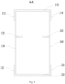
Fig. 5 is a schematic structural diagram of a cross-sectional view along A-A inFig. 4 ; -
Fig. 6 is a schematic structural diagram of a cross-sectional view along B-B inFig. 4 ; -
Fig. 7 is a three-dimensional schematic structural diagram of a partial frame structure of a boom of an embodiment of the present invention; -
Fig. 8 is a three-dimensional schematic structural diagram of a partial frame structure of a boom according to other embodiments of the present invention; -
Fig. 9 is a front view schematic structural diagram of a boom located at a terminal position of a boom system according to some embodiments of the present invention; -
Fig. 10 is a side view schematic structural diagram of a boom located at a terminal position of a boom system according to some embodiments of the present invention; -
Fig. 11 is a three-dimensional schematic structural diagram of a first connecting portion of a boom according to some embodiments of the present invention; -
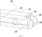
Fig. 12 is a three-dimensional schematic structural diagram of a middle body of a boom according to some embodiments of the present invention; and -
Fig. 13 is a three-dimensional schematic structural diagram of a second connecting portion of a boom according to some embodiments of the present invention. - The corresponding relationship between the reference signs and component names in
Figs. 1 and 2 is as follows:
100' integral carbon fiber boom, 100" carbon fiber boom. - The corresponding relationship between the reference signs and component names in
Figs. 3 to 13 is as follows:
100 boom, 102 middle body, 104 first connecting portion, 106 second connecting portion, 108 fixing part, 110 top plate, 112 first bending portion, 114 second bending portion, 116 first clamping slot, 118 second clamping slot, 120 bottom plate, 122 third bending portion, 124 fourth bending portion, 126 third clamping slot, 128 fourth clamping slot, 130 first side plate, 132 first rib plate, 140 second side plate, 142 second rib plate, 150 axle sleeve, 160 first plate body, 162 second plate body, 164 third plate body, 170 first steel guard plate, 172 second steel guard plate, 180 oil cylinder mounting seat, 190 support member, 192 support frame, 194 support bracket. - In order to understand the above-mentioned objects, features and advantages of the present invention more clearly, the present invention will be described in further detail with reference to the accompanying drawings and detailed description. It should be noted that the embodiments and features in the embodiments of the present invention may be combined with one another without conflicts.
- In the following description, numerous specific details are set forth in order to provide a thorough understanding of the present invention, but the present invention may be practiced otherwise than as described herein, within the scope defined by the appended claims.
- In a related art, most of the booms of concrete pump trucks are mainly steel structures, but there is little room for the development of high-strength steel structures. The research on lightweight boom is mainly based on carbon fiber composite materials and aluminum alloys, but the current research on both is mainly based on the integral molding of a single material, such as the boom of pure carbon fiber composite material, the boom of carbon fiber foam sandwich composite material and the boom 100' of integral carbon fiber as shown in
Fig. 1 . The production method of the boom of carbon fiber composite material comprises inflating a retractable air bag to form an air bag with a first state, and laying the carbon fiber prepreg on its outer surface to obtain the component, put it into the box mold and inflate the airbag, and then compress and shape the carbon fiber prepreg to obtain the second transition component. The second transition component is heated and solidified, and after solidification, the carbon fiber boom is obtained by cooling and demoulding. The cost of this integral carbon fiber boom 100' is relatively expensive, resulting in a higher cost of the boom and lower cost performance. Moreover, the mold used for the integrally formed boom model is complex and expensive, and the investment in the pre-process verification is too large. Each structural optimization requires re-adjustment of the mold, which is also extremely disadvantageous for the cost of later mass production. - In another related art, as shown in
Fig. 2 , acarbon fiber boom 100" for a concrete pump truck is provided with an outer mold, and the outer mold is composed of an upper mold and a lower mold and has a hollow structure. The carbon fiber prepreg for makingcarbon fiber boom 100" is spread on the inner surfaces of the upper and lower molds. The mechanical properties and size of the composite material boom have extremely high requirements on mold tooling and process, which will lead to process instability. Thereby, problems such as internal defects occur, and there are problems with the connection strength of steel structural parts, aluminum structural parts and carbon fiber composite structural parts. - The technical solutions of some embodiments of the present invention are described below with reference to
Figs. 3 to 13 . - As shown in
Figs. 3 to 6 , this embodiment provides aboom 100 comprising a frame structure, wherein theboom 100 comprises: atop plate 110; abottom plate 120, wherein thebottom plate 120 and thetop plate 110 are oppositely disposed at an interval; afirst side plate 130; and asecond side plate 140, wherein thesecond side plate 140 and thefirst side plate 130 are oppositely disposed at an interval. A first side of thetop plate 110 is provided with afirst bending portion 112, and at least a portion of thefirst bending portion 112 and a first end of thefirst side plate 130 are attached and spliced to each other, a second side of thetop plate 110 opposite to thefirst bending portion 112 is provided with asecond bending portion 114, at least a portion of thesecond bending portion 114 and a first end of thesecond side plate 140 are attached and spliced to each other, and a first side of thebottom plate 120 is provided with athird bending portion 122, at least a portion of thethird bending portion 122 and a second end of thefirst side plate 130 are attached and spliced to each other, a second side of thebottom plate 120 opposite to thethird bending portion 122 is provided with afourth bending portion 124, at least a portion of thefourth bending portion 124 and a second end of thesecond side plate 140 are attached and spliced to each other, and define the frame structure. - In this embodiment, the
top plate 110, thebottom plate 120, thefirst side plate 130 and thesecond side plate 140 are all plate body structures, thetop plate 110 and thebottom plate 120 with the same thickness can give full play to the compression resistance and the tensile strength properties of thebottom plate 120 and thetop plate 110. Wherein the corresponding mounting holes are machined on thefirst side plate 130 and thesecond side plate 140 according to the use requirements of theboom 100, to install the relevant parts. For example, the mounting holes are used for mounting theaxle sleeve 150, the oil cylinder, and the like. The shape of thebottom plate 120 is adapted to one side of thefirst side plate 130 away from thetop plate 110 and one side of thesecond side plate 140 away from thetop plate 110. Since the body of thetop plate 110 is a flat plate structure, thefirst bending portion 112 and thesecond bending portion 114 respectively form an included angle with the body of thefirst side plate 130 and the body of thesecond side plate 140, and the included angle is 90°. Therefore, thefirst bending portion 112 and thesecond bending portion 114 can attach to the first end of thefirst side plate 130 and the first end of thesecond side plate 140, respectively. In order to attach thethird bending portion 122 and thefourth bending portion 124 to the second end of thefirst side plate 130 and the second end of thesecond side plate 140, respectively, to realize the firmness of the connection structure, thethird bending portion 122 and thefourth bending portion 124 can match the shape of thebottom plate 120. Thetop plate 110, thebottom plate 120, thefirst side plate 130 and thesecond side plate 140 are spliced together to assemble the frame structure ofboom 100. Compared with theboom 100 with an integral structure, the cost of making the mold of theboom 100 is reduced, and the production efficiency of theboom 100 is improved at the same time. In addition, the splicing structure is more conducive to realizing the interconnection between different materials. For example, when the materials of thefirst side plate 130 and thesecond side plate 140 are different from that of thebottom plate 120 or thetop plate 110, the frame structure of theboom 100 can be easily assembled by splicing together the structure group. Thereby, the connection cost of the interconnection can be reduced and the molding efficiency of theboom 100 can be improved. - In addition, in order to further increase the integral structural strength of the
boom 100, thefirst side plate 130 and thesecond side plate 140 are both straight plates. The opposite sides of thetop plate 110 are spliced with the first end of thefirst side plate 130 and the first end of thesecond side plate 140 respectively. The opposite sides of thebottom plate 120 are spliced with the second end of thefirst side plate 130 and the second end of thesecond side plate 140 respectively, which is simpler during splicing, and facilitates the installation of the fixingpart 108, so that the spliced frame structure is more stable. Wherein, the fixingpart 108 may be a U-shaped fixing piece, so that at least a portion of thetop plate 110 is clamped in the groove of the fixing piece, so that a fastener such as a screw can be used between the middle portion of the fixing piece and thetop plate 110 to further strengthen. And the two sides of the fixing piece can be fixed with thefirst side plate 130 and thesecond side plate 140 by fasteners such as screws, so as to further improve the integral structural stability of theboom 100. - The
top plate 110 and thebottom plate 120 are bonded and mechanically connected with thefirst side plate 130 and thesecond side plate 140, respectively. Thefirst side plate 130 and thetop plate 110 and thebottom plate 120, as well as thesecond side plate 140 and thetop plate 110 and thebottom plate 120, are connected by bonding and mechanical connection. Wherein, the mechanical connection is fastener connection or riveting, and the fastener connection can be screw connection, bolt connection, etc. Specifically, the opposite sides of thetop plate 110 are respectively bonded with the first end of thefirst side plate 130 and the first end of thesecond side plate 140, and then connected by fasteners. Similarly, the opposite sides of thebottom plate 120 are respectively bonded to the second end of thefirst side plate 130 and the second end of thesecond side plate 140, and then connected by fasteners. - As shown in
Figs. 5 to 8 , this embodiment provides aboom 100. In addition to the technical features of the above-mentioned embodiments, this embodiment also comprises the following technical features. - The
first bending portion 112 and thesecond bending portion 114 are respectively integrally formed with thetop plate 110, and both face thebottom plate 120, thethird bending portion 122 and thefourth bending portion 124 are respectively integrally formed with thebottom plate 120, and both face thetop plate 110. - In this embodiment, the
first bending portion 112 and thesecond bending portion 114 are integrally formed with thetop plate 110, respectively, and thethird bending portion 122 and thefourth bending portion 124 are integrally formed with thebottom plate 120, respectively. The forming process of the top plate and the bottom plate is simplified, the forming efficiency of bottom plate and the top plate is improved, and the forming efficiency of the boom is further improved. Since thefirst side plate 130 and thesecond side plate 140 are respectively straight plates, the first end of thefirst side plate 130 and thefirst bending portion 112 are spliced to each other, and the second end of thefirst side plate 130 and thethird bending portion 122 are spliced to each other. Similarly, the first end of thesecond side plate 140 and thesecond bending portion 114 are spliced to each other, and the second end of thesecond side plate 140 and thefourth bending portion 124 are spliced to each other, so that thetop plate 110, thebottom plate 120, thefirst side plate 130 and thesecond side plate 140 are spliced to form theboom 100. The structure of theboom 100 spliced in this way is more stable and firm, which can improve the structural strength of theboom 100. - In this embodiment, specifically, the first end of the
first side plate 130 is attached to thefirst bending portion 112, and the first end of thesecond side plate 140 is attached to thesecond bending portion 114. The second end of thefirst side plate 130 is attached to thethird bending portion 122, and the second end of thesecond side plate 140 is attached to thefourth bending portion 124. Thefirst bending portion 112 and thesecond bending portion 114 make the cross section of thetop plate 110 U-shaped, so that the first end of thefirst side plate 130 can be attached to the inner side of thefirst bending portion 112, and the first end of thesecond side plate 140 can be attached to the inner side of thesecond bending portion 114. Similarly, thethird bending portion 122 and thefourth bending portion 124 make the cross section of thebottom plate 120 U-shaped. The second end of thefirst side plate 130 is attached to the inner side of thethird bending portion 122, and the second end of thesecond side plate 140 is attached to the inner side of thefourth bending portion 124. Theboom 100 is then spliced out by bonding, welding, riveting and/or fastener connections, etc., which can further increase the structural strength of theboom 100. - In addition, as shown in
Fig. 8 , thefirst bending portion 112 and thesecond bending portion 114 make the cross section of the top plate 110 T-shaped. Similarly, thethird bending portion 122 and thefourth bending portion 124 make the cross section of the bottom plate 120 T-shaped. Taking thefirst bending portion 112 as an example, there is a gap between the outer side surface of thefirst bending portion 112 and the edge of the top plate body, the first end of thefirst side plate 130 is located in the gap and is attached to the outer side of thefirst bending portion 112, which is more convenient for the connection and fixation of thefirst side plate 130 and thesecond side plate 140. In addition, in order to facilitate the installation of the fixingpart 108, thefirst side plate 130 will not protrude from the edge of thetop plate 110. Similarly, thesecond bending portion 114, thethird bending portion 122 and thefourth bending portion 124 are also arranged. - In this embodiment, the
first bending portion 112 and thesecond bending portion 114 are respectively provided integrally with thetop plate 110, and thefirst bending portion 112 and thesecond bending portion 114 respectively form an included angle with the body of thetop plate 110, and the included angle is 90°. Similarly, thethird bending portion 122 and thefourth bending portion 124 are respectively provided integrally with thebottom plate 120, and thethird bending portion 122 and thefourth bending portion 124 respectively form an included angle with the body of thebottom plate 120, and the included angle is 90°. - As shown in
Figs. 5 to 8 , this embodiment provides aboom 100. In addition to the technical features of the above-mentioned embodiments, this embodiment also comprises the following technical features. - The
first bending portion 112 and thesecond bending portion 114 are respectively connected with the first end of thefirst side plate 130 and the first end of thesecond side plate 140 in a rivet bonding connection, thethird bending portion 122 and thefourth bending portion 124 are respectively connected with the second end of thefirst side plate 130 and the second end of thesecond side plate 140 in a rivet bonding connection. - In this embodiment, the
first bending portion 112 and thethird bending portion 122 are respectively spliced with the opposite ends of thefirst side plate 130, and thesecond bending portion 114 and thefourth bending portion 124 are respectively spliced with the opposite ends of thesecond side plate 140. Their splicing structure is a mixed connection method of gluing and riveting. It can play the role of fast connection and can improve the splicing speed ofboom 100. In addition, the connection method of the rivet bonding connection can also be, firstly gluing, which can not only play the role of connection, but also can quickly locate; and then riveting is carried out, which can further improve the splicing speed and the splicing quality of the integral boom. - As show in
Fig. 7 , this embodiment provides aboom 100. In addition to the technical features of the above-mentioned embodiments, this embodiment also comprises the following technical features. - The
boom 100 also comprises afirst clamping slot 116, asecond clamping slot 118, athird clamping slot 126 and afourth clamping slot 128. Thefirst clamping slot 116 is provided on an end surface of thefirst bending portion 112 facing thebottom plate 120; thesecond clamping slot 118 is provided on an end surface of thesecond bending portion 114 facing thebottom plate 120; thethird clamping slot 126 is provided on an end surface of thethird bending portion 122 facing thetop plate 110; and thefourth clamping slot 128 is provided on an end surface of thefourth bending portion 124 facing thetop plate 110, wherein, opposite ends of thefirst side plate 130 are respectively clamped with thefirst clamping slot 116 and thethird clamping slot 126, opposite ends of thesecond side plate 140 are respectively clamped with thesecond clamping slot 118 and thefourth clamping slot 128. - In this embodiment, at least a portion of one side of the
first side plate 130 is clamped in thefirst clamping slot 116, and at least a portion of another side of thefirst side plate 130 is clamped in thethird clamping slot 126. Similarly, at least a portion of one side of thesecond side plate 140 is clamped in thesecond clamping slot 118, and at least a portion of another side of thesecond side plate 140 is clamped in thefourth clamping slot 128. Therefore, taking the installation of thefirst side plate 130 as an example, thefirst clamping slot 116 and thethird clamping slot 126 can play a limiting role on both ends of thefirst side plate 130, to help define the position of thefirst side plate 130. Then, thefirst side plate 130 is fixed by welding, riveting, fastener connection, etc. It can be seen that thefirst clamping slot 116 and thethird clamping slot 126 can not only make the installation of thefirst side plate 130 more convenient, but also make the connection structure between thefirst side plate 130 and thetop plate 110 and thebottom plate 120 more stable. Similarly, the installation of thesecond side plate 140 is the same; therefore, the integral structural strength of theboom 100 can be further increased. - As shown in
Fig. 3 ,Fig. 4 ,Fig. 9 ,Fig. 10 ,Fig. 11, Fig. 12 andFig. 13 , this embodiment provides aboom 100. In addition to the technical features of the above-mentioned embodiments, this embodiment also comprises the following technical features. - The
boom 100 also comprises amiddle body 102, a first connectingportion 104 and a second connectingportion 106. The first connectingportion 104 is provided at one end themiddle body 102 in a length direction and protruding out of themiddle body 102; the second connectingportion 106 is provided at the other end of the middle body in a length direction, wherein a thickness of themiddle body 102 gradually decreases from the first connectingportion 104 to the second connectingportion 106, a thickness of the second connectingportion 106 is equal to a thickness of one end of themiddle body 102 away from the first connectingportion 104. - In this embodiment, one of the
boom 100 located in the boom system needs at least one end to be articulated with theadjacent boom 100. Therefore, eachboom 100 in the boom system comprises a first connectingportion 104, amiddle body 102 and a second connectingportion 106. There is no doubt that theboom 100 located in the middle of the boom system needs two hinged ends, while theboom 100 located at the terminal may only need one hinged end. Therefore, the specific structures of themultiple booms 100 that make up the boom system are not the same. - As shown in
Figs. 3 and4 , when both the first connectingportion 104 and the second connectingportion 106 need to be used as hinged ends, that is, the specific structure of theboom 100 located in the middle is that thefirst side plate 130 and thesecond side plate 140 respectively extend from themiddle body 102 in a direction away from the second connectingportion 106 and in a direction away from thetop plate 110 with a lug structure. Therefore, one side of thefirst side plate 130 and one side of thesecond side plate 140 located at the first connectingportion 104 away from thetop plate 110 are arc-shaped, and thebottom plate 120 located at the first connectingportion 104 is also arc-shaped. Then, thethird bending portion 122 and thefourth bending portion 124 located at the first connectingportion 104 are also arc-shaped. Thefirst side plate 130 and thesecond side plate 140 of themiddle body 102 are provided with an oilcylinder mounting seat 180 at one end away from thetop plate 110. The oilcylinder mounting seat 180 comprises two cylinder mounting holes provided on thefirst side plate 130 and thesecond side plate 140, and the two cylinder mounting holes are arranged opposite to each other for mounting the cylinder. When in the boom system, the head and tail ofmultiple booms 100 are hinged to each other, and the extension and folding of the boom system are realized through the oil cylinder. Wherein, the first connectingportion 104 and the second connectingportion 106 are used as the hinged connection ends to realize the hinged connection between the twoadjacent booms 100 or to realize the connection with the external components and the working equipment respectively. Correspondingly, on theboom 100 where the oilcylinder mounting seat 180 needs to be set, thebottom plate 120 can be divided into two parts, as shown inFig. 3 . On theboom 100 located at the terminal of the boom system without setting the oilcylinder mounting seat 180, as shown inFig. 7 , thebottom plate 120 can extend from the first connectingportion 104 to the second connectingportion 106. - In addition, in order to increase the structural strength of the first connecting
portion 104, steel plate reinforcement is also required. For example, a firststeel guard plate 170 is provided on top of the first connectingportion 104, and both sides of the firststeel guard plate 170 are connected with thefirst side plate 130 and thesecond side plate 140, respectively. The bottom of the first connectingportion 104 is provided with a secondsteel guard plate 172, and the secondsteel guard plate 172 is connected with thebottom plate 120. - As shown in
Figs. 9 and10 , when the second connectingportion 106 is not used as a hinged end, but needs to be connected with a pre-working equipment or an external component, it does not need to carry a large weight, and there is no need to set the oilcylinder mounting seat 180 on theboom 100 used as a terminal. Therefore, as shown inFigs. 8 and9 , in order to further reduce the weight of theboom 100, the thickness of the first connectingportion 104 in theboom 100 used in the boom system at the terminal can be made smaller. However, the thickness of the first connectingportion 104 of theboom 100 used as the hinged end is relatively large. In addition, the thickness of themiddle body 102 is gradually reduced from the first connectingportion 104 to the second connectingportion 106, which can save the usage of thefirst side plate 130 and thesecond side plate 140, and can further reduce the weight. The thickness of the second connectingportion 106 is equal to one end of themiddle body 102 away from the first connectingportion 104, the structure is simple, the production is convenient, and the production process can be simplified. - As shown in
Fig. 3 , this embodiment provides aboom 100. In addition to the technical features of the above-mentioned embodiments, this embodiment also comprises the following technical features. - The
first side plate 130 and thesecond side plate 140 both comprise afirst plate body 160, asecond plate body 162 and athird plate body 164. Thefirst plate body 160 is provided at one end of thefirst side plate 130 or one end of thesecond side plate 140 in a length direction, thesecond plate body 162 is disposed with thefirst plate body 160 side by side; and thethird plate body 164 is provided at the other end of thefirst side plate 130 or the other end of thesecond side plate 140 in a length direction, wherein thicknesses of thefirst plate body 160 and thethird plate body 164 are respectively greater than a thickness of thesecond plate body 162, thesecond plate body 162 is respectively connected with thefirst plate body 160 and thethird plate body 164 on opposite sides in a length direction by friction welding, to splice out thefirst side plate 130 or thesecond side plate 140. - In this embodiment, since the
first side plate 130 and thesecond side plate 140 comprise thefirst plate body 160, thesecond plate body 162 and thethird plate body 164, thefirst plate body 160 is a lug plate structure. The lug structure increases the thickness of the first connectingportion 104, thus, the structural strength of the first connectingportion 104 can be improved. - The
first side plate 130 or thesecond side plate 140 of theboom 100 as the middle hinged end is welded by thefirst plate body 160, thesecond plate body 162 and thethird plate body 164 by friction stir welding. Since thefirst plate body 160 is located at the end portion of the first end of thefirst side plate 130 or thesecond side plate 140, that is, thefirst plate body 160 is located at the first connectingportion 104. Therefore, the thickness of thefirst plate body 160 is greater than that of thesecond plate body 162, so as to enhance the structural strength and make the first connectingportion 104 play a better connection role. The thickness of thethird plate body 164 is greater than that of thesecond plate body 162, so that the second connectingportion 106 can play a better connection role. The inner surface of thefirst plate body 160, the inner surface of thesecond plate body 162 and the inner surface of thethird plate body 164 are located in the same plane, that is, the outer surface of thefirst plate body 160 and the outer surface of thethird plate body 164 both protrude from the outer surface of thesecond plate body 162. It is convenient to install theaxle sleeve 150 on the first connectingportion 104 and the second connectingportion 106, which makes the connection between the twoadjacent booms 100 more convenient. Friction welding is a method of using the heat generated by the mutual movement and friction of the end surfaces of the work piece to make the end portion reach a thermoplastic state, and then quickly upsetting to complete the welding. Friction stir welding is a kind of friction welding, and friction stir welding also uses friction heat and plastic deformation heat as welding heat sources. The difference between it and ordinary friction welding is that the welding process of friction stir welding is that a stirring needle of a cylinder or other shape (such as a threaded cylinder) is inserted into the joint of the work piece, and the high-speed rotation of the welding head makes it rub against the welding work piece material, so that the temperature of the material at the connecting portion increases and softens. Thefirst plate body 160, thesecond plate body 162 and thethird plate body 164 are connected by friction stir welding, which can ensure the integral structural strength of the first side plate or the second side plate. - The
boom 100 also comprises anaxle sleeve 150, which is also connected by friction welding with thefirst side plate 130 and/or thesecond side plate 140. Theaxle sleeve 150 is used to install the hinged axle to connect the twoadjacent booms 100. - As shown in
Fig. 5 , this embodiment provides aboom 100. In addition to the technical features of the above-mentioned embodiments, this embodiment also comprises the following technical features. - The
boom 100 further comprises afirst rib plate 132 and asecond rib plate 142. Thefirst rib plate 132 is provided on a surface of thefirst side plate 130 facing thesecond side plate 140, and thefirst rib plate 132 is located between thefirst bending portion 112 and thethird bending portion 122; and thesecond rib plate 142 is provided on a surface of thesecond side plate 140 facing thefirst side plate 130, and thesecond rib plate 142 is located between thesecond bending portion 114 and thefourth bending portion 124. - In this embodiment, the
first rib plate 132 is arranged along the length direction of thefirst side plate 130, and thesecond rib plate 142 is arranged along the length direction of thesecond side plate 140, so as to be able to increase the structural strength of thefirst side plate 130 and thesecond side plate 140, respectively. - As shown in
Fig. 6 , this embodiment provides aboom 100. In addition to the technical features of the above-mentioned embodiments, this embodiment also comprises the following technical features. - The
boom 100 further comprises asupport member 190, arranged in the frame structure, wherein thesupport member 190 comprises asupport frame 192, the support frame comprises four edge frames and four inner corners, and the four edge frames are adapted to abut with thetop plate 110, thebottom plate 120, thefirst side plate 130 and thesecond side plate 140 respectively; and asupport bracket 194, comprising two mutually intersecting support plates to be supported on the four inner corners of thesupport frame 192. - In this embodiment, the
support member 190 can be made of steel plate, and one ormore support members 190 can be arranged in the frame structure of theboom 100. Thesupport member 190 is supported in the frame structure through thesupport frame 192, and the support for the frame structure is further increased by thesupport bracket 194, which can increase the integral structural strength of theboom 100. - This embodiment provides a
boom 100. In addition to the technical features of the above-mentioned embodiments, this embodiment also comprises the following technical features. - The
top plate 110 and thebottom plate 120 are carbon fiber plates respectively, and thefirst side plate 130 and thesecond side plate 140 are aluminum alloy plates respectively. - In this embodiment, 7-series aluminum alloys are selected as the
top plate 110 and thebottom plate 120, wherein, 7-series aluminum alloys are a common alloy in aluminum alloys, comprising zinc and magnesium. The weight of aluminum alloy is lighter than that of steel plate. Therefore, theboom 100 assembled by splicing carbon fiber plate and aluminum alloy plate not only reduces the weight, but also ensures the compression resistance performance ofboom 100. And compared with theboom 100 made of pure carbon fiber material, the cost of raw materials is reduced. The welding of aluminum alloys has not received attention in the engineering field, especially the 7 series aluminum alloys, the present invention boldly adopts the friction stir welding process of the 7-series aluminum alloys. In addition, by using the combination of 7-series aluminum alloy and carbon fiber sheet, the cost of the mold forboom 100 is also greatly reduced. At the same time, compared with the carbon fiber boom made as a whole, it also improves the molding efficiency of theboom 100. - This embodiment provides a working equipment, which can be a concrete delivery pump truck, a fire truck, a crane, a placing boom, and the like. The working equipment comprises a chassis and a boom system, and the boom system is arranged on the chassis; wherein, the boom system comprises the
boom 100 in any one of the embodiments, and twoadjacent booms 100 are hinged to each other. - In this embodiment, the boom system is composed of
multi-section boom 100, connecting rod, oil cylinder and connecting piece, etc. Theboom 100 located at one end of the boom system is connected with the chassis. Thus, the boom system has the beneficial effects of theboom 100 in any one of the embodiments. When the working equipment is working, the boom system is unfolded and extended under the drive of the hydraulic cylinder to transport concrete. During the driving process of the working equipment, the boom system needs to be folded and placed on the vehicle body. Therefore, under the action of the telescopic rod of the oil cylinder, the working equipment has a foldable or telescopic boom system. The working equipment in this embodiment can be a concrete mixer or the like. - To sum up, the beneficial effects of the embodiments of the present invention are:
- 1. By splicing the opposite sides of the
top plate 110 and thebottom plate 120 with thefirst side plate 130 and thesecond side plate 140, respectively, aboom 100 with a frame structure is defined. As a result, theboom 100 has higher strength, more stable integral structure, and is suitable for mass production. Compared with the integral molding mold, a variety of simple molds are used, and the cost of later design changes is low. - 2. By using carbon fiber plates as the
top plate 110 and thebottom plate 120, and using aluminum alloy plates or profiles as thefirst side plate 130 and thesecond side plate 140, the cost of raw materials and molds is lower than that of pure carbon fiber boom. Compared with steel boom, the weight is reduced by more than 35%, the stress amplitude is reduced by more than 50%, and the rigidity is reduced by less than 10%. - 3. The post-maintenance difficulty and cost of the spliced
boom 100 are much lower than those of the boom formed by integral molding of carbon fiber composite materials. - In the present invention, the terms "first", "second", and "third" are used for the purpose of description only, and cannot be understood as indicating or implying relative importance; and the term "plurality" means two or more, unless otherwise expressly defined. The terms "installing", "connected", "connection", "fixing" and the like should be understood in a broad sense. For example, "connection" may be a fixed connection, a removable connection or an integral connection; and "connected" may refer to direct connection or indirect connection through an intermediary. A person of ordinary skills in the art could understand the specific meaning of the terms in the present invention according to specific situations.
- In the description of the present invention, it should be understood that the orientation or position relationships indicated by the terms "upper", "lower", "left", "right", "front", "back" and the like are the orientation or position relationships based on what is shown in the drawings, are merely for the convenience of describing the present invention and simplifying the description, and do not indicate or imply that the device or unit referred to must have a particular direction and is constructed and operated in a specific orientation, and thus cannot be understood as the limitation of the present invention.
- In the description of the present specification, the descriptions of the terms "one embodiment", "some embodiments" and "specific embodiments" and the like mean that specific features, structures, materials or characteristics described in conjunction with the embodiment(s) or example(s) are comprised in at least one embodiment or example of the present invention. In the specification, the schematic representation of the above terms does not necessarily refer to the same embodiment or example. Moreover, the specific features, structures, materials or characteristics described may be combined in a suitable manner in any one or more embodiments or examples.
Claims (6)
- A boom (100) of a working equipment, wherein the boom (100) comprises:a frame structure;a top plate (110);a bottom plate (120), wherein the bottom plate (120) and the top plate (110) are oppositely disposed at an interval;a first side plate (130); anda second side plate (140), wherein the second side plate (140) and the first side plate (130) are oppositely disposed at an interval,wherein a first side of the top plate (110) is provided with a first bending portion (112), at least a portion of the first bending portion (112) and a first end of the first side plate (130) are attached and spliced to each other, a second side of the top plate (110) opposite to the first bending portion (112) is provided with a second bending portion (114), at least a portion of the second bending portion (114) and a first end of the second side plate (140) are attached and spliced to each other; and a first side of the bottom plate (120) is provided with a third bending portion (122), at least a portion of the third bending portion (122) and a second end of the first side plate (130) are attached and spliced to each other, a second side of the bottom plate (120) opposite to the third bending portion (122) is provided with a fourth bending portion (124), at least a portion of the fourth bending portion (124) and a second end of the second side plate (140) are attached and spliced to each other, and define the frame structure;. whereinthe first bending portion (112) and the second bending portion (114) are respectively integrally formed with the top plate (110), and both face the bottom plate (120),the third bending portion (122) and the fourth bending portion (124) are respectively integrally formed with the bottom plate (120), and both face the top plate (110); whereinthe first bending portion (112) and the second bending portion (114) are respectively connected with the first end of the first side plate (130) and the first end of the second side plate (140),the third bending portion (122) and the fourth bending portion (124) are respectively connected with the second end of the first side plate (130) and the second end of the second side plate (140);the boom (100) further comprising:a first clamping slot (116), provided on an end surface of the first bending portion (112) facing the bottom plate (120);a second clamping slot (118), provided on an end surface of the second bending portion (114) facing the bottom plate (120);a third clamping slot (126), provided on an end surface of the third bending portion (122) facing the top plate (110); anda fourth clamping slot (128), provided on an end surface of the fourth bending portion (124) facing the top plate (110),the boom (100) being characterised in that, the boom (100) is part of a concrete pump;and in that the first (112) and second bending portions (114) are connected in a rivet bonding connection,and in that the third (122) and fourth bending portions (124) are connected in a rivet bonding connection,and in that two opposite ends of the first side plate (130) are respectively clamped with the first clamping slot (116) and the third clamping slot (126),two opposite ends of the second side plate (140) are respectively clamped with the second clamping slot (118) and the fourth clamping slot (128), and in thatthe top plate (110) and the bottom plate (120) are respectively carbon fiber plates, and the first side plate (130) and the second side plate (140) are respectively aluminum alloy plates.
- The boom (100) according to claim 1, further comprising:a middle body (102);a first connecting portion (104), provided at one end the middle body (102) in a length direction and protruding out of the middle body (102); anda second connecting portion (106), provided at the other end of the middle body (102) in a length direction,wherein a thickness of the middle body (102) gradually decreases from the first connecting portion (104) to the second connecting portion (106), a thickness of the second connecting portion (106) is equal to a thickness of one end of the middle body (102) away from the first connecting portion (104).
- The boom (100) according to claim 2, wherein the first side plate (130) and the second side plate (140) both comprises:a first plate body (160), provided at one end of the first side plate (130) or one end of the second side plate (140) in a length direction,a second plate body (162), disposed with the first plate body side by side (160); anda third plate body (164), provided at the other end of the first side plate (130) or the other end of the second side plate (140) in a length direction,wherein thicknesses of the first plate body (160) and the third plate body (164) are respectively greater than a thickness of the second plate body (162), the second plate body (162) is respectively connected with the first plate body (160) and the third plate body (164) on opposite sides in a length direction by friction welding, to splice out the first side plate (130) or the second side plate (140).
- The boom (100) according to any one of claims 1 to 3, further comprising:a first rib plate (132), provided on a surface of the first side plate (130) facing the second side plate (140), and the first rib plate (132) being located between the first bending portion (112) and the third bending portion (122); anda second rib plate (142), provided on a surface of the second side plate (140) facing the first side plate (130), and the second rib plate (142) being located between the second bending portion (114) and the fourth bending portion (124).
- The boom (100) according to any one of claims 1 to 4, further comprising: a support member (190), arranged in the frame structure, wherein the support member (190) comprises:a support frame (192), the support frame (192) comprises four edge frames and four inner corners, and the four edge frames are adapted to abut with the top plate (110), the bottom plate (120), the first side plate (130) and the second side plate (140) respectively; anda support bracket (194), comprising two mutually intersecting support plates to be supported on the four inner corners of the support frame (192).
- A working equipment being a concrete pump truck, comprising:a chassis; anda boom system, provided on the chassis,wherein the boom system comprises a plurality of booms (100) according to any one of claims 1 to 5, and two adjacent booms (100) are hinged to each other.
Applications Claiming Priority (2)
| Application Number | Priority Date | Filing Date | Title |
|---|---|---|---|
| CN202010162108.6A CN111173287B (en) | 2020-03-10 | 2020-03-10 | Booms and operating equipment |
| PCT/CN2020/112051 WO2021179546A1 (en) | 2020-03-10 | 2020-08-28 | Boom and working equipment |
Publications (3)
| Publication Number | Publication Date |
|---|---|
| EP4119743A1 EP4119743A1 (en) | 2023-01-18 |
| EP4119743A4 EP4119743A4 (en) | 2024-04-17 |
| EP4119743B1 true EP4119743B1 (en) | 2025-02-26 |
Family
ID=70655096
Family Applications (1)
| Application Number | Title | Priority Date | Filing Date |
|---|---|---|---|
| EP20923993.8A Active EP4119743B1 (en) | 2020-03-10 | 2020-08-28 | Boom and working equipment |
Country Status (4)
| Country | Link |
|---|---|
| US (1) | US12595670B2 (en) |
| EP (1) | EP4119743B1 (en) |
| CN (1) | CN111173287B (en) |
| WO (1) | WO2021179546A1 (en) |
Families Citing this family (4)
| Publication number | Priority date | Publication date | Assignee | Title |
|---|---|---|---|---|
| CN111335638A (en) * | 2020-03-10 | 2020-06-26 | 三一汽车制造有限公司 | Booms and work equipment |
| CN111173287B (en) * | 2020-03-10 | 2024-05-28 | 三一汽车制造有限公司 | Booms and operating equipment |
| DE202023101065U1 (en) * | 2023-03-07 | 2024-06-10 | Liebherr-Mischtechnik Gmbh | Distributor boom arm |
| DE202023103230U1 (en) | 2023-06-13 | 2024-09-17 | Liebherr-Mischtechnik Gmbh | distribution boom arm |
Family Cites Families (39)
| Publication number | Priority date | Publication date | Assignee | Title |
|---|---|---|---|---|
| US790478A (en) * | 1905-01-28 | 1905-05-23 | Vulcan Iron Works Company | Boom for excavators. |
| DE2317595A1 (en) | 1973-04-07 | 1974-10-31 | Kaspar Klaus | TELESCOPIC UNIT, IN PARTICULAR FOR LIFTING EQUIPMENT |
| US4216895A (en) * | 1977-10-21 | 1980-08-12 | J. I. Case Company | Method of forming hollow boom |
| GB2246111B (en) * | 1990-07-13 | 1994-05-04 | Samsung Heavy Ind | Dipper stick for excavator of high strength polymeric composite materials and method for manufacturing such |
| AU2001253000A1 (en) * | 2000-03-28 | 2001-10-08 | David J. Higgins | Telescoping boom |
| US6719009B1 (en) * | 2001-02-23 | 2004-04-13 | Schwing America, Inc. | Composite material piping system |
| US6755212B1 (en) * | 2001-02-23 | 2004-06-29 | Schwing America, Inc. | Boom stiffening system |
| US6786233B1 (en) | 2001-02-23 | 2004-09-07 | Schwing America, Inc. | Boom utilizing composite material construction |
| US6698451B2 (en) * | 2001-02-23 | 2004-03-02 | Schwing America, Inc. | Conveying pipeline mounted inside a boom |
| US7165929B2 (en) * | 2001-12-20 | 2007-01-23 | Caterpillar Inc | Load bearing member arrangement and method |
| US20030118432A1 (en) * | 2001-12-20 | 2003-06-26 | Lee Christy L. | Method and apparatus for reinforcing a load bearing member |
| GB2387373A (en) | 2002-04-12 | 2003-10-15 | Bamford Excavators Ltd | Composite boom for a load handling machine |
| JP2004124357A (en) * | 2002-08-02 | 2004-04-22 | Kobelco Contstruction Machinery Ltd | Boom structure and manufacturing method of boom member |
| US8505184B2 (en) * | 2009-03-13 | 2013-08-13 | Cifa Spa | Method to make an arm for the distribution of concrete, and arm thus made |
| CN101666162A (en) * | 2009-10-09 | 2010-03-10 | 三一重工股份有限公司 | Joint arm of cloth arm bracket and manufacturing method thereof as well as concrete conveying machine |
| DE202010014103U1 (en) | 2010-10-08 | 2012-01-10 | Liebherr-Werk Ehingen Gmbh | Boom element, telescopic boom and construction vehicle |
| IT1404177B1 (en) * | 2011-02-23 | 2013-11-15 | Cifa Spa | PROCEDURE FOR THE REALIZATION OF ARMS IN COMPOSITE MATERIAL FOR THE DISTRIBUTION OF CONCRETE AND ARM, SO OBTAINED. |
| ITMI20110862A1 (en) | 2011-05-17 | 2012-11-18 | Cifa Spa | TELESCOPIC ARM FOR CRANES AND CRANE INCLUDING SUCH ARM |
| US9290363B2 (en) * | 2011-07-21 | 2016-03-22 | Manitowoc Crane Companies, Llc | Tailor welded panel beam for construction machine and method of manufacturing |
| CN202248920U (en) * | 2011-09-28 | 2012-05-30 | 中联重科股份有限公司 | Concrete pump truck boom and concrete pump truck |
| CN102493651B (en) * | 2011-11-30 | 2013-08-21 | 中联重科股份有限公司 | Concrete equipment and arm support thereof |
| CN202645013U (en) | 2012-03-09 | 2013-01-02 | 三一重工股份有限公司 | Preload reinforced boom and outrigger and pump truck |
| CN102535857B (en) * | 2012-03-21 | 2015-07-01 | 三一重工股份有限公司 | Box beam, arm support, outrigger and engineering machine |
| CN102705330B (en) * | 2012-06-13 | 2015-01-07 | 中联重科股份有限公司 | Pin shaft, pin shaft installation structure and concrete pumping equipment |
| CN203113791U (en) * | 2013-01-17 | 2013-08-07 | 华菱星马汽车(集团)股份有限公司 | Concrete pump truck and fifth arm support thereof |
| CN103410326B (en) | 2013-08-20 | 2016-04-20 | 中联重科股份有限公司 | Transition jib and manufacturing method thereof, folding jib, and fabric distributing equipment |
| DE102013225228A1 (en) | 2013-12-09 | 2015-06-11 | Putzmeister Engineering Gmbh | Articulated mast, especially for stationary or mobile concrete pumps |
| CN203947782U (en) * | 2014-06-12 | 2014-11-19 | 三一汽车制造有限公司 | A kind of arm joint, foldable arm rack and pump truck |
| CN204001765U (en) * | 2014-07-24 | 2014-12-10 | 三一汽车制造有限公司 | A kind of jib, boom system and concrete distributing machinery |
| DE102014224462A1 (en) | 2014-11-28 | 2016-06-02 | Putzmeister Engineering Gmbh | Mast for a working machine and method for its production |
| DE102016112748A1 (en) * | 2016-07-12 | 2018-01-18 | Schwing Gmbh | Large manipulator with weight-optimized articulated mast |
| CN106499187A (en) * | 2016-12-14 | 2017-03-15 | 湖南五新隧道智能装备股份有限公司 | A kind of arm support and concrete spraying machine |
| DE102017203705A1 (en) * | 2017-03-07 | 2018-09-13 | Putzmeister Engineering Gmbh | Boom arm system with space-reducing Einfaltstellung |
| CN207554068U (en) | 2017-10-20 | 2018-06-29 | 青岛青科重工有限公司 | A kind of concrete spraying trolley arm support |
| CN207554069U (en) | 2017-10-20 | 2018-06-29 | 青岛青科重工有限公司 | Concrete spraying trolley arm support |
| DE102017223240A1 (en) * | 2017-12-19 | 2019-06-19 | Putzmeister Engineering Gmbh | Concrete pump mast arm segment with longitudinally variable plate thickness and method of making such a concrete pump mast arm segment |
| CN111335638A (en) | 2020-03-10 | 2020-06-26 | 三一汽车制造有限公司 | Booms and work equipment |
| CN212154170U (en) * | 2020-03-10 | 2020-12-15 | 三一汽车制造有限公司 | Boom and working equipment |
| CN111173287B (en) | 2020-03-10 | 2024-05-28 | 三一汽车制造有限公司 | Booms and operating equipment |
-
2020
- 2020-03-10 CN CN202010162108.6A patent/CN111173287B/en active Active
- 2020-08-28 WO PCT/CN2020/112051 patent/WO2021179546A1/en not_active Ceased
- 2020-08-28 EP EP20923993.8A patent/EP4119743B1/en active Active
- 2020-08-28 US US17/909,930 patent/US12595670B2/en active Active
Also Published As
| Publication number | Publication date |
|---|---|
| US12595670B2 (en) | 2026-04-07 |
| EP4119743A1 (en) | 2023-01-18 |
| CN111173287B (en) | 2024-05-28 |
| CN111173287A (en) | 2020-05-19 |
| US20240200346A1 (en) | 2024-06-20 |
| WO2021179546A1 (en) | 2021-09-16 |
| EP4119743A4 (en) | 2024-04-17 |
Similar Documents
| Publication | Publication Date | Title |
|---|---|---|
| US12595670B2 (en) | Boom and working equipment | |
| US5041318A (en) | Composite structural member with integral load bearing joint-forming structure | |
| EP4119744B1 (en) | Arm support and working device | |
| CN212154170U (en) | Boom and working equipment | |
| CN211946013U (en) | Boom and working equipment | |
| CN212656571U (en) | Concrete pump truck arm frame and concrete pump truck | |
| CN222629437U (en) | Vehicle body and vehicle | |
| GB2220724A (en) | Composite panel with integral edge structure | |
| CN210000035U (en) | kinds of van traction pin plate assembly | |
| CN203514820U (en) | Boom structure, boom and pumping equipment | |
| CN218558786U (en) | Lightweight bumper component | |
| CN219029275U (en) | Connecting bracket for truck | |
| CN215861287U (en) | Multipurpose rectangular frame structure for connecting angle iron | |
| CN224146039U (en) | Electric tail wing mounting structure and vehicle | |
| CN212154169U (en) | Boom and working equipment | |
| WO2022011783A1 (en) | Boom, boom assembly and work machine | |
| CN223702198U (en) | A thrust rod mounting structure, a thrust rod assembly, and a vehicle | |
| CN223672274U (en) | A rear suspension tie rod bracket | |
| CN222310729U (en) | A commercial vehicle aluminum alloy upper side panel connection structure | |
| CN222554722U (en) | Battery pack bracket and vehicle | |
| CN214190078U (en) | A general aircraft composite control surface structure | |
| CN224138263U (en) | A lightweight automotive battery mounting frame | |
| CN214028876U (en) | New forms of energy aluminum alloy motorcycle type mouthful mounting structure that charges | |
| CN209290248U (en) | A kind of aluminium alloy self-discharging vehicle backdoor locking system | |
| JP2841062B1 (en) | Structure for railway vehicle and method of manufacturing the same |
Legal Events
| Date | Code | Title | Description |
|---|---|---|---|
| STAA | Information on the status of an ep patent application or granted ep patent |
Free format text: STATUS: THE INTERNATIONAL PUBLICATION HAS BEEN MADE |
|
| PUAI | Public reference made under article 153(3) epc to a published international application that has entered the european phase |
Free format text: ORIGINAL CODE: 0009012 |
|
| STAA | Information on the status of an ep patent application or granted ep patent |
Free format text: STATUS: REQUEST FOR EXAMINATION WAS MADE |
|
| 17P | Request for examination filed |
Effective date: 20220908 |
|
| AK | Designated contracting states |
Kind code of ref document: A1 Designated state(s): AL AT BE BG CH CY CZ DE DK EE ES FI FR GB GR HR HU IE IS IT LI LT LU LV MC MK MT NL NO PL PT RO RS SE SI SK SM TR |
|
| DAV | Request for validation of the european patent (deleted) | ||
| DAX | Request for extension of the european patent (deleted) | ||
| A4 | Supplementary search report drawn up and despatched |
Effective date: 20240319 |
|
| RIC1 | Information provided on ipc code assigned before grant |
Ipc: E04G 21/04 20060101ALI20240313BHEP Ipc: E04G 21/02 20060101AFI20240313BHEP |
|
| RIN1 | Information on inventor provided before grant (corrected) |
Inventor name: LI, JIANGBO Inventor name: GUO, XI Inventor name: XIE, SHIHUI |
|
| GRAP | Despatch of communication of intention to grant a patent |
Free format text: ORIGINAL CODE: EPIDOSNIGR1 |
|
| STAA | Information on the status of an ep patent application or granted ep patent |
Free format text: STATUS: GRANT OF PATENT IS INTENDED |
|
| INTG | Intention to grant announced |
Effective date: 20241112 |
|
| GRAS | Grant fee paid |
Free format text: ORIGINAL CODE: EPIDOSNIGR3 |
|
| GRAA | (expected) grant |
Free format text: ORIGINAL CODE: 0009210 |
|
| STAA | Information on the status of an ep patent application or granted ep patent |
Free format text: STATUS: THE PATENT HAS BEEN GRANTED |
|
| AK | Designated contracting states |
Kind code of ref document: B1 Designated state(s): AL AT BE BG CH CY CZ DE DK EE ES FI FR GB GR HR HU IE IS IT LI LT LU LV MC MK MT NL NO PL PT RO RS SE SI SK SM TR |
|
| REG | Reference to a national code |
Ref country code: GB Ref legal event code: FG4D |
|
| REG | Reference to a national code |
Ref country code: CH Ref legal event code: EP |
|
| REG | Reference to a national code |
Ref country code: DE Ref legal event code: R096 Ref document number: 602020047024 Country of ref document: DE |
|
| REG | Reference to a national code |
Ref country code: IE Ref legal event code: FG4D |
|
| REG | Reference to a national code |
Ref country code: NL Ref legal event code: MP Effective date: 20250226 |
|
| PG25 | Lapsed in a contracting state [announced via postgrant information from national office to epo] |
Ref country code: RS Free format text: LAPSE BECAUSE OF FAILURE TO SUBMIT A TRANSLATION OF THE DESCRIPTION OR TO PAY THE FEE WITHIN THE PRESCRIBED TIME-LIMIT Effective date: 20250526 |
|
| PG25 | Lapsed in a contracting state [announced via postgrant information from national office to epo] |
Ref country code: FI Free format text: LAPSE BECAUSE OF FAILURE TO SUBMIT A TRANSLATION OF THE DESCRIPTION OR TO PAY THE FEE WITHIN THE PRESCRIBED TIME-LIMIT Effective date: 20250226 |
|
| PG25 | Lapsed in a contracting state [announced via postgrant information from national office to epo] |
Ref country code: PL Free format text: LAPSE BECAUSE OF FAILURE TO SUBMIT A TRANSLATION OF THE DESCRIPTION OR TO PAY THE FEE WITHIN THE PRESCRIBED TIME-LIMIT Effective date: 20250226 |
|
| PG25 | Lapsed in a contracting state [announced via postgrant information from national office to epo] |
Ref country code: ES Free format text: LAPSE BECAUSE OF FAILURE TO SUBMIT A TRANSLATION OF THE DESCRIPTION OR TO PAY THE FEE WITHIN THE PRESCRIBED TIME-LIMIT Effective date: 20250226 |
|
| REG | Reference to a national code |
Ref country code: LT Ref legal event code: MG9D |
|
| PG25 | Lapsed in a contracting state [announced via postgrant information from national office to epo] |
Ref country code: NO Free format text: LAPSE BECAUSE OF FAILURE TO SUBMIT A TRANSLATION OF THE DESCRIPTION OR TO PAY THE FEE WITHIN THE PRESCRIBED TIME-LIMIT Effective date: 20250526 Ref country code: IS Free format text: LAPSE BECAUSE OF FAILURE TO SUBMIT A TRANSLATION OF THE DESCRIPTION OR TO PAY THE FEE WITHIN THE PRESCRIBED TIME-LIMIT Effective date: 20250626 |
|
| PG25 | Lapsed in a contracting state [announced via postgrant information from national office to epo] |
Ref country code: NL Free format text: LAPSE BECAUSE OF FAILURE TO SUBMIT A TRANSLATION OF THE DESCRIPTION OR TO PAY THE FEE WITHIN THE PRESCRIBED TIME-LIMIT Effective date: 20250226 |
|
| PG25 | Lapsed in a contracting state [announced via postgrant information from national office to epo] |
Ref country code: HR Free format text: LAPSE BECAUSE OF FAILURE TO SUBMIT A TRANSLATION OF THE DESCRIPTION OR TO PAY THE FEE WITHIN THE PRESCRIBED TIME-LIMIT Effective date: 20250226 |
|
| PG25 | Lapsed in a contracting state [announced via postgrant information from national office to epo] |
Ref country code: LV Free format text: LAPSE BECAUSE OF FAILURE TO SUBMIT A TRANSLATION OF THE DESCRIPTION OR TO PAY THE FEE WITHIN THE PRESCRIBED TIME-LIMIT Effective date: 20250226 Ref country code: PT Free format text: LAPSE BECAUSE OF FAILURE TO SUBMIT A TRANSLATION OF THE DESCRIPTION OR TO PAY THE FEE WITHIN THE PRESCRIBED TIME-LIMIT Effective date: 20250626 |
|
| PG25 | Lapsed in a contracting state [announced via postgrant information from national office to epo] |
Ref country code: GR Free format text: LAPSE BECAUSE OF FAILURE TO SUBMIT A TRANSLATION OF THE DESCRIPTION OR TO PAY THE FEE WITHIN THE PRESCRIBED TIME-LIMIT Effective date: 20250527 Ref country code: BG Free format text: LAPSE BECAUSE OF FAILURE TO SUBMIT A TRANSLATION OF THE DESCRIPTION OR TO PAY THE FEE WITHIN THE PRESCRIBED TIME-LIMIT Effective date: 20250226 |
|
| REG | Reference to a national code |
Ref country code: AT Ref legal event code: MK05 Ref document number: 1770746 Country of ref document: AT Kind code of ref document: T Effective date: 20250226 |
|
| PG25 | Lapsed in a contracting state [announced via postgrant information from national office to epo] |
Ref country code: SE Free format text: LAPSE BECAUSE OF FAILURE TO SUBMIT A TRANSLATION OF THE DESCRIPTION OR TO PAY THE FEE WITHIN THE PRESCRIBED TIME-LIMIT Effective date: 20250226 |
|
| PG25 | Lapsed in a contracting state [announced via postgrant information from national office to epo] |
Ref country code: SM Free format text: LAPSE BECAUSE OF FAILURE TO SUBMIT A TRANSLATION OF THE DESCRIPTION OR TO PAY THE FEE WITHIN THE PRESCRIBED TIME-LIMIT Effective date: 20250226 |
|
| PG25 | Lapsed in a contracting state [announced via postgrant information from national office to epo] |
Ref country code: DK Free format text: LAPSE BECAUSE OF FAILURE TO SUBMIT A TRANSLATION OF THE DESCRIPTION OR TO PAY THE FEE WITHIN THE PRESCRIBED TIME-LIMIT Effective date: 20250226 |
|
| PG25 | Lapsed in a contracting state [announced via postgrant information from national office to epo] |
Ref country code: IT Free format text: LAPSE BECAUSE OF FAILURE TO SUBMIT A TRANSLATION OF THE DESCRIPTION OR TO PAY THE FEE WITHIN THE PRESCRIBED TIME-LIMIT Effective date: 20250226 |
|
| PG25 | Lapsed in a contracting state [announced via postgrant information from national office to epo] |
Ref country code: AT Free format text: LAPSE BECAUSE OF FAILURE TO SUBMIT A TRANSLATION OF THE DESCRIPTION OR TO PAY THE FEE WITHIN THE PRESCRIBED TIME-LIMIT Effective date: 20250226 |
|
| PGFP | Annual fee paid to national office [announced via postgrant information from national office to epo] |
Ref country code: FR Payment date: 20250821 Year of fee payment: 6 |
|
| PG25 | Lapsed in a contracting state [announced via postgrant information from national office to epo] |
Ref country code: CZ Free format text: LAPSE BECAUSE OF FAILURE TO SUBMIT A TRANSLATION OF THE DESCRIPTION OR TO PAY THE FEE WITHIN THE PRESCRIBED TIME-LIMIT Effective date: 20250226 Ref country code: EE Free format text: LAPSE BECAUSE OF FAILURE TO SUBMIT A TRANSLATION OF THE DESCRIPTION OR TO PAY THE FEE WITHIN THE PRESCRIBED TIME-LIMIT Effective date: 20250226 |
|
| PG25 | Lapsed in a contracting state [announced via postgrant information from national office to epo] |
Ref country code: RO Free format text: LAPSE BECAUSE OF FAILURE TO SUBMIT A TRANSLATION OF THE DESCRIPTION OR TO PAY THE FEE WITHIN THE PRESCRIBED TIME-LIMIT Effective date: 20250226 |
|
| PG25 | Lapsed in a contracting state [announced via postgrant information from national office to epo] |
Ref country code: SK Free format text: LAPSE BECAUSE OF FAILURE TO SUBMIT A TRANSLATION OF THE DESCRIPTION OR TO PAY THE FEE WITHIN THE PRESCRIBED TIME-LIMIT Effective date: 20250226 |
|
| REG | Reference to a national code |
Ref country code: DE Ref legal event code: R097 Ref document number: 602020047024 Country of ref document: DE |
|
| PLBE | No opposition filed within time limit |
Free format text: ORIGINAL CODE: 0009261 |
|
| STAA | Information on the status of an ep patent application or granted ep patent |
Free format text: STATUS: NO OPPOSITION FILED WITHIN TIME LIMIT |
|
| REG | Reference to a national code |
Ref country code: CH Ref legal event code: L10 Free format text: ST27 STATUS EVENT CODE: U-0-0-L10-L00 (AS PROVIDED BY THE NATIONAL OFFICE) Effective date: 20260107 |
|
| 26N | No opposition filed |
Effective date: 20251127 |
|
| REG | Reference to a national code |
Ref country code: DE Ref legal event code: R119 Ref document number: 602020047024 Country of ref document: DE |
|
| REG | Reference to a national code |
Ref country code: CH Ref legal event code: H13 Free format text: ST27 STATUS EVENT CODE: U-0-0-H10-H13 (AS PROVIDED BY THE NATIONAL OFFICE) Effective date: 20260324 |
|
| PG25 | Lapsed in a contracting state [announced via postgrant information from national office to epo] |
Ref country code: MC Free format text: LAPSE BECAUSE OF FAILURE TO SUBMIT A TRANSLATION OF THE DESCRIPTION OR TO PAY THE FEE WITHIN THE PRESCRIBED TIME-LIMIT Effective date: 20250226 |
|
| PG25 | Lapsed in a contracting state [announced via postgrant information from national office to epo] |
Ref country code: LU Free format text: LAPSE BECAUSE OF NON-PAYMENT OF DUE FEES Effective date: 20250828 |
|
| PG25 | Lapsed in a contracting state [announced via postgrant information from national office to epo] |
Ref country code: CH Free format text: LAPSE BECAUSE OF NON-PAYMENT OF DUE FEES Effective date: 20250831 |
|
| GBPC | Gb: european patent ceased through non-payment of renewal fee |
Effective date: 20250828 |