EP4119494A1 - Hydrogen release and storage system, hydrogen release and storage method, ammonia production apparatus, gas turbine, fuel cell, and ironworks factory - Google Patents
Hydrogen release and storage system, hydrogen release and storage method, ammonia production apparatus, gas turbine, fuel cell, and ironworks factory Download PDFInfo
- Publication number
- EP4119494A1 EP4119494A1 EP21788349.5A EP21788349A EP4119494A1 EP 4119494 A1 EP4119494 A1 EP 4119494A1 EP 21788349 A EP21788349 A EP 21788349A EP 4119494 A1 EP4119494 A1 EP 4119494A1
- Authority
- EP
- European Patent Office
- Prior art keywords
- hydrogen
- storage system
- container
- release
- hydrogen release
- Prior art date
- Legal status (The legal status is an assumption and is not a legal conclusion. Google has not performed a legal analysis and makes no representation as to the accuracy of the status listed.)
- Pending
Links
Images




Classifications
-
- C—CHEMISTRY; METALLURGY
- C01—INORGANIC CHEMISTRY
- C01B—NON-METALLIC ELEMENTS; COMPOUNDS THEREOF; METALLOIDS OR COMPOUNDS THEREOF NOT COVERED BY SUBCLASS C01C
- C01B3/00—Hydrogen; Gaseous mixtures containing hydrogen; Separation of hydrogen from mixtures containing it; Purification of hydrogen; Reversible storage of hydrogen
- C01B3/02—Production of hydrogen; Production of gaseous mixtures containing hydrogen
- C01B3/06—Production of hydrogen; Production of gaseous mixtures containing hydrogen by reaction of inorganic compounds containing electro-positively bound hydrogen with inorganic reducing agents
- C01B3/103—Production of hydrogen; Production of gaseous mixtures containing hydrogen by reaction of inorganic compounds containing electro-positively bound hydrogen with inorganic reducing agents the hydrogen being generated from the water as a result of cycles of reactions, e.g. sulfur-iodine cycle
-
- C—CHEMISTRY; METALLURGY
- C21—METALLURGY OF IRON
- C21B—MANUFACTURE OF IRON OR STEEL
- C21B13/00—Making spongy iron or liquid steel, by direct processes
- C21B13/0073—Selection or treatment of the reducing gases
-
- C—CHEMISTRY; METALLURGY
- C01—INORGANIC CHEMISTRY
- C01B—NON-METALLIC ELEMENTS; COMPOUNDS THEREOF; METALLOIDS OR COMPOUNDS THEREOF NOT COVERED BY SUBCLASS C01C
- C01B3/00—Hydrogen; Gaseous mixtures containing hydrogen; Separation of hydrogen from mixtures containing it; Purification of hydrogen; Reversible storage of hydrogen
- C01B3/0005—Reversible storage of hydrogen, e.g. by hydrogen getters or electrodes
- C01B3/001—Reversible storage of hydrogen, e.g. by hydrogen getters or electrodes characterised by the uptaking media; Treatment thereof
- C01B3/0018—Inorganic elements or compounds, e.g. oxides, nitrides, borohydrides or zeolites; Solutions thereof
- C01B3/0026—Metals or metal hydrides
-
- C—CHEMISTRY; METALLURGY
- C01—INORGANIC CHEMISTRY
- C01B—NON-METALLIC ELEMENTS; COMPOUNDS THEREOF; METALLOIDS OR COMPOUNDS THEREOF NOT COVERED BY SUBCLASS C01C
- C01B3/00—Hydrogen; Gaseous mixtures containing hydrogen; Separation of hydrogen from mixtures containing it; Purification of hydrogen; Reversible storage of hydrogen
- C01B3/02—Production of hydrogen; Production of gaseous mixtures containing hydrogen
- C01B3/04—Production of hydrogen; Production of gaseous mixtures containing hydrogen by decomposition of inorganic compounds
- C01B3/042—Decomposition of water
-
- C—CHEMISTRY; METALLURGY
- C01—INORGANIC CHEMISTRY
- C01C—AMMONIA; CYANOGEN; COMPOUNDS THEREOF
- C01C1/00—Ammonia; Compounds thereof
- C01C1/02—Preparation, purification or separation of ammonia
- C01C1/04—Preparation of ammonia by synthesis
-
- C—CHEMISTRY; METALLURGY
- C01—INORGANIC CHEMISTRY
- C01C—AMMONIA; CYANOGEN; COMPOUNDS THEREOF
- C01C1/00—Ammonia; Compounds thereof
- C01C1/02—Preparation, purification or separation of ammonia
- C01C1/04—Preparation of ammonia by synthesis
- C01C1/0405—Preparation of ammonia by synthesis from N2 and H2 in presence of a catalyst
- C01C1/0447—Apparatus other than synthesis reactors
-
- F—MECHANICAL ENGINEERING; LIGHTING; HEATING; WEAPONS; BLASTING
- F02—COMBUSTION ENGINES; HOT-GAS OR COMBUSTION-PRODUCT ENGINE PLANTS
- F02C—GAS-TURBINE PLANTS; AIR INTAKES FOR JET-PROPULSION PLANTS; CONTROLLING FUEL SUPPLY IN AIR-BREATHING JET-PROPULSION PLANTS
- F02C6/00—Plural gas-turbine plants; Combinations of gas-turbine plants with other apparatus; Adaptations of gas-turbine plants for special use
- F02C6/14—Gas-turbine plants having means for storing energy, e.g. for meeting peak loads
-
- H—ELECTRICITY
- H01—ELECTRIC ELEMENTS
- H01M—PROCESSES OR MEANS, e.g. BATTERIES, FOR THE DIRECT CONVERSION OF CHEMICAL ENERGY INTO ELECTRICAL ENERGY
- H01M8/00—Fuel cells; Manufacture thereof
- H01M8/04—Auxiliary arrangements, e.g. for control of pressure or for circulation of fluids
-
- H—ELECTRICITY
- H01—ELECTRIC ELEMENTS
- H01M—PROCESSES OR MEANS, e.g. BATTERIES, FOR THE DIRECT CONVERSION OF CHEMICAL ENERGY INTO ELECTRICAL ENERGY
- H01M8/00—Fuel cells; Manufacture thereof
- H01M8/04—Auxiliary arrangements, e.g. for control of pressure or for circulation of fluids
- H01M8/04082—Arrangements for control of reactant parameters, e.g. pressure or concentration
- H01M8/04089—Arrangements for control of reactant parameters, e.g. pressure or concentration of gaseous reactants
-
- H—ELECTRICITY
- H01—ELECTRIC ELEMENTS
- H01M—PROCESSES OR MEANS, e.g. BATTERIES, FOR THE DIRECT CONVERSION OF CHEMICAL ENERGY INTO ELECTRICAL ENERGY
- H01M8/00—Fuel cells; Manufacture thereof
- H01M8/04—Auxiliary arrangements, e.g. for control of pressure or for circulation of fluids
- H01M8/04082—Arrangements for control of reactant parameters, e.g. pressure or concentration
- H01M8/04201—Reactant storage and supply, e.g. means for feeding, pipes
-
- H—ELECTRICITY
- H01—ELECTRIC ELEMENTS
- H01M—PROCESSES OR MEANS, e.g. BATTERIES, FOR THE DIRECT CONVERSION OF CHEMICAL ENERGY INTO ELECTRICAL ENERGY
- H01M8/00—Fuel cells; Manufacture thereof
- H01M8/04—Auxiliary arrangements, e.g. for control of pressure or for circulation of fluids
- H01M8/04082—Arrangements for control of reactant parameters, e.g. pressure or concentration
- H01M8/04201—Reactant storage and supply, e.g. means for feeding, pipes
- H01M8/04208—Cartridges, cryogenic media or cryogenic reservoirs
-
- H—ELECTRICITY
- H01—ELECTRIC ELEMENTS
- H01M—PROCESSES OR MEANS, e.g. BATTERIES, FOR THE DIRECT CONVERSION OF CHEMICAL ENERGY INTO ELECTRICAL ENERGY
- H01M8/00—Fuel cells; Manufacture thereof
- H01M8/04—Auxiliary arrangements, e.g. for control of pressure or for circulation of fluids
- H01M8/04082—Arrangements for control of reactant parameters, e.g. pressure or concentration
- H01M8/04201—Reactant storage and supply, e.g. means for feeding, pipes
- H01M8/04216—Reactant storage and supply, e.g. means for feeding, pipes characterised by the choice for a specific material, e.g. carbon, hydride, absorbent
-
- H—ELECTRICITY
- H01—ELECTRIC ELEMENTS
- H01M—PROCESSES OR MEANS, e.g. BATTERIES, FOR THE DIRECT CONVERSION OF CHEMICAL ENERGY INTO ELECTRICAL ENERGY
- H01M8/00—Fuel cells; Manufacture thereof
- H01M8/06—Combination of fuel cells with means for production of reactants or for treatment of residues
-
- H—ELECTRICITY
- H01—ELECTRIC ELEMENTS
- H01M—PROCESSES OR MEANS, e.g. BATTERIES, FOR THE DIRECT CONVERSION OF CHEMICAL ENERGY INTO ELECTRICAL ENERGY
- H01M8/00—Fuel cells; Manufacture thereof
- H01M8/06—Combination of fuel cells with means for production of reactants or for treatment of residues
- H01M8/0606—Combination of fuel cells with means for production of reactants or for treatment of residues with means for production of gaseous reactants
-
- H—ELECTRICITY
- H01—ELECTRIC ELEMENTS
- H01M—PROCESSES OR MEANS, e.g. BATTERIES, FOR THE DIRECT CONVERSION OF CHEMICAL ENERGY INTO ELECTRICAL ENERGY
- H01M8/00—Fuel cells; Manufacture thereof
- H01M8/06—Combination of fuel cells with means for production of reactants or for treatment of residues
- H01M8/0606—Combination of fuel cells with means for production of reactants or for treatment of residues with means for production of gaseous reactants
- H01M8/065—Combination of fuel cells with means for production of reactants or for treatment of residues with means for production of gaseous reactants by dissolution of metals or alloys; by dehydriding metallic substances
-
- H—ELECTRICITY
- H01—ELECTRIC ELEMENTS
- H01M—PROCESSES OR MEANS, e.g. BATTERIES, FOR THE DIRECT CONVERSION OF CHEMICAL ENERGY INTO ELECTRICAL ENERGY
- H01M8/00—Fuel cells; Manufacture thereof
- H01M8/06—Combination of fuel cells with means for production of reactants or for treatment of residues
- H01M8/0662—Treatment of gaseous reactants or gaseous residues, e.g. cleaning
- H01M8/0687—Reactant purification by the use of membranes or filters
-
- H—ELECTRICITY
- H01—ELECTRIC ELEMENTS
- H01M—PROCESSES OR MEANS, e.g. BATTERIES, FOR THE DIRECT CONVERSION OF CHEMICAL ENERGY INTO ELECTRICAL ENERGY
- H01M8/00—Fuel cells; Manufacture thereof
- H01M8/10—Fuel cells with solid electrolytes
- H01M8/12—Fuel cells with solid electrolytes operating at high temperature, e.g. with stabilised ZrO2 electrolyte
-
- H—ELECTRICITY
- H01—ELECTRIC ELEMENTS
- H01M—PROCESSES OR MEANS, e.g. BATTERIES, FOR THE DIRECT CONVERSION OF CHEMICAL ENERGY INTO ELECTRICAL ENERGY
- H01M8/00—Fuel cells; Manufacture thereof
- H01M8/22—Fuel cells in which the fuel is based on materials comprising carbon or oxygen or hydrogen and other elements; Fuel cells in which the fuel is based on materials comprising only elements other than carbon, oxygen or hydrogen
- H01M8/222—Fuel cells in which the fuel is based on compounds containing nitrogen, e.g. hydrazine, ammonia
-
- C—CHEMISTRY; METALLURGY
- C21—METALLURGY OF IRON
- C21B—MANUFACTURE OF IRON OR STEEL
- C21B2100/00—Handling of exhaust gases produced during the manufacture of iron or steel
- C21B2100/20—Increasing the gas reduction potential of recycled exhaust gases
- C21B2100/22—Increasing the gas reduction potential of recycled exhaust gases by reforming
-
- C—CHEMISTRY; METALLURGY
- C21—METALLURGY OF IRON
- C21B—MANUFACTURE OF IRON OR STEEL
- C21B2100/00—Handling of exhaust gases produced during the manufacture of iron or steel
- C21B2100/20—Increasing the gas reduction potential of recycled exhaust gases
- C21B2100/26—Increasing the gas reduction potential of recycled exhaust gases by adding additional fuel in recirculation pipes
-
- C—CHEMISTRY; METALLURGY
- C21—METALLURGY OF IRON
- C21B—MANUFACTURE OF IRON OR STEEL
- C21B2100/00—Handling of exhaust gases produced during the manufacture of iron or steel
- C21B2100/60—Process control or energy utilisation in the manufacture of iron or steel
- C21B2100/62—Energy conversion other than by heat exchange, e.g. by use of exhaust gas in energy production
-
- C—CHEMISTRY; METALLURGY
- C21—METALLURGY OF IRON
- C21B—MANUFACTURE OF IRON OR STEEL
- C21B2100/00—Handling of exhaust gases produced during the manufacture of iron or steel
- C21B2100/60—Process control or energy utilisation in the manufacture of iron or steel
- C21B2100/64—Controlling the physical properties of the gas, e.g. pressure or temperature
-
- C—CHEMISTRY; METALLURGY
- C21—METALLURGY OF IRON
- C21B—MANUFACTURE OF IRON OR STEEL
- C21B2100/00—Handling of exhaust gases produced during the manufacture of iron or steel
- C21B2100/60—Process control or energy utilisation in the manufacture of iron or steel
- C21B2100/66—Heat exchange
-
- H—ELECTRICITY
- H01—ELECTRIC ELEMENTS
- H01M—PROCESSES OR MEANS, e.g. BATTERIES, FOR THE DIRECT CONVERSION OF CHEMICAL ENERGY INTO ELECTRICAL ENERGY
- H01M8/00—Fuel cells; Manufacture thereof
- H01M8/10—Fuel cells with solid electrolytes
- H01M8/12—Fuel cells with solid electrolytes operating at high temperature, e.g. with stabilised ZrO2 electrolyte
- H01M2008/1293—Fuel cells with solid oxide electrolytes
-
- H—ELECTRICITY
- H01—ELECTRIC ELEMENTS
- H01M—PROCESSES OR MEANS, e.g. BATTERIES, FOR THE DIRECT CONVERSION OF CHEMICAL ENERGY INTO ELECTRICAL ENERGY
- H01M2250/00—Fuel cells for particular applications; Specific features of fuel cell system
- H01M2250/20—Fuel cells in motive systems, e.g. vehicle, ship, plane
-
- Y—GENERAL TAGGING OF NEW TECHNOLOGICAL DEVELOPMENTS; GENERAL TAGGING OF CROSS-SECTIONAL TECHNOLOGIES SPANNING OVER SEVERAL SECTIONS OF THE IPC; TECHNICAL SUBJECTS COVERED BY FORMER USPC CROSS-REFERENCE ART COLLECTIONS [XRACs] AND DIGESTS
- Y02—TECHNOLOGIES OR APPLICATIONS FOR MITIGATION OR ADAPTATION AGAINST CLIMATE CHANGE
- Y02E—REDUCTION OF GREENHOUSE GAS [GHG] EMISSIONS, RELATED TO ENERGY GENERATION, TRANSMISSION OR DISTRIBUTION
- Y02E60/00—Enabling technologies; Technologies with a potential or indirect contribution to GHG emissions mitigation
- Y02E60/30—Hydrogen technology
- Y02E60/32—Hydrogen storage
-
- Y—GENERAL TAGGING OF NEW TECHNOLOGICAL DEVELOPMENTS; GENERAL TAGGING OF CROSS-SECTIONAL TECHNOLOGIES SPANNING OVER SEVERAL SECTIONS OF THE IPC; TECHNICAL SUBJECTS COVERED BY FORMER USPC CROSS-REFERENCE ART COLLECTIONS [XRACs] AND DIGESTS
- Y02—TECHNOLOGIES OR APPLICATIONS FOR MITIGATION OR ADAPTATION AGAINST CLIMATE CHANGE
- Y02E—REDUCTION OF GREENHOUSE GAS [GHG] EMISSIONS, RELATED TO ENERGY GENERATION, TRANSMISSION OR DISTRIBUTION
- Y02E60/00—Enabling technologies; Technologies with a potential or indirect contribution to GHG emissions mitigation
- Y02E60/30—Hydrogen technology
- Y02E60/36—Hydrogen production from non-carbon containing sources, e.g. by water electrolysis
-
- Y—GENERAL TAGGING OF NEW TECHNOLOGICAL DEVELOPMENTS; GENERAL TAGGING OF CROSS-SECTIONAL TECHNOLOGIES SPANNING OVER SEVERAL SECTIONS OF THE IPC; TECHNICAL SUBJECTS COVERED BY FORMER USPC CROSS-REFERENCE ART COLLECTIONS [XRACs] AND DIGESTS
- Y02—TECHNOLOGIES OR APPLICATIONS FOR MITIGATION OR ADAPTATION AGAINST CLIMATE CHANGE
- Y02E—REDUCTION OF GREENHOUSE GAS [GHG] EMISSIONS, RELATED TO ENERGY GENERATION, TRANSMISSION OR DISTRIBUTION
- Y02E60/00—Enabling technologies; Technologies with a potential or indirect contribution to GHG emissions mitigation
- Y02E60/30—Hydrogen technology
- Y02E60/50—Fuel cells
-
- Y—GENERAL TAGGING OF NEW TECHNOLOGICAL DEVELOPMENTS; GENERAL TAGGING OF CROSS-SECTIONAL TECHNOLOGIES SPANNING OVER SEVERAL SECTIONS OF THE IPC; TECHNICAL SUBJECTS COVERED BY FORMER USPC CROSS-REFERENCE ART COLLECTIONS [XRACs] AND DIGESTS
- Y02—TECHNOLOGIES OR APPLICATIONS FOR MITIGATION OR ADAPTATION AGAINST CLIMATE CHANGE
- Y02P—CLIMATE CHANGE MITIGATION TECHNOLOGIES IN THE PRODUCTION OR PROCESSING OF GOODS
- Y02P10/00—Technologies related to metal processing
- Y02P10/10—Reduction of greenhouse gas [GHG] emissions
- Y02P10/143—Reduction of greenhouse gas [GHG] emissions of methane [CH4]
-
- Y—GENERAL TAGGING OF NEW TECHNOLOGICAL DEVELOPMENTS; GENERAL TAGGING OF CROSS-SECTIONAL TECHNOLOGIES SPANNING OVER SEVERAL SECTIONS OF THE IPC; TECHNICAL SUBJECTS COVERED BY FORMER USPC CROSS-REFERENCE ART COLLECTIONS [XRACs] AND DIGESTS
- Y02—TECHNOLOGIES OR APPLICATIONS FOR MITIGATION OR ADAPTATION AGAINST CLIMATE CHANGE
- Y02P—CLIMATE CHANGE MITIGATION TECHNOLOGIES IN THE PRODUCTION OR PROCESSING OF GOODS
- Y02P20/00—Technologies relating to chemical industry
- Y02P20/10—Process efficiency
- Y02P20/129—Energy recovery, e.g. by cogeneration, H2recovery or pressure recovery turbines
-
- Y—GENERAL TAGGING OF NEW TECHNOLOGICAL DEVELOPMENTS; GENERAL TAGGING OF CROSS-SECTIONAL TECHNOLOGIES SPANNING OVER SEVERAL SECTIONS OF THE IPC; TECHNICAL SUBJECTS COVERED BY FORMER USPC CROSS-REFERENCE ART COLLECTIONS [XRACs] AND DIGESTS
- Y02—TECHNOLOGIES OR APPLICATIONS FOR MITIGATION OR ADAPTATION AGAINST CLIMATE CHANGE
- Y02P—CLIMATE CHANGE MITIGATION TECHNOLOGIES IN THE PRODUCTION OR PROCESSING OF GOODS
- Y02P70/00—Climate change mitigation technologies in the production process for final industrial or consumer products
- Y02P70/50—Manufacturing or production processes characterised by the final manufactured product
Definitions
- the present invention relates to a hydrogen release and storage system, a hydrogen release and storage method, an ammonia production apparatus, a gas turbine, a fuel cell and a steel mill.
- Hydrogen energy is in use in a variety of processes such as ammonia synthesis, gas combustion, the manufacture of solid oxide fuel cells and iron making. It is known that huge effort and cost are required to supply a hydrogen gas, which serves as a raw material, and there is a demand for a technique that improves the current situation. In addition, in processes where hydrogen energy is used, a large amount of exhaust heat is generated, and thus there is a demand for a method for effectively using hydrogen energy.
- Patent Document 1 PTC International Publication No. WO 2018/074518
- Patent Document 1 discloses a sheet containing a borohydride in a two-dimensional manner (Patent Document 1). However, when all of the hydrogen that is contained in the sheet has been generated, there is a need to supply a new sheet, and additional effort and cost as much are required.
- the present invention has been made in consideration of the above-described circumstances, and an objective of the present invention is to provide a hydrogen release and storage system, a hydrogen release and storage method, an ammonia production apparatus, a gas turbine, a fuel cell and a steel mill which enable the effective use of exhaust heat and suppression of the generation of additional energy necessary for hydrogen generation.
- the present invention adopts the following means.
- the hydrogen release and storage system of the present invention can be used as a hydrogen supply source in a variety of apparatuses in which hydrogen is used as a raw material. Furthermore, since hydrogen can be generated without newly adding energy by using exhaust heat that is generated in the apparatuses to heat the hydrogen compound member to generate hydrogen, it is possible to reduce the amount of natural gas used in association with the addition of energy.
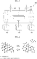
- FIG. 1 is a perspective view schematically showing the configuration of a hydrogen release and storage system 100 according to one embodiment of the present invention.
- the hydrogen release and storage system 100 includes a hydrogen compound member 101, a container (reaction container) 102 that accommodates the hydrogen compound member 101, a heating apparatus 103 configured to heat the inside of the container 102, a cooling apparatus 104 configured to cool the inside of the container 102 and a water supply apparatus 105 configured to supply water to the container 102.
- the stoichiometric ratio between an element X other than a hydrogen element that configures the hydrogen compound member 101 and the hydrogen element H is 1:1 to 3:4 (for example, XH, XH 2 , XH 3 , XH 4 , X 2 H 3 or X 3 H 4 ).
- an element other than hydrogen include boron B.
- a hydrogen release portion 106 that releases hydrogen generated from the hydrogen compound member 101 to the outside of the container 102 and an oxygen release portion 107 that releases oxygen that is generated from supplied water to the outside are provided apart from each other.
- the heating apparatus 103 may be in direct contact with or may not be in contact with the hydrogen compound member 101 to be heated.
- a heating apparatus that is attached to the outside of the container 102 is exemplified.
- As the heating apparatus 103 a combustor, an electric heater, a steam heating apparatus and the like are exemplary examples.
- the cooling apparatus 104 may be attached to the outside of the container 102 or accommodated in the container 102 as long as the hydrogen compound member 101 in the container 102 can be cooled.
- As the cooling apparatus 104 an air cooler, a water cooler and other refrigerant-type cooling apparatuses are exemplary examples.
- the inside of the container 102 may be opened and left to stand in the atmosphere without using the cooling apparatus 104.
- the water supply apparatus 105 supplies a fluid containing liquid or gaseous water as a main component to the inside of the container 102.
- the water supply apparatus 105 is capable of functioning as the cooling apparatus 104 as well.
- the hydrogen release and storage system 100 may further include a switching apparatus (not shown) that switches between a first state where the heating apparatus 103 is driven and the cooling apparatus 104 and the water supply apparatus 105 are stopped (hydrogen release state) and a second state where the heating apparatus 103 is stopped and the cooling apparatus 104 and the water supply apparatus 105 are driven (hydrogen storage state).
- a switching apparatus (not shown) that switches between a first state where the heating apparatus 103 is driven and the cooling apparatus 104 and the water supply apparatus 105 are stopped (hydrogen release state) and a second state where the heating apparatus 103 is stopped and the cooling apparatus 104 and the water supply apparatus 105 are driven (hydrogen storage state).
- FIG. 2 is a view schematically showing the configurations of the hydrogen compound member 101 in a hydrogen absorption state (left-hand side) where hydrogen elements bond to almost all bonding sites of an X element that configures a hydrogen compound and in the hydrogen release state where no hydrogen elements bond to some of the bonding sites of the X element due to hydrogen release.
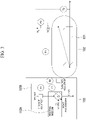
- FIG. 3 is a view schematically showing the configuration of a facility that is used in a hydrogen release step.
- the heating apparatus 103 is composed of means for supplying a heating medium (heating medium supply means) 103A and means for adjusting the temperature of the heating medium (temperature adjustment means) 103B.
- the cooling apparatus 104 and the water supply apparatus 105 that are not used in this step are not shown.
- FIG. 4 is a graph showing the relationship between the temperature of the hydrogen compound member 101 and the amount of hydrogen that is generated from the hydrogen compound member 101 (the amount of hydrogen generated).
- the hydrogen compound member 101 is made to generate hydrogen at a temperature of 150°C or higher. Therefore, first, the hydrogen compound member 101 in the hydrogen storage state shown in the left-hand side of FIG. 2 is disposed in the container 102, subsequently, the inside of the container 102 is heated using the heating apparatus 103 so as to reach 150°C or higher (preferably 150°C or higher and 300°C or lower), and the hydrogen compound member 101 is made to release hydrogen.
- the inside of the container 102 is heated by supplying the heating medium into the container 102.
- the temperature of the heating medium is adjusted using the temperature adjustment means 103B in order to prevent the temperature from excessively rising. This makes the hydrogen compound member 101 lose some hydrogen and fall into the hydrogen release state shown in the right-hand side of FIG. 2 .
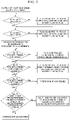
- FIG. 5 shows the flow of a more detailed process that is included in an actual hydrogen release step.
- the supply of the heating medium is begun, and the temperature T1 of the inside of the container 102 on a side where the heating medium is disposed is controlled so as to become a temperature of 300°C or lower. If the temperature exceeds 300°C, the temperature T1 is controlled so as to become 300°C or lower by changing the flow rate of water Q1.
- the temperature T2 of the container 102 on a side where the heating medium is not disposed is controlled so as to become a temperature of 250°C or lower. If the temperature exceeds 250°C, the temperature T2 is controlled so as to become 250°C or lower by changing the heating medium amount of Q2.
- the pressure P1 in the container 102 is measured, and whether or not hydrogen is generated depending on an increase in pressure is confirmed. Whether or not the pressure P2 of hydrogen H 2 that is released from the container 102 is a predetermined pressure or higher is determined. In a case where the pressure P2 is lower than the predetermined pressure, the pressure P2 is controlled so as to reach the predetermined pressure by operating a valve V2.
- the pressure P1 in the container 102 is a predetermined pressure or higher is determined.
- the pressure P1 is controlled so as to reach the predetermined pressure by changing the flow rate of water Q1.
- whether or not the pressure P1 in the container 102 is the predetermined pressure or higher is determined. In a case where the pressure P1 is lower than the predetermined pressure, the same determination is repeated by continuing the operation.
- Q2, T1 and T2 are the predetermined values or higher and P1 is the predetermined pressure or lower, that is, a state where the release of H 2 is stopped has been formed in spite of the supply of heat is determined.
- Q2, T1 and T2 are adjusted so as to reach the predetermined values or higher by changing the water flow rate Q1.
- the release of hydrogen is ended.
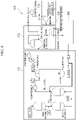
- FIG. 6 is a view schematically showing the configuration of a facility that is used in a hydrogen storage step.
- the cooling apparatus 104 is composed of means for supplying a cooling water (cooling water supply means) 104A and means for adjusting the temperature of the cooling water (temperature adjustment means) 104B.
- the water supply apparatus 105 is composed of means for supplying a raw material water (raw material water supply means) 105A and means for adjusting the flow rate of the raw material water to be supplied (flow rate adjustment means) 105B.
- the heating apparatus 103 that is not used in this step is not shown.
- water is supplied into the container 102 while cooling the inside of the container 102 so as to reach lower than 150°C (preferably 80°C or higher and 150°C or lower) using the cooling apparatus 104, and hydrogen is absorbed into the hydrogen compound member 101.
- Hydrogen thermally decomposed from the water due to the temperature in the container 102 bond to a non-bonding site of the hydrogen compound member 101, whereby the hydrogen compound member 101 returns to the hydrogen storage state shown on the left-hand side of FIG. 2 .
- FIG. 7 shows the flow of a more detailed process that is included in an actual hydrogen storage step.
- the supply of the cooling water is begun, and the temperature T3 of the inside of the container 102 on a side where the cooling water is disposed is controlled so as to become a temperature of 80°C or lower. If the temperature exceeds 80°C, the temperature T1 is controlled so as to become 80°C or lower by changing the water flow rate Q3.
- the temperature T4 of the container 102 on a side where the cooling water is not disposed is controlled so as to become a temperature of 75°C or lower. If the temperature exceeds 75°C, the temperature T1 is controlled so as to become 75°C or lower by changing the water flow rate Q4.
- hydrogen in the container 102 is removed by initiating VP.
- the operation of VP is continued until the pressure P1 reaches a predetermined pressure or lower, thereby removing hydrogen in the container 102.
- the operation of VP is stopped, and the supply of the raw material water is begun by opening V6.
- the temperature of the raw material water is adjusted so as to be in a predetermined temperature range by changing the water flow rate Q5.
- the hydrogen release and storage system 100 of the present embodiment can be used as a hydrogen supply source in a variety of apparatuses in which hydrogen is used as a raw material. Furthermore, since hydrogen can be generated without newly adding energy by using exhaust heat that is generated in the apparatuses to heat the hydrogen compound member 101 to generate hydrogen, it is possible to reduce the amount of natural gas used in association with the addition of energy.
- FIG. 8 is a view schematically showing the configuration of an ammonia production apparatus 110 to which the hydrogen release and storage system 100 is applied.
- the ammonia production apparatus 110 is mainly composed of a raw material preparation portion 111, an ammonia synthesis portion 112 and an ammonia collection portion 113.
- the heating apparatus and the cooling apparatus that configure the hydrogen release and storage system 100 can be made to function as a temperature adjustment apparatus 114 that adjusts the temperature of generated ammonia.
- exhaust heat having a medium temperature of approximately 400°C that is generated in association with ammonia synthesis makes it possible to heat the hydrogen compound member 101 with no additional energy and to generate hydrogen.
- the generated hydrogen is supplied at a predetermined timing of raw material preparation, it becomes possible to synthesize additional ammonia using this hydrogen as a raw material. This makes it possible to reduce the amount of a methane raw material that is injected as a raw material for ammonia synthesis.
- FIG. 9 is a view schematically showing the configuration of a gas turbine 120 to which the hydrogen release and storage system 100 is applied.
- the use of exhaust heat of approximately 300°C that is generated in the gas turbine 120 makes it possible to heat the hydrogen compound member 101 with no additional energy and to generate hydrogen.
- the generated hydrogen is supplied to a combustor 120A that configures the gas turbine 120, additional gas turbine combustion becomes possible using this hydrogen as a fuel. This makes it possible to reduce the amount of natural gas that is injected as a fuel for gas turbine combustion.
- FIG. 10 is a view schematically showing the configuration of a solid oxide fuel cell (SOFC) 130 to which the hydrogen release and storage system 100 is applied.
- SOFC solid oxide fuel cell
- the use of exhaust heat of approximately 600°C to 1200°C that is generated in the production process of the fuel cell 130 makes it possible to heat the hydrogen compound member 101 with no additional energy and to generate hydrogen.
- the hydrogen can be used as a fuel of the fuel cell. This makes it possible to reduce the amount of natural gas that is injected as a fuel of the fuel cell.
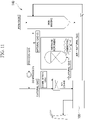
- FIG. 11 is a view schematically showing the configuration of a steel mill 140 to which the hydrogen release and storage system 100 is applied.
- the use of exhaust heat that is generated in an iron-making step makes it possible to heat the hydrogen compound member 101 with no additional energy and to generate hydrogen.
- the generated hydrogen can be used as a raw material for iron reduction for iron making (Fe 2 O 3 + 3H 2 ⁇ 2Fe + 3H 2 O). This makes it possible to reduce the amount of natural gas that is injected as a raw material for iron reduction.
Landscapes
- Chemical & Material Sciences (AREA)
- Engineering & Computer Science (AREA)
- Chemical Kinetics & Catalysis (AREA)
- Manufacturing & Machinery (AREA)
- Life Sciences & Earth Sciences (AREA)
- Organic Chemistry (AREA)
- General Chemical & Material Sciences (AREA)
- Electrochemistry (AREA)
- Sustainable Energy (AREA)
- Sustainable Development (AREA)
- Inorganic Chemistry (AREA)
- Combustion & Propulsion (AREA)
- Analytical Chemistry (AREA)
- Metallurgy (AREA)
- Materials Engineering (AREA)
- Health & Medical Sciences (AREA)
- General Health & Medical Sciences (AREA)
- General Engineering & Computer Science (AREA)
- Mechanical Engineering (AREA)
- Geology (AREA)
- General Life Sciences & Earth Sciences (AREA)
- Environmental & Geological Engineering (AREA)
- Fuel Cell (AREA)
- Hydrogen, Water And Hydrids (AREA)
- Manufacture Of Iron (AREA)
- Blast Furnaces (AREA)
- Solid-Sorbent Or Filter-Aiding Compositions (AREA)
Abstract
Description
- The present invention relates to a hydrogen release and storage system, a hydrogen release and storage method, an ammonia production apparatus, a gas turbine, a fuel cell and a steel mill.
- Priority is claimed on
Japanese Patent Application No. 2020-071758, filed in Japan on April 13, 2020 - Hydrogen energy is in use in a variety of processes such as ammonia synthesis, gas combustion, the manufacture of solid oxide fuel cells and iron making. It is known that huge effort and cost are required to supply a hydrogen gas, which serves as a raw material, and there is a demand for a technique that improves the current situation. In addition, in processes where hydrogen energy is used, a large amount of exhaust heat is generated, and thus there is a demand for a method for effectively using hydrogen energy.
- [Patent Document 1]
PTC International Publication No.WO 2018/074518 - As a material that generates hydrogen, borohydrides are being studied.
Patent Document 1 discloses a sheet containing a borohydride in a two-dimensional manner (Patent Document 1). However, when all of the hydrogen that is contained in the sheet has been generated, there is a need to supply a new sheet, and additional effort and cost as much are required. - The present invention has been made in consideration of the above-described circumstances, and an objective of the present invention is to provide a hydrogen release and storage system, a hydrogen release and storage method, an ammonia production apparatus, a gas turbine, a fuel cell and a steel mill which enable the effective use of exhaust heat and suppression of the generation of additional energy necessary for hydrogen generation.
- In order to solve the above-described problem, the present invention adopts the following means.
- (1) A hydrogen release and storage system according to one aspect of the present invention includes a hydrogen compound member, a container that accommodates the hydrogen compound member, a heating apparatus configured to heat an inside of the container, a cooling apparatus configured to cool the inside of the container and a water supply apparatus configured to supply water to the inside of the container.
- (2) In the hydrogen release and storage system according to (1), a stoichiometric ratio between an element other than a hydrogen element that configures the hydrogen compound member and the hydrogen element is preferably 1:1 to 3:4.
- (3) In the hydrogen release and storage system according to (2), an element other than hydrogen may be boron.
- (4) The hydrogen release and storage system according to any one of (1) to (3) may further include a switching apparatus that switches between a first state and a second state, the first state is a state where the heating apparatus is driven and the cooling apparatus and the water supply apparatus are stopped and a second state is a state where the heating apparatus is stopped and the cooling apparatus and the water supply apparatus are driven.
- (5) A hydrogen release and storage method according to one aspect of the present invention is a hydrogen release and storage method in which the hydrogen release and storage system according to any one of (1) to (4) is used as a hydrogen supply source and alternately has a hydrogen release step of heating the inside of the container so as to reach 150°C or higher and releasing hydrogen from the hydrogen compound member and a hydrogen absorption step of supplying water to the inside of the container while cooling the inside of the container so as to reach lower than 150°C and absorbing the hydrogen into the hydrogen compound member.
- (6) An ammonia production apparatus according to one aspect of the present invention includes the hydrogen release and storage system according to any one of (1) to (4) as a hydrogen supply source.
- (7) A gas turbine according to one aspect of the present invention includes the hydrogen release and storage system according to any one of (1) to (4) as a hydrogen supply source.
- (8) A fuel cell according to one aspect of the present invention includes the hydrogen release and storage system according to any one of (1) to (4) as a hydrogen supply source.
- (9) A steel mill according to one aspect of the present invention includes the hydrogen release and storage system according to any one of (1) to (4) as a hydrogen supply source.
- The hydrogen release and storage system of the present invention can be used as a hydrogen supply source in a variety of apparatuses in which hydrogen is used as a raw material. Furthermore, since hydrogen can be generated without newly adding energy by using exhaust heat that is generated in the apparatuses to heat the hydrogen compound member to generate hydrogen, it is possible to reduce the amount of natural gas used in association with the addition of energy.
-
-
FIG. 1 is a view schematically showing the configuration of a hydrogen release and storage system according to one embodiment of the present invention. -
FIG. 2 is a view schematically showing the configurations of a hydrogen compound member in a hydrogen absorption state and in a hydrogen release state. -
FIG. 3 is a view schematically showing the configuration of a facility that is used in a hydrogen release step in a hydrogen release and storage method according to one embodiment of the present invention. -
FIG. 4 is a graph showing the relationship between the temperature of the hydrogen compound member and the amount of hydrogen that is generated from the hydrogen compound member. -
FIG. 5 is the flow of a process that is included in the hydrogen release step. -
FIG. 6 is a view schematically showing the configuration of a facility that is used in a hydrogen storage step in a hydrogen release and storage method according to one embodiment of the present invention. -
FIG. 7 is the flow of a process that is included in the hydrogen storage step. -
FIG. 8 is a view schematically showing the configuration of an ammonia production apparatus to which the hydrogen release and storage system is applied. -
FIG. 9 is a view schematically showing the configuration of a gas turbine to which the hydrogen release and storage system is applied. -
FIG. 10 is a view schematically showing the configuration of a fuel cell to which the hydrogen release and storage system is applied. -
FIG. 11 is a view schematically showing the configuration of a steel mill to which the hydrogen release and storage system is applied. - Hereinafter, a hydrogen release and storage system according to an embodiment to which the present invention is applied will be described in detail using drawings. In some of the drawings to be used in the following description, a characteristic portion is shown in an enlarged manner for convenience in order to facilitate the understanding of the characteristic, and the dimensional ratios and the like of each configurational element are not always the same as those in actual cases. In addition, materials, dimensions, and the like to be exemplified in the following description are simply examples, and the present invention is not limited thereto and can be appropriately modified and carried out within the scope of the gist of the present invention.
-
FIG. 1 is a perspective view schematically showing the configuration of a hydrogen release andstorage system 100 according to one embodiment of the present invention. The hydrogen release andstorage system 100 includes ahydrogen compound member 101, a container (reaction container) 102 that accommodates thehydrogen compound member 101, aheating apparatus 103 configured to heat the inside of thecontainer 102, acooling apparatus 104 configured to cool the inside of thecontainer 102 and awater supply apparatus 105 configured to supply water to thecontainer 102. - The stoichiometric ratio between an element X other than a hydrogen element that configures the
hydrogen compound member 101 and the hydrogen element H is 1:1 to 3:4 (for example, XH, XH2, XH3, XH4, X2H3 or X3H4). Examples of an element other than hydrogen include boron B. - In the side wall portion of the
container 102, ahydrogen release portion 106 that releases hydrogen generated from thehydrogen compound member 101 to the outside of thecontainer 102 and anoxygen release portion 107 that releases oxygen that is generated from supplied water to the outside are provided apart from each other. - The
heating apparatus 103 may be in direct contact with or may not be in contact with thehydrogen compound member 101 to be heated. Here, a heating apparatus that is attached to the outside of thecontainer 102 is exemplified. As theheating apparatus 103, a combustor, an electric heater, a steam heating apparatus and the like are exemplary examples. - The
cooling apparatus 104 may be attached to the outside of thecontainer 102 or accommodated in thecontainer 102 as long as thehydrogen compound member 101 in thecontainer 102 can be cooled. As thecooling apparatus 104, an air cooler, a water cooler and other refrigerant-type cooling apparatuses are exemplary examples. For cooling, the inside of thecontainer 102 may be opened and left to stand in the atmosphere without using thecooling apparatus 104. - The
water supply apparatus 105 supplies a fluid containing liquid or gaseous water as a main component to the inside of thecontainer 102. When the temperature of the fluid becomes close to the intended cooling temperature, since it is possible to make the water to be supplied function as a refrigerant, thewater supply apparatus 105 is capable of functioning as thecooling apparatus 104 as well. - The hydrogen release and
storage system 100 may further include a switching apparatus (not shown) that switches between a first state where theheating apparatus 103 is driven and thecooling apparatus 104 and thewater supply apparatus 105 are stopped (hydrogen release state) and a second state where theheating apparatus 103 is stopped and thecooling apparatus 104 and thewater supply apparatus 105 are driven (hydrogen storage state). -
FIG. 2 is a view schematically showing the configurations of thehydrogen compound member 101 in a hydrogen absorption state (left-hand side) where hydrogen elements bond to almost all bonding sites of an X element that configures a hydrogen compound and in the hydrogen release state where no hydrogen elements bond to some of the bonding sites of the X element due to hydrogen release. - When the hydrogen release and storage system of the present embodiment is used as a hydrogen supply source, it is possible to carry out a hydrogen release and storage method in the following procedure.
-
FIG. 3 is a view schematically showing the configuration of a facility that is used in a hydrogen release step. Theheating apparatus 103 is composed of means for supplying a heating medium (heating medium supply means) 103A and means for adjusting the temperature of the heating medium (temperature adjustment means) 103B. Thecooling apparatus 104 and thewater supply apparatus 105 that are not used in this step are not shown. -
FIG. 4 is a graph showing the relationship between the temperature of thehydrogen compound member 101 and the amount of hydrogen that is generated from the hydrogen compound member 101 (the amount of hydrogen generated). As shown in this graph, thehydrogen compound member 101 is made to generate hydrogen at a temperature of 150°C or higher. Therefore, first, thehydrogen compound member 101 in the hydrogen storage state shown in the left-hand side ofFIG. 2 is disposed in thecontainer 102, subsequently, the inside of thecontainer 102 is heated using theheating apparatus 103 so as to reach 150°C or higher (preferably 150°C or higher and 300°C or lower), and thehydrogen compound member 101 is made to release hydrogen. The inside of thecontainer 102 is heated by supplying the heating medium into thecontainer 102. At the same time, the temperature of the heating medium is adjusted using the temperature adjustment means 103B in order to prevent the temperature from excessively rising. This makes thehydrogen compound member 101 lose some hydrogen and fall into the hydrogen release state shown in the right-hand side ofFIG. 2 . -
FIG. 5 shows the flow of a more detailed process that is included in an actual hydrogen release step. First, the supply of the heating medium is begun, and the temperature T1 of the inside of thecontainer 102 on a side where the heating medium is disposed is controlled so as to become a temperature of 300°C or lower. If the temperature exceeds 300°C, the temperature T1 is controlled so as to become 300°C or lower by changing the flow rate of water Q1. - Next, the temperature T2 of the
container 102 on a side where the heating medium is not disposed is controlled so as to become a temperature of 250°C or lower. If the temperature exceeds 250°C, the temperature T2 is controlled so as to become 250°C or lower by changing the heating medium amount of Q2. - Next, the pressure P1 in the
container 102 is measured, and whether or not hydrogen is generated depending on an increase in pressure is confirmed. Whether or not the pressure P2 of hydrogen H2 that is released from thecontainer 102 is a predetermined pressure or higher is determined. In a case where the pressure P2 is lower than the predetermined pressure, the pressure P2 is controlled so as to reach the predetermined pressure by operating a valve V2. - Next, whether or not the pressure P1 in the
container 102 is a predetermined pressure or higher is determined. In a case where the pressure P1 is lower than the predetermined pressure, the pressure P1 is controlled so as to reach the predetermined pressure by changing the flow rate of water Q1. Subsequently, whether or not the pressure P1 in thecontainer 102 is the predetermined pressure or higher is determined. In a case where the pressure P1 is lower than the predetermined pressure, the same determination is repeated by continuing the operation. - Next, whether or not Q2, T1 and T2 are the predetermined values or higher and P1 is the predetermined pressure or lower, that is, a state where the release of H2 is stopped has been formed in spite of the supply of heat is determined. In a case where these fail to satisfy the predetermined values, Q2, T1 and T2 are adjusted so as to reach the predetermined values or higher by changing the water flow rate Q1. In a case where these satisfy the predetermined values, the release of hydrogen is ended.
-
FIG. 6 is a view schematically showing the configuration of a facility that is used in a hydrogen storage step. Thecooling apparatus 104 is composed of means for supplying a cooling water (cooling water supply means) 104A and means for adjusting the temperature of the cooling water (temperature adjustment means) 104B. In addition, thewater supply apparatus 105 is composed of means for supplying a raw material water (raw material water supply means) 105A and means for adjusting the flow rate of the raw material water to be supplied (flow rate adjustment means) 105B. Theheating apparatus 103 that is not used in this step is not shown. - Next, water is supplied into the
container 102 while cooling the inside of thecontainer 102 so as to reach lower than 150°C (preferably 80°C or higher and 150°C or lower) using thecooling apparatus 104, and hydrogen is absorbed into thehydrogen compound member 101. Hydrogen thermally decomposed from the water due to the temperature in thecontainer 102 bond to a non-bonding site of thehydrogen compound member 101, whereby thehydrogen compound member 101 returns to the hydrogen storage state shown on the left-hand side ofFIG. 2 . - When the hydrogen release step and the hydrogen absorption step are carried out alternately, it is possible to continuously supply hydrogen to predetermined facilities.
-
FIG. 7 shows the flow of a more detailed process that is included in an actual hydrogen storage step. First, the supply of the cooling water is begun, and the temperature T3 of the inside of thecontainer 102 on a side where the cooling water is disposed is controlled so as to become a temperature of 80°C or lower. If the temperature exceeds 80°C, the temperature T1 is controlled so as to become 80°C or lower by changing the water flow rate Q3. - Next, the temperature T4 of the
container 102 on a side where the cooling water is not disposed is controlled so as to become a temperature of 75°C or lower. If the temperature exceeds 75°C, the temperature T1 is controlled so as to become 75°C or lower by changing the water flow rate Q4. - Next, hydrogen in the
container 102 is removed by initiating VP. The operation of VP is continued until the pressure P1 reaches a predetermined pressure or lower, thereby removing hydrogen in thecontainer 102. - Next, the operation of VP is stopped, and the supply of the raw material water is begun by opening V6. Next, the temperature of the raw material water is adjusted so as to be in a predetermined temperature range by changing the water flow rate Q5.
- Next, whether or not the pressure P1 in the container is the predetermined pressure or higher is determined, and, in a case where the pressure P1 is lower than the predetermined pressure, the operation is continued until the pressure P1 reaches the predetermined pressure or higher. When the pressure P1 is the predetermined pressure or higher, the production of hydrogen is ended.
- As described above, the hydrogen release and
storage system 100 of the present embodiment can be used as a hydrogen supply source in a variety of apparatuses in which hydrogen is used as a raw material. Furthermore, since hydrogen can be generated without newly adding energy by using exhaust heat that is generated in the apparatuses to heat thehydrogen compound member 101 to generate hydrogen, it is possible to reduce the amount of natural gas used in association with the addition of energy. - Hereinafter, application examples of the hydrogen release and
storage system 100 of the present embodiment will be listed. -
FIG. 8 is a view schematically showing the configuration of anammonia production apparatus 110 to which the hydrogen release andstorage system 100 is applied. Theammonia production apparatus 110 is mainly composed of a rawmaterial preparation portion 111, anammonia synthesis portion 112 and anammonia collection portion 113. The heating apparatus and the cooling apparatus that configure the hydrogen release andstorage system 100 can be made to function as atemperature adjustment apparatus 114 that adjusts the temperature of generated ammonia. - The use of exhaust heat having a medium temperature of approximately 400°C that is generated in association with ammonia synthesis makes it possible to heat the
hydrogen compound member 101 with no additional energy and to generate hydrogen. When the generated hydrogen is supplied at a predetermined timing of raw material preparation, it becomes possible to synthesize additional ammonia using this hydrogen as a raw material. This makes it possible to reduce the amount of a methane raw material that is injected as a raw material for ammonia synthesis. -
FIG. 9 is a view schematically showing the configuration of agas turbine 120 to which the hydrogen release andstorage system 100 is applied. The use of exhaust heat of approximately 300°C that is generated in thegas turbine 120 makes it possible to heat thehydrogen compound member 101 with no additional energy and to generate hydrogen. When the generated hydrogen is supplied to acombustor 120A that configures thegas turbine 120, additional gas turbine combustion becomes possible using this hydrogen as a fuel. This makes it possible to reduce the amount of natural gas that is injected as a fuel for gas turbine combustion. -
FIG. 10 is a view schematically showing the configuration of a solid oxide fuel cell (SOFC) 130 to which the hydrogen release andstorage system 100 is applied. The use of exhaust heat of approximately 600°C to 1200°C that is generated in the production process of thefuel cell 130 makes it possible to heat thehydrogen compound member 101 with no additional energy and to generate hydrogen. When the generated hydrogen is supplied to thefuel cell 130, the hydrogen can be used as a fuel of the fuel cell. This makes it possible to reduce the amount of natural gas that is injected as a fuel of the fuel cell. -
FIG. 11 is a view schematically showing the configuration of asteel mill 140 to which the hydrogen release andstorage system 100 is applied. The use of exhaust heat that is generated in an iron-making step makes it possible to heat thehydrogen compound member 101 with no additional energy and to generate hydrogen. The generated hydrogen can be used as a raw material for iron reduction for iron making (Fe2O3 + 3H2 → 2Fe + 3H2O). This makes it possible to reduce the amount of natural gas that is injected as a raw material for iron reduction. -
- 100 Hydrogen release and storage system
- 101 Hydrogen compound member
- 102 Container
- 103 Heating apparatus
- 103A Heating medium supply means
- 103B Temperature adjustment means
- 104 Cooling apparatus
- 104A Cooling water supply means
- 104B Temperature adjustment means
- 105 Water supply apparatus
- 105A Raw material water supply means
- 105B Flow rate adjustment means
- 106 Hydrogen release portion
- 107 Oxygen release portion
- 110 Ammonia production apparatus
- 111 Raw material preparation portion
- 112 Ammonia synthesis portion
- 113 Ammonia collection portion
- 114 Temperature adjustment apparatus
- 120 Gas turbine
- 120A Combustor
- 130 Fuel cell
- 140 Steel mill
Claims (9)
- A hydrogen release and storage system comprising:a hydrogen compound member;a container that accommodates the hydrogen compound member;a heating apparatus configured to heat an inside of the container;a cooling apparatus configured to cool the inside of the container; anda water supply apparatus configured to supply water to the inside of the container.
- The hydrogen release and storage system according to Claim 1,
wherein a stoichiometric ratio between an element other than a hydrogen element that configures the hydrogen compound member and the hydrogen element is 1:1 to 3:4. - The hydrogen release and storage system according to Claim 2,
wherein an element other than the hydrogen element is boron. - The hydrogen release and storage system according to any one of Claims 1 to 3, further comprising:a switching apparatus that switches between a first state and a second state,the first state is a state where the heating apparatus is driven and the cooling apparatus and the water supply apparatus are stopped anda second state is a state where the heating apparatus is stopped and the cooling apparatus and the water supply apparatus are driven.
- A hydrogen release and storage method in which the hydrogen release and storage system according to any one of Claims 1 to 4 is used as a hydrogen supply source, the method alternately comprising:a hydrogen release step of heating the inside of the container so as to reach 150°C or higher and releasing hydrogen from the hydrogen compound member, anda hydrogen absorption step of supplying water to the inside of the container while cooling the inside of the container so as to reach lower than 150°C and absorbing the hydrogen into the hydrogen compound member.
- An ammonia production apparatus comprising:
the hydrogen release and storage system according to any one of Claims 1 to 4 as a hydrogen supply source. - A gas turbine comprising:
the hydrogen release and storage system according to any one of Claims 1 to 4 as a hydrogen supply source. - A fuel cell comprising:
the hydrogen release and storage system according to any one of Claims 1 to 4 as a hydrogen supply source. - A steel mill comprising:
the hydrogen release and storage system according to any one of Claims 1 to 4 as a hydrogen supply source.
Applications Claiming Priority (2)
| Application Number | Priority Date | Filing Date | Title |
|---|---|---|---|
| JP2020071758A JP7354050B2 (en) | 2020-04-13 | 2020-04-13 | Hydrogen release/storage system, hydrogen release/storage method, hydrogen release/storage device, ammonia production device, gas turbine, fuel cell, and steelworks |
| PCT/JP2021/011681 WO2021210351A1 (en) | 2020-04-13 | 2021-03-22 | Hydrogen release and storage system, hydrogen release and storage method, ammonia production apparatus, gas turbine, fuel cell, and ironworks factory |
Publications (2)
| Publication Number | Publication Date |
|---|---|
| EP4119494A1 true EP4119494A1 (en) | 2023-01-18 |
| EP4119494A4 EP4119494A4 (en) | 2023-11-29 |
Family
ID=78079309
Family Applications (1)
| Application Number | Title | Priority Date | Filing Date |
|---|---|---|---|
| EP21788349.5A Pending EP4119494A4 (en) | 2020-04-13 | 2021-03-22 | HYDROGEN STORAGE AND RELEASE SYSTEM, HYDROGEN STORAGE AND RELEASE METHOD, AMMONIA PRODUCTION APPARATUS, GAS TURBINE, FUEL CELL AND STEEL PLANT |
Country Status (6)
| Country | Link |
|---|---|
| US (1) | US12503362B2 (en) |
| EP (1) | EP4119494A4 (en) |
| JP (1) | JP7354050B2 (en) |
| CN (1) | CN115443249B (en) |
| AU (1) | AU2021255266B9 (en) |
| WO (1) | WO2021210351A1 (en) |
Cited By (1)
| Publication number | Priority date | Publication date | Assignee | Title |
|---|---|---|---|---|
| US12595170B2 (en) | 2022-03-28 | 2026-04-07 | Mitsubishi Heavy Industries, Ltd. | Hydrogen production system |
Families Citing this family (2)
| Publication number | Priority date | Publication date | Assignee | Title |
|---|---|---|---|---|
| JP7386211B2 (en) * | 2021-08-24 | 2023-11-24 | 三菱重工業株式会社 | Hydrogen production system |
| JP2024042427A (en) * | 2022-09-15 | 2024-03-28 | 国立大学法人東京工業大学 | Composition containing borohydride sheet and carrier, and method for releasing hydrogen using the same |
Family Cites Families (24)
| Publication number | Priority date | Publication date | Assignee | Title |
|---|---|---|---|---|
| JPH05225996A (en) | 1992-02-12 | 1993-09-03 | Toshiba Corp | Fuel cell power generation system |
| JP4843845B2 (en) | 2000-07-03 | 2011-12-21 | トヨタ自動車株式会社 | Fuel cell system and control method thereof |
| JP2005063715A (en) * | 2003-08-08 | 2005-03-10 | Japan Steel Works Ltd:The | Hydrogen storage and supply device for fuel cells |
| US20050132640A1 (en) * | 2003-12-19 | 2005-06-23 | Kelly Michael T. | Fuel blends for hydrogen generators |
| JP2005200245A (en) * | 2004-01-14 | 2005-07-28 | Honda Motor Co Ltd | Nitrogen production apparatus, ammonia synthesis system, nitrogen production method, and ammonia synthesis method |
| US20060269470A1 (en) | 2004-04-14 | 2006-11-30 | Qinglin Zhang | Methods and devices for hydrogen generation from solid hydrides |
| JP2005298302A (en) | 2004-04-15 | 2005-10-27 | Seiko Epson Corp | Hydrogen cartridge and equipment |
| JP2005314151A (en) * | 2004-04-28 | 2005-11-10 | Honda Motor Co Ltd | Ammonia synthesis apparatus and ammonia synthesis method |
| US20060029529A1 (en) * | 2004-08-03 | 2006-02-09 | Pinkerton Frederick E | Pressurized hydrogen delivery system for electrochemical cells |
| JP4781655B2 (en) | 2004-10-28 | 2011-09-28 | 出光興産株式会社 | Fuel cell system and control method of fuel cell system |
| JP4704733B2 (en) * | 2004-10-28 | 2011-06-22 | 出光興産株式会社 | Fuel cell system |
| JP2010017700A (en) * | 2008-07-14 | 2010-01-28 | Techno Bank:Kk | Method for using waste material of lightweight structural material |
| CN101880046A (en) | 2009-05-05 | 2010-11-10 | 中村德彦 | Compound equipment |
| AU2010272097B2 (en) | 2009-07-13 | 2013-05-09 | Kawasaki Jukogyo Kabushiki Kaisha | Hydrogen Production Method and Hydrogen Production System |
| JP5764832B2 (en) | 2011-03-16 | 2015-08-19 | 水素燃料開発株式会社 | Hydrogen gas generation method and apparatus |
| JP2016185899A (en) | 2015-03-27 | 2016-10-27 | 国立大学法人 筑波大学 | Two-dimensional boron-containing sheet and manufacturing method thereof |
| KR20170097386A (en) * | 2016-02-18 | 2017-08-28 | 현대자동차주식회사 | Solid state hydrogen storage divice |
| WO2018074518A1 (en) | 2016-10-18 | 2018-04-26 | 国立大学法人筑波大学 | Sheet containing two-dimensional borohydride and production method for sheet containing two-dimensional boron compound |
| JP7017236B2 (en) | 2017-04-26 | 2022-02-08 | 国立大学法人 琉球大学 | Hydrogen generation method |
| JP6805456B2 (en) | 2017-12-01 | 2020-12-23 | 公立大学法人兵庫県立大学 | Hydrogen production catalyst and its production method, and hydrogen production method |
| JP7079932B2 (en) | 2018-06-22 | 2022-06-03 | 国立大学法人東京工業大学 | Hydrogen generation method, hydrogen generation system and fuel cell system |
| JP2020071758A (en) | 2018-11-01 | 2020-05-07 | 株式会社Nttドコモ | Control system and control method |
| CN110106512A (en) | 2019-04-17 | 2019-08-09 | 河北工业大学 | Device for preparing hydrogen |
| JP7485287B2 (en) * | 2020-10-05 | 2024-05-16 | 株式会社デンソー | Hydrogen Generator |
-
2020
- 2020-04-13 JP JP2020071758A patent/JP7354050B2/en active Active
-
2021
- 2021-03-22 US US17/917,867 patent/US12503362B2/en active Active
- 2021-03-22 EP EP21788349.5A patent/EP4119494A4/en active Pending
- 2021-03-22 WO PCT/JP2021/011681 patent/WO2021210351A1/en not_active Ceased
- 2021-03-22 CN CN202180027902.2A patent/CN115443249B/en active Active
- 2021-03-22 AU AU2021255266A patent/AU2021255266B9/en active Active
Cited By (1)
| Publication number | Priority date | Publication date | Assignee | Title |
|---|---|---|---|---|
| US12595170B2 (en) | 2022-03-28 | 2026-04-07 | Mitsubishi Heavy Industries, Ltd. | Hydrogen production system |
Also Published As
| Publication number | Publication date |
|---|---|
| CN115443249B (en) | 2024-07-05 |
| EP4119494A4 (en) | 2023-11-29 |
| CN115443249A (en) | 2022-12-06 |
| WO2021210351A1 (en) | 2021-10-21 |
| US12503362B2 (en) | 2025-12-23 |
| US20230141693A1 (en) | 2023-05-11 |
| JP7354050B2 (en) | 2023-10-02 |
| AU2021255266A1 (en) | 2022-11-10 |
| AU2021255266B9 (en) | 2024-06-13 |
| JP2021167262A (en) | 2021-10-21 |
| AU2021255266B2 (en) | 2024-05-30 |
Similar Documents
| Publication | Publication Date | Title |
|---|---|---|
| US12582953B2 (en) | Hydrogen release/storage system, hydrogen release/storage method, ammonia production equipment, gas turbine, fuel cell, and steel mill | |
| US12503362B2 (en) | Hydrogen release and storage system, hydrogen release and storage method, ammonia production apparatus, gas turbine, fuel cell, and steel mill | |
| US5741474A (en) | Process for production of high-purity hydrogen | |
| US7232553B2 (en) | Plate type steam reformer | |
| JP4674746B2 (en) | Hydrogen gas generation method using activated aluminum fine particles | |
| JP2008529218A (en) | Fuel cell power plant | |
| JP2016091644A (en) | Composite power generation system, and controller, method, and program for the same | |
| KR102931334B1 (en) | Hydrogen Reforming System | |
| US11867092B2 (en) | System having a combustion power plant and an electrolysis unit, and method for operating a system of this type | |
| JP6356481B2 (en) | Fuel cell system | |
| JP2014107056A (en) | Fuel cell power generation system | |
| WO2012017961A1 (en) | Fuel cell power generation system and manufacturing method thereof | |
| CA2304752C (en) | Hydrogen catalysis power cell for energy conversion systems | |
| CN117936853B (en) | SOFC power generation system with external reforming | |
| EP4493512A1 (en) | System and method for producing hydrogen | |
| Kandepu et al. | Control-relevant modeling and simulation of a SOFC-GT hybrid system | |
| KR20250156050A (en) | Device for producing hydrogen using thermochemical redox cycel | |
| Morandi et al. | Influence of Different Hydrogen/Methane Mixtures on the Operability of Small-size Burners for Energy Production | |
| Chambon et al. | Design of a lab-scale rotary cavity-type solar reactor for continuous thermal reduction of volatile oxides under reduced pressure | |
| Ringel et al. | SOFC design with internal heat exchange and gas reforming | |
| JPH07122285A (en) | Method and device for cooling transformer for fuel cell power generator | |
| JPH0432163A (en) | Method and device for improving load followability of molten carbonate fuel cell power generation system | |
| JPH0360402A (en) | Fuel cell power generating plant | |
| Maekawa et al. | Development of a portable hydrogen generator system | |
| JPH11126625A (en) | Battery differential pressure controller for fuel cell power generator |
Legal Events
| Date | Code | Title | Description |
|---|---|---|---|
| STAA | Information on the status of an ep patent application or granted ep patent |
Free format text: STATUS: THE INTERNATIONAL PUBLICATION HAS BEEN MADE |
|
| PUAI | Public reference made under article 153(3) epc to a published international application that has entered the european phase |
Free format text: ORIGINAL CODE: 0009012 |
|
| STAA | Information on the status of an ep patent application or granted ep patent |
Free format text: STATUS: REQUEST FOR EXAMINATION WAS MADE |
|
| 17P | Request for examination filed |
Effective date: 20221010 |
|
| AK | Designated contracting states |
Kind code of ref document: A1 Designated state(s): AL AT BE BG CH CY CZ DE DK EE ES FI FR GB GR HR HU IE IS IT LI LT LU LV MC MK MT NL NO PL PT RO RS SE SI SK SM TR |
|
| DAV | Request for validation of the european patent (deleted) | ||
| DAX | Request for extension of the european patent (deleted) | ||
| A4 | Supplementary search report drawn up and despatched |
Effective date: 20231030 |
|
| RIC1 | Information provided on ipc code assigned before grant |
Ipc: H01M 8/12 20160101ALI20231024BHEP Ipc: H01M 8/0606 20160101ALI20231024BHEP Ipc: H01M 8/06 20160101ALI20231024BHEP Ipc: H01M 8/04 20160101ALI20231024BHEP Ipc: F02C 3/30 20060101ALI20231024BHEP Ipc: C21B 13/00 20060101ALI20231024BHEP Ipc: C21B 7/00 20060101ALI20231024BHEP Ipc: C21B 5/00 20060101ALI20231024BHEP Ipc: C01B 6/00 20060101ALI20231024BHEP Ipc: C01C 1/04 20060101ALI20231024BHEP Ipc: C01B 3/00 20060101ALI20231024BHEP Ipc: C01B 3/04 20060101AFI20231024BHEP |