EP4119475B1 - System for replacing a reel of material for the production of electrical energy storage devices and related method - Google Patents
System for replacing a reel of material for the production of electrical energy storage devices and related method Download PDFInfo
- Publication number
- EP4119475B1 EP4119475B1 EP22183383.3A EP22183383A EP4119475B1 EP 4119475 B1 EP4119475 B1 EP 4119475B1 EP 22183383 A EP22183383 A EP 22183383A EP 4119475 B1 EP4119475 B1 EP 4119475B1
- Authority
- EP
- European Patent Office
- Prior art keywords
- reel
- spindle
- initial flap
- feeding unit
- flap
- Prior art date
- Legal status (The legal status is an assumption and is not a legal conclusion. Google has not performed a legal analysis and makes no representation as to the accuracy of the status listed.)
- Active
Links
Images


Classifications
-
- B—PERFORMING OPERATIONS; TRANSPORTING
- B65—CONVEYING; PACKING; STORING; HANDLING THIN OR FILAMENTARY MATERIAL
- B65H—HANDLING THIN OR FILAMENTARY MATERIAL, e.g. SHEETS, WEBS, CABLES
- B65H19/00—Changing the web roll
- B65H19/10—Changing the web roll in unwinding mechanisms or in connection with unwinding operations
- B65H19/12—Lifting, transporting, or inserting the web roll; Removing empty core
- B65H19/123—Lifting, transporting, or inserting the web roll; Removing empty core with cantilever supporting arrangements
-
- B—PERFORMING OPERATIONS; TRANSPORTING
- B65—CONVEYING; PACKING; STORING; HANDLING THIN OR FILAMENTARY MATERIAL
- B65H—HANDLING THIN OR FILAMENTARY MATERIAL, e.g. SHEETS, WEBS, CABLES
- B65H16/00—Unwinding, paying-out webs
- B65H16/02—Supporting web roll
- B65H16/04—Supporting web roll cantilever type
-
- B—PERFORMING OPERATIONS; TRANSPORTING
- B65—CONVEYING; PACKING; STORING; HANDLING THIN OR FILAMENTARY MATERIAL
- B65H—HANDLING THIN OR FILAMENTARY MATERIAL, e.g. SHEETS, WEBS, CABLES
- B65H19/00—Changing the web roll
- B65H19/10—Changing the web roll in unwinding mechanisms or in connection with unwinding operations
- B65H19/102—Preparing the leading end of the replacement web before splicing operation; Adhesive arrangements on leading end of replacement web; Tabs and adhesive tapes for splicing
-
- B—PERFORMING OPERATIONS; TRANSPORTING
- B65—CONVEYING; PACKING; STORING; HANDLING THIN OR FILAMENTARY MATERIAL
- B65H—HANDLING THIN OR FILAMENTARY MATERIAL, e.g. SHEETS, WEBS, CABLES
- B65H19/00—Changing the web roll
- B65H19/10—Changing the web roll in unwinding mechanisms or in connection with unwinding operations
- B65H19/18—Attaching, e.g. pasting, the replacement web to the expiring web
-
- B—PERFORMING OPERATIONS; TRANSPORTING
- B65—CONVEYING; PACKING; STORING; HANDLING THIN OR FILAMENTARY MATERIAL
- B65H—HANDLING THIN OR FILAMENTARY MATERIAL, e.g. SHEETS, WEBS, CABLES
- B65H23/00—Registering, tensioning, smoothing or guiding webs
- B65H23/04—Registering, tensioning, smoothing or guiding webs longitudinally
- B65H23/26—Registering, tensioning, smoothing or guiding webs longitudinally by transverse stationary or adjustable bars or rollers
-
- H—ELECTRICITY
- H01—ELECTRIC ELEMENTS
- H01M—PROCESSES OR MEANS, e.g. BATTERIES, FOR THE DIRECT CONVERSION OF CHEMICAL ENERGY INTO ELECTRICAL ENERGY
- H01M10/00—Secondary cells; Manufacture thereof
- H01M10/04—Construction or manufacture in general
- H01M10/0404—Machines for assembling batteries
-
- B—PERFORMING OPERATIONS; TRANSPORTING
- B65—CONVEYING; PACKING; STORING; HANDLING THIN OR FILAMENTARY MATERIAL
- B65H—HANDLING THIN OR FILAMENTARY MATERIAL, e.g. SHEETS, WEBS, CABLES
- B65H2301/00—Handling processes for sheets or webs
- B65H2301/40—Type of handling process
- B65H2301/41—Winding, unwinding
- B65H2301/413—Supporting web roll
- B65H2301/4132—Cantilever arrangement
- B65H2301/41324—Cantilever arrangement linear movement of roll support
- B65H2301/413246—Cantilever arrangement linear movement of roll support perpendicular to roll axis (e.g. lowering)
-
- B—PERFORMING OPERATIONS; TRANSPORTING
- B65—CONVEYING; PACKING; STORING; HANDLING THIN OR FILAMENTARY MATERIAL
- B65H—HANDLING THIN OR FILAMENTARY MATERIAL, e.g. SHEETS, WEBS, CABLES
- B65H2301/00—Handling processes for sheets or webs
- B65H2301/40—Type of handling process
- B65H2301/41—Winding, unwinding
- B65H2301/417—Handling or changing web rolls
- B65H2301/4171—Handling web roll
- B65H2301/4175—Handling web roll involving cart
-
- B—PERFORMING OPERATIONS; TRANSPORTING
- B65—CONVEYING; PACKING; STORING; HANDLING THIN OR FILAMENTARY MATERIAL
- B65H—HANDLING THIN OR FILAMENTARY MATERIAL, e.g. SHEETS, WEBS, CABLES
- B65H2301/00—Handling processes for sheets or webs
- B65H2301/40—Type of handling process
- B65H2301/46—Splicing
- B65H2301/461—Processing webs in splicing process
- B65H2301/4611—Processing webs in splicing process before splicing
- B65H2301/46115—Processing webs in splicing process before splicing by bringing leading edge to splicing station, e.g. by chain or belt
-
- B—PERFORMING OPERATIONS; TRANSPORTING
- B65—CONVEYING; PACKING; STORING; HANDLING THIN OR FILAMENTARY MATERIAL
- B65H—HANDLING THIN OR FILAMENTARY MATERIAL, e.g. SHEETS, WEBS, CABLES
- B65H2405/00—Parts for holding the handled material
- B65H2405/40—Holders, supports for rolls
- B65H2405/42—Supports for rolls fully removable from the handling machine
- B65H2405/422—Trolley, cart, i.e. support movable on floor
- B65H2405/4221—Trolley, cart, i.e. support movable on floor for both full and empty (or partial) roll
-
- B—PERFORMING OPERATIONS; TRANSPORTING
- B65—CONVEYING; PACKING; STORING; HANDLING THIN OR FILAMENTARY MATERIAL
- B65H—HANDLING THIN OR FILAMENTARY MATERIAL, e.g. SHEETS, WEBS, CABLES
- B65H2555/00—Actuating means
- B65H2555/30—Multi-axis
-
- B—PERFORMING OPERATIONS; TRANSPORTING
- B65—CONVEYING; PACKING; STORING; HANDLING THIN OR FILAMENTARY MATERIAL
- B65H—HANDLING THIN OR FILAMENTARY MATERIAL, e.g. SHEETS, WEBS, CABLES
- B65H2701/00—Handled material; Storage means
- B65H2701/10—Handled articles or webs
- B65H2701/19—Specific article or web
-
- B—PERFORMING OPERATIONS; TRANSPORTING
- B65—CONVEYING; PACKING; STORING; HANDLING THIN OR FILAMENTARY MATERIAL
- B65H—HANDLING THIN OR FILAMENTARY MATERIAL, e.g. SHEETS, WEBS, CABLES
- B65H2801/00—Application field
- B65H2801/72—Fuel cell manufacture
-
- Y—GENERAL TAGGING OF NEW TECHNOLOGICAL DEVELOPMENTS; GENERAL TAGGING OF CROSS-SECTIONAL TECHNOLOGIES SPANNING OVER SEVERAL SECTIONS OF THE IPC; TECHNICAL SUBJECTS COVERED BY FORMER USPC CROSS-REFERENCE ART COLLECTIONS [XRACs] AND DIGESTS
- Y02—TECHNOLOGIES OR APPLICATIONS FOR MITIGATION OR ADAPTATION AGAINST CLIMATE CHANGE
- Y02E—REDUCTION OF GREENHOUSE GAS [GHG] EMISSIONS, RELATED TO ENERGY GENERATION, TRANSMISSION OR DISTRIBUTION
- Y02E60/00—Enabling technologies; Technologies with a potential or indirect contribution to GHG emissions mitigation
- Y02E60/10—Energy storage using batteries
-
- Y—GENERAL TAGGING OF NEW TECHNOLOGICAL DEVELOPMENTS; GENERAL TAGGING OF CROSS-SECTIONAL TECHNOLOGIES SPANNING OVER SEVERAL SECTIONS OF THE IPC; TECHNICAL SUBJECTS COVERED BY FORMER USPC CROSS-REFERENCE ART COLLECTIONS [XRACs] AND DIGESTS
- Y02—TECHNOLOGIES OR APPLICATIONS FOR MITIGATION OR ADAPTATION AGAINST CLIMATE CHANGE
- Y02P—CLIMATE CHANGE MITIGATION TECHNOLOGIES IN THE PRODUCTION OR PROCESSING OF GOODS
- Y02P70/00—Climate change mitigation technologies in the production process for final industrial or consumer products
- Y02P70/50—Manufacturing or production processes characterised by the final manufactured product
-
- Y—GENERAL TAGGING OF NEW TECHNOLOGICAL DEVELOPMENTS; GENERAL TAGGING OF CROSS-SECTIONAL TECHNOLOGIES SPANNING OVER SEVERAL SECTIONS OF THE IPC; TECHNICAL SUBJECTS COVERED BY FORMER USPC CROSS-REFERENCE ART COLLECTIONS [XRACs] AND DIGESTS
- Y02—TECHNOLOGIES OR APPLICATIONS FOR MITIGATION OR ADAPTATION AGAINST CLIMATE CHANGE
- Y02T—CLIMATE CHANGE MITIGATION TECHNOLOGIES RELATED TO TRANSPORTATION
- Y02T10/00—Road transport of goods or passengers
- Y02T10/60—Other road transportation technologies with climate change mitigation effect
- Y02T10/70—Energy storage systems for electromobility, e.g. batteries
Definitions
- the present invention relates to a system and to a related method for replacing a reel of material, in particular a reel of a strip of electrode or separator, for the production of electrical energy storage devices.
- the present invention is advantageously but not exclusively applied to the production of rechargeable batteries to which the following description will explicitly refer without thereby losing generality, for example planar batteries in metal can or enveloped (commonly called of the pouch type), or cylindrical batteries composed of cylindrical windings (for example of the jelly roll type).
- Rechargeable batteries usually comprise two layers of electrode (cathode and anode) and at least two layers of separator arranged staggered with respect to one another according to an alternated electrode-separator-electrode-separator scheme.
- such layers are each provided in a strip shape initially wound in a reel.
- the cylindrical winding is typically closed by a layer of protective tape and fed to a further unit for forming the battery.
- the strips of electrode and separator are fed along respective feeding paths for converging all of them towards a rolling unit, inside which they are laminated with respect to one another. If necessary, during the lamination, the aforementioned strips of electrode and separator are arranged between two further protection layers (these too strip-shaped). Such protection layers are configured to protect the strips of electrode and separator inside the rolling unit and are usually removed at the exit from this unit.
- the automatic machines of the aforementioned type generally comprise an aforementioned feeding unit of the strips of separator and electrode, which are initially wound in respective reels each supported by a relative support shaft or spindle.
- the feeding unit must constantly be provided with full reels of strips of electrode and separator so as to ensure the continuity of the process.
- the feeding unit is conveniently adapted to support two reels for each strip of material.
- the feeding unit comprises a pair of support shafts or spindles for each strip of material to be fed, one of which spindles supports the unwinding reel and the other of which spindles supports a full reel.
- a feeding unit of known type includes a splicing device (commonly known as splicer) configured to automatically join to one another the final flap of the exhausting reel with the initial flap of the full reel, for each pair of spindles (and thus of reels of a given strip of separator or electrode).
- a splicing device commonly known as splicer
- the latter is changed (replaced) with another full reel, whose initial flap, when the full reel is already on-board the feeding unit, is unwound (generally a closing tape is removed) and is arranged at the splicer, as described above.
- Document KR20200066018 discloses an electrode roll supplier including an electrode roll loading unit disposed in a frame and into which an electrode roll is loaded; a transfer unit disposed to be movable along the frame, and transferring the electrode roll loaded into the electrode roll loading unit to an electrode roll supply area.
- the object of the present invention is to provide a system and a related method for replacing a reel of material for the production of electrical energy storage devices, which are highly reliable and limited in cost, and allow meeting at least some of the requirements specified above and connected to the machines of known type.
- this object is achieved by a system for replacing a reel of material for the production of electrical energy storage devices and by a related method according to what claimed in the following independent claims and, preferably, in any one of the claims directly or indirectly dependent on the independent claims.
- reference numeral 1 indicates, as a whole, a system for replacing a reel 2 of material for the production of electrical energy storage devices, in particular a reel 2 of a strip of electrode (cathode or anode) or separator starting from which the storage devices are produced.
- the present invention is advantageously but not exclusively applied to the production of rechargeable batteries to which the following description will explicitly refer without thereby losing generality, for example planar batteries in metal can or enveloped (commonly called of the pouch type), or cylindrical batteries composed of cylindrical windings (for example of the jelly roll type).
- system 1 is adapted to be used for carrying out a reel change in a production assembly 100 of the rechargeable batteries comprising:
- the feeding unit 4 comprises a plurality of support shafts or spindles 5 each adapted to receive and support a respective reel 2 in rotation for determining the unwinding of the relative strip of electrode or separator from the latter.
- the feeding unit 4 must be constantly provided with full reels 2 of strips of electrode and separator so as to ensure the continuity of the process.
- the feeding unit 4 is conveniently adapted to support two reels 2 for each strip of electrode or separator.
- the feeding unit 4 comprises a pair of spindles 5 for each strip of material to be fed, one of which spindles 5 supports the unwinding reel 2 and the other of which spindles 5 supports a full reel 2.
- the feeding unit 4 includes a splicing device or splicer (known per se and not described in detail nor illustrated) configured to automatically join to one another the final flap of the exhausting reel 2 with the initial flap of the full reel 2, for each pair of support spindles 5 (and thus of reels 2 of a given strip of separator or electrode) .
- a splicing device or splicer known per se and not described in detail nor illustrated
- the splicing device comprises a receiving member having a gripper 6 adapted to grip an initial flap of the full reel 2.
- system 1 comprises:
- the vehicle 7 is defined by a conveyor trolley, preferably of the known type, comprising a base body 10, a plurality of wheels 21 fixed to the base body 10 and a support upright 20 fixed to the base body 10 and extending from the latter, preferably in vertical direction with respect to a resting ground of the wheels 21.
- the wheels 21 are rubber wheels.
- the vehicle 7 is configured to move on rails.
- the spindle 8 is fixed to the upright 20 and extends cantilevered from the latter.
- the vehicle 7 is provided with: sensors (known per se and not described in detail nor illustrated) configured to allow the self-driving of the vehicle 7, for example a radar o LIDAR system, a photoelectric barrier safety system, a laser system or the like; and with a control unit (not illustrated) configured to manage the data detected by the sensors and to control on the basis of these data, the trajectory of the vehicle 7 from the storage or receiving station to the change station, thus determining the self-driving thereof.
- sensors known per se and not described in detail nor illustrated
- a control unit not illustrated
- the vehicle 7 is self-propelled on a driving track by means of a slide fixed to the base body 10.
- the assembly comprises a system of rails defining the respective trajectories of the vehicle(s) 7 from the storage or receiving station to the change station.
- the system comprises a gripping member 11 carried by the vehicle 7 and comprising at least one gripper 12 configured to receive and grip an initial flap 2a of the reel 2 supported by the spindle 8 and to keep such initial flap 2a tensioned (or in tension) along an initial unwinding path T of the same (illustrated in Figures 11a and 11b ).
- the gripping member 11, and in particular the gripper 12, is arranged along the unwinding path T.
- system 1 further comprises a blocking device (not illustrated), for example a brake, carried by the vehicle 7 and configured to block an angular displacement of the reel 2 about a rotation axis coaxial to the support spindle 8, in use, the reel 2, so as to keep the initial flap 2a tensioned along the unwinding path T.
- a blocking device for example a brake, carried by the vehicle 7 and configured to block an angular displacement of the reel 2 about a rotation axis coaxial to the support spindle 8, in use, the reel 2, so as to keep the initial flap 2a tensioned along the unwinding path T.
- the blocking device could be defined by a stop mechanism acting on the reel 2 from the outside, for example a counter-roller acting thereon by pressure, thus blocking the unwinding of the strip of material wound in the reel 2.
- the architecture of the blocking device is simplified with respect to the previous case.
- the blocking device could be defined by an electric motor kept in torque and configured to move in rotation the spindle 8.
- the gripping member 11 comprises a pair of grippers 12 arranged spaced apart from one another along the unwinding path T (i.e. aligned with the unwinding path T but arranged at a non-null distance from one another) and configured to grip the initial flap 2a at spaced apart portions 2b of the latter, so that a central portion 2c of initial flap 2a between the gripped portions 2b is kept tensioned ( Figure 11b ).
- each gripper 12 is movable, in particular both grippers 12 are movable in a simultaneous and integral manner, between a retracted position ( Figures 7 and 8 ) in which it grips the initial flap 2a and determines a (for example places it in) tension thereof, and an advanced position ( Figure 9 ) in which it delivers the tensioned initial flap 2a to the feeding unit 4, and in particular to the gripper 6 of the splicing device or splicer of the same.
- the system 1 comprises a pushing device 13 configured to move each gripper 12 from the retracted position to the advanced position.
- the pushing device 13 is also configured to move the reel 2 from the support spindle 8 of the vehicle 7 to the support spindle 5 of the feeding unit 4 which needs to receive the full reel 2.
- the spindle 8 is configured to operatively couple to the spindle 5 of the feeding unit 4 which needs to receive the full reel 2 when the vehicle 7 is at the change station.
- the pushing device 13 is defined by a push bar controlled by an electric actuator, for example a linear or rotary motor with endless life, or a pneumatic actuator.
- an electric actuator for example a linear or rotary motor with endless life, or a pneumatic actuator.
- such push bar is operatively connected to the grippers 12 and is extractable, for example by means of the aforementioned electric actuator, from the upright 20 for moving the grippers 12.
- the pushing device 13 is defined by a spring pin.
- the pushing device 13 is defined by the spindle 8 in telescopic configuration for extending towards the feeding unit 4 or for returning towards the upright 20.
- the spindle 8 comprises a shaped terminal 14 configured to couple to the spindle 5 of the feeding unit 4 by means of a shape coupling ( Figures 4 , 5 , 8 and 9 ).
- the spindle 5 comprises a relative terminal 15 shaped complementarily to the terminal 14 for obtaining the aforementioned shape coupling.
- the terminal 14 has a conical cavity
- the terminal 15 has a conical shape complementary to the cavity.
- the aforementioned conical shape is particularly advantageous since it defines an invitation to the coupling of the terminal 15 in the terminal 14 which minimises and eliminates a possible misalignment of the spindles 5 and 8.
- each reel 2 is wound about a conveniently rigid core 17.
- each core 17 is defined by a cylindrical hollow body thus defining a hub of the relative reel 2 adapted to be engaged by the spindle 8 and/or by a spindle 5.
- the grippers 12 are carried by (fixed to) a separator 22 slidingly mounted on the spindle 8 (see to such regard Figures 8 and 9 ) and operatively coupled to the pushing device 13.
- the separator 22 is also operatively connectable to the core 17 of each full reel 2 supported by the spindle 8, for determining the push of the core 17 actuated by the pushing device 13.
- the pushing device 13 moves the core 17 by means of the separator 22.
- the pushing device 13 is configured to:
- the grippers 12 by gripping the portions 2b of the initial flap 2a, determine the tensioning of the central portion 2c of the latter and cause such central portion 2c to be kept tensioned at least during the movement of the grippers 12 from the retracted position to the advanced position, in particular until the grippers 12 release the initial flap 2a.
- the grippers 12 are configured to receive between them, in the advanced position, the gripper 6 of the splicing device of the feeding unit 4 for delivering the tensioned central portion 2c of the initial flap 2a to such gripper 6.
- the reel 2 is transferred from the vehicle 7 to the feeding unit 4 (i.e. the reel 2 change is carried out) so that the splicing device can receive and grip the initial flap 2a conveniently tensioned in a nominal manner automatically and without the need of the intervention of any operator.
- the system 1 also comprises an unwinding device 16 configured to separate the initial flap 2a from the reel 2 supported by the spindle 8 and to unwind it along the unwinding path T for feeding it to the gripping member 11.
- an unwinding device 16 configured to separate the initial flap 2a from the reel 2 supported by the spindle 8 and to unwind it along the unwinding path T for feeding it to the gripping member 11.
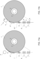
- the unwinding device comprises a counter-roller 16 associated with the spindle 8 and movable (in particular controllable by means of the aforementioned control unit) between an open configuration ( Figure 11a ), in which it is spaced apart from the spindle 8 and from the reel 2 supported, in use, by the latter, and a closed configuration ( Figure 11b ) in which it is contact-pressed (pushed) against such reel 2.
- the counter-roller 16 is actuatable in rotation ( Figure 11b ) for determining a rotation of the reel 2 about the spindle 8 and causing the separation of the initial flap 2a from the reel 2 and the unwinding of the initial flap 2a along the unwinding path T towards the gripping member 11, i.e. towards the grippers 12.
- the unwinding device comprises an electric motor configured to control the rotation of the spindle 8.
- the unwinding device comprises an opening element, configured to cut or remove an adhesive tape which constrains the flap 2a to the rest of the reel 2.
- system 1 further comprises a series of deviating members 23 preferably carried by the separator 22 and configured to guide the initial flap 2a unwinding along the path T.
- the withdrawing of the reel 2 from the storage or receiving station of the assembly 100 takes place in an automated manner, in particular, the storage station comprises automatic warehouses.
- the storage or receiving station is arranged at a machine upstream in the production chain of the electrical energy storage devices.
- the storage or receiving station corresponds to a station in which the reel 2 is completed. In these cases, therefore, the reel 2 is transported directly by a machine that winds it to one that unwinds it.
- the system 1 comprises two support spindles 8, both extending cantilevered from the upright 20.
- the vehicle 7 carries two support spindles 8.
- the vehicle 7 includes a rotatable plate 19 mounted in a movable manner to the upright 20 and to which the spindles 8 are fixed so as to extend cantilevered therefrom.
- the plate 19 is movable, at the change station (i.e. conveniently when the vehicle 7 is in the change station), between:
- the rotatable plate 19 is fixed to the upright 20 in a rotatable manner about a rotation axis A, preferably horizontal (perpendicular to the upright 20).
- the gripping member 11 comprises at least one gripper 12 for each spindle 8.
- the gripping member 11 comprises a pair of grippers 12 for each spindle 8, which operate in accordance with what described above.
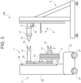
- control unit controls, on the basis of the data received from the sensors, the movement of the vehicle 7 along the pre-established trajectory from the storage or receiving station to the change station ( Figure 3 ).
- the vehicle 7 advances for determining the coupling of the empty spindle 8 to the spindle 5 of the feeding unit 4 which supports the core 17 of the exhausted reel 2 to be changed ( Figure 4 ).
- the feeding unit 4 includes a pushing device 18, preferably one for each spindle 5 and substantially of the same type of the pushing device 13, configured to move the core 17 supported by the spindle 5 towards the spindle 8 (shape) coupled to the latter ( Figure 5 ).
- the pushing device 18 is instead supported by the vehicle 7. In such manner, this prevents modifying to such regard the feeding unit 4.
- the vehicle 7 spaces apart from the feeding unit 4 for decoupling the spindle 8 from the spindle 5 ( Figure 6 ), thus the control unit controls the rotation of the rotatable plate 19, so that the spindle 8 supporting the full reel 2 takes the place of the spindle 8 supporting the core 17 of the exhausted reel 2 and faces the spindle 5 ( Figure 7 ).
- the counter-roller 16 determines the separation and unwinding of the initial flap 2a along the unwinding path T and the relative grippers 12 grip the initial flap 2a ( Figure 7 ). In such condition, the initial flap 2a is tensioned, more in particular the central portion 2c is tensioned, still more in particular, such portion is kept tensioned until the grippers 12 deliver the flap 2a to the gripper 6 of the splicing device.
- the vehicle 7 is controlled for moving close again to the feeding unit 4, so as to determine the coupling of the spindle 8 supporting the full reel 2 to the spindle 5 ( Figure 8 ).
- the central portion 2c is always kept tensioned.
- the pushing device 13 is actuated and the core 17 of the full reel 2 (and therefore the latter) is thus transferred from the spindle 8 to the spindle 5.
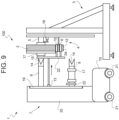
- the grippers 12 are moved from the retracted position to the extracted position ( Figure 9 ).
- the gripper 6 of the splicing device is received between the two grippers 12 and grips the initial flap 2a at the central portion 2c, which, as specified above, is kept tensioned during such operation.
- the delivery of the full reel 2 is at this point accomplished, as well as the delivery of the initial flap 2a to the splicing device.
- the vehicle 7 can thus be decoupled from the feeding unit 4 ( Figure 10 ).
- Figure 12 shows an alternative embodiment of the present invention.
- the system 1 comprises the two spindles 8, the rotatable plate 19 and a gripping member 11' which differs from the gripping member 11 described above only with regard to the following, it being understood that, with the exception of what expressly indicated, the structure and operation of the system 1 are identical to those described in the foregoing.
- the gripping member 11' exactly comprises two grippers 12 (and not four as in the previous case) selectively associable with the first spindle 8 or with the second spindle 8 for gripping the initial flap 2a at the portions 2b spaced apart along the unwinding path T for keeping the central portion 2c tensioned.
- the two grippers 12 are arranged (in particular mounted) on the rotatable plate 19 spaced apart from one another and aligned along a straight line B lying on the plate 19, orthogonal to the rotation axis A and intersecting the rotation axis A, and the unwinding path T extends along the straight line B ( Figure 12 ) .
- the rotatable plate 19 has a circular shape and the straight line B defines a diameter of the rotatable plate 19.
- the two spindles 8 are arranged on opposite sides of the straight line B and the grippers 12 are arranged along the diameter of the plate 19, thus intersecting the rotation centre (rotation axis A) of the plate 19.
- the plate 19 has a whatsoever different shape (rectangular, oval, triangular, etc%), but the straight line B is always arranged so as to lie on the plate 19, intersecting the rotation axis A and orthogonal to the latter.
- the spindles 8 are arranged at the same distance from the straight line B, thus defining an antisymmetric configuration with respect to the straight line B.
- system 1 allows implementing a method for replacing a reel 2 of material for the production of electrical energy storage devices, the method comprising the steps of:
- the gripping step is carried out by means of at least one gripper 12 and the transferring step comprises moving the gripper 12 from a retracted position, in which it grips the initial flap 2a and determines a (places it in) tension thereof, to an advanced position, in which it delivers the tensioned initial flap 2a to the feeding unit 4.
- the gripping step comprises gripping the initial flap 2a at the portions 2b spaced apart from one another along the unwinding path T and the tensioning step comprises tensioning the central portion 2c of the initial flap 2a compressed between the two gripped portions 2b.
- system 1 and the method according to the present invention allow determining an increase in the production speed within the assembly 100, a minimisation of errors possibly made by the operator and a reduction in the risk of accidents of the latter and, therefore, an improvement of the safety conditions of the assembly 100.
- the presence of the counter-roller 16 for automatically unwinding the initial flap 2a and delivering it to the grippers 12 determines a further accentuation of the aforementioned advantages.
Landscapes
- Engineering & Computer Science (AREA)
- Manufacturing & Machinery (AREA)
- Chemical & Material Sciences (AREA)
- Chemical Kinetics & Catalysis (AREA)
- Electrochemistry (AREA)
- General Chemical & Material Sciences (AREA)
- Replacement Of Web Rolls (AREA)
- Transportation (AREA)
- Structural Engineering (AREA)
- Civil Engineering (AREA)
- Life Sciences & Earth Sciences (AREA)
- Geology (AREA)
- Mechanical Engineering (AREA)
Applications Claiming Priority (1)
| Application Number | Priority Date | Filing Date | Title |
|---|---|---|---|
| IT202100018266 | 2021-07-12 |
Publications (2)
| Publication Number | Publication Date |
|---|---|
| EP4119475A1 EP4119475A1 (en) | 2023-01-18 |
| EP4119475B1 true EP4119475B1 (en) | 2024-09-04 |
Family
ID=77989917
Family Applications (1)
| Application Number | Title | Priority Date | Filing Date |
|---|---|---|---|
| EP22183383.3A Active EP4119475B1 (en) | 2021-07-12 | 2022-07-06 | System for replacing a reel of material for the production of electrical energy storage devices and related method |
Country Status (8)
| Country | Link |
|---|---|
| US (1) | US20230010608A1 (pl) |
| EP (1) | EP4119475B1 (pl) |
| JP (1) | JP2023011531A (pl) |
| KR (1) | KR20230010594A (pl) |
| CN (1) | CN115611045A (pl) |
| CA (1) | CA3167274A1 (pl) |
| HU (1) | HUE068160T2 (pl) |
| PL (1) | PL4119475T3 (pl) |
Families Citing this family (15)
| Publication number | Priority date | Publication date | Assignee | Title |
|---|---|---|---|---|
| WO2021129077A1 (zh) * | 2019-12-24 | 2021-07-01 | 无锡先导智能装备股份有限公司 | 自动换卷装置及卷绕设备 |
| US20240243330A1 (en) * | 2023-01-13 | 2024-07-18 | Kye-seol LEE | Automatic supply and replacement device of electrode plate for manufacturing secondary battery |
| US20240322213A1 (en) * | 2023-03-22 | 2024-09-26 | Kye-seol LEE | Secondary battery electrode film and separator supply device |
| KR102739371B1 (ko) * | 2023-03-22 | 2024-12-06 | 이계설 | 이차전지의 양극과 음극의 전극 분리막용 보빈 자동교체장치 |
| IT202300008721A1 (it) * | 2023-05-03 | 2024-11-03 | Manz Italy Srl | Apparato di caricamento di bobine, relativa macchina comprendente l'apparato di caricamento e metodo per la produzione di dispositivi di accumulo di energia elettrica |
| IT202300008679A1 (it) * | 2023-05-03 | 2024-11-03 | Manz Italy Srl | Apparato di caricamento di bobine, relativa macchina comprendente l'apparato di caricamento e metodo per la produzione di dispositivi di accumulo di energia elettrica |
| KR102603219B1 (ko) | 2023-05-22 | 2023-11-16 | 주식회사 에스케이와이에프에이 | 배터리용 릴보빈 이송지그 |
| KR102767395B1 (ko) | 2023-05-26 | 2025-02-14 | 주식회사 에스케이와이에프에이 | 배터리용 릴보빈 이송지그 |
| DE102023206476A1 (de) | 2023-07-07 | 2025-01-09 | Volkswagen Aktiengesellschaft | Vorrichtung zum Wechseln eines Coils oder eines Kerns, Anordnung und Verfahren zum Wechseln eines Coils oder eines Kerns |
| CN116946775A (zh) * | 2023-07-10 | 2023-10-27 | 珠海创智科技有限公司 | 一种卷料取卸料夹手机构 |
| KR20250023872A (ko) | 2023-08-10 | 2025-02-18 | 창운정밀 주식회사 | 배터리용 릴보빈 이송지그 |
| IT202300022593A1 (it) * | 2023-10-27 | 2025-04-27 | Manz Italy Srl | Apparato di trasferimento per bobine, macchina comprendente l'apparato di trasferimento e metodo per la produzione di dispositivi di accumulo di energia elettrica |
| WO2025216604A1 (ko) * | 2024-04-08 | 2025-10-16 | 주식회사 에이아이로보틱스 | 자율주행 방식의 필름 롤 교체 및 연결부착 로봇 |
| KR102742782B1 (ko) * | 2024-06-07 | 2024-12-16 | (주)코윈테크 | 분리 인출 기능을 가진 전극롤 거치 장치 |
| KR102796903B1 (ko) * | 2024-12-05 | 2025-04-17 | (주)코윈테크 | 전극롤 분리 및 인출 장치 |
Family Cites Families (16)
| Publication number | Priority date | Publication date | Assignee | Title |
|---|---|---|---|---|
| GB1592948A (en) * | 1976-12-21 | 1981-07-15 | Masson Scott Thrissell Eng Ltd | Apparatus for web feed |
| DE3812514C2 (de) * | 1988-04-15 | 1998-01-29 | Focke & Co | Verpackungsmaschine mit einem an einem Transportarm angeordneten Transportzapfen für neue Bobinen |
| IT1253922B (it) * | 1991-12-20 | 1995-08-31 | Gd Spa | Carrello per il caricamento di bobine in un dispositivo di alimentazione di una macchina confezionatrice |
| DE19508581B4 (de) * | 1995-03-13 | 2006-04-13 | Focke & Co.(Gmbh & Co. Kg) | Einrichtung zur Handhabung von Bobinen aus Verpackungsmaterial |
| FR2731997B1 (fr) * | 1995-03-22 | 1997-05-09 | Kodak Pathe | Derouleuse de produit en bande |
| US6056232A (en) * | 1997-08-27 | 2000-05-02 | Fuji Photo Film Co., Ltd. | Method of loading film roll on film unwinder shaft and film producing and packaging system |
| US6451145B1 (en) * | 1998-03-09 | 2002-09-17 | Frontier Industrial Technology, Inc. | Web splicing system |
| AUPR636201A0 (en) * | 2001-07-13 | 2001-08-02 | Cryovac Australia Pty Ltd | Mounting jig and trolley for mounting and optionally transporting a roll of material |
| US7331542B2 (en) * | 2003-05-09 | 2008-02-19 | Intellipack | Film unwind system with hinged spindle and electronic control of web tension |
| US7306184B2 (en) * | 2003-09-15 | 2007-12-11 | Tafel Brian L | Splicing vehicle |
| DE102013110944A1 (de) * | 2013-10-02 | 2015-04-02 | Krones Aktiengesellschaft | Verfahren und Vorrichtung zum Wechseln von Trägereinheiten mit auf Vorratsrollen aufgewickeltem flächigem Verpackungsmaterial innerhalb einer Verpackungsmaschine |
| WO2019207436A1 (en) * | 2018-04-26 | 2019-10-31 | I.M.A. Industria Macchine Automatiche S.P.A. | Method for reel changing in automatic machines. |
| KR102538070B1 (ko) * | 2018-11-30 | 2023-05-30 | 엘지전자 주식회사 | 전극롤 공급기 |
| KR102858408B1 (ko) * | 2021-02-26 | 2025-09-10 | 에스케이온 주식회사 | 공급소재 자동교체장치 및 자동교체방법 |
| US20240243330A1 (en) * | 2023-01-13 | 2024-07-18 | Kye-seol LEE | Automatic supply and replacement device of electrode plate for manufacturing secondary battery |
| US20240322213A1 (en) * | 2023-03-22 | 2024-09-26 | Kye-seol LEE | Secondary battery electrode film and separator supply device |
-
2022
- 2022-07-06 EP EP22183383.3A patent/EP4119475B1/en active Active
- 2022-07-06 HU HUE22183383A patent/HUE068160T2/hu unknown
- 2022-07-06 PL PL22183383.3T patent/PL4119475T3/pl unknown
- 2022-07-07 CA CA3167274A patent/CA3167274A1/en active Pending
- 2022-07-11 KR KR1020220084938A patent/KR20230010594A/ko active Pending
- 2022-07-11 CN CN202210813957.2A patent/CN115611045A/zh active Pending
- 2022-07-11 JP JP2022111169A patent/JP2023011531A/ja active Pending
- 2022-07-11 US US17/861,376 patent/US20230010608A1/en not_active Abandoned
Also Published As
| Publication number | Publication date |
|---|---|
| CN115611045A (zh) | 2023-01-17 |
| US20230010608A1 (en) | 2023-01-12 |
| JP2023011531A (ja) | 2023-01-24 |
| HUE068160T2 (hu) | 2024-12-28 |
| KR20230010594A (ko) | 2023-01-19 |
| CA3167274A1 (en) | 2023-01-12 |
| EP4119475A1 (en) | 2023-01-18 |
| PL4119475T3 (pl) | 2024-12-23 |
Similar Documents
| Publication | Publication Date | Title |
|---|---|---|
| EP4119475B1 (en) | System for replacing a reel of material for the production of electrical energy storage devices and related method | |
| US4948060A (en) | Automatic web roll handling system for splicing | |
| KR20010086203A (ko) | 연속 와인더 | |
| EP1380526B9 (en) | Web winding method and apparatus therefor | |
| US4555070A (en) | Method and apparatus for unwinding and splicing successive rolls | |
| GB1580969A (en) | Accumulator for a web transportation apparatus and apparatus for the treatment of a web of ribbon or sheet material including the same | |
| EP4370456B1 (en) | Automatic unwinder of flexible materials wound on reels and process for feeding an operating machine with said flexible materials | |
| EP4259564B1 (en) | Plant and process for handling cardboard reels | |
| EP0327048B1 (en) | Winding apparatus for sheet-shaped molding material | |
| US20250219124A1 (en) | Apparatus and relative method of winding a strip of material, in particular for the production of electrical energy storage devices | |
| US4575016A (en) | Continuous ribbon feed method and system | |
| CN212245436U (zh) | 一种原材料的供料及切换装置 | |
| JP3943915B2 (ja) | ウエブの巻き取り巻き戻し装置及びこれを備えた製紙設備 | |
| JP4053177B2 (ja) | 帯状部材の切替巻出し装置 | |
| EP4259565A1 (en) | Plant and method for the movement of cardboard cores | |
| KR101062139B1 (ko) | 다층 어셈블리 제조장치에서의 시트 구동 제어용 장치 | |
| CA2160426C (en) | Apparatus and process for supplying printed products to a processing section | |
| EP4259563B1 (en) | Plant and process for the movement of cardboard webs | |
| IT9021223A1 (it) | Dispositivo per l'approvvigionamento automatizzato di bobine di nastro magnetico su macchine confezionatrici di cassette a nastro | |
| CN113573998B (zh) | 用于替换退绕机中的卷筒的装置以及相关方法 | |
| WO2024161236A1 (en) | Splicing apparatus for splicing material bands for the production of power storage devices, machine and related splicing method | |
| JP4245241B2 (ja) | プラスチックフィルムの連続巻取り方法および装置 | |
| CA1297464C (en) | Method of, and apparatus for, processing printed products, especially newspapers, periodicals and the like | |
| IT202300015294A1 (it) | Macchina e metodo per avvolgere un carico | |
| WO2021001774A1 (en) | Roller blind manufacturing machine and method |
Legal Events
| Date | Code | Title | Description |
|---|---|---|---|
| PUAI | Public reference made under article 153(3) epc to a published international application that has entered the european phase |
Free format text: ORIGINAL CODE: 0009012 |
|
| STAA | Information on the status of an ep patent application or granted ep patent |
Free format text: STATUS: THE APPLICATION HAS BEEN PUBLISHED |
|
| AK | Designated contracting states |
Kind code of ref document: A1 Designated state(s): AL AT BE BG CH CY CZ DE DK EE ES FI FR GB GR HR HU IE IS IT LI LT LU LV MC MK MT NL NO PL PT RO RS SE SI SK SM TR |
|
| STAA | Information on the status of an ep patent application or granted ep patent |
Free format text: STATUS: REQUEST FOR EXAMINATION WAS MADE |
|
| 17P | Request for examination filed |
Effective date: 20230718 |
|
| RBV | Designated contracting states (corrected) |
Designated state(s): AL AT BE BG CH CY CZ DE DK EE ES FI FR GB GR HR HU IE IS IT LI LT LU LV MC MK MT NL NO PL PT RO RS SE SI SK SM TR |
|
| GRAP | Despatch of communication of intention to grant a patent |
Free format text: ORIGINAL CODE: EPIDOSNIGR1 |
|
| STAA | Information on the status of an ep patent application or granted ep patent |
Free format text: STATUS: GRANT OF PATENT IS INTENDED |
|
| RIC1 | Information provided on ipc code assigned before grant |
Ipc: H01M 4/04 20060101ALI20240229BHEP Ipc: H01M 10/04 20060101ALI20240229BHEP Ipc: B65H 19/10 20060101ALI20240229BHEP Ipc: B66F 9/075 20060101ALI20240229BHEP Ipc: B65H 19/12 20060101AFI20240229BHEP |
|
| INTG | Intention to grant announced |
Effective date: 20240322 |
|
| P01 | Opt-out of the competence of the unified patent court (upc) registered |
Effective date: 20240529 |
|
| GRAS | Grant fee paid |
Free format text: ORIGINAL CODE: EPIDOSNIGR3 |
|
| GRAA | (expected) grant |
Free format text: ORIGINAL CODE: 0009210 |
|
| STAA | Information on the status of an ep patent application or granted ep patent |
Free format text: STATUS: THE PATENT HAS BEEN GRANTED |
|
| AK | Designated contracting states |
Kind code of ref document: B1 Designated state(s): AL AT BE BG CH CY CZ DE DK EE ES FI FR GB GR HR HU IE IS IT LI LT LU LV MC MK MT NL NO PL PT RO RS SE SI SK SM TR |
|
| REG | Reference to a national code |
Ref country code: GB Ref legal event code: FG4D |
|
| REG | Reference to a national code |
Ref country code: CH Ref legal event code: EP |
|
| REG | Reference to a national code |
Ref country code: IE Ref legal event code: FG4D |
|
| REG | Reference to a national code |
Ref country code: DE Ref legal event code: R096 Ref document number: 602022005811 Country of ref document: DE |
|
| PGFP | Annual fee paid to national office [announced via postgrant information from national office to epo] |
Ref country code: HU Payment date: 20240706 Year of fee payment: 3 |
|
| REG | Reference to a national code |
Ref country code: SE Ref legal event code: TRGR |
|
| REG | Reference to a national code |
Ref country code: LT Ref legal event code: MG9D |
|
| REG | Reference to a national code |
Ref country code: HU Ref legal event code: AG4A Ref document number: E068160 Country of ref document: HU |
|
| REG | Reference to a national code |
Ref country code: NL Ref legal event code: MP Effective date: 20240904 |
|
| PG25 | Lapsed in a contracting state [announced via postgrant information from national office to epo] |
Ref country code: NO Free format text: LAPSE BECAUSE OF FAILURE TO SUBMIT A TRANSLATION OF THE DESCRIPTION OR TO PAY THE FEE WITHIN THE PRESCRIBED TIME-LIMIT Effective date: 20241204 |
|
| PG25 | Lapsed in a contracting state [announced via postgrant information from national office to epo] |
Ref country code: GR Free format text: LAPSE BECAUSE OF FAILURE TO SUBMIT A TRANSLATION OF THE DESCRIPTION OR TO PAY THE FEE WITHIN THE PRESCRIBED TIME-LIMIT Effective date: 20241205 Ref country code: FI Free format text: LAPSE BECAUSE OF FAILURE TO SUBMIT A TRANSLATION OF THE DESCRIPTION OR TO PAY THE FEE WITHIN THE PRESCRIBED TIME-LIMIT Effective date: 20240904 |
|
| PG25 | Lapsed in a contracting state [announced via postgrant information from national office to epo] |
Ref country code: BG Free format text: LAPSE BECAUSE OF FAILURE TO SUBMIT A TRANSLATION OF THE DESCRIPTION OR TO PAY THE FEE WITHIN THE PRESCRIBED TIME-LIMIT Effective date: 20240904 |
|
| PG25 | Lapsed in a contracting state [announced via postgrant information from national office to epo] |
Ref country code: LV Free format text: LAPSE BECAUSE OF FAILURE TO SUBMIT A TRANSLATION OF THE DESCRIPTION OR TO PAY THE FEE WITHIN THE PRESCRIBED TIME-LIMIT Effective date: 20240904 |
|
| PG25 | Lapsed in a contracting state [announced via postgrant information from national office to epo] |
Ref country code: HR Free format text: LAPSE BECAUSE OF FAILURE TO SUBMIT A TRANSLATION OF THE DESCRIPTION OR TO PAY THE FEE WITHIN THE PRESCRIBED TIME-LIMIT Effective date: 20240904 |
|
| PG25 | Lapsed in a contracting state [announced via postgrant information from national office to epo] |
Ref country code: ES Free format text: LAPSE BECAUSE OF FAILURE TO SUBMIT A TRANSLATION OF THE DESCRIPTION OR TO PAY THE FEE WITHIN THE PRESCRIBED TIME-LIMIT Effective date: 20240904 Ref country code: RS Free format text: LAPSE BECAUSE OF FAILURE TO SUBMIT A TRANSLATION OF THE DESCRIPTION OR TO PAY THE FEE WITHIN THE PRESCRIBED TIME-LIMIT Effective date: 20241204 |
|
| PG25 | Lapsed in a contracting state [announced via postgrant information from national office to epo] |
Ref country code: RS Free format text: LAPSE BECAUSE OF FAILURE TO SUBMIT A TRANSLATION OF THE DESCRIPTION OR TO PAY THE FEE WITHIN THE PRESCRIBED TIME-LIMIT Effective date: 20241204 Ref country code: NO Free format text: LAPSE BECAUSE OF FAILURE TO SUBMIT A TRANSLATION OF THE DESCRIPTION OR TO PAY THE FEE WITHIN THE PRESCRIBED TIME-LIMIT Effective date: 20241204 Ref country code: LV Free format text: LAPSE BECAUSE OF FAILURE TO SUBMIT A TRANSLATION OF THE DESCRIPTION OR TO PAY THE FEE WITHIN THE PRESCRIBED TIME-LIMIT Effective date: 20240904 Ref country code: HR Free format text: LAPSE BECAUSE OF FAILURE TO SUBMIT A TRANSLATION OF THE DESCRIPTION OR TO PAY THE FEE WITHIN THE PRESCRIBED TIME-LIMIT Effective date: 20240904 Ref country code: GR Free format text: LAPSE BECAUSE OF FAILURE TO SUBMIT A TRANSLATION OF THE DESCRIPTION OR TO PAY THE FEE WITHIN THE PRESCRIBED TIME-LIMIT Effective date: 20241205 Ref country code: FI Free format text: LAPSE BECAUSE OF FAILURE TO SUBMIT A TRANSLATION OF THE DESCRIPTION OR TO PAY THE FEE WITHIN THE PRESCRIBED TIME-LIMIT Effective date: 20240904 Ref country code: ES Free format text: LAPSE BECAUSE OF FAILURE TO SUBMIT A TRANSLATION OF THE DESCRIPTION OR TO PAY THE FEE WITHIN THE PRESCRIBED TIME-LIMIT Effective date: 20240904 Ref country code: BG Free format text: LAPSE BECAUSE OF FAILURE TO SUBMIT A TRANSLATION OF THE DESCRIPTION OR TO PAY THE FEE WITHIN THE PRESCRIBED TIME-LIMIT Effective date: 20240904 |
|
| REG | Reference to a national code |
Ref country code: AT Ref legal event code: MK05 Ref document number: 1720201 Country of ref document: AT Kind code of ref document: T Effective date: 20240904 |
|
| PG25 | Lapsed in a contracting state [announced via postgrant information from national office to epo] |
Ref country code: NL Free format text: LAPSE BECAUSE OF FAILURE TO SUBMIT A TRANSLATION OF THE DESCRIPTION OR TO PAY THE FEE WITHIN THE PRESCRIBED TIME-LIMIT Effective date: 20240904 |
|
| PG25 | Lapsed in a contracting state [announced via postgrant information from national office to epo] |
Ref country code: PT Free format text: LAPSE BECAUSE OF FAILURE TO SUBMIT A TRANSLATION OF THE DESCRIPTION OR TO PAY THE FEE WITHIN THE PRESCRIBED TIME-LIMIT Effective date: 20250106 Ref country code: IS Free format text: LAPSE BECAUSE OF FAILURE TO SUBMIT A TRANSLATION OF THE DESCRIPTION OR TO PAY THE FEE WITHIN THE PRESCRIBED TIME-LIMIT Effective date: 20250104 |
|
| PG25 | Lapsed in a contracting state [announced via postgrant information from national office to epo] |
Ref country code: SM Free format text: LAPSE BECAUSE OF FAILURE TO SUBMIT A TRANSLATION OF THE DESCRIPTION OR TO PAY THE FEE WITHIN THE PRESCRIBED TIME-LIMIT Effective date: 20240904 Ref country code: RO Free format text: LAPSE BECAUSE OF FAILURE TO SUBMIT A TRANSLATION OF THE DESCRIPTION OR TO PAY THE FEE WITHIN THE PRESCRIBED TIME-LIMIT Effective date: 20240904 |
|
| PG25 | Lapsed in a contracting state [announced via postgrant information from national office to epo] |
Ref country code: EE Free format text: LAPSE BECAUSE OF FAILURE TO SUBMIT A TRANSLATION OF THE DESCRIPTION OR TO PAY THE FEE WITHIN THE PRESCRIBED TIME-LIMIT Effective date: 20240904 Ref country code: AT Free format text: LAPSE BECAUSE OF FAILURE TO SUBMIT A TRANSLATION OF THE DESCRIPTION OR TO PAY THE FEE WITHIN THE PRESCRIBED TIME-LIMIT Effective date: 20240904 |
|
| PG25 | Lapsed in a contracting state [announced via postgrant information from national office to epo] |
Ref country code: CZ Free format text: LAPSE BECAUSE OF FAILURE TO SUBMIT A TRANSLATION OF THE DESCRIPTION OR TO PAY THE FEE WITHIN THE PRESCRIBED TIME-LIMIT Effective date: 20240904 |
|
| PG25 | Lapsed in a contracting state [announced via postgrant information from national office to epo] |
Ref country code: SK Free format text: LAPSE BECAUSE OF FAILURE TO SUBMIT A TRANSLATION OF THE DESCRIPTION OR TO PAY THE FEE WITHIN THE PRESCRIBED TIME-LIMIT Effective date: 20240904 |
|
| REG | Reference to a national code |
Ref country code: DE Ref legal event code: R097 Ref document number: 602022005811 Country of ref document: DE |
|
| PG25 | Lapsed in a contracting state [announced via postgrant information from national office to epo] |
Ref country code: DK Free format text: LAPSE BECAUSE OF FAILURE TO SUBMIT A TRANSLATION OF THE DESCRIPTION OR TO PAY THE FEE WITHIN THE PRESCRIBED TIME-LIMIT Effective date: 20240904 |
|
| PLBE | No opposition filed within time limit |
Free format text: ORIGINAL CODE: 0009261 |
|
| STAA | Information on the status of an ep patent application or granted ep patent |
Free format text: STATUS: NO OPPOSITION FILED WITHIN TIME LIMIT |
|
| 26N | No opposition filed |
Effective date: 20250605 |
|
| PGFP | Annual fee paid to national office [announced via postgrant information from national office to epo] |
Ref country code: IT Payment date: 20250731 Year of fee payment: 4 |