EP4119214B1 - Device for detecting filter blockages - Google Patents
Device for detecting filter blockages Download PDFInfo
- Publication number
- EP4119214B1 EP4119214B1 EP22194635.3A EP22194635A EP4119214B1 EP 4119214 B1 EP4119214 B1 EP 4119214B1 EP 22194635 A EP22194635 A EP 22194635A EP 4119214 B1 EP4119214 B1 EP 4119214B1
- Authority
- EP
- European Patent Office
- Prior art keywords
- setpoint
- fan
- actual
- filter
- value pairs
- Prior art date
- Legal status (The legal status is an assumption and is not a legal conclusion. Google has not performed a legal analysis and makes no representation as to the accuracy of the status listed.)
- Active
Links
- 230000004672 jump response Effects 0.000 claims 1
- 238000011109 contamination Methods 0.000 description 31
- 238000000034 method Methods 0.000 description 8
- 238000001514 detection method Methods 0.000 description 7
- 238000011156 evaluation Methods 0.000 description 7
- 230000008859 change Effects 0.000 description 5
- 230000006399 behavior Effects 0.000 description 3
- 230000008569 process Effects 0.000 description 3
- 230000004044 response Effects 0.000 description 3
- 230000032683 aging Effects 0.000 description 2
- 230000006870 function Effects 0.000 description 2
- 238000005259 measurement Methods 0.000 description 2
- 238000009423 ventilation Methods 0.000 description 2
- 238000004887 air purification Methods 0.000 description 1
- 230000005540 biological transmission Effects 0.000 description 1
- 238000007664 blowing Methods 0.000 description 1
- 238000004364 calculation method Methods 0.000 description 1
- 238000009795 derivation Methods 0.000 description 1
- 238000011161 development Methods 0.000 description 1
- 230000018109 developmental process Effects 0.000 description 1
- 230000000694 effects Effects 0.000 description 1
- 238000005516 engineering process Methods 0.000 description 1
- 230000003760 hair shine Effects 0.000 description 1
- 238000009434 installation Methods 0.000 description 1
- 230000002452 interceptive effect Effects 0.000 description 1
- 239000002245 particle Substances 0.000 description 1
- 230000010363 phase shift Effects 0.000 description 1
- 238000012545 processing Methods 0.000 description 1
- 230000005855 radiation Effects 0.000 description 1
- 230000009467 reduction Effects 0.000 description 1
- 230000011664 signaling Effects 0.000 description 1
Images
Classifications
-
- B—PERFORMING OPERATIONS; TRANSPORTING
- B01—PHYSICAL OR CHEMICAL PROCESSES OR APPARATUS IN GENERAL
- B01D—SEPARATION
- B01D46/00—Filters or filtering processes specially modified for separating dispersed particles from gases or vapours
- B01D46/0084—Filters or filtering processes specially modified for separating dispersed particles from gases or vapours provided with safety means
- B01D46/0086—Filter condition indicators
-
- B—PERFORMING OPERATIONS; TRANSPORTING
- B01—PHYSICAL OR CHEMICAL PROCESSES OR APPARATUS IN GENERAL
- B01D—SEPARATION
- B01D35/00—Filtering devices having features not specifically covered by groups B01D24/00 - B01D33/00, or for applications not specifically covered by groups B01D24/00 - B01D33/00; Auxiliary devices for filtration; Filter housing constructions
- B01D35/14—Safety devices specially adapted for filtration; Devices for indicating clogging
- B01D35/143—Filter condition indicators
-
- B—PERFORMING OPERATIONS; TRANSPORTING
- B01—PHYSICAL OR CHEMICAL PROCESSES OR APPARATUS IN GENERAL
- B01D—SEPARATION
- B01D46/00—Filters or filtering processes specially modified for separating dispersed particles from gases or vapours
- B01D46/42—Auxiliary equipment or operation thereof
- B01D46/44—Auxiliary equipment or operation thereof controlling filtration
- B01D46/46—Auxiliary equipment or operation thereof controlling filtration automatic
-
- B—PERFORMING OPERATIONS; TRANSPORTING
- B01—PHYSICAL OR CHEMICAL PROCESSES OR APPARATUS IN GENERAL
- B01D—SEPARATION
- B01D2279/00—Filters adapted for separating dispersed particles from gases or vapours specially modified for specific uses
- B01D2279/50—Filters adapted for separating dispersed particles from gases or vapours specially modified for specific uses for air conditioning
-
- H—ELECTRICITY
- H02—GENERATION; CONVERSION OR DISTRIBUTION OF ELECTRIC POWER
- H02P—CONTROL OR REGULATION OF ELECTRIC MOTORS, ELECTRIC GENERATORS OR DYNAMO-ELECTRIC CONVERTERS; CONTROLLING TRANSFORMERS, REACTORS OR CHOKE COILS
- H02P27/00—Arrangements or methods for the control of AC motors characterised by the kind of supply voltage
- H02P27/04—Arrangements or methods for the control of AC motors characterised by the kind of supply voltage using variable-frequency supply voltage, e.g. inverter or converter supply voltage
- H02P27/06—Arrangements or methods for the control of AC motors characterised by the kind of supply voltage using variable-frequency supply voltage, e.g. inverter or converter supply voltage using dc to ac converters or inverters
- H02P27/08—Arrangements or methods for the control of AC motors characterised by the kind of supply voltage using variable-frequency supply voltage, e.g. inverter or converter supply voltage using dc to ac converters or inverters with pulse width modulation
-
- Y—GENERAL TAGGING OF NEW TECHNOLOGICAL DEVELOPMENTS; GENERAL TAGGING OF CROSS-SECTIONAL TECHNOLOGIES SPANNING OVER SEVERAL SECTIONS OF THE IPC; TECHNICAL SUBJECTS COVERED BY FORMER USPC CROSS-REFERENCE ART COLLECTIONS [XRACs] AND DIGESTS
- Y10—TECHNICAL SUBJECTS COVERED BY FORMER USPC
- Y10S—TECHNICAL SUBJECTS COVERED BY FORMER USPC CROSS-REFERENCE ART COLLECTIONS [XRACs] AND DIGESTS
- Y10S116/00—Signals and indicators
- Y10S116/25—Air filter condition indicator
Definitions
- the invention relates to a device for detecting and measuring filter contamination.
- filters are typically used in addition to fans for air purification. With many devices, the user cannot easily determine from the outside whether the filter is already so dirty or clogged with dirt particles that it needs to be cleaned or replaced.
- the determination and measurement of filter contamination is carried out while the vehicle is stationary, for example. B. carried out with additional sensors or devices, such as. B. with an infrared sensor to measure filter contamination.
- the degree of contamination is e.g. B. measured in such a way that an infrared light source shines into the filter and is reflected and measured on the opposite side by the reflection mirror attached there. If the filter is slightly dirty, a lot of light is reflected; if it is very dirty, hardly any light reaches the measuring point.
- the electronics calculate the degree of contamination from this difference in radiation intensity. If no more light is reflected, it switches off, for example. B. also cuts off the power supply to the fan in the affected air duct.
- Another method is to measure the differential pressure before and after the filter, whereby the differential pressure can be measured as the filter becomes more dirty, allowing conclusions to be drawn about the degree of contamination.
- the disadvantage here is that additional measuring devices are required and the differential pressure can also change due to other fluidic influences.
- From the DE 4037685 A1 is a filter control device for interior air filters of motor vehicles with an electric blower motor with a filter arranged in the suction area, an electronic blower motor speed control.
- the blower motor speed control and a climate control unit are connected to outputs of a central control unit, via which an automatic filter control process can be carried out using a control program and to whose inputs signal processing devices and a starting current meter are connected via analog/digital converters. This also requires separate measuring and control devices, which should be avoided for cost reasons.
- Another device for determining a filter condition is in the WO 02/19511 disclosed.
- the degree of filter contamination also influences the required torque of the fan in a ventilation system, so that the motor parameters have to be constantly changed and the fan also increasingly works in a less optimal operating range.
- the invention is therefore based on the object of overcoming the aforementioned disadvantages and of providing a simple, cost-effective concept for the detection and/or measurement of filter contamination, which can be implemented with a small number of components.
- a fan such as a fan
- a radial fan builds up pressure (“pressure accumulator"), and when idling this pressure can relax again and thus affects the braking behavior of the fan.
- pressure is built up and reduced more quickly or more slowly.
- a basic idea of the present invention is to provide a device for carrying out a detection method for detecting filter contamination of an air filter in a flow area of a fan, in which the connection between the power consumption of the fan and its actual level of control (PWM control) as well as the actual speed can be used to draw conclusions about filter contamination.
- PWM control actual level of control
- a characteristic curve can be calibrated by importing an existing characteristic curve, for example via a data bus, using data from a database that is appropriate for the installation situation and the selected filter type.
- the intermediate circuit voltage and the intermediate circuit current are recorded. This data is stored in the fan's memory and an immediate conclusion can be drawn about the filter contamination.
- a positive side effect of the solution according to the invention is that the aging process of the fan is slowed down. Aging includes, for example, the wear of the bearing, for which there are already appropriate service life calculation models. Alternatively, parameters that determine bearing life can also be measured using appropriate sensors.
- the fan compares the current actual speed and the actual modulation level with the corresponding stored target data during operation.
- a value pair comparison takes place. If the modulation level corresponding to a stored speed value deviates from the current actual modulation level of the current actual speed value by more than a predetermined permissible deviation value, this condition is evaluated as filter contamination, since if the filter is dirty, the modulation level must be increased in order to achieve a desired speed that would occur if the filter were not or less dirty.
- a tolerance band with maximum values and minimum values is defined.
- a dirty filter can be reported as a warning on the bus, as a flashing code on an LED or as an error signaling relay that has been set.
- the error signal can also be output externally via a suitable interface.
- the solution according to the invention only provides an evaluation unit in which relationships between speed and modulation level, as well as the intermediate circuit voltage and the intermediate circuit current are used.
- the degree of contamination can be calculated if the deviation of the actual values from the target values has a linear behavior and the absolute deviation is determined.
- the value determined in this way can be queried via a data bus or present as an analog voltage signal at a signal output.
- a low voltage would be considered as low contamination and a maximum permissible voltage of the analog signal as maximum permissible contamination.
- the time-discrete or continuous recording of the values over time can also be evaluated and from the derivation over time, a gradual change in filter contamination up to a maximum permissible degree of contamination can also be detected. If the first derivative with respect to time is approximately constant, a continuous and increasing filter contamination can be derived from this.
- the rate of change of the PWM signal when blowing out the filter during reverse operation is evaluated, whereby the fact that fan wheels are typically technically optimized for the forward direction of rotation is compensated for by taking into account the specific parameters of the fan and the fans therefore only achieve a limited air performance in the reverse direction of rotation.
- a jump in speed is given to the fan, the step response of which is recorded and evaluated.
- the filter acts like a low pass.
- the output parameter here is the actual PWM signal. If the filter is slightly dirty, it will subside very quickly; if the filter is very dirty, it will only subside slowly. The rate of change of the actual PWM is therefore considered.
- This configuration is similar to the aforementioned method of reverse operation, except that there is no need to compensate for the poorer air performance of the fan wheels in reverse operation.
- the filter is additionally described by mathematical parameters in a model.
- the step response provides actual values of these parameters, which are then compared with the ideal values from the model.
- filter parameters can be obtained, among other things, using Kalman filters or other gradient methods. An evaluation of the trend over time also takes place.
- a further embodiment of the invention provides that the fan can be used as a loudspeaker using its blades through targeted modulation of the motor current with a sinusoidal carrier signal of known phase and amplitude. It is the property of a loudspeaker that it can also receive vibrations and therefore sounds.
- the one from the fan The tones received are in turn expressed in changes in the motor current, to the extent that a phase shift and amplitude reduction occurs in the motor current in addition to the emitted signals.
- a filter now attenuates these ultrasonic signals depending on how dirty it is, so that the received signal provides information about the degree of contamination in both amplitude and phase position.
- the signals in the current of the fan motor can be evaluated, for example, by correlating the sent signal with the received signal. Interfering signals can also be hidden by varying the transmission frequency.
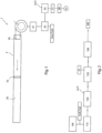
- the Fig.1 shows a schematic view of an embodiment of a device 1 for detecting filter contamination in the filter system 2, wherein the filter system 2 consists of at least one air filter 10 installed in an air duct 20 and an electrically controlled fan 30 for generating an air flow in the air duct 20.
- the device 1 has a motor control 40 for controlling the fan motor, wherein a PWM control 32 is provided for speed control.
- an evaluation device 50 is provided for determining the actual speed n i of the fan 30 as a function of the actual control level (duty factor) of the motor current in order to achieve the current speed n i .
- setpoint pairs n setpoint , T setpoint are also stored for the setpoint speed n setpoint of the filter system 2 at a certain modulation level T setpoint .
- a comparator 51 is provided in the device in order to compare the respective actual value pairs n i , T i with the stored target value pairs n target , T target and from this to determine the degree of filter contamination of the air filter 10. As soon as the deviation is greater than a predetermined limit value in a tolerance band, a signal is output to the LED light 61 via the interface 60, indicating unacceptable filter contamination.
- Fig. 2 a schematic representation of the steps of the detection method for determining filter contamination of a filter system is shown, which is carried out using the device 1 Fig. 1 can be carried out.
- the procedure involves the following steps.
- the engine characteristic curve relating to the speed is recorded or imported as a function of the modulation level in the filter system 2 in which the air filter 10 is not contaminated, for example. B. when starting up the system or changing the filter.
- step 110 These value pairs are stored in step 110 as setpoint pairs n target , T target in a data memory of the device 1.
- the actual speed n i of the fan 30 and the actual control level T i of the motor current are determined in a step 120 to achieve the current actual speed n i .
- the actual value pairs n i , T i are compared with the comparator 51 of the device 1 with the stored setpoint pairs n setpoint , T setpoint .
- step 140 the determination is made as to whether the determined deviation of the actual value pairs n i , T i from the target value pairs n target , T target exceeds a maximum predetermined deviation.
- the deviation can be determined as a band deviation in a permissible tolerance band, whereby either the speed is too low at a certain power consumption and thus a certain duty cycle, or whether too high a duty cycle is necessary to achieve a certain speed.
- the deviation of the actual values from the target values has a linear behavior over time, the increasing deviation can be used to predict not only the current filter clogging, but also the point in time of maximum permissible contamination at which a filter change should take place .
- Detection method with a device according to the invention according to feature 1 the degree of filter contamination being obtained directly from the power consumption of the fan motor 31 without the use of sensors by comparing the actual power consumption with a defined target power consumption of the comparatively uncontaminated filter system.
- the degree of filter contamination is optionally evaluated both from the power consumption of the fan and from a stored fan characteristic curve.
- the intermediate circuit voltage and the intermediate circuit current are also recorded and these data are used to evaluate the degree of filter contamination.
- the message of a dirty air filter 30 is output as a signal when the deviation of the actual values from the target values is exceeded.
- the direction of rotation of the fan is reversed from the intended direction of rotation for a defined time and the actual level of modulation, the actual speed and the intermediate circuit current and the intermediate circuit voltage are continuously recorded.
- a speed jump is initiated on the fan, preferably by means of a motor control, and its step response is recorded and evaluated.
Description
Die Erfindung betrifft eine Vorrichtung zur Detektion und Messung einer Filterverschmutzung.The invention relates to a device for detecting and measuring filter contamination.
In lufttechnischen Anlagen werden neben Ventilatoren typischerweise Filter zur Luftreinigung eingesetzt. Bei vielen Geräten kann der Anwender von außen nicht ohne weiteres feststellen ob der Filter bereits so verschmutzt oder mit Schmutzpartikeln zugesetzt ist, dass er gereinigt oder ausgetauscht werden müsste.In ventilation systems, filters are typically used in addition to fans for air purification. With many devices, the user cannot easily determine from the outside whether the filter is already so dirty or clogged with dirt particles that it needs to be cleaned or replaced.
Die Feststellung und Messung der Filterverschmutzung wird im Stand z. B. mit zusätzlichen Sensoren oder Einrichtungen durchgeführt, wie z. B. mit einem Infrarotsensor zur Messung der Filterverschmutzung. Mit einem Infrarotfilter wird der Verschmutzungsgrad z. B. in der Weise gemessen, dass eine Infrarotlichtquelle in den Filter hineinstrahlt und auf der gegenüberliegenden Seite durch den dort angebrachten Reflektionsspiegel zurückgeworfen und gemessen wird. Ist der Filter wenig verschmutzt wird viel Licht reflektiert, ist er stark verschmutzt kommt am Messpunkt kaum noch Licht an. Aus dieser Differenz der Strahlungsstärke errechnet die Elektronik den Grad der Verschmutzung. Wird kein Licht mehr reflektiert, schaltet sie z. B. auch die Stromversorgung des Ventilators in dem betroffenen Luftkanal ab.The determination and measurement of filter contamination is carried out while the vehicle is stationary, for example. B. carried out with additional sensors or devices, such as. B. with an infrared sensor to measure filter contamination. With an infrared filter, the degree of contamination is e.g. B. measured in such a way that an infrared light source shines into the filter and is reflected and measured on the opposite side by the reflection mirror attached there. If the filter is slightly dirty, a lot of light is reflected; if it is very dirty, hardly any light reaches the measuring point. The electronics calculate the degree of contamination from this difference in radiation intensity. If no more light is reflected, it switches off, for example. B. also cuts off the power supply to the fan in the affected air duct.
Eine andere Methode ist die Differenzdruckmessung vor und nach dem Filter, wobei sich der Differenzdruck mit zunehmender Filterverschmutzung messen lässt und daraus Rückschlüsse auf den Grad der Verschmutzung ergeben. Nachteilig ist dabei, dass es zusätzlicher Messeinrichtungen bedarf und sich der Differenzdruck auch auf Grund anderer strömungstechnischer Einflüssen ändern kann.Another method is to measure the differential pressure before and after the filter, whereby the differential pressure can be measured as the filter becomes more dirty, allowing conclusions to be drawn about the degree of contamination. The disadvantage here is that additional measuring devices are required and the differential pressure can also change due to other fluidic influences.
Aus der
Eine weitere Vorrichtung zur Bestimmung eines Filterzustands ist in der
Der Filterverschmutzungsgrad beeinflusst ferner das erforderliche Drehmoment des Ventilators in einer lufttechnischen Anlage, so dass die Motorparameter permanent verändert werden müssen und der Ventilator auch zunehmend in einem weniger optimalen Betriebsbereich arbeitet.The degree of filter contamination also influences the required torque of the fan in a ventilation system, so that the motor parameters have to be constantly changed and the fan also increasingly works in a less optimal operating range.
Der Erfindung liegt deshalb die Aufgabe zugrunde, vorbesagte Nachteile zu überwinden und ein einfaches, kostengünstiges Konzept für die Detektion und/oder Messung einer Filterverschmutzung vorzusehen, welches mit einer geringen Anzahl an Komponenten realisierbar ist.The invention is therefore based on the object of overcoming the aforementioned disadvantages and of providing a simple, cost-effective concept for the detection and/or measurement of filter contamination, which can be implemented with a small number of components.
Diese Aufgabe wird durch die Merkmalskombination gemäß Anspruch 1 gelöst.This task is solved by the combination of features according to claim 1.
In einem geschlossenen Luftströmungskanal oder Raum baut ein Ventilator, wie z. B. ein Radialventilator einen Druck auf ("Druckspeicher"), im Leerlauf kann sich dieser Druck wieder entspannen und wirkt sich so auf das Bremsverhalten des Ventilators aus. Je nach Verschmutzungsgrad und Luftdurchlass des Filters wird der Druck schneller oder langsamer auf- und abgebaut.In a closed air flow duct or room, a fan, such as a fan, is installed. For example, a radial fan builds up pressure ("pressure accumulator"), and when idling this pressure can relax again and thus affects the braking behavior of the fan. Depending on the degree of contamination and the air passage of the filter, the pressure is built up and reduced more quickly or more slowly.
Ein Grundgedanke der vorliegenden Erfindung besteht darin, eine Vorrichtung zur Durchführung eines Detektionsverfahrens zum Erkennen einer Filterverschmutzung eines Luftfilters in einem Strömungsbereich eines Ventilators vorzusehen, bei dem der Zusammenhang der Leistungsaufnahme des Ventilators und dessen Ist- Ansteuerungsgrad (PWM-Austeuerung) sowie die Ist-Drehzahl dazu verwendet werden einen Rückschluss auf die Filterverschmutzung zu ziehen.A basic idea of the present invention is to provide a device for carrying out a detection method for detecting filter contamination of an air filter in a flow area of a fan, in which the connection between the power consumption of the fan and its actual level of control (PWM control) as well as the actual speed can be used to draw conclusions about filter contamination.
Die Bestimmung der Leistungsaufnahme des Ventilators kann, sofern eine integrierte Messschaltung zu ungenau arbeitet, durch eine hinterlegte Kennlinie kompensiert und damit präzisiert werden. Hierzu fährt der Ventilator bei seiner Inbetriebnahme mit sauberem Filter seine Ventilator-Kennlinie ab und zeichnet dabei eine ausreichende Anzahl von Ist-Drehzahl und Ist-Aussteuergraden als Wertepaare auf. Das Einmessen einer Kennlinie kann alternativ durch Einspielen einer vorhandenen Kennlinie z.B. über einen Datenbus erfolgen, indem entsprechend für die Einbausituation und die gewählte Filtertype passende Daten aus einer Datenbank verwendet werden.If an integrated measuring circuit works too imprecisely, the determination of the fan's power consumption can be compensated for by a stored characteristic curve and thus made more precise. To do this, when the fan is started up with a clean filter, it runs along its fan characteristic curve and records a sufficient number of actual speeds and actual modulation levels as value pairs. Alternatively, a characteristic curve can be calibrated by importing an existing characteristic curve, for example via a data bus, using data from a database that is appropriate for the installation situation and the selected filter type.
Erfindungsgemäß wird die Zwischenkreisspannung und der Zwischenkreisstrom erfasst. Diese Daten werden in einem Speicher des Ventilators gespeichert und daraus kann unmittelbar ein Rückschluss auf die Filterverschmutzung gezogen werden.According to the invention, the intermediate circuit voltage and the intermediate circuit current are recorded. This data is stored in the fan's memory and an immediate conclusion can be drawn about the filter contamination.
Ein positiver Nebeneffekt der erfindungsgemäßen Lösung liegt darin, dass der Alterungsprozess des Ventilators verlangsamt wird. Zur Alterung zählt beispielsweise der Verschleiß des Lagers, wofür es heutzutage bereits entsprechende Lebensdauerberechnungsmodelle gibt. Alternativ können auch Lagerlebensdauer bestimmende Parameter mittels entsprechender Sensoren gemessen werden.A positive side effect of the solution according to the invention is that the aging process of the fan is slowed down. Aging includes, for example, the wear of the bearing, for which there are already appropriate service life calculation models. Alternatively, parameters that determine bearing life can also be measured using appropriate sensors.
Bei der erfindungsgemäßen Lösung vergleicht der Ventilator im laufenden Betrieb die aktuelle Ist-Drehzahl und den Ist-Aussteuergrad mit den entsprechenden gespeicherten Soll-Daten. Erfindungsgemäß findet damit ein Wertepaarvergleich statt. Weicht der zu einem gespeicherten Drehzahlwert entsprechend gespeicherte Aussteuergrad zum aktuellen Ist-Aussteuergrad des aktuellen Ist-Drehzahlwertes weiter als ein vorgegebener zulässiger Abweichungswert ab, wird dieser Zustand als Filterverschmutzung gewertet, da bei einer Filterverschmutzung der Aussteuergrad erhöht werden muss, um zu einer gewünschten Drehzahl zu gelangen, die bei einem nicht oder weniger verschmutztem Filter vorläge.In the solution according to the invention, the fan compares the current actual speed and the actual modulation level with the corresponding stored target data during operation. According to the invention, a value pair comparison takes place. If the modulation level corresponding to a stored speed value deviates from the current actual modulation level of the current actual speed value by more than a predetermined permissible deviation value, this condition is evaluated as filter contamination, since if the filter is dirty, the modulation level must be increased in order to achieve a desired speed that would occur if the filter were not or less dirty.
Mittels Erfassung der Zwischenkreisspannung und des Zwischenkreisstroms, ist es möglich das Verfahren weiter abzusichern und Festzustellen, ob die Abweichung nicht vom Ventilator (z. B. Lagerschaden) oder aus der Ansteuerungsschaltung für den Ventilator stammt. Für den Grad der erlaubten Abweichung wird erfindungsgemäß ein Toleranzband mit Maximalwerten und Minimalwerten definiert.By recording the intermediate circuit voltage and the intermediate circuit current, it is possible to further secure the process and determine whether the deviation does not come from the fan (e.g. bearing damage) or from the control circuit for the fan. For the degree of permitted deviation According to the invention, a tolerance band with maximum values and minimum values is defined.
Die Meldung eines verschmutzten Filters kann als Warnung auf dem Bus, als Blinkcode einer LED oder als gesetztes Fehlermelderelais erfolgen. Das Fehlersignal kann über eine geeignete Schnittstelle auch nach Extern ausgegeben werden.A dirty filter can be reported as a warning on the bus, as a flashing code on an LED or as an error signaling relay that has been set. The error signal can also be output externally via a suitable interface.
Ferner wird eine aufwendige und möglicherweise anfällige Sensorik überflüssig, die zudem kostentreibend ist. Die erfindungsgemäße Lösung sieht dagegen lediglich eine Auswerteeinheit vor, in der Zusammenhänge zwischen Drehzahl und Aussteuerungsgrad, sowie noch der Zwischenkreisspannung und dem Zwischenkreisstrom genutzt werden.Furthermore, complex and potentially vulnerable sensor technology, which is also costly, becomes unnecessary. The solution according to the invention, on the other hand, only provides an evaluation unit in which relationships between speed and modulation level, as well as the intermediate circuit voltage and the intermediate circuit current are used.
Gemäß der Idee der Erfindung kann der Verschmutzungsgrad berechnet werden, wenn die Abweichung der Ist-Werte von den Soll-Werten ein lineares Verhalten aufweist und die absolute Abweichung ermittelt wird. Der so ermittelte Wert kann über einen Datenbus abfragbar sein oder als analoges Spannungssignal an einem Signalausgang anliegen. Bevorzugt würde eine niedrige Spannung als geringe Verschmutzung und eine max. zulässige Spannung des Analogsignals als maximal zulässige Verschmutzung gewertet.According to the idea of the invention, the degree of contamination can be calculated if the deviation of the actual values from the target values has a linear behavior and the absolute deviation is determined. The value determined in this way can be queried via a data bus or present as an analog voltage signal at a signal output. Preferably, a low voltage would be considered as low contamination and a maximum permissible voltage of the analog signal as maximum permissible contamination.
Die zeitdiskrete oder kontinuierliche Erfassung der Werte über die Zeit kann ebenfalls ausgewertet werden und aus der Ableitung nach der Zeit kann auch eine schleichende Veränderung der Filterverschmutzung bis zu einem maximalen zulässigen Verschmutzungsgrad detektiert werden. Ist dabei die erste Ableitung nach der Zeit in etwa konstant, so lässt sich daraus eine kontinuierliche und zunehmende Filterverschmutzung ableiten.The time-discrete or continuous recording of the values over time can also be evaluated and from the derivation over time, a gradual change in filter contamination up to a maximum permissible degree of contamination can also be detected. If the first derivative with respect to time is approximately constant, a continuous and increasing filter contamination can be derived from this.
In einer alternativen Ausgestaltung der Erfindung kann vorgesehen sein, die Drehrichtung des Ventilators für eine definierte Zeit umzukehren und dabei werden kontinuierlich der Ist-Aussteuerungsgrad, die Ist-Drehzahl und der Zwischenkreisstrom und die Zwischenkreisspannung aufgezeichnet.In an alternative embodiment of the invention, provision can be made to reverse the direction of rotation of the fan for a defined time and thereby The actual modulation level, the actual speed and the intermediate circuit current and the intermediate circuit voltage are continuously recorded.
Hierbei wird Änderungsrate des PWM-Signal beim Freiblasen des Filters während des Rückwärtsbetriebs ausgewertet, wobei durch Einbeziehung der spezifischen Parameter des Ventilators der Umstand kompensiert wird, dass Lüfterräder typischerweise auf Vorwärtsdrehrichtung technisch optimiert sind und die Ventilatoren in der Rückwärtsdrehrichtung daher nur eine eingeschränkte Luftperformance erzielen.Here, the rate of change of the PWM signal when blowing out the filter during reverse operation is evaluated, whereby the fact that fan wheels are typically technically optimized for the forward direction of rotation is compensated for by taking into account the specific parameters of the fan and the fans therefore only achieve a limited air performance in the reverse direction of rotation.
Erfindungsgemäß wird in einer weiteren Ausgestaltung ein Drehzahlsprung auf den Ventilator gegeben dessen Sprungantwort aufgezeichnet und ausgewertet wird. Der Filter wirkt dabei wie ein Tiefpass. Die Ausgangskenngrößer hierbei ist das Ist-PWM-Signal. Ist der Filter wenig verschmutzt, klingt es sehr schnell ab, ist der Filter stark verschmutzt klingt es nur langsam ab. Es wird also die Änderungsrate des Ist-PWMs betrachtet. Diese Ausgestaltung ist ähnlich zur vorgenannten Methode des Rückwärtsbetriebs, nur dass keine Kompensation der im Rückwärtsbetrieb schlechteren Luftleistung der Lüfterräder vorgenommen werden muss.According to the invention, in a further embodiment, a jump in speed is given to the fan, the step response of which is recorded and evaluated. The filter acts like a low pass. The output parameter here is the actual PWM signal. If the filter is slightly dirty, it will subside very quickly; if the filter is very dirty, it will only subside slowly. The rate of change of the actual PWM is therefore considered. This configuration is similar to the aforementioned method of reverse operation, except that there is no need to compensate for the poorer air performance of the fan wheels in reverse operation.
In einer weiteren Ausbildung der Erfindung wird der Filter zusätzlich durch mathematische Parameter in einem Modell beschrieben. Die Sprungantwort liefert Ist-Werte dieser Parameter, die dann mit den idealen Werten aus dem Modell verglichen werden. Solche Filterparameter lassen sich u.a. mittels Kalman-Filter oder anderen Gradienten-Verfahren gewinnen. Es findet hierbei auch eine Auswertung der Tendenz über die Zeit statt.In a further embodiment of the invention, the filter is additionally described by mathematical parameters in a model. The step response provides actual values of these parameters, which are then compared with the ideal values from the model. Such filter parameters can be obtained, among other things, using Kalman filters or other gradient methods. An evaluation of the trend over time also takes place.
Eine weitere Ausgestaltung der Erfindung sieht vor, dass durch eine gezielte Modulation des Motorstromes mit einem in Phase und Amplitude bekannten sinusförmigen Trägersignal, der Ventilator mithilfe seiner Flügel als Lautsprecher verwendet werden kann. Es ist die Eigenschaft eines Lautsprechers, dass dieser auch Schwingungen, somit Töne empfangen kann. Die vom Ventilator empfangenen Töne äußern sich wiederum in Änderungen des Motorstromes, insofern dass zu den ausgesendeten Signalen eine Phasenverschiebung und Amplitudenreduktion im Motorstrom auftritt. Ein Filter dämpft nun in Abhängigkeit seiner Verschmutzung diese Ultraschallsignale, so dass das empfangene Signal sowohl in Amplitude als auch in der Phasenlage eine Information über den Verschmutzungsgrad bietet. Die Auswertung der Signale im Strom des Motors des Ventilators kann beispielsweise durch Korrelation des gesendeten mit dem Empfangen Signal erfolgen. Durch eine Variation der Sendefrequenz können dabei auch Störsignale ausgeblendet werden.A further embodiment of the invention provides that the fan can be used as a loudspeaker using its blades through targeted modulation of the motor current with a sinusoidal carrier signal of known phase and amplitude. It is the property of a loudspeaker that it can also receive vibrations and therefore sounds. The one from the fan The tones received are in turn expressed in changes in the motor current, to the extent that a phase shift and amplitude reduction occurs in the motor current in addition to the emitted signals. A filter now attenuates these ultrasonic signals depending on how dirty it is, so that the received signal provides information about the degree of contamination in both amplitude and phase position. The signals in the current of the fan motor can be evaluated, for example, by correlating the sent signal with the received signal. Interfering signals can also be hidden by varying the transmission frequency.
Andere vorteilhafte Weiterbildungen der Erfindung sind in den Unteransprüchen gekennzeichnet bzw. werden nachstehend zusammen mit der Beschreibung der bevorzugten Ausführung der Erfindung anhand der Figuren näher dargestellt.Other advantageous developments of the invention are characterized in the subclaims or are shown in more detail below together with the description of the preferred embodiment of the invention with reference to the figures.
Es zeigen:
- Fig. 1
- eine schematische Ansicht einer erfindungsgemäßen Vorrichtung und
- Fig. 2
- eine schematische Darstellung der Schritte des Detektionsverfahrens.
- Fig. 1
- a schematic view of a device according to the invention and
- Fig. 2
- a schematic representation of the steps of the detection process.
Im Folgenden wird die Erfindung anhand eines exemplarischen Ausführungsbeispiels beschrieben, wobei gleiche Bezugszeichen auf gleiche strukturelle und/oder funktionale Merkmale hinweisen.The invention is described below using an exemplary embodiment, with the same reference numbers indicating the same structural and/or functional features.
Die
In der Auswerteeinrichtung 50 sind ferner Sollwertpaare nSoll, TSoll für die Soll-Drehzahl nSoll der Filteranlage 2 bei einem bestimmten Aussteuergrad TSoll hinterlegt. Darüber hinaus ist in der Vorrichtung ein Komparator 51 vorgesehen, um die jeweiligen Ist-Wertepaare ni, Ti mit den hinterlegten SollWertepaaren nSoll, TSoll zu vergleichen und daraus den Grad der Filterverschmutzung des Luftfilters 10 zu ermitteln. Sobald die Abweichung größer ist wie ein vorgegebener Grenzwert in einem Toleranzband, wird über die Schnittstelle 60 ein Signal an die LED-Leuchte 61 ausgegeben, wie eine unzulässige Filterverschmutzung anzeigt.In the
In der
Zunächst erfolgt in einem Schritt 100, das Erfassen oder Einspielen der Motorkennlinie betreffend der Drehzahl in Abhängigkeit vom Aussteuergrad in der Filteranlage 2 bei dem der Luftfilter 10 unverschmutzt ist, so z. B. beim Einfahren der Anlage oder bei einem Filterwechsel.First, in a
Diese Werte-Paare werden in dem Schritt 110 als Sollwertepaaren nSoll, TSoll in einem Datenspeicher der Vorrichtung 1 hinterlegt.These value pairs are stored in
Beim Betrieb der Anlage erfolgt in einem Schritt 120 das jeweilige Ermitteln der Ist-Drehzahl ni des Ventilators 30 und des Ist-Aussteuergrades Ti des Motorstroms zur Erzielung der aktuellen Ist-Drehzahl ni.When operating the system, the actual speed n i of the
In einem weiteren Schritt 130 erfolgt ein Vergleich der Ist-Wertepaare ni, Ti mit dem Komparator 51 der Vorrichtung 1 mit den hinterlegten Sollwertepaaren nSoll, TSoll.In a
Nachfolgend, in dem Schritt 140 erfolgt dann die Bestimmung ob die ermittelte Abweichung der Ist-Wertepaare ni, Ti von den Sollwertepaaren nSoll, TSoll eine maximale vorbestimmte Abweichung übersteigt. Die Abweichung kann dabei als Bandabweichung in einem zulässigen Toleranzband ermittelt werden, wobei entweder die Drehzahl bei einer bestimmten Leistungsaufnahme und damit einem bestimmten Tastgrad zu niedrig ist oder ob ein zu hoher Tastgrad notwendig ist, um eine bestimmte Drehzahl zu erzielen. Insbesondere, wenn die Abweichung der Ist-Werte von den Soll-Werten ein lineares Verhalten über die Zeit aufweist, lässt sich aus der zunehmenden Abweichung nicht nur die aktuelle Filterverstopfung, sondern auch der Zeitpunkt der maximal zulässigen Verschmutzung vorherberechnen, an dem ein Filterwechsel stattfinden sollte.Subsequently, in
Insbesondere umfasst die Erfindung folgende Merkmale:
- 1. Vorrichtung 1 zum Detektieren einer Filterverschmutzung einer Filteranlage bestehend aus wenigstens einem in einer
Luftführung 20 installierten Luftfilter 10 und einem elektrisch angesteuertenVentilator 30 zum Erzeugen eines Luftstroms in derLuftführung 20, wobei die Vorrichtung 1 wenigstens eine Motorsteuerung 40 zum Ansteuern des Ventilator-Motors 31 über eine PWM-Ansteuerung und eine Auswerteeinrichtung 50 umfasst zur Ermittlung Ist-Drehzahl ni desVentilators 30 in Abhängigkeit vom Ist-Aussteuergrades Ti des Motorstroms zur Erzielung der aktuellen Drehzahl ni, wobei inder Auswerteeinrichtung 50 ferner Sollwertpaare nSoll, TSoll für die Soll-Drehzahl nSoll bei einem bestimmten Aussteuergrad TSoll hinterlegt sind sowieein Komparator 51, um die Ist-Wertepaare ni, Ti mit den Sollwertepaaren nSoll, TSoll zu vergleichen und daraus den Grad der Filterverschmutzung des Luftfilters 10 zu gewinnen.
- 1. Device 1 for detecting filter contamination of a filter system consisting of at least one
air filter 10 installed in anair duct 20 and an electrically controlledfan 30 for generating an air flow in theair duct 20, the device 1 having at least onemotor control 40 for controlling the fan motor 31 via a PWM control and anevaluation device 50 includes for determining the actual speed n i of thefan 30 depending on the actual modulation level T i of the motor current to achieve the current speed n i , wherein in theevaluation device 50 there are also setpoint pairs n target, T Target for the target speed n target at a certain control level T target are stored as well as acomparator 51 to compare the actual value pairs n i , T i with the target value pairs n target , T target and from this the degree of filter contamination of theair filter 10 to win.
Neben der erfindungsgemäßen Vorrichtung wird zur Erläuterung zudem ergänzend folgender Sachverhalt beschrieben.In addition to the device according to the invention, the following facts are also described for purposes of explanation.
Detektionsverfahren zum Ermitteln einer Filterverschmutzung einer Filteranlage bestehend aus wenigstens einem in einer Luftführung 20 installierten Luftfilter 10 und einem elektrisch angesteuerten Ventilator 30 zum Erzeugen eines Luftstroms in der Luftführung 20, wobei eine Motorsteuerung (40) und eine Auswerteeinrichtung (50) vorgesehen sind, mit den folgenden Schritten:
- a. Ermitteln der Ist-Drehzahl ni des
Ventilators 30 und - b. Ermitteln des Ist-Aussteuergrades Ti des Motorstroms zur Erzielung der aktuellen Drehzahl ni und
- c. Vergleich der Ist-Wertepaare ni, Ti mit hinterlegten Sollwertepaaren nSoll, TSoll und
- d. Bestimmung ob eine Abweichung der Ist-Wertepaare ni, Ti von den Sollwertepaaren nSoll, TSoll eine maximale vorbestimmte Abweichung übersteigt.
- a. Determining the actual speed n i of the
fan 30 and - b. Determining the actual modulation level T i of the motor current to achieve the current speed n i and
- c. Comparison of the actual value pairs n i , T i with stored target value pairs n target , T target and
- d. Determination of whether a deviation of the actual value pairs n i , T i from the target value pairs n target , T target exceeds a maximum predetermined deviation.
Detektionsverfahren mit einer erfindungsgemäßen Vorrichtung nach Merkmal 1, wobei unmittelbar aus der Leistungsaufnahme des Ventilator-Motors 31 ohne Verwendung von Sensoren der Grad der Filterverschmutzung erhalten wird indem die Ist-Leistungsaufnahme mit einer definierten Soll-Leistungsaufnahme der im Vergleich unverschmutzen Filteranlage verglichen wird.Detection method with a device according to the invention according to feature 1, the degree of filter contamination being obtained directly from the power consumption of the fan motor 31 without the use of sensors by comparing the actual power consumption with a defined target power consumption of the comparatively uncontaminated filter system.
Detektionsverfahren außerdem mit den folgenden Schritten:
- a. Ermitteln der Ist-Drehzahl ni des
Ventilators 30 und - b. Ermitteln des Ist-Aussteuergrades Ti des Motorstroms zur Erzielung der aktuellen Drehzahl(ni und
- c. Vergleich der Ist-Wertepaare ni, Ti mit hinterlegten Sollwertepaaren nSoll, TSoll und
- d. Bestimmung ob eine Abweichung der Ist-Wertepaare ni, Ti von den Sollwertepaaren nSoll, TSoll innerhalb oder außerhalb einer maximalen Abweichung liegt.
- a. Determining the actual speed n i of the
fan 30 and - b. Determining the actual modulation level T i of the motor current to achieve the current speed (n i and
- c. Comparison of the actual value pairs n i , T i with stored target value pairs n target , T target and
- d. Determination of whether a deviation of the actual value pairs n i , T i from the target value pairs n target , T target lies within or outside a maximum deviation.
Wobei die Auswertung des Grades der Filterverschmutzung optional sowohl aus der Leistungsaufnahme des Ventilators und durch eine hinterlegte Ventilator-Kennlinie erfolgt.The degree of filter contamination is optionally evaluated both from the power consumption of the fan and from a stored fan characteristic curve.
Wobei optional ferner die Zwischenkreisspannung und der Zwischenkreisstrom erfasst werden und diese Daten bei der Auswertung des Grades der Filterverschmutzung verwendet werden.Optionally, the intermediate circuit voltage and the intermediate circuit current are also recorded and these data are used to evaluate the degree of filter contamination.
Wobei optional die Meldung eines verschmutzten Luftfilters 30 bei Überschreiten der Abweichung der Ist-Werte von den Soll-Werten als Signal ausgegeben wird.Optionally, the message of a
Wobei optional die Drehrichtung des Ventilators für eine definierte Zeit gegenüber der bestimmungsgemäßen Drehrichtung umgedreht wird und dabei der Ist-Aussteuerungsgrad, die Ist-Drehzahl und der Zwischenkreisstrom und die Zwischenkreisspannung kontinuierlich aufgezeichnet werden.Optionally, the direction of rotation of the fan is reversed from the intended direction of rotation for a defined time and the actual level of modulation, the actual speed and the intermediate circuit current and the intermediate circuit voltage are continuously recorded.
Wobei optional ein Drehzahlsprung vorzugsweise mittels einer Motorsteuerung beim Ventilator initiiert wird und dessen Sprungantwort aufgezeichnet und ausgewertet wird.Optionally, a speed jump is initiated on the fan, preferably by means of a motor control, and its step response is recorded and evaluated.
Claims (8)
- A device (1) for detecting filter soiling of a filter system consisting of at least an air filter (10) installed in an air duct (20) and an electrically controlled fan (30) for producing an air flow in the air duct (20), wherein the device (1) comprises at least a motor controller (40) for controlling the fan motor (31) by means of PWM control and an evaluating apparatus (50) for determining the actual rotational speed (ni) of the fan (30) in accordance with the actual degree of modulation (Ti) of the motor current for achieving the present rotational speed (ni), wherein, in the evaluating apparatus (50), setpoint value pairs (nsetpoint, Tsetpoint) for the setpoint rotational speed (nsetpoint) at a certain degree of modulation (Tsetpoint) are also stored, as well as a comparator (51) formed to compare the actual value pairs (ni, Ti) with the setpoint value pairs (nsetpoint, Tsetpoint) and to determine therefrom as well as from the interim circuit voltage and the interim circuit current the degree of filter soiling.
- The device according to claim 1, characterized in that a means is provided for determining a deviation of the actual value pairs (ni, Ti) from the setpoint value pairs (nsetpoint, Tsetpoint) via a maximum predetermined deviation.
- The device according to claim 1 or 2, characterized in that a means for recording an interim circuit voltage and an interim circuit current is provided.
- The device according to one of the preceding claims, characterized in that means are provided for carrying out the steps ofa. determining the actual rotational speed (ni) of the fan (30), andb. determining the actual degree of modulation (Ti) of the motor current in order to achieve the current rotational speed (ni), andc. comparing the actual value pairs (ni, Ti) with stored setpoint value pairs (nsetpoint, Tsetpoint), andd. determining whether a deviation of the actual value pairs (ni, Ti) from the setpoint value pairs (nsetpoint, Tsetpoint) is within or outside a maximum predefined deviation.
- The device according to one of the preceding claims, characterized in that means are provided for determining the degree of filter soiling takes place both from the power consumption of the fan and by means of a stored fan characteristic curve.
- The device according to one of the preceding claims, characterized in that a signal device is provided formed to output a signal of a soiled air filter (30) when the deviation of the actual values from the setpoint values is exceeded.
- The device according to one of the preceding claims, characterized in that a device is provided for reversing the direction of rotation of the fan for a defined time as compared to the proper rotational direction and, in doing so, the actual degree of modulation, the actual rotational speed, and the intermediate circuit current and the intermediate circuit voltage are continuously recorded.
- The device according to one of the preceding claims, characterized in that a jump in rotational speed is initiated by means of a motor controller with the fan, and its jump response is recorded and evaluated.
Applications Claiming Priority (3)
| Application Number | Priority Date | Filing Date | Title |
|---|---|---|---|
| DE102017101695.3A DE102017101695A1 (en) | 2017-01-30 | 2017-01-30 | Apparatus and method for detecting filter clogging |
| EP18700908.9A EP3573737B1 (en) | 2017-01-30 | 2018-01-18 | Method for detecting filter clogging |
| PCT/EP2018/051169 WO2018137988A1 (en) | 2017-01-30 | 2018-01-18 | Device and method for detecting filter clogging |
Related Parent Applications (2)
| Application Number | Title | Priority Date | Filing Date |
|---|---|---|---|
| EP18700908.9A Division EP3573737B1 (en) | 2017-01-30 | 2018-01-18 | Method for detecting filter clogging |
| EP18700908.9A Division-Into EP3573737B1 (en) | 2017-01-30 | 2018-01-18 | Method for detecting filter clogging |
Publications (2)
| Publication Number | Publication Date |
|---|---|
| EP4119214A1 EP4119214A1 (en) | 2023-01-18 |
| EP4119214B1 true EP4119214B1 (en) | 2024-03-27 |
Family
ID=61007706
Family Applications (2)
| Application Number | Title | Priority Date | Filing Date |
|---|---|---|---|
| EP22194635.3A Active EP4119214B1 (en) | 2017-01-30 | 2018-01-18 | Device for detecting filter blockages |
| EP18700908.9A Active EP3573737B1 (en) | 2017-01-30 | 2018-01-18 | Method for detecting filter clogging |
Family Applications After (1)
| Application Number | Title | Priority Date | Filing Date |
|---|---|---|---|
| EP18700908.9A Active EP3573737B1 (en) | 2017-01-30 | 2018-01-18 | Method for detecting filter clogging |
Country Status (5)
| Country | Link |
|---|---|
| US (1) | US11358085B2 (en) |
| EP (2) | EP4119214B1 (en) |
| CN (1) | CN207085539U (en) |
| DE (1) | DE102017101695A1 (en) |
| WO (1) | WO2018137988A1 (en) |
Families Citing this family (2)
| Publication number | Priority date | Publication date | Assignee | Title |
|---|---|---|---|---|
| US11521433B2 (en) | 2020-02-13 | 2022-12-06 | Moj.Io, Inc. | Computing system with vehicle maintenance mechanism and method of operation thereof |
| CN113446247B (en) * | 2021-06-22 | 2022-06-17 | 杭州和而泰智能控制技术有限公司 | Method for detecting filter screen pollution turbidity by direct-current variable-frequency fan and fresh air filtering device |
Family Cites Families (13)
| Publication number | Priority date | Publication date | Assignee | Title |
|---|---|---|---|---|
| DE4037685A1 (en) | 1990-11-27 | 1992-06-04 | Opel Adam Ag | Monitor for interior air filter of motor vehicle - gives warning of dust accumulation reduced from change in starting current requirement of electric blower motor |
| JP3748964B2 (en) * | 1996-11-29 | 2006-02-22 | 三洋電機株式会社 | Air conditioner |
| WO2002019511A1 (en) * | 2000-08-30 | 2002-03-07 | Papst-Motoren Gmbh & Co. Kg | Fan arrangement |
| TR200700213T1 (en) * | 2004-07-21 | 2007-04-24 | Ar�El�K Anon�M ��Rket� | A dishwasher with pulse width modulation |
| DE102005023371A1 (en) | 2005-05-20 | 2006-11-30 | Siemens Ag | Determining need for exchange of filter for air supplied to aerator, e.g. for cooling electrical devices, involves comparing measured value of rotational speed or current uptake of aerator with reference value |
| KR100632148B1 (en) * | 2005-06-23 | 2006-10-11 | 주식회사 오토스윙 | Portable air supply |
| US8182579B2 (en) | 2008-07-02 | 2012-05-22 | Woongjin Coway Co., Ltd. | System and method for determining air purifier filter change time using measurement of motor speed |
| JP5613584B2 (en) * | 2010-02-18 | 2014-10-29 | 白光株式会社 | Air purifier and control method thereof |
| EP2620202B1 (en) | 2012-01-30 | 2014-10-29 | ABB Oy | Method and apparatus for monitoring air filter condition |
| US9120366B2 (en) * | 2012-04-27 | 2015-09-01 | Ford Global Technologies, Llc | Monitoring air filter status in automotive HVAC system |
| JP5959481B2 (en) * | 2013-07-31 | 2016-08-02 | 京セラドキュメントソリューションズ株式会社 | Sheet conveying apparatus and image forming apparatus |
| CN105091929B (en) * | 2014-05-21 | 2019-07-02 | 中兴通讯股份有限公司 | A kind of detecting clogging of dust screen and system |
| DE102014109554A1 (en) * | 2014-07-08 | 2016-01-14 | Ebm-Papst St. Georgen Gmbh & Co. Kg | A fan device, method of operating a fan device, and use of a fan device |
-
2017
- 2017-01-30 DE DE102017101695.3A patent/DE102017101695A1/en active Pending
- 2017-03-10 CN CN201720235302.6U patent/CN207085539U/en active Active
-
2018
- 2018-01-18 EP EP22194635.3A patent/EP4119214B1/en active Active
- 2018-01-18 WO PCT/EP2018/051169 patent/WO2018137988A1/en unknown
- 2018-01-18 US US16/481,728 patent/US11358085B2/en active Active
- 2018-01-18 EP EP18700908.9A patent/EP3573737B1/en active Active
Also Published As
| Publication number | Publication date |
|---|---|
| DE102017101695A1 (en) | 2018-08-02 |
| EP3573737A1 (en) | 2019-12-04 |
| CN207085539U (en) | 2018-03-13 |
| EP4119214A1 (en) | 2023-01-18 |
| WO2018137988A1 (en) | 2018-08-02 |
| US11358085B2 (en) | 2022-06-14 |
| EP3573737B1 (en) | 2022-12-07 |
| US20200030732A1 (en) | 2020-01-30 |
Similar Documents
| Publication | Publication Date | Title |
|---|---|---|
| WO2014044484A2 (en) | Diagnostic method for rail vehicles | |
| EP4119214B1 (en) | Device for detecting filter blockages | |
| EP2880368B1 (en) | Vapour extraction device and method for controlling a fan motor of a fan | |
| DE102013009516A1 (en) | Air conditioning device for a vehicle, in particular motor vehicle and method for its operation | |
| DE102014100223B4 (en) | Method and system for implementing noise control of thermal components in a hybrid electric vehicle | |
| DE3612140A1 (en) | METHOD FOR VENTILATING A ROOM | |
| EP2000826A1 (en) | Method for recording ice on one of the radar sensors used to record objects in a driver assistance system in a motor vehicle | |
| DE202017100465U1 (en) | Device for detecting a filter blockage | |
| DE202018102736U1 (en) | A system for monitoring a condition of a cabin air filter | |
| WO2019063395A1 (en) | Radial ventilator with differential pressure measurement | |
| DE102005023371A1 (en) | Determining need for exchange of filter for air supplied to aerator, e.g. for cooling electrical devices, involves comparing measured value of rotational speed or current uptake of aerator with reference value | |
| DE102013015122A1 (en) | A method of monitoring airflow in an airflow channel | |
| DE102010001547A1 (en) | Filter occupancy detection device for detection of occupancy of fluid filter with dirt particles in air conditioning system, has multiple measured value acquisition devices for detection of occupancy of fluid filter with dirt particles | |
| DE102007001007B4 (en) | Method and arrangement for reducing noise | |
| EP3734176B1 (en) | Device for monitoring the operation of a fan | |
| DE4037685A1 (en) | Monitor for interior air filter of motor vehicle - gives warning of dust accumulation reduced from change in starting current requirement of electric blower motor | |
| DE102014204718B4 (en) | Detection of contamination of a cooler or an air path supplying the cooler | |
| DE19850225A1 (en) | Condition monitoring device for filters comprises an integrator or counter for a pulsed and/or analogue input signal | |
| DE102010015208A1 (en) | Method for monitoring a linear guide | |
| EP1056062A2 (en) | Fire detector | |
| DE102011050260A1 (en) | Method for evaluating particle signal in vacuum cleaner used for cleaning floor surface, involves influencing rotational speed or power of blower and/or roller, and changing sensitivity of evaluating circuit based on adjusted speed or power | |
| DE102015006414A1 (en) | Method for determining a loading state of an air filter | |
| DE102014215659A1 (en) | Method for condition monitoring of a particulate filter, exhaust system and measuring device | |
| DE102014109554A1 (en) | A fan device, method of operating a fan device, and use of a fan device | |
| DE102014010886A1 (en) | Filter element for an air conditioning system of a motor vehicle, air conditioning system for a motor vehicle and method for operating an air conditioning system |
Legal Events
| Date | Code | Title | Description |
|---|---|---|---|
| PUAI | Public reference made under article 153(3) epc to a published international application that has entered the european phase |
Free format text: ORIGINAL CODE: 0009012 |
|
| STAA | Information on the status of an ep patent application or granted ep patent |
Free format text: STATUS: THE APPLICATION HAS BEEN PUBLISHED |
|
| AC | Divisional application: reference to earlier application |
Ref document number: 3573737 Country of ref document: EP Kind code of ref document: P |
|
| AK | Designated contracting states |
Kind code of ref document: A1 Designated state(s): AL AT BE BG CH CY CZ DE DK EE ES FI FR GB GR HR HU IE IS IT LI LT LU LV MC MK MT NL NO PL PT RO RS SE SI SK SM TR |
|
| STAA | Information on the status of an ep patent application or granted ep patent |
Free format text: STATUS: REQUEST FOR EXAMINATION WAS MADE |
|
| 17P | Request for examination filed |
Effective date: 20230718 |
|
| RBV | Designated contracting states (corrected) |
Designated state(s): AL AT BE BG CH CY CZ DE DK EE ES FI FR GB GR HR HU IE IS IT LI LT LU LV MC MK MT NL NO PL PT RO RS SE SI SK SM TR |
|
| GRAP | Despatch of communication of intention to grant a patent |
Free format text: ORIGINAL CODE: EPIDOSNIGR1 |
|
| STAA | Information on the status of an ep patent application or granted ep patent |
Free format text: STATUS: GRANT OF PATENT IS INTENDED |
|
| INTG | Intention to grant announced |
Effective date: 20231025 |
|
| GRAS | Grant fee paid |
Free format text: ORIGINAL CODE: EPIDOSNIGR3 |
|
| GRAA | (expected) grant |
Free format text: ORIGINAL CODE: 0009210 |
|
| STAA | Information on the status of an ep patent application or granted ep patent |
Free format text: STATUS: THE PATENT HAS BEEN GRANTED |
|
| P01 | Opt-out of the competence of the unified patent court (upc) registered |
Effective date: 20240119 |
|
| AC | Divisional application: reference to earlier application |
Ref document number: 3573737 Country of ref document: EP Kind code of ref document: P |
|
| AK | Designated contracting states |
Kind code of ref document: B1 Designated state(s): AL AT BE BG CH CY CZ DE DK EE ES FI FR GB GR HR HU IE IS IT LI LT LU LV MC MK MT NL NO PL PT RO RS SE SI SK SM TR |
|
| REG | Reference to a national code |
Ref country code: GB Ref legal event code: FG4D Free format text: NOT ENGLISH |
|
| REG | Reference to a national code |
Ref country code: CH Ref legal event code: EP |
|
| REG | Reference to a national code |
Ref country code: DE Ref legal event code: R096 Ref document number: 502018014350 Country of ref document: DE |