EP4119213A1 - Slurry filtering device and coating system - Google Patents
Slurry filtering device and coating system Download PDFInfo
- Publication number
- EP4119213A1 EP4119213A1 EP22783414.0A EP22783414A EP4119213A1 EP 4119213 A1 EP4119213 A1 EP 4119213A1 EP 22783414 A EP22783414 A EP 22783414A EP 4119213 A1 EP4119213 A1 EP 4119213A1
- Authority
- EP
- European Patent Office
- Prior art keywords
- slurry
- tank
- filter
- discharge port
- filter element
- Prior art date
- Legal status (The legal status is an assumption and is not a legal conclusion. Google has not performed a legal analysis and makes no representation as to the accuracy of the status listed.)
- Granted
Links
Images

Classifications
-
- B—PERFORMING OPERATIONS; TRANSPORTING
- B01—PHYSICAL OR CHEMICAL PROCESSES OR APPARATUS IN GENERAL
- B01D—SEPARATION
- B01D29/00—Filters with filtering elements stationary during filtration, e.g. pressure or suction filters, not covered by groups B01D24/00 - B01D27/00; Filtering elements therefor
- B01D29/11—Filters with filtering elements stationary during filtration, e.g. pressure or suction filters, not covered by groups B01D24/00 - B01D27/00; Filtering elements therefor with bag, cage, hose, tube, sleeve or like filtering elements
- B01D29/31—Self-supporting filtering elements
-
- B—PERFORMING OPERATIONS; TRANSPORTING
- B01—PHYSICAL OR CHEMICAL PROCESSES OR APPARATUS IN GENERAL
- B01D—SEPARATION
- B01D29/00—Filters with filtering elements stationary during filtration, e.g. pressure or suction filters, not covered by groups B01D24/00 - B01D27/00; Filtering elements therefor
- B01D29/11—Filters with filtering elements stationary during filtration, e.g. pressure or suction filters, not covered by groups B01D24/00 - B01D27/00; Filtering elements therefor with bag, cage, hose, tube, sleeve or like filtering elements
- B01D29/31—Self-supporting filtering elements
- B01D29/35—Self-supporting filtering elements arranged for outward flow filtration
- B01D29/356—Self-supporting filtering elements arranged for outward flow filtration open-ended, the arrival of the mixture to be filtered and the discharge of the concentrated mixture are situated on both opposite sides of the filtering element
-
- B—PERFORMING OPERATIONS; TRANSPORTING
- B01—PHYSICAL OR CHEMICAL PROCESSES OR APPARATUS IN GENERAL
- B01D—SEPARATION
- B01D24/00—Filters comprising loose filtering material, i.e. filtering material without any binder between the individual particles or fibres thereof
-
- B—PERFORMING OPERATIONS; TRANSPORTING
- B01—PHYSICAL OR CHEMICAL PROCESSES OR APPARATUS IN GENERAL
- B01D—SEPARATION
- B01D29/00—Filters with filtering elements stationary during filtration, e.g. pressure or suction filters, not covered by groups B01D24/00 - B01D27/00; Filtering elements therefor
- B01D29/01—Filters with filtering elements stationary during filtration, e.g. pressure or suction filters, not covered by groups B01D24/00 - B01D27/00; Filtering elements therefor with flat filtering elements
- B01D29/03—Filters with filtering elements stationary during filtration, e.g. pressure or suction filters, not covered by groups B01D24/00 - B01D27/00; Filtering elements therefor with flat filtering elements self-supporting
- B01D29/035—Filters with filtering elements stationary during filtration, e.g. pressure or suction filters, not covered by groups B01D24/00 - B01D27/00; Filtering elements therefor with flat filtering elements self-supporting with curved filtering elements
-
- B—PERFORMING OPERATIONS; TRANSPORTING
- B01—PHYSICAL OR CHEMICAL PROCESSES OR APPARATUS IN GENERAL
- B01D—SEPARATION
- B01D29/00—Filters with filtering elements stationary during filtration, e.g. pressure or suction filters, not covered by groups B01D24/00 - B01D27/00; Filtering elements therefor
- B01D29/11—Filters with filtering elements stationary during filtration, e.g. pressure or suction filters, not covered by groups B01D24/00 - B01D27/00; Filtering elements therefor with bag, cage, hose, tube, sleeve or like filtering elements
- B01D29/31—Self-supporting filtering elements
- B01D29/35—Self-supporting filtering elements arranged for outward flow filtration
-
- B—PERFORMING OPERATIONS; TRANSPORTING
- B01—PHYSICAL OR CHEMICAL PROCESSES OR APPARATUS IN GENERAL
- B01D—SEPARATION
- B01D29/00—Filters with filtering elements stationary during filtration, e.g. pressure or suction filters, not covered by groups B01D24/00 - B01D27/00; Filtering elements therefor
- B01D29/50—Filters with filtering elements stationary during filtration, e.g. pressure or suction filters, not covered by groups B01D24/00 - B01D27/00; Filtering elements therefor with multiple filtering elements, characterised by their mutual disposition
- B01D29/56—Filters with filtering elements stationary during filtration, e.g. pressure or suction filters, not covered by groups B01D24/00 - B01D27/00; Filtering elements therefor with multiple filtering elements, characterised by their mutual disposition in series connection
-
- B—PERFORMING OPERATIONS; TRANSPORTING
- B01—PHYSICAL OR CHEMICAL PROCESSES OR APPARATUS IN GENERAL
- B01D—SEPARATION
- B01D29/00—Filters with filtering elements stationary during filtration, e.g. pressure or suction filters, not covered by groups B01D24/00 - B01D27/00; Filtering elements therefor
- B01D29/96—Filters with filtering elements stationary during filtration, e.g. pressure or suction filters, not covered by groups B01D24/00 - B01D27/00; Filtering elements therefor in which the filtering elements are moved between filtering operations; Particular measures for removing or replacing the filtering elements; Transport systems for filters
-
- B—PERFORMING OPERATIONS; TRANSPORTING
- B01—PHYSICAL OR CHEMICAL PROCESSES OR APPARATUS IN GENERAL
- B01D—SEPARATION
- B01D33/00—Filters with filtering elements which move during the filtering operation
- B01D33/15—Filters with filtering elements which move during the filtering operation with rotary plane filtering surfaces
-
- B—PERFORMING OPERATIONS; TRANSPORTING
- B01—PHYSICAL OR CHEMICAL PROCESSES OR APPARATUS IN GENERAL
- B01D—SEPARATION
- B01D35/00—Filtering devices having features not specifically covered by groups B01D24/00 - B01D33/00, or for applications not specifically covered by groups B01D24/00 - B01D33/00; Auxiliary devices for filtration; Filter housing constructions
- B01D35/02—Filters adapted for location in special places, e.g. pipe-lines, pumps, stop-cocks
-
- B—PERFORMING OPERATIONS; TRANSPORTING
- B01—PHYSICAL OR CHEMICAL PROCESSES OR APPARATUS IN GENERAL
- B01D—SEPARATION
- B01D39/00—Filtering material for liquid or gaseous fluids
- B01D39/10—Filter screens essentially made of metal
-
- B—PERFORMING OPERATIONS; TRANSPORTING
- B05—SPRAYING OR ATOMISING IN GENERAL; APPLYING FLUENT MATERIALS TO SURFACES, IN GENERAL
- B05B—SPRAYING APPARATUS; ATOMISING APPARATUS; NOZZLES
- B05B15/00—Details of spraying plant or spraying apparatus not otherwise provided for; Accessories
-
- B—PERFORMING OPERATIONS; TRANSPORTING
- B05—SPRAYING OR ATOMISING IN GENERAL; APPLYING FLUENT MATERIALS TO SURFACES, IN GENERAL
- B05B—SPRAYING APPARATUS; ATOMISING APPARATUS; NOZZLES
- B05B15/00—Details of spraying plant or spraying apparatus not otherwise provided for; Accessories
- B05B15/40—Filters located upstream of the spraying outlets
-
- B—PERFORMING OPERATIONS; TRANSPORTING
- B05—SPRAYING OR ATOMISING IN GENERAL; APPLYING FLUENT MATERIALS TO SURFACES, IN GENERAL
- B05C—APPARATUS FOR APPLYING FLUENT MATERIALS TO SURFACES, IN GENERAL
- B05C11/00—Component parts, details or accessories not specifically provided for in groups B05C1/00 - B05C9/00
- B05C11/10—Storage, supply or control of liquid or other fluent material; Recovery of excess liquid or other fluent material
-
- H—ELECTRICITY
- H01—ELECTRIC ELEMENTS
- H01M—PROCESSES OR MEANS, e.g. BATTERIES, FOR THE DIRECT CONVERSION OF CHEMICAL ENERGY INTO ELECTRICAL ENERGY
- H01M4/00—Electrodes
- H01M4/02—Electrodes composed of, or comprising, active material
- H01M4/04—Processes of manufacture in general
-
- Y—GENERAL TAGGING OF NEW TECHNOLOGICAL DEVELOPMENTS; GENERAL TAGGING OF CROSS-SECTIONAL TECHNOLOGIES SPANNING OVER SEVERAL SECTIONS OF THE IPC; TECHNICAL SUBJECTS COVERED BY FORMER USPC CROSS-REFERENCE ART COLLECTIONS [XRACs] AND DIGESTS
- Y02—TECHNOLOGIES OR APPLICATIONS FOR MITIGATION OR ADAPTATION AGAINST CLIMATE CHANGE
- Y02E—REDUCTION OF GREENHOUSE GAS [GHG] EMISSIONS, RELATED TO ENERGY GENERATION, TRANSMISSION OR DISTRIBUTION
- Y02E60/00—Enabling technologies; Technologies with a potential or indirect contribution to GHG emissions mitigation
- Y02E60/10—Energy storage using batteries
Definitions
- Embodiments of this application relate to the field of lithium battery production technologies, and in particular, to a slurry filtering apparatus and a coating system.
- an electrode plate In a production process of a lithium battery, an electrode plate needs to be coated with a slurry. Coating quality affects the electrical performance and safety performance of the battery. Therefore, in a coating process, requirements for slurry conveying, slurry quality, and the like are relatively high. For example, the slurry cannot contain excessive impurities and large particles. However, because the slurry is in a conveying pipeline, with time passing by, the slurry easily deposits and agglomerates to form large-particle soft substances. Under a positive pressure, such large-particle soft substances easily penetrate a filter screen, resulting in scratches or fractures of the electrode plate during coating, and affecting coating quality.
- embodiments of this application provide a slurry filtering apparatus and a coating system to reduce a quantity of large-particle soft substances formed by deposition and agglomeration in a slurry and improve coating quality.
- a slurry filtering apparatus including a rotating filter element and a gravity filter.
- the gravity filter is provided with a feed port and a first discharge port. A height of the feed port on the gravity filter is greater than that of the first discharge port on the gravity filter.
- the rotating filter element is connected to the feed port and is configured to provide a positive-pressure filtered slurry to the gravity filter.
- the first discharge port is configured to convey a slurry filtered by the gravity filter to a coating apparatus.
- the gravity filter includes a tank and a filter screen disposed inside the tank.
- the feed port and the first discharge port are both disposed on the tank, and a height of the filter screen in the tank is between the height of the feed port and the height of the first discharge port.
- the filter screen includes a bottom wall and a side wall disposed around the bottom wall.
- the side wall and the bottom wall enclose to form a collecting and filtering cavity with an opening at the top.
- Both the bottom wall and the side wall are provided with filter holes.
- the filter screen is detachably disposed inside the tank.
- an inner peripheral wall of the tank is provided with a support convex portion.
- the support convex portion is located between the side wall and the inner peripheral wall of the tank.
- a flange is further disposed on an outer side of the side wall close to the opening of the collecting and filtering cavity, and the flange abuts against the top of the support convex portion.
- the mesh number of the filter screen is 20-70.
- the tank is further provided with a second discharge port.
- a lowest point of the second discharge port on the tank is located between the feed port and the filter screen, and the second discharge port communicates with the first discharge port outside the tank.
- the slurry filtering apparatus further includes a transfer tank and a buffer tank.
- An outlet of the transfer tank communicates with the feed port, and the rotating filter element is located between the outlet of the transfer tank and the feed port.
- the transfer tank is configured to provide a to-be-filtered slurry to the rotating filter element.
- An inlet of the buffer tank communicates with the first discharge port, the buffer tank is configured to store a slurry filtered by the gravity filter, and the filtered slurry is conveyed to the coating apparatus through an outlet of the buffer tank.
- the slurry filtering apparatus further includes a secondary filter element.
- the secondary filter element is connected to the outlet of the buffer tank.
- a filtering particle size of the secondary filter element is smaller than that of the rotating filter element.
- the filtering particle size of the rotating filter element is greater than 0.15 mm, and the filtering particle size of the secondary filter element is greater than 0.075 mm.
- a coating system including a coating apparatus and the foregoing slurry filtering apparatus.
- the slurry filtering apparatus is configured to provide a filtered coating slurry to the coating apparatus.
- the rotating filter element is connected to the feed port of the gravity filter. Because the height of the feed port of the gravity filter is greater than that of the first discharge port on the gravity filter, the slurry flows from top to bottom in the gravity filter due to gravity, and large-particle soft substances are not subject to excessive positive pressure and are difficult to penetrate the gravity filter. Therefore, the large-particle soft substances can be effectively intercepted by the gravity filter, and the gravity filter can provide a slurry with less impurities of large-particle soft substances to the coating apparatus from the first discharge port.
- a slurry In a filtering process, with the time of being in a conveying pipeline passing by, a slurry easily forms large-particle soft substances by deposition and agglomeration.
- a slurry usually needs to be pushed by using a pump body or other power devices to pass through a filter element for filtering.
- large-particle soft substances easily penetrate the filter element under a positive pressure.
- a filtering apparatus cannot effectively perform filtering and interception.
- large-particle soft substances are coated on a surface of an electrode plate, resulting in particle scratches on the surface of the electrode plate or even fractures of the electrode plate.
- the inventors redesigned and improved a structure of the existing filtering apparatus and found that a manner of first performing positive-pressure filtering on a slurry through a filter element and then performing filtering by using a gravity filtering apparatus can effectively filter out most of large-particle soft substances in the slurry to solve a problem that coating quality is affected due to large-particle soft substances.
- FIG. 1 is a schematic structural diagram of a coating system 1 according to an embodiment of this application
- FIG. 2 is a schematic structural diagram of a coating apparatus 10 according to an embodiment of this application.
- the coating system 1 includes a coating apparatus 10 and a slurry filtering apparatus 20.
- the slurry filtering apparatus 20 is configured to provide a filtered coating slurry to the coating apparatus 10.
- the coating apparatus 10 may be a coating machine.
- the coating machine includes an extrusion head 11.
- the extrusion head 11 is configured to apply the slurry provided by the slurry filtering apparatus 20 on an electrode plate of a battery.
- the coating machine may further include an unwinding assembly 12, a drying assembly 13, and a winding assembly 14.
- the unwinding assembly 12, the extrusion head 11, the drying assembly 13, and the winding assembly 14 are sequentially disposed in a conveying direction of the electrode plate.
- the unwinding assembly 12 is configured to deliver the electrode plate to be coated with a slurry to the extrusion head 11, so that the extrusion head 11 can apply the slurry on the surface of the to-be-coated electrode plate.
- the drying assembly 13 is configured to dry the electrode plate that has been coated with the slurry.
- the winding assembly 14 is configured to wind up the electrode plate that has been coated with slurry and dried.
- the coating machine may further include other components, for example, a control assembly (not shown in the figure), but no limitation is set thereto.
- the control assembly is electrically connected to all of the extrusion head 11, the unwinding assembly 12, the drying assembly 13, and the winding assembly 14 to control and coordinate operations of all assemblies to coat the electrode plate.
- FIG. 3 is a schematic structural diagram of a slurry filtering apparatus 20 according to an embodiment of this application.
- the slurry filtering apparatus 20 includes a rotating filter element 30 and a gravity filter 40.
- the gravity filter 40 is provided with a feed port 41 and a first discharge port 42. A height of the feed port 41 on the gravity filter 40 is greater than that of the first discharge port 42 on the gravity filter 40.
- the rotating filter element 30 is connected to the feed port 41.
- the rotating filter element 30 is configured to provide a positive-pressure filtered slurry to the gravity filter 40.
- the first discharge port 42 is configured to convey a slurry filtered by the gravity filter 40 to a coating apparatus 10.
- the rotating filter element 30 may be directly installed in a feed pipeline communicating with the feed port 41 of the gravity filter 40, or may be installed in a prefilter communicating with the feed port 41 of the gravity filter 40.
- the rotating filter element 30 can block hard particles in the slurry.
- large-particle soft substances penetrate the rotating filter element 30 and enters the gravity filter 40 from the feed port 41. Because the height of the feed port 41 of the gravity filter 40 is greater than that of the first discharge port 42 of the gravity filter 40, the slurry flows from top to bottom in the gravity filter 40 due to gravity, and large-particle soft substances are not subject to excessive positive pressure and are difficult to penetrate the gravity filter 40.
- the large-particle soft substances can be intercepted by the gravity filter 40, and the gravity filter 40 can provide a slurry with less impurities of large-particle soft substances to the coating apparatus 10 from the first discharge port 42.
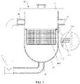
- FIG. 4 is a schematic structural diagram of a gravity filter 40 according to an embodiment of this application
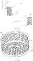
- FIG. 5 is a schematic structural diagram of a filter screen 44 according to an embodiment of this application.
- the gravity filter 40 includes a tank 43 and a filter screen 44 disposed inside the tank 43, a feed port 41 and a first discharge port 42 are both disposed on the tank 43, and a height of the filter screen 44 in the tank 43 is between a height of the feed port 41 and a height of the first discharge port 42.
- the filter screen 44 is configured to filter a slurry entering the gravity filter 40 from the feed port 41, so that a slurry filtered through the filter screen 44 by using gravity flows out from the first discharge port 42.
- the filter screen 44 is disposed inside the tank 43, and a height of the filter screen 44 on the tank 43 is between a height of the feed port 41 and a height of the first discharge port 42, so that the filter screen 44 can divide an internal space of the tank 43 into two parts: an unfiltered chamber and a filtered chamber.
- the unfiltered chamber communicates with the feed port 41
- the filtered chamber communicates with the first discharge port 42
- the unfiltered chamber communicates with the filtered chamber through filter holes in the filter screen 44.
- the filter screen 44 intercepts large-particle soft substances and hard particles whose particle sizes are larger than a hole diameter of the filter screen 44 in the slurry. Because the slurry flows inside the tank 43 under gravity, it is difficult for the large-particle soft substances in the slurry to enter the filtered chamber through the filter screen 44, so as to reduce a quantity of large-particle soft substances in the slurry.
- the filter screen 44 includes a bottom wall 441 and a side wall 442 disposed around the bottom wall 441.
- the side wall 442 and the bottom wall 441 enclose to form a collecting and filtering cavity with an opening at the top.
- Both the bottom wall 441 and the side wall 442 are provided with filter holes.
- the filter screen 44 may be a cylinder with an opening at the top.
- the filter screen 44 may be a cylindrical cylinder or a prismatic cylinder.
- the side wall 442 is disposed around an outer circumference of the bottom wall 441 and encloses the collecting and filtering cavity with an opening at the top, so that the opening of the filter screen 44 can communicate with the feed port 41, and the slurry flows into the collecting and filtering cavity from the feed port 41 to be filtered. Because both the side wall 442 and the bottom wall 441 of the filter screen 44 are provided with filter holes, both the side wall 442 and the bottom wall 441 of the filter screen 44 can filter the slurry. This can increase a filtering speed and a flow rate of the slurry and improve filtering efficiency.
- the filter screen 44 may alternatively be of a sheet structure.
- the filter screen 44 may be detachably connected to the inside of the tank 43. In this way, when the filter screen 44 is blocked, the filter screen 44 can be removed from the tank 43 for replacement or cleaning before recycling, thereby reducing use costs.
- the filter screen 44 may be made of stainless steel.
- an inner peripheral wall of the tank 43 is provided with a support convex portion 431.
- the support convex portion 431 is located between the side wall 442 and the inner peripheral wall of the tank 43.
- a flange 443 is further disposed on an outer side of the side wall 442 close to the opening of the collecting and filtering cavity, and the flange 443 abuts against the top of the support convex portion 431.
- the flange 443 is an outer flange that is disposed outside the top of the side wall 442 and protruding away from the collecting and filtering cavity.
- the support convex portion 431 may be a convex structure that is continuously disposed around a central axis of the tank 43 along the inner peripheral wall of the tank 43, or may be a convex structure that is spaced apart around the central axis of the tank 43 along the inner peripheral wall of the tank 43.
- the flange 443 on the filter screen 44 abuts against the support convex portion 431, so that the filter screen 44 can be nested in the tank 43. This manner facilitates disassembly and assembly. When the filter screen 44 is blocked, a user can easily remove the filter screen 44 from the tank 43 for replacement or cleaning.
- the filter screen 44 and the tank 43 may alternatively be connected and fixed to each other in another detachable manner.
- a clamping structure for mutual clamping is disposed between the inner peripheral wall of the tank 43 and the side wall 442.
- the tank 43 may be of a cylinder structure with an opening on the top, and the opening of the tank 43 is covered with an end cover 45.
- the end cover 45 is detachably connected to the tank 43, so that a user can open the end cover 45 and take out the filter screen 44 inside the tank 43 when necessary.
- the mesh number of the filter screen 44 is 20-70.
- the mesh number of the filter screen 44 may be 20, 30, 40, 50, 60, or 70.
- the tank 43 is further provided with a second discharge port 46.
- a lowest point of the second discharge port 46 in the tank 43 is located between the feed port 41 and the filter screen 44, and the first discharge port 42 communicates with the second feed port 41 outside the tank 43.
- the second discharge port 46 may alternatively be located at a same height as the feed port 41 on the side wall 442 of the tank 43, and the first discharge port 42 is disposed at the bottom of the tank 43, as long as it is ensured that a minimum height of the second discharge port 46 on the tank 43 is greater than the height of the filter screen 44 in the tank 43.
- the second discharge port 46 is applied when the slurry entering the tank 43 fails to be filtered through the filter screen 44 and then fails to completely flow out from the first discharge port 42 after the filter screen 44 is blocked. In this case, the slurry that has not been filtered by the filter screen 44 can be directly conveyed outward to the coating apparatus 10 through the second discharge port 46, so that the filtering apparatus can continuously provide the coating slurry to the coating apparatus 10.
- the slurry filtering apparatus 20 further includes a transfer tank 50 and a buffer tank 60.
- An outlet of the transfer tank 50 communicates with the feed port 41 of the tank 43.
- the rotating filter element 30 is located between the outlet of the transfer tank 50 and the feed port 41 of the tank 43.
- the transfer tank 50 is configured to provide a to-be-filtered slurry to the rotating filter element 30.
- An inlet of the buffer tank 60 communicates with the first discharge port 42, and the buffer tank 60 is configured to store a slurry filtered by the gravity filter 40. The filtered slurry is conveyed to the coating apparatus 10 through an outlet of the buffer tank 60.
- the gravity filter 40 further includes a three-way pipe 47. Two openings of the three-way pipe 47 communicate with the first discharge port 42 and the second discharge port 46 respectively, and the other discharge opening of the three-way pipe 47 communicates with the outlet of the transfer tank 50.
- the slurry filtering apparatus 20 further includes a secondary filter element 70.
- the secondary filter element 70 is connected to the outlet of the buffer tank, and a filtering particle size of the secondary filter element 70 is smaller than that of the rotating filter element 30. In other words, a diameter of a screen hole of the secondary filter element 70 is smaller than that of the rotating filter element 30.
- the secondary filter element 70 may be directly installed in a feeding pipeline that communicates with the discharge port of the gravity filter 40, or may be installed in a post filter that communicates with the discharge port of the gravity filter 40.
- the secondary filter element 70 is disposed at the outlet of the buffer tank, so that the secondary filter element 70 can further filter out particle impurities in the slurry that have not been filtered by the rotating filter element 30 and the gravity filter 40.
- the secondary filter element 70 may alternatively be disposed between the rotating filter element 30 and the feed port 41 of the gravity filter 40.
- the filtering particle size of the rotating filter element 30 is greater than 0.15 mm, and the filtering particle size of the secondary filter element 70 is greater than 0.075 mm.
- the diameter of the screen hole of the rotating filter element 30 is less than 0.15 mm and greater than 0.075 mm, and the diameter of the screen hole of the secondary filter element 70 is less than 0.075 mm.
Landscapes
- Chemical & Material Sciences (AREA)
- Chemical Kinetics & Catalysis (AREA)
- Engineering & Computer Science (AREA)
- Manufacturing & Machinery (AREA)
- Electrochemistry (AREA)
- General Chemical & Material Sciences (AREA)
- Battery Electrode And Active Subsutance (AREA)
- Coating Apparatus (AREA)
- Filtration Of Liquid (AREA)
Abstract
Description
- This application claims priority to
Chinese Patent Application No. 202120924138.6, filed on April 29, 2021 - Embodiments of this application relate to the field of lithium battery production technologies, and in particular, to a slurry filtering apparatus and a coating system.
- In a production process of a lithium battery, an electrode plate needs to be coated with a slurry. Coating quality affects the electrical performance and safety performance of the battery. Therefore, in a coating process, requirements for slurry conveying, slurry quality, and the like are relatively high. For example, the slurry cannot contain excessive impurities and large particles. However, because the slurry is in a conveying pipeline, with time passing by, the slurry easily deposits and agglomerates to form large-particle soft substances. Under a positive pressure, such large-particle soft substances easily penetrate a filter screen, resulting in scratches or fractures of the electrode plate during coating, and affecting coating quality.
- In view of the foregoing problem, embodiments of this application provide a slurry filtering apparatus and a coating system to reduce a quantity of large-particle soft substances formed by deposition and agglomeration in a slurry and improve coating quality.
- According to an aspect of the embodiments of this application, a slurry filtering apparatus is provided, including a rotating filter element and a gravity filter. The gravity filter is provided with a feed port and a first discharge port. A height of the feed port on the gravity filter is greater than that of the first discharge port on the gravity filter. The rotating filter element is connected to the feed port and is configured to provide a positive-pressure filtered slurry to the gravity filter. The first discharge port is configured to convey a slurry filtered by the gravity filter to a coating apparatus.
- In an optional manner, the gravity filter includes a tank and a filter screen disposed inside the tank. The feed port and the first discharge port are both disposed on the tank, and a height of the filter screen in the tank is between the height of the feed port and the height of the first discharge port.
- In an optional manner, the filter screen includes a bottom wall and a side wall disposed around the bottom wall. The side wall and the bottom wall enclose to form a collecting and filtering cavity with an opening at the top. Both the bottom wall and the side wall are provided with filter holes.
- In an optional manner, the filter screen is detachably disposed inside the tank.
- In an optional manner, an inner peripheral wall of the tank is provided with a support convex portion. The support convex portion is located between the side wall and the inner peripheral wall of the tank. A flange is further disposed on an outer side of the side wall close to the opening of the collecting and filtering cavity, and the flange abuts against the top of the support convex portion.
- In an optional manner, the mesh number of the filter screen is 20-70.
- In an optional manner, the tank is further provided with a second discharge port. A lowest point of the second discharge port on the tank is located between the feed port and the filter screen, and the second discharge port communicates with the first discharge port outside the tank.
- In an optional manner, the slurry filtering apparatus further includes a transfer tank and a buffer tank. An outlet of the transfer tank communicates with the feed port, and the rotating filter element is located between the outlet of the transfer tank and the feed port. The transfer tank is configured to provide a to-be-filtered slurry to the rotating filter element. An inlet of the buffer tank communicates with the first discharge port, the buffer tank is configured to store a slurry filtered by the gravity filter, and the filtered slurry is conveyed to the coating apparatus through an outlet of the buffer tank.
- In an optional manner, the slurry filtering apparatus further includes a secondary filter element. The secondary filter element is connected to the outlet of the buffer tank. A filtering particle size of the secondary filter element is smaller than that of the rotating filter element.
- In an optional manner, the filtering particle size of the rotating filter element is greater than 0.15 mm, and the filtering particle size of the secondary filter element is greater than 0.075 mm.
- According to another aspect of the embodiments of this application, a coating system is provided, including a coating apparatus and the foregoing slurry filtering apparatus. The slurry filtering apparatus is configured to provide a filtered coating slurry to the coating apparatus.
- In the embodiments of this application, the rotating filter element is connected to the feed port of the gravity filter. Because the height of the feed port of the gravity filter is greater than that of the first discharge port on the gravity filter, the slurry flows from top to bottom in the gravity filter due to gravity, and large-particle soft substances are not subject to excessive positive pressure and are difficult to penetrate the gravity filter. Therefore, the large-particle soft substances can be effectively intercepted by the gravity filter, and the gravity filter can provide a slurry with less impurities of large-particle soft substances to the coating apparatus from the first discharge port. This reduces a quantity of large-particle soft substances in the slurry and solves a problem that coating quality is affected by fractures, scratches, and the like of an electrode plate caused during coating due to existence of a large quantity of large-particle soft substances, thereby improving the coating quality.
- The above descriptions are merely an overview of the technical solutions of this application. To understand technical means of this application more clearly, the technical means may be implemented in accordance with content of this specification. To make the above and other purposes, features, and advantages of this application more comprehensible, the following implementations of this application are specifically given as examples.
- Other advantages and benefits become apparent to persons of ordinary skill in the art by reading detailed descriptions of the following preferred implementations. The accompanying drawings are merely intended to illustrate the preferred implementations and are not intended to limit this application. Throughout the accompanying drawings, same reference numerals represent same components. In the accompanying drawings:
-
FIG. 1 is a schematic structural diagram of a coating system according to an embodiment of this application; -
FIG. 2 is a schematic structural diagram of a coating apparatus according to an embodiment of this application; -
FIG. 3 is a schematic structural diagram of a slurry filtering apparatus according to an embodiment of this application; -
FIG. 4 is a schematic structural diagram of a gravity filter according to an embodiment of this application; and -
FIG. 5 is a schematic structural diagram of a filter screen according to an embodiment of this application. - Reference signs in descriptions of embodiments are as follows:
- 1. coating system; 10. coating apparatus; 11. coating extrusion head; 12. unwinding assembly; 13. drying assembly; 14. winding assembly; 20. slurry filtering apparatus; 30. rotating filter element;
- 40. gravity filter; 41. feed port; 42. first discharge port; 43. tank; 431. support convex portion; 44. filter screen; 441. bottom wall; 442. side wall; 443. flange; 45. end cover; 46. second discharge port; 47. three-way pipe;
- 50. transfer tank; 60. buffer tank; and 70. secondary filter element.
- The following describes in detail embodiments of technical solutions of this application with reference to accompanying drawings. The following embodiments are only used to more clearly describe the technical solutions of this application. Therefore, they are only used as examples and cannot be used to limit the scope of protection of this application.
- In a filtering process, with the time of being in a conveying pipeline passing by, a slurry easily forms large-particle soft substances by deposition and agglomeration. Currently, during slurry filtering, a slurry usually needs to be pushed by using a pump body or other power devices to pass through a filter element for filtering. In this positive-pressure filtering manner, large-particle soft substances easily penetrate the filter element under a positive pressure. As a result, a filtering apparatus cannot effectively perform filtering and interception. In this case, during coating, large-particle soft substances are coated on a surface of an electrode plate, resulting in particle scratches on the surface of the electrode plate or even fractures of the electrode plate.
- To solve the foregoing problem, the inventors redesigned and improved a structure of the existing filtering apparatus and found that a manner of first performing positive-pressure filtering on a slurry through a filter element and then performing filtering by using a gravity filtering apparatus can effectively filter out most of large-particle soft substances in the slurry to solve a problem that coating quality is affected due to large-particle soft substances.
- Referring to
FIG. 1 and FIG. 2, FIG. 1 is a schematic structural diagram of acoating system 1 according to an embodiment of this application, andFIG. 2 is a schematic structural diagram of acoating apparatus 10 according to an embodiment of this application. This embodiment of this application provides acoating system 1. Thecoating system 1 includes acoating apparatus 10 and aslurry filtering apparatus 20. Theslurry filtering apparatus 20 is configured to provide a filtered coating slurry to thecoating apparatus 10. Thecoating apparatus 10 may be a coating machine. The coating machine includes an extrusion head 11. The extrusion head 11 is configured to apply the slurry provided by theslurry filtering apparatus 20 on an electrode plate of a battery. - In some embodiments, the coating machine may further include an unwinding assembly 12, a drying
assembly 13, and a windingassembly 14. The unwinding assembly 12, the extrusion head 11, the dryingassembly 13, and the windingassembly 14 are sequentially disposed in a conveying direction of the electrode plate. The unwinding assembly 12 is configured to deliver the electrode plate to be coated with a slurry to the extrusion head 11, so that the extrusion head 11 can apply the slurry on the surface of the to-be-coated electrode plate. The dryingassembly 13 is configured to dry the electrode plate that has been coated with the slurry. The windingassembly 14 is configured to wind up the electrode plate that has been coated with slurry and dried. - In some embodiments, the coating machine may further include other components, for example, a control assembly (not shown in the figure), but no limitation is set thereto. The control assembly is electrically connected to all of the extrusion head 11, the unwinding assembly 12, the drying
assembly 13, and the windingassembly 14 to control and coordinate operations of all assemblies to coat the electrode plate. - Referring to
FIG. 3 andFIG. 1 ,FIG. 3 is a schematic structural diagram of aslurry filtering apparatus 20 according to an embodiment of this application. In some embodiments, theslurry filtering apparatus 20 includes arotating filter element 30 and agravity filter 40. Thegravity filter 40 is provided with afeed port 41 and afirst discharge port 42. A height of thefeed port 41 on thegravity filter 40 is greater than that of thefirst discharge port 42 on thegravity filter 40. Therotating filter element 30 is connected to thefeed port 41. Therotating filter element 30 is configured to provide a positive-pressure filtered slurry to thegravity filter 40. Thefirst discharge port 42 is configured to convey a slurry filtered by thegravity filter 40 to acoating apparatus 10. - The
rotating filter element 30 may be directly installed in a feed pipeline communicating with thefeed port 41 of thegravity filter 40, or may be installed in a prefilter communicating with thefeed port 41 of thegravity filter 40. - When the slurry flows into the
gravity filter 40 through therotating filter element 30, therotating filter element 30 can block hard particles in the slurry. However, under a push of a positive pressure, large-particle soft substances penetrate therotating filter element 30 and enters thegravity filter 40 from thefeed port 41. Because the height of thefeed port 41 of thegravity filter 40 is greater than that of thefirst discharge port 42 of thegravity filter 40, the slurry flows from top to bottom in thegravity filter 40 due to gravity, and large-particle soft substances are not subject to excessive positive pressure and are difficult to penetrate thegravity filter 40. Therefore, the large-particle soft substances can be intercepted by thegravity filter 40, and thegravity filter 40 can provide a slurry with less impurities of large-particle soft substances to thecoating apparatus 10 from thefirst discharge port 42. This reduces a quantity of large-particle soft substances in the slurry and solves a problem that coating quality is affected by fractures, scratches, and the like of an electrode plate caused during coating due to existence of a large quantity of large-particle soft substances, thereby improving the coating quality. - Referring to
FIG. 4 andFIG. 5 ,FIG. 4 is a schematic structural diagram of agravity filter 40 according to an embodiment of this application, andFIG. 5 is a schematic structural diagram of a filter screen 44 according to an embodiment of this application. In some embodiments, thegravity filter 40 includes atank 43 and a filter screen 44 disposed inside thetank 43, afeed port 41 and afirst discharge port 42 are both disposed on thetank 43, and a height of the filter screen 44 in thetank 43 is between a height of thefeed port 41 and a height of thefirst discharge port 42. - The filter screen 44 is configured to filter a slurry entering the
gravity filter 40 from thefeed port 41, so that a slurry filtered through the filter screen 44 by using gravity flows out from thefirst discharge port 42. - In this embodiment, the filter screen 44 is disposed inside the
tank 43, and a height of the filter screen 44 on thetank 43 is between a height of thefeed port 41 and a height of thefirst discharge port 42, so that the filter screen 44 can divide an internal space of thetank 43 into two parts: an unfiltered chamber and a filtered chamber. The unfiltered chamber communicates with thefeed port 41, the filtered chamber communicates with thefirst discharge port 42, and the unfiltered chamber communicates with the filtered chamber through filter holes in the filter screen 44. After the slurry enters the unfiltered chamber inside thetank 43 through thefeed port 41, the filter screen 44 intercepts large-particle soft substances and hard particles whose particle sizes are larger than a hole diameter of the filter screen 44 in the slurry. Because the slurry flows inside thetank 43 under gravity, it is difficult for the large-particle soft substances in the slurry to enter the filtered chamber through the filter screen 44, so as to reduce a quantity of large-particle soft substances in the slurry. - In some embodiments, the filter screen 44 includes a
bottom wall 441 and aside wall 442 disposed around thebottom wall 441. Theside wall 442 and thebottom wall 441 enclose to form a collecting and filtering cavity with an opening at the top. Both thebottom wall 441 and theside wall 442 are provided with filter holes. - The filter screen 44 may be a cylinder with an opening at the top. For example, the filter screen 44 may be a cylindrical cylinder or a prismatic cylinder.
- The
side wall 442 is disposed around an outer circumference of thebottom wall 441 and encloses the collecting and filtering cavity with an opening at the top, so that the opening of the filter screen 44 can communicate with thefeed port 41, and the slurry flows into the collecting and filtering cavity from thefeed port 41 to be filtered. Because both theside wall 442 and thebottom wall 441 of the filter screen 44 are provided with filter holes, both theside wall 442 and thebottom wall 441 of the filter screen 44 can filter the slurry. This can increase a filtering speed and a flow rate of the slurry and improve filtering efficiency. - It can be understood that in some other embodiments, the filter screen 44 may alternatively be of a sheet structure.
- In some embodiments, the filter screen 44 may be detachably connected to the inside of the
tank 43. In this way, when the filter screen 44 is blocked, the filter screen 44 can be removed from thetank 43 for replacement or cleaning before recycling, thereby reducing use costs. The filter screen 44 may be made of stainless steel. - In some embodiments, an inner peripheral wall of the
tank 43 is provided with a supportconvex portion 431. The supportconvex portion 431 is located between theside wall 442 and the inner peripheral wall of thetank 43. Aflange 443 is further disposed on an outer side of theside wall 442 close to the opening of the collecting and filtering cavity, and theflange 443 abuts against the top of the supportconvex portion 431. - The
flange 443 is an outer flange that is disposed outside the top of theside wall 442 and protruding away from the collecting and filtering cavity. The supportconvex portion 431 may be a convex structure that is continuously disposed around a central axis of thetank 43 along the inner peripheral wall of thetank 43, or may be a convex structure that is spaced apart around the central axis of thetank 43 along the inner peripheral wall of thetank 43. - In this embodiment, the
flange 443 on the filter screen 44 abuts against the supportconvex portion 431, so that the filter screen 44 can be nested in thetank 43. This manner facilitates disassembly and assembly. When the filter screen 44 is blocked, a user can easily remove the filter screen 44 from thetank 43 for replacement or cleaning. - In some other embodiments, the filter screen 44 and the
tank 43 may alternatively be connected and fixed to each other in another detachable manner. For example, a clamping structure for mutual clamping is disposed between the inner peripheral wall of thetank 43 and theside wall 442. - In some embodiments, the
tank 43 may be of a cylinder structure with an opening on the top, and the opening of thetank 43 is covered with anend cover 45. Theend cover 45 is detachably connected to thetank 43, so that a user can open theend cover 45 and take out the filter screen 44 inside thetank 43 when necessary. - In some embodiments, the mesh number of the filter screen 44 is 20-70. For example, the mesh number of the filter screen 44 may be 20, 30, 40, 50, 60, or 70.
- The larger the mesh number of the filter screen 44 is, the smaller a diameter of a filter hole and a particle size of particles that can be filtered are. The smaller the mesh number of the filter screen 44 is, the larger the hole diameter of the filter screen 44 and the particle size of the particles that can be filtered are. If the mesh number of the filter screen 44 is 20-70, the corresponding diameter of the filter hole of the filter screen 44 is 0.212-0.850 mm. That the diameter of the filter hole of the filter screen 44 falls within this mesh range not only ensures that hard particles and agglomerated particles whose particle sizes are larger than this range are intercepted by the filter screen 44, but also ensures that flow and a flow rate of the slurry can be sufficient for filtering. This avoids a coating quality problem caused by insufficient slurry supply during coating when the flow and the flow rate of the slurry for filtering become smaller due to an excessively small filtering particle size.
- Still referring to
FIG. 1 ,FIG. 4 , andFIG. 5 , in some embodiments, thetank 43 is further provided with asecond discharge port 46. A lowest point of thesecond discharge port 46 in thetank 43 is located between thefeed port 41 and the filter screen 44, and thefirst discharge port 42 communicates with thesecond feed port 41 outside thetank 43. - The
second discharge port 46 may alternatively be located at a same height as thefeed port 41 on theside wall 442 of thetank 43, and thefirst discharge port 42 is disposed at the bottom of thetank 43, as long as it is ensured that a minimum height of thesecond discharge port 46 on thetank 43 is greater than the height of the filter screen 44 in thetank 43. Thesecond discharge port 46 is applied when the slurry entering thetank 43 fails to be filtered through the filter screen 44 and then fails to completely flow out from thefirst discharge port 42 after the filter screen 44 is blocked. In this case, the slurry that has not been filtered by the filter screen 44 can be directly conveyed outward to thecoating apparatus 10 through thesecond discharge port 46, so that the filtering apparatus can continuously provide the coating slurry to thecoating apparatus 10. - In some embodiments, the
slurry filtering apparatus 20 further includes atransfer tank 50 and abuffer tank 60. An outlet of thetransfer tank 50 communicates with thefeed port 41 of thetank 43. Therotating filter element 30 is located between the outlet of thetransfer tank 50 and thefeed port 41 of thetank 43. Thetransfer tank 50 is configured to provide a to-be-filtered slurry to therotating filter element 30. An inlet of thebuffer tank 60 communicates with thefirst discharge port 42, and thebuffer tank 60 is configured to store a slurry filtered by thegravity filter 40. The filtered slurry is conveyed to thecoating apparatus 10 through an outlet of thebuffer tank 60. - Specifically, the
gravity filter 40 further includes a three-way pipe 47. Two openings of the three-way pipe 47 communicate with thefirst discharge port 42 and thesecond discharge port 46 respectively, and the other discharge opening of the three-way pipe 47 communicates with the outlet of thetransfer tank 50. - In some embodiments, the
slurry filtering apparatus 20 further includes asecondary filter element 70. Thesecondary filter element 70 is connected to the outlet of the buffer tank, and a filtering particle size of thesecondary filter element 70 is smaller than that of therotating filter element 30. In other words, a diameter of a screen hole of thesecondary filter element 70 is smaller than that of therotating filter element 30. Thesecondary filter element 70 may be directly installed in a feeding pipeline that communicates with the discharge port of thegravity filter 40, or may be installed in a post filter that communicates with the discharge port of thegravity filter 40. - In this embodiment, the
secondary filter element 70 is disposed at the outlet of the buffer tank, so that thesecondary filter element 70 can further filter out particle impurities in the slurry that have not been filtered by therotating filter element 30 and thegravity filter 40. - Certainly, in some other embodiments, the
secondary filter element 70 may alternatively be disposed between therotating filter element 30 and thefeed port 41 of thegravity filter 40. - In some embodiments, the filtering particle size of the
rotating filter element 30 is greater than 0.15 mm, and the filtering particle size of thesecondary filter element 70 is greater than 0.075 mm. In other words, the diameter of the screen hole of therotating filter element 30 is less than 0.15 mm and greater than 0.075 mm, and the diameter of the screen hole of thesecondary filter element 70 is less than 0.075 mm. When the hole diameters of therotating filter element 30 and thesecondary filter element 70 fall within this hole diameter range, after the slurry is filtered through therotating filter element 30 and thesecondary filter element 70, most of hard particle impurities can be filtered out, reducing impact of hard particles on coating quality. - It should be noted that, unless otherwise specified, the technical terms or scientific terms used in the embodiments of this application should have a general meaning understood by persons skilled in the art to which the embodiments of this application belong. In the descriptions of the embodiments of this application, orientations or position relationships indicated by the terms "height", "top", "bottom", "inside", "outside", and the like are based on orientations or position relationships shown in the accompanying drawings and are merely intended for ease of description of the embodiments of this application, rather than indicating or implying that an apparatus or a component needs to have a particular direction or needs to be constructed and operated in a particular orientation. Therefore, this shall not be construed as any limitation on the embodiments of this application. Finally, it should be noted that the above embodiments are merely intended for describing the technical solutions of this application, but not for limiting this application. Although this application is described in detail with reference to the above embodiments, persons of ordinary skill in the art should understand that they may still make modifications to the technical solutions described in the above embodiments or make equivalent replacements to some or all technical features thereof. These modifications or replacements do not make the essence of the corresponding technical solutions depart from the scope of the technical solutions of the embodiments of this application, and should all fall within the scope of the claims and this specification of this application. In particular, the technical features mentioned in the embodiments can be combined in any manner as long as there is no structural conflict. This application is not limited to the specific embodiments disclosed in this specification, but includes all technical solutions falling within the scope of the claims.
Claims (11)
- A slurry filtering apparatus (20), comprising:a rotating filter element (30); anda gravity filter (40), wherein the gravity filter (40) is provided with a feed port (41) and a first discharge port (42), a height of the feed port (41) on the gravity filter (40) is greater than that of the first discharge port (42) on the gravity filter (40), the rotating filter element (30) is connected to the feed port (41) and is configured to provide a positive-pressure filtered slurry to the gravity filter (40), and the first discharge port (42) is configured to convey a slurry filtered by the gravity filter (40) to a coating apparatus (10).
- The slurry filtering apparatus (20) according to claim 1, wherein the gravity filter (40) comprises a tank (43) and a filter screen (44) disposed inside the tank (43), the feed port (41) and the first discharge port (42) are both disposed on the tank (43), and a height of the filter screen (44) in the tank (43) is between the height of the feed port (41) and the height of the first discharge port (42).
- The slurry filtering apparatus (20) according to claim 2, wherein the filter screen (44) comprises a bottom wall (441) and a side wall (442) disposed around the bottom wall (441), the side wall (442) and the bottom wall (441) enclose to form a collecting and filtering cavity with an opening at the top, and both the bottom wall (441) and the side wall (442) are provided with filter holes.
- The slurry filtering apparatus (20) according to claim 3, wherein the filter screen (44) is detachably disposed inside the tank (43).
- The slurry filtering apparatus (20) according to claim 4, wherein an inner peripheral wall of the tank (43) is provided with a support convex portion (431), the support convex portion (431) is located between the side wall (442) and the inner peripheral wall of the tank (43), a flange (443) is further disposed on an outer side of the side wall (442) close to the opening of the collecting and filtering cavity, and the flange (443) abuts against the top of the support convex portion (431).
- The slurry filtering apparatus (20) according to any one of claims 2 to 5, wherein the mesh number of the filter screen (44) is 20-70.
- The slurry filtering apparatus (20) according to any one of claims 2 to 6, wherein the tank (43) is further provided with a second discharge port (46), a lowest point of the second discharge port (46) on the tank (43) is located between the feed port (41) and the filter screen (44), and the second discharge port (46) communicates with the first discharge port (42) outside the tank (43).
- The slurry filtering apparatus (20) according to any one of claims 1 to 7, wherein the slurry filtering apparatus (20) further comprises a transfer tank (50) and a buffer tank (60), an outlet of the transfer tank (50) communicates with the feed port (41), the rotating filter element (30) is located between the outlet of the transfer tank (50) and the feed port (41), the transfer tank (50) is configured to provide a to-be-filtered slurry to the rotating filter element (30), an inlet of the buffer tank (60) communicates with the first discharge port (42), the buffer tank (60) is configured to store a slurry filtered by the gravity filter (40), and the filtered slurry is conveyed to the coating apparatus (10) through an outlet of the buffer tank (60).
- The slurry filtering apparatus (20) according to claim 8, wherein the slurry filtering apparatus (20) further comprises a secondary filter element (70), the secondary filter element (70) is connected to the outlet of the buffer tank (60), and a filtering particle size of the secondary filter element (70) is smaller than that of the rotating filter element (30).
- The slurry filtering apparatus (20) according to claim 9, wherein the filtering particle size of the rotating filter element (30) is greater than 0.15 mm, and the filtering particle size of the secondary filter element (70) is greater than 0.075 mm.
- A coating system (1), comprising a coating apparatus (10) and the slurry filtering apparatus (20) according to any one of claims 1 to 10, wherein the slurry filtering apparatus (20) is configured to provide a filtered coating slurry to the coating apparatus (10).
Applications Claiming Priority (2)
| Application Number | Priority Date | Filing Date | Title |
|---|---|---|---|
| CN202120924138.6U CN215585615U (en) | 2021-04-29 | 2021-04-29 | Slurry filtering device and coating system |
| PCT/CN2022/081753 WO2022227925A1 (en) | 2021-04-29 | 2022-03-18 | Slurry filtering device and coating system |
Publications (4)
| Publication Number | Publication Date |
|---|---|
| EP4119213A1 true EP4119213A1 (en) | 2023-01-18 |
| EP4119213A8 EP4119213A8 (en) | 2023-03-22 |
| EP4119213A4 EP4119213A4 (en) | 2023-09-20 |
| EP4119213B1 EP4119213B1 (en) | 2025-12-24 |
Family
ID=79872630
Family Applications (1)
| Application Number | Title | Priority Date | Filing Date |
|---|---|---|---|
| EP22783414.0A Active EP4119213B1 (en) | 2021-04-29 | 2022-03-18 | Slurry filtering apparatus and coating system |
Country Status (7)
| Country | Link |
|---|---|
| US (1) | US12121833B2 (en) |
| EP (1) | EP4119213B1 (en) |
| JP (1) | JP7467671B2 (en) |
| KR (1) | KR102721770B1 (en) |
| CN (1) | CN215585615U (en) |
| ES (1) | ES3064676T3 (en) |
| WO (1) | WO2022227925A1 (en) |
Families Citing this family (5)
| Publication number | Priority date | Publication date | Assignee | Title |
|---|---|---|---|---|
| WO2022115918A1 (en) * | 2020-12-04 | 2022-06-09 | Rain Harvesting Pty Ltd | Tank screen |
| CN215585615U (en) | 2021-04-29 | 2022-01-21 | 宁德时代新能源科技股份有限公司 | Slurry filtering device and coating system |
| CN115715899B (en) * | 2022-12-23 | 2023-07-18 | 定州市福源食品有限公司 | Live pig slaughtering sewage treatment device |
| KR102763847B1 (en) * | 2023-03-31 | 2025-02-07 | 주식회사 원익피앤이 | Slurry Supply Device |
| CN120115335B (en) * | 2025-05-13 | 2025-08-19 | 江苏三旗流体设备有限公司 | Oil tank for spraying machine |
Family Cites Families (85)
| Publication number | Priority date | Publication date | Assignee | Title |
|---|---|---|---|---|
| US511798A (en) * | 1894-01-02 | rankine | ||
| US483847A (en) * | 1892-10-04 | Ooqoqoxoooooooooooooooooo | ||
| US281336A (en) * | 1883-07-17 | Walter m | ||
| US1367946A (en) * | 1921-02-08 | Continttotjs sugar-washing machine | ||
| US502583A (en) * | 1893-08-01 | rankine | ||
| US540810A (en) * | 1895-06-11 | And john h | ||
| US554206A (en) * | 1896-02-04 | Logel | ||
| US1253162A (en) * | 1915-09-01 | 1918-01-08 | Henry B Faber | Thickener. |
| US1192948A (en) * | 1915-11-17 | 1916-08-01 | William F Smith | Combined liquid conveyer and filter. |
| US1677503A (en) * | 1920-01-22 | 1928-07-17 | Ernest J Sweetland | Filter |
| US1577584A (en) * | 1921-07-26 | 1926-03-23 | Miller Mfg Co | Apparatus for separating trash from washing solutions |
| US1456883A (en) * | 1922-04-14 | 1923-05-29 | Deeks Hugh Allen | Gasoline filter |
| US1667465A (en) * | 1925-03-10 | 1928-04-24 | Justin F Wait | Filter and filtering method |
| US1843242A (en) * | 1929-04-08 | 1932-02-02 | Rafton Engineering Corp | Strainer system |
| US2073026A (en) * | 1932-03-04 | 1937-03-09 | Sf Bowser & Co Inc | Liquid purifying apparatus and process |
| US2185408A (en) * | 1936-10-14 | 1940-01-02 | Chemical Seed Treating Und Del | Seed treating machine |
| US2294179A (en) * | 1938-10-18 | 1942-08-25 | Hawley Engineering Corp | Method for screening burdened fluids |
| US2626709A (en) * | 1948-06-04 | 1953-01-27 | Selas Corp Of America | Liquid separator |
| US2548541A (en) * | 1948-07-08 | 1951-04-10 | Jessie L Macdonald | Hair trap for washbasins |
| US2697523A (en) * | 1951-12-08 | 1954-12-21 | Bloksma Romke | Filter with valved sediment trap |
| US2746607A (en) * | 1952-05-16 | 1956-05-22 | Selas Corp Of America | Porous membrane |
| US3347379A (en) * | 1965-04-12 | 1967-10-17 | Ex Cell O Corp | Filtration apparatus |
| US3369669A (en) * | 1966-02-09 | 1968-02-20 | Clifford W. Loftin | Domestic back flush water system filter |
| US3502213A (en) * | 1967-04-15 | 1970-03-24 | Sadatomo Kuribayashi | Strainer |
| SE346068B (en) * | 1969-04-24 | 1972-06-26 | Ingenioers Fa Vvs Utrustning A | |
| CH532409A (en) * | 1970-09-04 | 1973-01-15 | Doucet Charles | Method of filtering a fluid and filter for the implementation of this method |
| US3709329A (en) * | 1971-09-30 | 1973-01-09 | Smith Kline French Lab | Tablet classification machine |
| US3705649A (en) * | 1972-03-30 | 1972-12-12 | Kostas Savas Arvanitakis | Desludger apparatus and process |
| US3705648A (en) * | 1972-03-30 | 1972-12-12 | Kostas Savas Arvanitakis | Filtration system |
| CA1022857A (en) * | 1972-06-22 | 1977-12-20 | Hydrocyclonics Corporation | Rotary screen filter with continuous cleaning |
| US3979289A (en) * | 1972-11-08 | 1976-09-07 | Water Pollution Control Corporation | Filtration method |
| US3896005A (en) * | 1973-09-13 | 1975-07-22 | Hector M Zuccolotto | Filtering and debris removing apparatus for cleaning a sea water stream |
| US4198299A (en) * | 1973-12-26 | 1980-04-15 | Water Pollution Control Corporation | Microscreen method and apparatus |
| US3890236A (en) * | 1974-01-14 | 1975-06-17 | Water Inc Ag | Filter structure |
| SE408527B (en) * | 1975-01-28 | 1979-06-18 | Wennberg Ab C J | PROCEDURE AND DEVICE FOR REGENERATION OF PRESSURE FILTER |
| JPS51119168A (en) * | 1975-04-11 | 1976-10-19 | Iida Kosaku | Floating matter filtration-and treatment apparatus |
| US4062776A (en) * | 1976-07-07 | 1977-12-13 | Arie Blok | Sludge concentrator and conditioner |
| US4115271A (en) * | 1976-09-29 | 1978-09-19 | The Carborundum Company | Rotary drum screen |
| US4069979A (en) * | 1976-11-12 | 1978-01-24 | Yamamura Glass Kabushiki Kaisha | Method and apparatus for breaking up and separating waste glass to obtain cullet |
| US4140629A (en) * | 1977-09-15 | 1979-02-20 | Martco, Inc. | Conical screen separator |
| AT368781B (en) * | 1979-05-21 | 1982-11-10 | Escher Wyss Gmbh | SCREENING DEVICE FOR FIBER FIBER SUSPENSIONS, e.g. PAPER FIBER FIBER, WITH A ROTATING ROUND SCREEN |
| US4392421A (en) * | 1980-03-27 | 1983-07-12 | Seirei Industry Company Limited | Rice hulling and sorting device |
| US4424125A (en) * | 1981-12-14 | 1984-01-03 | Axis Products Limited | Separator apparatus |
| US4507202A (en) * | 1982-01-18 | 1985-03-26 | Dan Nord | Device for the separation of a liquid |
| ES8600011A1 (en) * | 1984-10-24 | 1985-10-16 | Metalquimia Sa | Filtration apparatus for use with a meat-piece fluid injector |
| DE3766831D1 (en) * | 1986-10-29 | 1991-01-31 | Josef Dipl Ing Merai | METHOD FOR DRAINING WASTEWATER SLUDGE AND SYSTEM FOR IMPLEMENTING THE METHOD. |
| US4966718A (en) * | 1986-11-26 | 1990-10-30 | Johnson Willard L | Cross flow filter method |
| US4857180A (en) * | 1988-02-26 | 1989-08-15 | Beloit Corporation | Rotating disc screen |
| US5114596A (en) * | 1990-10-16 | 1992-05-19 | The Graver Company | Backwash method and apparatus |
| US5133860A (en) * | 1991-12-31 | 1992-07-28 | Tai Liang C | Solid and liquid separator with a liquid filter |
| US5480547A (en) * | 1994-03-08 | 1996-01-02 | Pall Corporation | Corrosive liquid coalescer |
| EP0777517A1 (en) * | 1994-08-17 | 1997-06-11 | Pall Corporation | Method and apparatus for filtering edible oils |
| US5507396A (en) * | 1994-11-29 | 1996-04-16 | Carter Day International, Inc. | Rotating sizer with screen panels |
| US6227379B1 (en) * | 1994-12-14 | 2001-05-08 | Nth, Inc. | Rotary separator apparatus and method |
| EP0876302B1 (en) * | 1995-12-19 | 2000-07-26 | Biorem AG | Fat and oil removal installation |
| KR100544107B1 (en) * | 1999-01-22 | 2006-01-23 | 삼성에스디아이 주식회사 | Secondary battery electrode manufacturing device |
| US6305552B1 (en) * | 1999-03-12 | 2001-10-23 | Universal Leaf Tobacco Company, Inc. | Apparatus for removing matter from tobacco stems |
| SE514311C2 (en) * | 1999-05-03 | 2001-02-05 | Hyosong Lee | Method and apparatus for filtering particles from a liquid |
| DE10026344A1 (en) * | 2000-04-01 | 2001-10-04 | Membraflow Gmbh & Co Kg Filter | Filter module |
| DE10022538C2 (en) * | 2000-05-09 | 2002-05-29 | Wmf Wuerttemberg Metallwaren | Method and device for separating beverage substitutes |
| US6908545B2 (en) * | 2002-08-08 | 2005-06-21 | Pti Technologies, Inc. | Hydraulic filter assembly with priority valve |
| FI118374B (en) * | 2002-08-28 | 2007-10-31 | Steris Europe Inc | Process and apparatus for producing purified steam |
| UY28077A1 (en) * | 2002-11-12 | 2004-06-30 | Safe Food Corp Una Corporacion | APPLICATION SYSTEM WITH RECYCLING AND ITS RELATED USE OF AN ANTIMICROBIAL QUARTER AMMONIUM COMPOUND |
| US6884360B2 (en) * | 2003-07-03 | 2005-04-26 | Sei-Chang Chang | Filtration device with cross-flow function and its filtration method |
| US8211319B2 (en) * | 2003-09-16 | 2012-07-03 | Bp Corporation North America Inc. | Solid-liquid separation process |
| US7001515B2 (en) * | 2003-10-14 | 2006-02-21 | Townsend Engineering Company | Dual filter system for filtering of injector fluids |
| EP1911892B1 (en) * | 2006-10-12 | 2009-06-17 | Graf Plastics GmbH | Downpipe filter |
| WO2009087750A1 (en) * | 2008-01-04 | 2009-07-16 | Freund Corporation | Filter cleaning apparatus and method of cleaning filter |
| CN102481498B (en) | 2009-08-25 | 2014-11-05 | Smc株式会社 | Filter |
| JP2011115732A (en) * | 2009-12-04 | 2011-06-16 | Toyota Motor Corp | Coating liquid supply apparatus and filter line switching method |
| JP5386408B2 (en) * | 2010-03-03 | 2014-01-15 | 三菱重工業株式会社 | Electrode manufacturing equipment |
| KR101035150B1 (en) | 2011-04-07 | 2011-05-17 | 윤상진 | Slurry and Resource Recycling Filtration Drying Unit |
| FI20115350A0 (en) * | 2011-04-12 | 2011-04-12 | Steris Europe Inc | A device for separating a solid from a biowaste suspension |
| CN202136842U (en) | 2011-06-08 | 2012-02-08 | 天津力神电池股份有限公司 | Battery slurry filtering system |
| CN204637720U (en) * | 2015-05-19 | 2015-09-16 | 山东精工电子科技有限公司 | A kind of super capacitor slurry filtration system |
| CN204841199U (en) * | 2015-06-30 | 2015-12-09 | 山东精工电子科技有限公司 | Quick filtration system of ultracapacitor system thick liquids |
| CN105771381B (en) * | 2016-03-05 | 2017-12-12 | 杭州骄航环保科技有限公司 | Riverway sludge filter |
| EP3806975B1 (en) * | 2018-06-13 | 2024-12-04 | Cargill, Incorporated | A filtration process |
| SE542326C2 (en) * | 2018-06-21 | 2020-04-14 | Valmet Oy | Vacuum filter |
| US12036485B1 (en) * | 2019-07-16 | 2024-07-16 | Green Vault Systems, LLC | Continuous flow cold water extraction |
| CN111916656B (en) * | 2020-07-21 | 2025-05-13 | 合肥通用机械研究院有限公司 | An integrated production system for ternary materials |
| CN212998653U (en) * | 2020-08-24 | 2021-04-20 | 河南福森新能源科技有限公司 | Coating slurry filtering device |
| CN112170125A (en) | 2020-10-09 | 2021-01-05 | 昆山聚创新能源科技有限公司 | Automatic slurry conveying system of battery coating machine |
| CN112520897A (en) * | 2020-12-03 | 2021-03-19 | 无棣县华龙食品有限公司 | Environment-friendly sewage treatment plant is used in jujube goods production |
| CN215585615U (en) * | 2021-04-29 | 2022-01-21 | 宁德时代新能源科技股份有限公司 | Slurry filtering device and coating system |
-
2021
- 2021-04-29 CN CN202120924138.6U patent/CN215585615U/en active Active
-
2022
- 2022-03-18 JP JP2022558518A patent/JP7467671B2/en active Active
- 2022-03-18 EP EP22783414.0A patent/EP4119213B1/en active Active
- 2022-03-18 ES ES22783414T patent/ES3064676T3/en active Active
- 2022-03-18 WO PCT/CN2022/081753 patent/WO2022227925A1/en not_active Ceased
- 2022-03-18 KR KR1020227033897A patent/KR102721770B1/en active Active
-
2023
- 2023-04-11 US US18/298,392 patent/US12121833B2/en active Active
Also Published As
| Publication number | Publication date |
|---|---|
| JP2023526885A (en) | 2023-06-26 |
| EP4119213A8 (en) | 2023-03-22 |
| ES3064676T3 (en) | 2026-04-28 |
| EP4119213B1 (en) | 2025-12-24 |
| JP7467671B2 (en) | 2024-04-15 |
| KR102721770B1 (en) | 2024-10-23 |
| US20230249105A1 (en) | 2023-08-10 |
| KR20220149720A (en) | 2022-11-08 |
| CN215585615U (en) | 2022-01-21 |
| US12121833B2 (en) | 2024-10-22 |
| WO2022227925A1 (en) | 2022-11-03 |
| EP4119213A4 (en) | 2023-09-20 |
Similar Documents
| Publication | Publication Date | Title |
|---|---|---|
| EP4119213A1 (en) | Slurry filtering device and coating system | |
| CN112170125A (en) | Automatic slurry conveying system of battery coating machine | |
| CN211987435U (en) | Lithium battery slurry filtering device with two layers of relatively rotating filter screens | |
| CN206974792U (en) | Phytoplankton filters enrichment facility | |
| CN212998653U (en) | Coating slurry filtering device | |
| CN218833688U (en) | Sealed filter assembly | |
| CN214039061U (en) | Separator | |
| CN210058644U (en) | Prevent whirlwind dust collector and whirlwind dust pelletizing system of backmixing | |
| CN209575922U (en) | Filter element and battery coating system | |
| CN222384307U (en) | Basket filter | |
| CN213725164U (en) | Single-cylinder filter and material processing device | |
| CN220370487U (en) | Slurry buffer tank device capable of removing bubbles and pole piece production equipment | |
| CN210186672U (en) | Dust collecting device and weightlessness scale | |
| CN219333569U (en) | Filtration device and pulping machine | |
| CN213643649U (en) | Gas dehumidifier | |
| CN105526750A (en) | Liquid separator | |
| CN216572069U (en) | Novel particle filtering device | |
| CN218501377U (en) | Structure is prevented blockking up by self-cleaning structure pump valve | |
| CN208718895U (en) | A kind of air cleaner of the replaceable filter disc of air compressor machine | |
| CN109045787B (en) | Device and system for purifying pressure-sensitive glue | |
| CN213557679U (en) | Lithium battery slurry deironing filter equipment | |
| CN217746257U (en) | Air inlet filtering device of water storage container | |
| CN222694130U (en) | A filter device for a water-based paint loading cylinder | |
| CN210905394U (en) | Winnowing automatic separation dust removal system | |
| CN219963958U (en) | Anti-blocking nozzle for slurry spray drying |
Legal Events
| Date | Code | Title | Description |
|---|---|---|---|
| STAA | Information on the status of an ep patent application or granted ep patent |
Free format text: STATUS: UNKNOWN |
|
| STAA | Information on the status of an ep patent application or granted ep patent |
Free format text: STATUS: THE INTERNATIONAL PUBLICATION HAS BEEN MADE |
|
| PUAI | Public reference made under article 153(3) epc to a published international application that has entered the european phase |
Free format text: ORIGINAL CODE: 0009012 |
|
| STAA | Information on the status of an ep patent application or granted ep patent |
Free format text: STATUS: REQUEST FOR EXAMINATION WAS MADE |
|
| 17P | Request for examination filed |
Effective date: 20221014 |
|
| AK | Designated contracting states |
Kind code of ref document: A1 Designated state(s): AL AT BE BG CH CY CZ DE DK EE ES FI FR GB GR HR HU IE IS IT LI LT LU LV MC MK MT NL NO PL PT RO RS SE SI SK SM TR |
|
| RIN1 | Information on inventor provided before grant (corrected) |
Inventor name: DOU, JIANXIN Inventor name: WEN, YUQIAN Inventor name: HUANG, BIAO Inventor name: YAN, SHENGYUN Inventor name: GUO, ZHENGSHAN |
|
| A4 | Supplementary search report drawn up and despatched |
Effective date: 20230818 |
|
| RIC1 | Information provided on ipc code assigned before grant |
Ipc: B01D 29/96 20060101ALI20230811BHEP Ipc: B01D 35/00 20060101ALI20230811BHEP Ipc: B01D 29/35 20060101AFI20230811BHEP |
|
| STAA | Information on the status of an ep patent application or granted ep patent |
Free format text: STATUS: EXAMINATION IS IN PROGRESS |
|
| 17Q | First examination report despatched |
Effective date: 20240410 |
|
| DAV | Request for validation of the european patent (deleted) | ||
| DAX | Request for extension of the european patent (deleted) | ||
| RAP1 | Party data changed (applicant data changed or rights of an application transferred) |
Owner name: CONTEMPORARY AMPEREX TECHNOLOGY(HONG KONG) LIMITED |
|
| GRAP | Despatch of communication of intention to grant a patent |
Free format text: ORIGINAL CODE: EPIDOSNIGR1 |
|
| STAA | Information on the status of an ep patent application or granted ep patent |
Free format text: STATUS: GRANT OF PATENT IS INTENDED |
|
| INTG | Intention to grant announced |
Effective date: 20250922 |
|
| GRAS | Grant fee paid |
Free format text: ORIGINAL CODE: EPIDOSNIGR3 |
|
| GRAA | (expected) grant |
Free format text: ORIGINAL CODE: 0009210 |
|
| STAA | Information on the status of an ep patent application or granted ep patent |
Free format text: STATUS: THE PATENT HAS BEEN GRANTED |
|
| AK | Designated contracting states |
Kind code of ref document: B1 Designated state(s): AL AT BE BG CH CY CZ DE DK EE ES FI FR GB GR HR HU IE IS IT LI LT LU LV MC MK MT NL NO PL PT RO RS SE SI SK SM TR |
|
| REG | Reference to a national code |
Ref country code: CH Ref legal event code: F10 Free format text: ST27 STATUS EVENT CODE: U-0-0-F10-F00 (AS PROVIDED BY THE NATIONAL OFFICE) Effective date: 20251224 Ref country code: GB Ref legal event code: FG4D |
|
| REG | Reference to a national code |
Ref country code: DE Ref legal event code: R096 Ref document number: 602022027503 Country of ref document: DE |
|
| PGFP | Annual fee paid to national office [announced via postgrant information from national office to epo] |
Ref country code: GB Payment date: 20260325 Year of fee payment: 5 |
|
| REG | Reference to a national code |
Ref country code: LT Ref legal event code: MG9D |
|
| PG25 | Lapsed in a contracting state [announced via postgrant information from national office to epo] |
Ref country code: NO Free format text: LAPSE BECAUSE OF FAILURE TO SUBMIT A TRANSLATION OF THE DESCRIPTION OR TO PAY THE FEE WITHIN THE PRESCRIBED TIME-LIMIT Effective date: 20260324 |
|
| PGFP | Annual fee paid to national office [announced via postgrant information from national office to epo] |
Ref country code: DE Payment date: 20260324 Year of fee payment: 5 |
|
| PG25 | Lapsed in a contracting state [announced via postgrant information from national office to epo] |
Ref country code: FI Free format text: LAPSE BECAUSE OF FAILURE TO SUBMIT A TRANSLATION OF THE DESCRIPTION OR TO PAY THE FEE WITHIN THE PRESCRIBED TIME-LIMIT Effective date: 20251224 Ref country code: HR Free format text: LAPSE BECAUSE OF FAILURE TO SUBMIT A TRANSLATION OF THE DESCRIPTION OR TO PAY THE FEE WITHIN THE PRESCRIBED TIME-LIMIT Effective date: 20251224 |
|
| PGFP | Annual fee paid to national office [announced via postgrant information from national office to epo] |
Ref country code: AT Payment date: 20260301 Year of fee payment: 5 |
|
| PG25 | Lapsed in a contracting state [announced via postgrant information from national office to epo] |
Ref country code: RS Free format text: LAPSE BECAUSE OF FAILURE TO SUBMIT A TRANSLATION OF THE DESCRIPTION OR TO PAY THE FEE WITHIN THE PRESCRIBED TIME-LIMIT Effective date: 20260324 |
|
| PGFP | Annual fee paid to national office [announced via postgrant information from national office to epo] |
Ref country code: FR Payment date: 20260330 Year of fee payment: 5 |
|
| PG25 | Lapsed in a contracting state [announced via postgrant information from national office to epo] |
Ref country code: LV Free format text: LAPSE BECAUSE OF FAILURE TO SUBMIT A TRANSLATION OF THE DESCRIPTION OR TO PAY THE FEE WITHIN THE PRESCRIBED TIME-LIMIT Effective date: 20251224 |
|
| REG | Reference to a national code |
Ref country code: ES Ref legal event code: FG2A Ref document number: 3064676 Country of ref document: ES Kind code of ref document: T3 Effective date: 20260428 |