EP0876302B1 - Fat and oil removal installation - Google Patents
Fat and oil removal installation Download PDFInfo
- Publication number
- EP0876302B1 EP0876302B1 EP19960942222 EP96942222A EP0876302B1 EP 0876302 B1 EP0876302 B1 EP 0876302B1 EP 19960942222 EP19960942222 EP 19960942222 EP 96942222 A EP96942222 A EP 96942222A EP 0876302 B1 EP0876302 B1 EP 0876302B1
- Authority
- EP
- European Patent Office
- Prior art keywords
- container
- container chamber
- fat
- oil
- pipe
- Prior art date
- Legal status (The legal status is an assumption and is not a legal conclusion. Google has not performed a legal analysis and makes no representation as to the accuracy of the status listed.)
- Expired - Lifetime
Links
- 238000009434 installation Methods 0.000 title claims abstract 13
- 239000003925 fat Substances 0.000 claims abstract description 106
- 239000003921 oil Substances 0.000 claims abstract description 83
- 244000005700 microbiome Species 0.000 claims abstract description 41
- 239000002351 wastewater Substances 0.000 claims abstract description 37
- 239000004033 plastic Substances 0.000 claims abstract description 18
- 229920003023 plastic Polymers 0.000 claims abstract description 18
- 241000235015 Yarrowia lipolytica Species 0.000 claims abstract description 17
- 239000007788 liquid Substances 0.000 claims abstract description 16
- IJGRMHOSHXDMSA-UHFFFAOYSA-N Atomic nitrogen Chemical compound N#N IJGRMHOSHXDMSA-UHFFFAOYSA-N 0.000 claims abstract description 14
- 240000004808 Saccharomyces cerevisiae Species 0.000 claims abstract description 12
- 239000000463 material Substances 0.000 claims abstract description 12
- 238000000926 separation method Methods 0.000 claims abstract description 11
- 235000015097 nutrients Nutrition 0.000 claims abstract description 8
- 229910052757 nitrogen Inorganic materials 0.000 claims abstract description 7
- 229920000728 polyester Polymers 0.000 claims abstract description 3
- 238000005192 partition Methods 0.000 claims description 20
- 239000012876 carrier material Substances 0.000 claims description 14
- 239000007787 solid Substances 0.000 claims description 7
- QVGXLLKOCUKJST-UHFFFAOYSA-N atomic oxygen Chemical compound [O] QVGXLLKOCUKJST-UHFFFAOYSA-N 0.000 claims description 6
- 239000001301 oxygen Substances 0.000 claims description 6
- 229910052760 oxygen Inorganic materials 0.000 claims description 6
- 239000010802 sludge Substances 0.000 claims description 5
- 239000003570 air Substances 0.000 claims 1
- 230000005611 electricity Effects 0.000 claims 1
- 230000001105 regulatory effect Effects 0.000 claims 1
- 230000000630 rising effect Effects 0.000 claims 1
- 235000019198 oils Nutrition 0.000 description 75
- 239000004519 grease Substances 0.000 description 25
- XLYOFNOQVPJJNP-UHFFFAOYSA-N water Substances O XLYOFNOQVPJJNP-UHFFFAOYSA-N 0.000 description 20
- 241000196324 Embryophyta Species 0.000 description 19
- KRKNYBCHXYNGOX-UHFFFAOYSA-N citric acid Chemical compound OC(=O)CC(O)(C(O)=O)CC(O)=O KRKNYBCHXYNGOX-UHFFFAOYSA-N 0.000 description 18
- 230000002906 microbiologic effect Effects 0.000 description 9
- 235000014593 oils and fats Nutrition 0.000 description 9
- 238000006065 biodegradation reaction Methods 0.000 description 7
- 230000000694 effects Effects 0.000 description 7
- 239000000126 substance Substances 0.000 description 7
- 108090001060 Lipase Proteins 0.000 description 6
- 238000006731 degradation reaction Methods 0.000 description 6
- 230000002366 lipolytic effect Effects 0.000 description 6
- -1 polypropylene Polymers 0.000 description 6
- 102000004882 Lipase Human genes 0.000 description 5
- 239000004367 Lipase Substances 0.000 description 5
- 230000015556 catabolic process Effects 0.000 description 5
- 235000013305 food Nutrition 0.000 description 5
- 235000019421 lipase Nutrition 0.000 description 5
- 235000012054 meals Nutrition 0.000 description 5
- 239000002245 particle Substances 0.000 description 5
- 239000004743 Polypropylene Substances 0.000 description 4
- 229920001155 polypropylene Polymers 0.000 description 4
- 239000000047 product Substances 0.000 description 4
- WRIDQFICGBMAFQ-UHFFFAOYSA-N (E)-8-Octadecenoic acid Natural products CCCCCCCCCC=CCCCCCCC(O)=O WRIDQFICGBMAFQ-UHFFFAOYSA-N 0.000 description 3
- LQJBNNIYVWPHFW-UHFFFAOYSA-N 20:1omega9c fatty acid Natural products CCCCCCCCCCC=CCCCCCCCC(O)=O LQJBNNIYVWPHFW-UHFFFAOYSA-N 0.000 description 3
- QSBYPNXLFMSGKH-UHFFFAOYSA-N 9-Heptadecensaeure Natural products CCCCCCCC=CCCCCCCCC(O)=O QSBYPNXLFMSGKH-UHFFFAOYSA-N 0.000 description 3
- 229910000669 Chrome steel Inorganic materials 0.000 description 3
- 102000004190 Enzymes Human genes 0.000 description 3
- 108090000790 Enzymes Proteins 0.000 description 3
- 239000005642 Oleic acid Substances 0.000 description 3
- ZQPPMHVWECSIRJ-UHFFFAOYSA-N Oleic acid Natural products CCCCCCCCC=CCCCCCCCC(O)=O ZQPPMHVWECSIRJ-UHFFFAOYSA-N 0.000 description 3
- 229920006328 Styrofoam Polymers 0.000 description 3
- 239000000969 carrier Substances 0.000 description 3
- 230000000593 degrading effect Effects 0.000 description 3
- 235000014113 dietary fatty acids Nutrition 0.000 description 3
- 229930195729 fatty acid Natural products 0.000 description 3
- 239000000194 fatty acid Substances 0.000 description 3
- 150000004665 fatty acids Chemical class 0.000 description 3
- 238000010438 heat treatment Methods 0.000 description 3
- QXJSBBXBKPUZAA-UHFFFAOYSA-N isooleic acid Natural products CCCCCCCC=CCCCCCCCCC(O)=O QXJSBBXBKPUZAA-UHFFFAOYSA-N 0.000 description 3
- 238000012423 maintenance Methods 0.000 description 3
- 230000002503 metabolic effect Effects 0.000 description 3
- 239000002207 metabolite Substances 0.000 description 3
- 238000000034 method Methods 0.000 description 3
- ZQPPMHVWECSIRJ-KTKRTIGZSA-N oleic acid Chemical compound CCCCCCCC\C=C/CCCCCCCC(O)=O ZQPPMHVWECSIRJ-KTKRTIGZSA-N 0.000 description 3
- 238000002360 preparation method Methods 0.000 description 3
- 239000010865 sewage Substances 0.000 description 3
- 230000035943 smell Effects 0.000 description 3
- 239000008261 styrofoam Substances 0.000 description 3
- 230000035899 viability Effects 0.000 description 3
- 239000002028 Biomass Substances 0.000 description 2
- OKTJSMMVPCPJKN-UHFFFAOYSA-N Carbon Chemical compound [C] OKTJSMMVPCPJKN-UHFFFAOYSA-N 0.000 description 2
- CURLTUGMZLYLDI-UHFFFAOYSA-N Carbon dioxide Chemical compound O=C=O CURLTUGMZLYLDI-UHFFFAOYSA-N 0.000 description 2
- KDXKERNSBIXSRK-YFKPBYRVSA-N L-lysine Chemical compound NCCCC[C@H](N)C(O)=O KDXKERNSBIXSRK-YFKPBYRVSA-N 0.000 description 2
- 239000002253 acid Substances 0.000 description 2
- 230000015572 biosynthetic process Effects 0.000 description 2
- 229910052799 carbon Inorganic materials 0.000 description 2
- 238000005260 corrosion Methods 0.000 description 2
- 230000007797 corrosion Effects 0.000 description 2
- 230000001419 dependent effect Effects 0.000 description 2
- 239000000839 emulsion Substances 0.000 description 2
- 239000007789 gas Substances 0.000 description 2
- 230000005484 gravity Effects 0.000 description 2
- 230000001766 physiological effect Effects 0.000 description 2
- 230000002441 reversible effect Effects 0.000 description 2
- 238000003756 stirring Methods 0.000 description 2
- 238000004065 wastewater treatment Methods 0.000 description 2
- OWEGMIWEEQEYGQ-UHFFFAOYSA-N 100676-05-9 Natural products OC1C(O)C(O)C(CO)OC1OCC1C(O)C(O)C(O)C(OC2C(OC(O)C(O)C2O)CO)O1 OWEGMIWEEQEYGQ-UHFFFAOYSA-N 0.000 description 1
- 125000005477 2-oxoglutaric acid group Chemical group 0.000 description 1
- 240000000073 Achillea millefolium Species 0.000 description 1
- 235000007754 Achillea millefolium Nutrition 0.000 description 1
- GUBGYTABKSRVRQ-XLOQQCSPSA-N Alpha-Lactose Chemical compound O[C@@H]1[C@@H](O)[C@@H](O)[C@@H](CO)O[C@H]1O[C@@H]1[C@@H](CO)O[C@H](O)[C@H](O)[C@H]1O GUBGYTABKSRVRQ-XLOQQCSPSA-N 0.000 description 1
- KRKNYBCHXYNGOX-UHFFFAOYSA-K Citrate Chemical compound [O-]C(=O)CC(O)(CC([O-])=O)C([O-])=O KRKNYBCHXYNGOX-UHFFFAOYSA-K 0.000 description 1
- ODBLHEXUDAPZAU-ZAFYKAAXSA-N D-threo-isocitric acid Chemical compound OC(=O)[C@H](O)[C@@H](C(O)=O)CC(O)=O ODBLHEXUDAPZAU-ZAFYKAAXSA-N 0.000 description 1
- 102100031375 Endothelial lipase Human genes 0.000 description 1
- 239000004386 Erythritol Substances 0.000 description 1
- UNXHWFMMPAWVPI-UHFFFAOYSA-N Erythritol Natural products OCC(O)C(O)CO UNXHWFMMPAWVPI-UHFFFAOYSA-N 0.000 description 1
- WQZGKKKJIJFFOK-GASJEMHNSA-N Glucose Natural products OC[C@H]1OC(O)[C@H](O)[C@@H](O)[C@@H]1O WQZGKKKJIJFFOK-GASJEMHNSA-N 0.000 description 1
- ODBLHEXUDAPZAU-FONMRSAGSA-N Isocitric acid Natural products OC(=O)[C@@H](O)[C@H](C(O)=O)CC(O)=O ODBLHEXUDAPZAU-FONMRSAGSA-N 0.000 description 1
- 235000019766 L-Lysine Nutrition 0.000 description 1
- GUBGYTABKSRVRQ-QKKXKWKRSA-N Lactose Natural products OC[C@H]1O[C@@H](O[C@H]2[C@H](O)[C@@H](O)C(O)O[C@@H]2CO)[C@H](O)[C@@H](O)[C@H]1O GUBGYTABKSRVRQ-QKKXKWKRSA-N 0.000 description 1
- 239000004472 Lysine Substances 0.000 description 1
- GUBGYTABKSRVRQ-PICCSMPSSA-N Maltose Natural products O[C@@H]1[C@@H](O)[C@H](O)[C@@H](CO)O[C@@H]1O[C@@H]1[C@@H](CO)OC(O)[C@H](O)[C@H]1O GUBGYTABKSRVRQ-PICCSMPSSA-N 0.000 description 1
- 102000035195 Peptidases Human genes 0.000 description 1
- 108091005804 Peptidases Proteins 0.000 description 1
- OAICVXFJPJFONN-UHFFFAOYSA-N Phosphorus Chemical compound [P] OAICVXFJPJFONN-UHFFFAOYSA-N 0.000 description 1
- 239000004698 Polyethylene Substances 0.000 description 1
- 239000004365 Protease Substances 0.000 description 1
- MUPFEKGTMRGPLJ-RMMQSMQOSA-N Raffinose Natural products O(C[C@H]1[C@@H](O)[C@H](O)[C@@H](O)[C@@H](O[C@@]2(CO)[C@H](O)[C@@H](O)[C@@H](CO)O2)O1)[C@@H]1[C@H](O)[C@@H](O)[C@@H](O)[C@@H](CO)O1 MUPFEKGTMRGPLJ-RMMQSMQOSA-N 0.000 description 1
- 229930006000 Sucrose Natural products 0.000 description 1
- CZMRCDWAGMRECN-UGDNZRGBSA-N Sucrose Chemical compound O[C@H]1[C@H](O)[C@@H](CO)O[C@@]1(CO)O[C@@H]1[C@H](O)[C@@H](O)[C@H](O)[C@@H](CO)O1 CZMRCDWAGMRECN-UGDNZRGBSA-N 0.000 description 1
- MUPFEKGTMRGPLJ-UHFFFAOYSA-N UNPD196149 Natural products OC1C(O)C(CO)OC1(CO)OC1C(O)C(O)C(O)C(COC2C(C(O)C(O)C(CO)O2)O)O1 MUPFEKGTMRGPLJ-UHFFFAOYSA-N 0.000 description 1
- 238000009825 accumulation Methods 0.000 description 1
- 238000005273 aeration Methods 0.000 description 1
- WQZGKKKJIJFFOK-PHYPRBDBSA-N alpha-D-galactose Chemical compound OC[C@H]1O[C@H](O)[C@H](O)[C@@H](O)[C@H]1O WQZGKKKJIJFFOK-PHYPRBDBSA-N 0.000 description 1
- 230000009286 beneficial effect Effects 0.000 description 1
- WQZGKKKJIJFFOK-VFUOTHLCSA-N beta-D-glucose Chemical compound OC[C@H]1O[C@@H](O)[C@H](O)[C@@H](O)[C@@H]1O WQZGKKKJIJFFOK-VFUOTHLCSA-N 0.000 description 1
- GUBGYTABKSRVRQ-QUYVBRFLSA-N beta-maltose Chemical compound OC[C@H]1O[C@H](O[C@H]2[C@H](O)[C@@H](O)[C@H](O)O[C@@H]2CO)[C@H](O)[C@@H](O)[C@@H]1O GUBGYTABKSRVRQ-QUYVBRFLSA-N 0.000 description 1
- 239000001569 carbon dioxide Substances 0.000 description 1
- 229910002092 carbon dioxide Inorganic materials 0.000 description 1
- 239000007795 chemical reaction product Substances 0.000 description 1
- 238000004140 cleaning Methods 0.000 description 1
- 239000002131 composite material Substances 0.000 description 1
- 239000000356 contaminant Substances 0.000 description 1
- 239000003599 detergent Substances 0.000 description 1
- 239000003995 emulsifying agent Substances 0.000 description 1
- 238000005516 engineering process Methods 0.000 description 1
- UNXHWFMMPAWVPI-ZXZARUISSA-N erythritol Chemical compound OC[C@H](O)[C@H](O)CO UNXHWFMMPAWVPI-ZXZARUISSA-N 0.000 description 1
- 229940009714 erythritol Drugs 0.000 description 1
- 235000019414 erythritol Nutrition 0.000 description 1
- DNJIEGIFACGWOD-UHFFFAOYSA-N ethanethiol Chemical compound CCS DNJIEGIFACGWOD-UHFFFAOYSA-N 0.000 description 1
- 238000000605 extraction Methods 0.000 description 1
- 239000010685 fatty oil Substances 0.000 description 1
- 238000011049 filling Methods 0.000 description 1
- 239000003205 fragrance Substances 0.000 description 1
- VZCYOOQTPOCHFL-OWOJBTEDSA-N fumaric acid group Chemical group C(\C=C\C(=O)O)(=O)O VZCYOOQTPOCHFL-OWOJBTEDSA-N 0.000 description 1
- 229930182830 galactose Natural products 0.000 description 1
- 239000008103 glucose Substances 0.000 description 1
- 239000003324 growth hormone secretagogue Substances 0.000 description 1
- 229930195733 hydrocarbon Natural products 0.000 description 1
- 150000002430 hydrocarbons Chemical class 0.000 description 1
- 230000007062 hydrolysis Effects 0.000 description 1
- 238000006460 hydrolysis reaction Methods 0.000 description 1
- 230000006698 induction Effects 0.000 description 1
- 229910052500 inorganic mineral Inorganic materials 0.000 description 1
- 239000008101 lactose Substances 0.000 description 1
- 230000007774 longterm Effects 0.000 description 1
- 230000014759 maintenance of location Effects 0.000 description 1
- 238000004519 manufacturing process Methods 0.000 description 1
- 244000005706 microflora Species 0.000 description 1
- 235000013336 milk Nutrition 0.000 description 1
- 239000008267 milk Substances 0.000 description 1
- 210000004080 milk Anatomy 0.000 description 1
- 239000011707 mineral Substances 0.000 description 1
- 235000010755 mineral Nutrition 0.000 description 1
- 238000002156 mixing Methods 0.000 description 1
- 230000000877 morphologic effect Effects 0.000 description 1
- 150000002823 nitrates Chemical class 0.000 description 1
- 231100000252 nontoxic Toxicity 0.000 description 1
- 230000003000 nontoxic effect Effects 0.000 description 1
- 235000021049 nutrient content Nutrition 0.000 description 1
- 229960000988 nystatin Drugs 0.000 description 1
- VQOXZBDYSJBXMA-NQTDYLQESA-N nystatin A1 Chemical compound O[C@H]1[C@@H](N)[C@H](O)[C@@H](C)O[C@H]1O[C@H]1/C=C/C=C/C=C/C=C/CC/C=C/C=C/[C@H](C)[C@@H](O)[C@@H](C)[C@H](C)OC(=O)C[C@H](O)C[C@H](O)C[C@H](O)CC[C@@H](O)[C@H](O)C[C@](O)(C[C@H](O)[C@H]2C(O)=O)O[C@H]2C1 VQOXZBDYSJBXMA-NQTDYLQESA-N 0.000 description 1
- 239000003129 oil well Substances 0.000 description 1
- 235000021313 oleic acid Nutrition 0.000 description 1
- 150000007524 organic acids Chemical class 0.000 description 1
- 235000005985 organic acids Nutrition 0.000 description 1
- 239000003960 organic solvent Substances 0.000 description 1
- 230000020477 pH reduction Effects 0.000 description 1
- 230000001717 pathogenic effect Effects 0.000 description 1
- 239000003208 petroleum Substances 0.000 description 1
- 229910052698 phosphorus Inorganic materials 0.000 description 1
- 239000011574 phosphorus Substances 0.000 description 1
- 230000019612 pigmentation Effects 0.000 description 1
- 229920000573 polyethylene Polymers 0.000 description 1
- 229920000915 polyvinyl chloride Polymers 0.000 description 1
- 239000004800 polyvinyl chloride Substances 0.000 description 1
- 230000000644 propagated effect Effects 0.000 description 1
- MUPFEKGTMRGPLJ-ZQSKZDJDSA-N raffinose Chemical compound O[C@H]1[C@H](O)[C@@H](CO)O[C@@]1(CO)O[C@@H]1[C@H](O)[C@@H](O)[C@H](O)[C@@H](CO[C@@H]2[C@@H]([C@@H](O)[C@@H](O)[C@@H](CO)O2)O)O1 MUPFEKGTMRGPLJ-ZQSKZDJDSA-N 0.000 description 1
- 238000004064 recycling Methods 0.000 description 1
- 230000003014 reinforcing effect Effects 0.000 description 1
- 230000000717 retained effect Effects 0.000 description 1
- 150000003839 salts Chemical class 0.000 description 1
- 235000002639 sodium chloride Nutrition 0.000 description 1
- 239000002689 soil Substances 0.000 description 1
- 239000002904 solvent Substances 0.000 description 1
- 241000894007 species Species 0.000 description 1
- 229910001220 stainless steel Inorganic materials 0.000 description 1
- 239000010935 stainless steel Substances 0.000 description 1
- 238000003860 storage Methods 0.000 description 1
- 239000000758 substrate Substances 0.000 description 1
- 239000005720 sucrose Substances 0.000 description 1
- 238000003786 synthesis reaction Methods 0.000 description 1
- 229920002994 synthetic fiber Polymers 0.000 description 1
- 239000012209 synthetic fiber Substances 0.000 description 1
- 229920001059 synthetic polymer Polymers 0.000 description 1
- 239000004753 textile Substances 0.000 description 1
- ODBLHEXUDAPZAU-UHFFFAOYSA-N threo-D-isocitric acid Natural products OC(=O)C(O)C(C(O)=O)CC(O)=O ODBLHEXUDAPZAU-UHFFFAOYSA-N 0.000 description 1
- 239000011573 trace mineral Substances 0.000 description 1
- 235000013619 trace mineral Nutrition 0.000 description 1
- 235000015112 vegetable and seed oil Nutrition 0.000 description 1
- 239000008158 vegetable oil Substances 0.000 description 1
- 239000003981 vehicle Substances 0.000 description 1
- 239000000052 vinegar Substances 0.000 description 1
- 235000021419 vinegar Nutrition 0.000 description 1
- 235000013343 vitamin Nutrition 0.000 description 1
- 239000011782 vitamin Substances 0.000 description 1
- 229940088594 vitamin Drugs 0.000 description 1
- 229930003231 vitamin Natural products 0.000 description 1
- 239000002699 waste material Substances 0.000 description 1
Images

Classifications
-
- C—CHEMISTRY; METALLURGY
- C02—TREATMENT OF WATER, WASTE WATER, SEWAGE, OR SLUDGE
- C02F—TREATMENT OF WATER, WASTE WATER, SEWAGE, OR SLUDGE
- C02F3/00—Biological treatment of water, waste water, or sewage
- C02F3/34—Biological treatment of water, waste water, or sewage characterised by the microorganisms used
- C02F3/343—Biological treatment of water, waste water, or sewage characterised by the microorganisms used for digestion of grease, fat, oil
-
- B—PERFORMING OPERATIONS; TRANSPORTING
- B01—PHYSICAL OR CHEMICAL PROCESSES OR APPARATUS IN GENERAL
- B01D—SEPARATION
- B01D17/00—Separation of liquids, not provided for elsewhere, e.g. by thermal diffusion
-
- B—PERFORMING OPERATIONS; TRANSPORTING
- B01—PHYSICAL OR CHEMICAL PROCESSES OR APPARATUS IN GENERAL
- B01D—SEPARATION
- B01D17/00—Separation of liquids, not provided for elsewhere, e.g. by thermal diffusion
- B01D17/02—Separation of non-miscible liquids
- B01D17/0208—Separation of non-miscible liquids by sedimentation
- B01D17/0211—Separation of non-miscible liquids by sedimentation with baffles
-
- B—PERFORMING OPERATIONS; TRANSPORTING
- B01—PHYSICAL OR CHEMICAL PROCESSES OR APPARATUS IN GENERAL
- B01D—SEPARATION
- B01D17/00—Separation of liquids, not provided for elsewhere, e.g. by thermal diffusion
- B01D17/02—Separation of non-miscible liquids
- B01D17/04—Breaking emulsions
- B01D17/041—Breaking emulsions with moving devices
-
- B—PERFORMING OPERATIONS; TRANSPORTING
- B01—PHYSICAL OR CHEMICAL PROCESSES OR APPARATUS IN GENERAL
- B01D—SEPARATION
- B01D17/00—Separation of liquids, not provided for elsewhere, e.g. by thermal diffusion
- B01D17/12—Auxiliary equipment particularly adapted for use with liquid-separating apparatus, e.g. control circuits
-
- B—PERFORMING OPERATIONS; TRANSPORTING
- B01—PHYSICAL OR CHEMICAL PROCESSES OR APPARATUS IN GENERAL
- B01D—SEPARATION
- B01D21/00—Separation of suspended solid particles from liquids by sedimentation
- B01D21/003—Sedimentation tanks provided with a plurality of compartments separated by a partition wall
-
- B—PERFORMING OPERATIONS; TRANSPORTING
- B01—PHYSICAL OR CHEMICAL PROCESSES OR APPARATUS IN GENERAL
- B01D—SEPARATION
- B01D2221/00—Applications of separation devices
- B01D2221/02—Small separation devices for domestic application, e.g. for canteens, industrial kitchen, washing machines
-
- C—CHEMISTRY; METALLURGY
- C02—TREATMENT OF WATER, WASTE WATER, SEWAGE, OR SLUDGE
- C02F—TREATMENT OF WATER, WASTE WATER, SEWAGE, OR SLUDGE
- C02F3/00—Biological treatment of water, waste water, or sewage
- C02F3/02—Aerobic processes
- C02F3/08—Aerobic processes using moving contact bodies
- C02F3/082—Rotating biological contactors
-
- Y—GENERAL TAGGING OF NEW TECHNOLOGICAL DEVELOPMENTS; GENERAL TAGGING OF CROSS-SECTIONAL TECHNOLOGIES SPANNING OVER SEVERAL SECTIONS OF THE IPC; TECHNICAL SUBJECTS COVERED BY FORMER USPC CROSS-REFERENCE ART COLLECTIONS [XRACs] AND DIGESTS
- Y02—TECHNOLOGIES OR APPLICATIONS FOR MITIGATION OR ADAPTATION AGAINST CLIMATE CHANGE
- Y02W—CLIMATE CHANGE MITIGATION TECHNOLOGIES RELATED TO WASTEWATER TREATMENT OR WASTE MANAGEMENT
- Y02W10/00—Technologies for wastewater treatment
- Y02W10/10—Biological treatment of water, waste water, or sewage
Definitions
- the present invention relates generally to a plant for the removal of fats and oils, using special fat and oil degrading microorganisms come.
- the system can be used for simultaneous separation and removal of fats and oils in waste water.
- Fats and oils can be of different types, for example mineral, synthetic or organic.
- the organic ones are of particular interest here Fats and oils, such as those found in hotels, restaurants and other commercial kitchens accumulate in waste water.
- the plant can also be used for waste water from food processors Companies of all kinds, such as for slaughterhouses and butchers be conceived.
- a conventional grease separator should be emptied approximately every two to four weeks cleaned, for which the operator of the system is responsible.
- Fat separators in butchers should be at least once a week or at the latest when the fat storage volume is filled getting cleaned.
- Grease traps in kitchen businesses should usually all Be emptied for 14 days. The amount of waste water and the quality of the waste water fluctuate however, even among kitchen businesses with the same number of meals. Studies have shown that because of the diversity of the dishes and their Preparation of the fat content in the wastewater of a hospital kitchen that produces 1,000 meals a day, on average, for example, is about 500 mg / l while in a troop kitchen is around 1,500 mg / l, i.e. three times as much.
- the system for the removal of fats and oils is optionally available as an additional system existing fat separator system is thought to continuously increase the fat separated in it eliminate, or as a separate system for the operation of a central disposal station for Waste fats and oils in which large amounts of fat separator contents are made regularly pumped out fat separators can be treated.
- the heart of the system is a container room with a liquid medium in it, in which a microbiological module is present is that includes a carrier material that contains fat and oil degrading microorganisms is populated, a metering device allowing this container space and thus supply the microorganisms in it with fat and oil.
- the microorganisms then degrade the fat and oil, which causes the pH in the liquid medium of the container space is lowered. It is important that the boundary conditions can be observed for a high activity of the microorganisms used. In addition to the metered supply of fat and oil, the microorganisms also need if necessary Air and nutrient solution supplied.
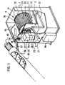
- Such a system for the removal of fats and oils consists, as here, as an example in Figure 1 shown from a square container 1.
- This can be made of chrome steel or be made of plastic, whereby polypropylene is particularly suitable because it is resistant is against fatty acids and even low pH values cannot harm it. So is also no corrosion problems to be expected in the long run.
- the container 1 has in his Inside a container space 9 separated from the partition 3, which contains the microbiological Contains module in the form of a drum 20, and in operation up to the drum axis is filled with a liquid medium.
- the bottom of this container space 9 forms one towards the bottom of the can 11.
- the container 9 in the back of the can 11 has one Drain 12.
- This lattice drum can be inside by additional plastic rods Compartments. It is used to operate the system with carrier materials for grease and oil-degrading microorganisms.
- the carrier materials with the populated on them Microorganisms are alternately contaminated with the drum 20 by the fat Water and medium, the level of which is up to about the middle of the drum shaft 29 enough, and then rotated again through the air above the level. They take oil and fat that is degraded by the microorganisms, as described below becomes.
- a fan 36 with check valve is installed, which Air can be blown into the interior of the container because of the microorganisms used are aerobic and require an air supply.
- the exhaust air is inside the container 1 through a hole present on the top of the overflow pipe 55 at its uppermost position blown, or through a special odor filter, not shown here, to the outside blown.
- the metering device for the fat and oil is as follows in the example shown realized: on the container 1 is an inlet pipe 56 made of acid-resistant plastic for the supplied and degradable oil and fat present, which is inclined into the interior of the container leads and opens there over the container space 9. From the container wall 6 that is Plastic tube 57 is flexible and is on the underside of a plastic tube 58 connected with a larger diameter, inside an Archimedes screw 59 is arranged, which has a shaft made of chrome steel and otherwise also made of acid-resistant Plastic is executed.
- This shaft is driven by a separate motor 60 driven, which is arranged for example at the upper end of the tube 58 as shown here can be.
- the lower end of the tube 58 can now be smell-tight into an existing one Grease separator system are guided, with its lower rim just a little there should be below the level in the grease separator system.
- the pipe 58 is attached depending on the situation by means of a bracket, not shown here. If necessary, the motor 60 can now be switched on, using the Archimedes screw 59 Oil and fat in the pipe 58 upwards, which then via the pipe 57.56 in reaches the container space 9 and is removed there by the microbiological module. The The resulting metabolic products are removed from the container 1 via the line 55 passed out and back into the grease trap.
- a heater in the container space can ensure the activity of the microorganisms 9 can be provided, for example in the form of a heating coil.
- a box 34 with a door attached in which a metering pump is housed. Further In this box there is a container for a nutrient that the microorganisms dosed is supplied.
- a hose or a pipeline 35 leads from this Box 34 from inside the container and there to the drum container 9, where the pipeline opens over the drum 20.
- a Control box attached, in which a programmable electrical control for the Motors 22,60, the fan 36 and the metering pump is housed.
- the facility will above through a cover, not shown here, which is supported on a rubber seal, tightly closed. Nowhere can bad smells come out, because if the Fan 36 is not running, the non-return valve closes the container 1, and if it runs, against the fan air there is no air with odor carriers from the inside out to pour.
- the cover of the system can be hinged, and then it is advantageously supported with gas springs and fixed at the free end by means of buckles can be locked. With such a design, the system can Maintenance purposes easily opened and closed again odor-tight.
- the metering device can Example can be realized by means of a pump and the air supply can be an alternative by using small air bubbles from below into the Container space 9 are blown in by the carrier material for the microorganisms swims. In this case, a rotating drum can be omitted. If necessary, can several plant units can be used in parallel to provide the necessary capacity for to achieve fat and oil degradation.
- the plant for the separation and subsequent removal of fats and oils in waste water additionally works as a grease separator by adding the one with the wastewater separable fats and oils float in the wastewater due to gravity and thus form a layer of fat and odor on the water surface.
- the separated fat and oil is metered into a microbiological module, and the fats and oils are degraded there microbiologically.
- the system still have facilities to accumulate difficult-to-separate particles to make it float, and further the wastewater treated so far can forced to flow through special material, to which the fat and oil particles have a special affinity and soak it up.
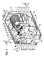
- the plant for separating and subsequent removal of the separated Bold as shown in Figure 2, are described. It consists of one square container 1. This can be made of chrome steel or plastic, whereby polypropylene is particularly suitable because it is resistant to fatty acids and to it even low pH values cannot harm it. This means that there are no corrosion problems in the long term to count.
- the system shown in the picture is one that is dimensioned for a kitchen with a capacity of about 400 meals a day. she is 1.30m long, 0.70m wide and 1.50m high and holds about 900 liters of wastewater.
- the whole Container space 7 of the container 1 between the side wall 6 and the partition 3 is in Operation filled with wastewater.
- the separable fatty substances float in this container part 7 and oil components and form a layer on the water surface.
- This oil and fat layer flows over the edge 4 through the comb 5 during operation, so that primarily the Grease and oil get into the room beyond partition 3.
- the comb 5 stops any floating solids back.
- the fats and oils also flow Waste water via the partition 3.
- the volume flowing over corresponds to that volume flowing through the inlet pipe 2.
- Container space 8 again separates those still floating in the waste water separable fats and oils.
- this container space 8 is installed from above a sealed from the container space 8, separate container space 9 with a Partition 10, which contains a microbiological module in the form of a drum 20.
- the underside of this container space 9 forms a can 11 falling towards the rear.
- the container 9 has a drain 12 in the back of this can 11, which leads into an overflow pipe 13 and via this back into the container 8, the mouth 14 of the overflow pipe 13 a few centimeters above the level of the lower edge of the drain pipe 15 of the Container 1 is arranged.
- the container space 8 has one rear inclined floor 16, which has recesses at the rear corners or is spaced over its entire width from the side wall 17 of the container 1.
- the space 18 below the inclined floor 16 is free here and the drain pipe 15 leads from it through the partition 3 into the container space 7, in this upwards and from there on one Level that is slightly below the level of the inlet pipe 2 to the outside.
- the Container space 7 acts as a sludge trap and sink space for any solids that with the Waste water get into the plant. This accumulated sludge and solids can are drained from time to time via the drain lines 19. If none to drain If there is a further gradient, a pump is connected to the drain line 19. Longitudinally through the container spaces 7 and 8 to the partition 10 of the container 9 there is a drive shaft 21 which is made of stainless steel. It is driven by one Electric motor 22 with angular gear 23.
- a stirring arm 24 is attached in the area of the container space 3 .
- One or more such agitator arms which are aligned with the axis 21 turn, thereby keeping the upper layer of fat, oil and water in the container space 7 constantly on the move. It has been shown that this measure prevents the floating of the Fats and oils on the one hand, and the decrease in solids and sludges on the other hand, is very beneficial.
- a plastic gear 27 is on a reinforcing plate 40 mounted on the partition 10. This engages in an equal size, gear 28 arranged below it.
- This gear wheel 28 has a shaft 29 connected from plastic, which forms the drum axis of a drum 20, which is in Container room 9 is located.
- This drum 20 has a drum disc on both sides 30.31, and these drum disks are along the circumference of the disks with plastic tubes 32 or plastic round rods connected so that a lattice drum 20 is formed is.
- This grid drum can be divided into compartments on the inside by further plastic rods.
- the drum 20 For the operation of the plant, it is filled with carrier materials for microorganisms, such as which will be described later, and the drum 20 then rotates these substrates with the microorganisms then populate alternately with the water contaminated with fat, whose level reaches about the middle of the drum shaft 29, and then through again the air above the level.
- the motor for rotating the drum points for this dimension a grease trap for a kitchen with a capacity of 400 meals a day Power of 370 watts.
- a fan 36 In the side wall 6 is a fan 36 with a check valve built-in, which allows air to be blown into the interior of the container because the microorganisms used are aerobic and require an air supply.
- the exhaust air is by an existing on the top of the drain pipe 15 at its highest point Hole 33 blown into the sewage system, or through a special one, not shown here Blown out odor filter. If the heat supplied with the fat and oil as well the ambient heat is insufficient to maintain a sufficient temperature for the activity of the Ensuring microorganisms can be a heating device for the container rooms 7, 8 and in particular 9 are provided, for example in the form of a heating coil. Below the Motors 22 is a box 34 with door attached, in which a metering pump is housed. This box also contains a container for a nutrient that Microorganisms are fed in doses.
- a hose or a pipeline leads to this 35 from this box into the interior of the container and there to the drum container 9, where the Pipeline 35 opens over the drum 20.
- a control box in which a programmable electrical Control for the motor 22, the fan 36 and the metering pump is housed.
- the facility is up here by one Lid not shown, which rests on a rubber seal, tightly closed. Nowhere can bad smells come out, because when the fan 36 is not running, the non-return flap closes the container, and when it is running it can hold the container Fan air no air to flow with odorants from the inside out.
- the lid the system can be designed to be hinged, it then advantageously using gas springs is supported and can be securely closed at the free end by means of buckles. With a Such execution, the system can easily be opened for maintenance purposes and again be sealed odor-tight.
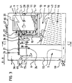
- FIG. 3 shows the system according to FIG. 2 in a sectional view from the long side seen.
- the individual parts are shown here schematically and the figure shows one Section through the system along the plane A-A in Figure 2.
- the system has a cover 46 on which rests on a rubber seal.
- An odor filter 47 is installed in this cover.
- the fan 36 which is built into the container wall 6, is indicated in the top left of the figure is. This blows the air through, for example, a pipe (not shown here) below in a lattice in which a piece of styrofoam fits into this lattice. Blows the Fan, the styrofoam piece is raised and the air can pass through the grille into the Get inside the container.
- the styrofoam piece is on the Vent pipe mouth and closes it.
- the inlet pipe 2 Under the fan 36 is the inlet pipe 2 shown.
- the grease and oil contaminated waste water runs through the inlet pipe 2 into the first one Container space 7, a baffle 61 being arranged in front of the mouth of the inlet pipe is. This prevents a surge of incoming sewage on the surface of the liquid forms a wave in the container space 7 with which excessive water is present the upper edge 4 of the partition 3 would run into the next container space 8.
- the baffle 61 should ensure that the freshly incoming waste water in the container space 7 first the solids and sludge sink and only the previously floated top layer, which in addition to water consists primarily of fat and oil, over the top edge 4 flows into the next container space 8.
- the drive shaft 21 carries in the area of Container space 7 two stirrer arms 24, which constantly in the upper layer of the liquid Keep moving. The level in this container space 7 is shown with a triangle 38 and is defined by the upper edge 4 of the partition 3. Over this edge 4 the floating fat and oil runs together with water into the next container room 8. The triangle 39 is the somewhat lower level in this container space 8 shown.
- the drive shaft 21 carries the scoop tube 26, which is attached eccentrically to the drive shaft 21.
- the drum shaft is on both sides 29 stored on a plastic bearing 53.54.
- the gear 27 can on the drive shaft 21st be shifted slightly against this, so that the drum 20 is easily removed from the Bearings 53,54 lifted out and can thus be removed from the drum container 9.
- the level in the drum container 9 is indicated by the triangle 41. As you can see, the level reaches approximately to the middle of the shaft 29 which carries the drum 20. This ensures that the bearings 53, 54 of the drum shaft 29 are exposed to the liquid be lubricated.
- the drum container 9 has a bottom at the bottom which is inclined Kännel 11 forms. From the outlet 12 in the can 11, an overflow pipe 13 leads under the Drum container 9 back and then up to the axis height of the drum shaft 29.
- This mouth 14 of the overflow pipe 13 defines the level 41 in the drum container 9.
- an inclined base 16 is installed in the container 1, which has recesses 43 in the form of holes or slots.
- Image are installed below the floor 16 slats 44 which run obliquely upwards, which have a surface affinity for fat and oil. They are close to each other in a multitude arranged and extend over the entire inner width of the container 1. From A drain pipe 15 passes through the area of these fins 44, which forms the container space 18 the partition 3 through and then up, where it goes through the container wall 6 leads outside. The bottom edge of the drain pipe 15 at the point where it passes through the container wall 6 is guided, defines the level 39 in the container space 8. At the bottom left of the container 1 you can still see a drain line 19 with a tap for the sludge and solids accumulate in container space 7.
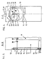
- the system is a schematic representation in a section along the plane C-C shown in Figure 2.
- This illustration helps to understand how the scoop tube 26 works.
- the scoop tube 26 sits eccentrically on the drive shaft 21.
- the inlet mouth 45 of the Scoop tube 26 describes the circle drawn.
- the one shown below Circle indicates the circumference of the drum 20.
- the pouring mouth 48 of the Scoop tube 26 is directed towards the rear in the direction of the drive axis 21. Below this Spout 48 of the scoop tube 26, the inlet channel 37 can be seen through the Opening 49 leads into the drum container 9.
- the drive shaft 21 can now turn on both sides.
- the scoop tube 26 dips with it Inlet mouth 45 into the oil separated and floated in the container space 8 and fat and skim a portion of it, this portion also containing water like.
- the level 39 in the container space 8 is indicated by the triangle 39.
- the scooped portion flows in the scoop tube 26 to its pouring mouth 48 and is finally poured onto the inlet channel 37, through which the fat, oil and water flows through the opening 49 into the drum container 9.
- the drive shaft 21 simultaneously drives the drum 20 and keeps it rotating. Because they driven by the two gears not shown here, it rotates in reverse Direction of rotation to the drive shaft 21.
- FIG. 5 shows a partial section along the plane B-B of FIG. 2. Is shown here the level 38 in the container space 7, which is slightly higher than the level 39 in adjoining container space 8, from which the fat and oil is skimmed off.
- the vertical Part of the drain pipe 15 is a precisely fitting pipe 50 with a bottom 51, that is permeable at the top and bottom by being perforated there as shown, for example.
- the tube 50 is equipped with a handle 52 at the top. His inside is filled with one special material 42, which has the ability to accumulate or absorb fat.
- the product MELT-BLOWN a textile composite, is suitable as a filling material made of polypropylene in granular form or as a tape, manufactured by the company ECOTEXTIL, 277 11 Hor ⁇ átky un Neratovic, Czech Republic.
- One gram of this The substance can accumulate about 12 to 18 grams of fat.
- the Tube 50 When flowing through the Tube 50 are thus the not yet separated or not separable fat and oil particles largely captured and retained by this material. If the Capacity of the material is exhausted, the tube 50 can be pulled out on the handle 52. The material is then emptied and replaced with new one. The oil and fat material is recycled by squeezing or centrifuging.
- solvents be used to extract the fat and oil substances. That through recycling accumulating fat and oil can be added to the container space 8 of the system.
- Figure 6 shows the system seen from above. All parts marked with numerals have been already described for the other figures.
- the drain pipe 15 designed as a square drain channel.
- the module consists of the actual grease separator functionally separated drum container 9 and the drum rotating in this container 20.
- This drum 20 is with carrier material for special fat and oil degrading Microorganisms filled. These aerobic microorganisms colonize this carrier material and when the drum 20 rotates, they are repeatedly immersed in the liquid in which drum 20 rotates, takes up oil and fat there and emerges again from this liquid open, then move through the air and are supplied with oxygen by it. They degrade the fats and oils.
- the result of the degradation Water has a low pH and is through the overflow line 13 in the Container space 8 of the fat separator, where it is with the large one located there
- the amount of water mixed so that its low pH has practically no effect on the Has pH in the container space 8 after mixing.
- By separating the drum container 9 of the remaining part of the system also becomes a buffer for temperature fluctuations educated. When a surge of hot water comes in from the dishwasher the system flows in, this has practically no influence on the temperature in the drum container 9.
- the amount of fat and oil supplied is not affected.
- the electrical control set or programmed so that, for example, the engine stops every hour and then it turns a few times in reverse. This draws on Scoop tube 26 a few servings in the drum container 9. How often this reversal of the Direction of rotation takes place and how many times the scoop tube 26 is to scoop is determined by Adapted case by case to the operating conditions of the respective kitchen and with the electrical Control programmed. The same is the case for the fan 36. This does not need to run constantly, but can, depending on the required activity of the microorganisms be switched on programmatically from time to time for a while. Further this also applies to the dosing pump for supplying additional nutrient solution for the Microorganisms in the drum 20.
- the specific microbiological aspects of this fat and oil degradation are disclosed below:
- lipases triazylglycerol of azylhydrolase, EC 3.1.1.3
- lipases in pure form are usually used for the hydrolysis of the triazylglycerols.
- the microorganisms that represent the major lipase producers include lipolytic yeasts, which are very often used biotechnologically. Your lipolytic enzymes are species-specific.
- Lipase synthesis in lipolytic yeasts is often positively influenced by the selected nitrogen source and the presence of citrate.
- Citric acid and in some cases also isocitric acid are the main metabolic products in the use of hydrocarbons, oils and fats as food sources for these microorganisms. The accumulation of these metabolic products in the cultivation medium causes their rapid acidification.
- the lipolytic yeast Yarrowia lipolytica is a particularly suitable microorganism for this plant for removing organic oils and fats, the Yarrowia lipolytica WI strain proving particularly suitable. The morphological and physiological properties of this yeast strain Yarrowia lipolytica WI are described and explained below.
- the yarrow strain Yarrowia lipolytica WI does not ferment maltose, sucrose, lactose, glucose, galactose and raffinose. It does not assimilate nitrates, but it assimilates L-lysine and erythritol. It grows at a temperature between 5 ° C and 35 ° C. It forms elliptical to oval cells in the liquid nutrient medium with oleic acid as the only carbon source. After 120 to 142 hours of cultivation, it forms pseudomycelium and real mycelium. There is no pigmentation. For growth in the synthetic medium, it does not require the presence of vitamins or any growth stimulators. This strain is sensitive to nystatin.
- von Arx is the amorphous form of Candida lipolytica (Harrison), Diddens et. Lodder. This microorganism was isolated from a soil contaminated with petroleum near an oil well in Hodonin, Czech Republic and deposited on April 16, 1996 at the Czech Microorganism Collection under the number CCM 4510 and under the same number a certificate of viability was issued. The address of this internationally recognized depository under the Budapest Treaty is: CCM - Czech Collection of Microorganisms, Masaryk University, Tvrdého 14, CR-602 00 Brno. A copy of the Receipt in the case of an Original Deposit and a copy of the Viability Statement are attached as Appendix 1 and Appendix 2 to the description.
- the high resistance of Yarrowia lipolytica WI to the effects of external factors, the low demands on the nutrient content in the environment, the strong viability and the high lipolytic activity make it possible to use this microorganism for biodegradation of fats and oils in closed containers and for continuous biodegradation of oils, greases and oil emulsions in the cleaning process of waste water contaminated in this way.
- the yeast strain is propagated and induced in the synthetic or organic medium in the presence of fatty acids or oils.
- the yeast is then used to colonize synthetic carriers for the microorganisms or these are used directly in the contaminated wastewater.
- the degradation of the oils and fats proceeds with the addition of air and with a sufficient concentration of nitrogen, whereby the ratio between the carbon contained in the oil or fat in this medium and the nitrogen must be maintained within the limits of the mass ratios 60 to 100: 1 .
- the optimal conditions for carrying out the process for the biodegradation of oils and fats using this yeast are at a pH of the medium of between 2.0 to 5.0 and at a temperature of 20 ° C. to 35 ° C.
- the organic or synthetic nutrient medium which forms a nitrogen and phosphorus source, mixed with other inorganic salts and trace elements as well as oleic acid or vegetable oil in a soluble form.
- the initial pH value of the cultivation medium can advantageously be adjusted to a value between 3.5 and 4.5 with citric acid, with intensive aeration with 0.3 to 1.0 liters of air per 1 liter of medium per hour at a temperature of 25 ° C up to 30 ° C the cultivation time is 24 to 72 hours.
- the end products of the biodegradation of oils and fats are carbon dioxide (CO 2 ), biomass and citric acid as the predominant metabolite.
- CO 2 carbon dioxide
- Other organic acids such as vinegar, apple, fumaric and oxoglutaric acids can also arise.
- these metabolites can also be converted into citric acid in the course of continuous fat biodegradation by the cells or used for biomass formation.
- the main advantage of this process for the biodegradation of fats and oils is that the resulting metabolites are primarily non-toxic and can easily be broken down by the usual microflora of biological wastewater treatment plants.
- Ribbons or fluffy cords made of synthetic fibers, preferably polyester, are suitable as the carrier material and can be populated with the cells induced by Yarrowia lipolytica WI .
- These ribbons or cords are wound in sections of approximately 1.50 m on approximately 10 cm long plastic tubes made of synthetic polymers, which have a diameter of, for example, 3 cm to 4 cm.
- the tubes are made of, for example, polyvinyl chloride, polyethylene or polypropylene.
- the drum 20 of the system which can be divided into several rooms, is filled with such wrapped pipe sections. Then this carrier material is populated with the cells induced by Yarrowia lipolytica WI , after which the system is ready for operation and the fat and oil can be added continuously or at intervals.
- the medium in the drum container 9 contained NH 4 + as a nitrogen source in a concentration of 100 mg / l to 400 mg / l.
- the pH in the medium was between 1.02 and 3.0 within 35 weeks.
- the temperature of the medium ranged between 25 ° C and 28 ° C.
- the water on leaving the system contained oil in a concentration of 38.25 mg / l to 48.12 mg / l (gravimetric determination after extraction into the organic solvent).
- Representatives of the species Yarrowia lipolytica in particular the strain Yarrowia lipolytica WI, have good lipolytic activity in the presence of oils and fats, similar to the presence of the emulsions of these substances in the water medium.
- the biodegradation rate of these contaminants of the water medium by the cells of the Yarrowia lipolytica Wl strain is within wide limits of the pH value between 0.8 and 7.0 and relatively high at temperatures of 5 ° C to 35 ° C.
- Conditions for achieving the optimal physiological activity of Yarrowia lipolytica WI are: Firstly, an adequate oxygen supply in limits between 0.3 and 1.0 liters of air per 1 liter of waste water and hour, secondly, a sufficient NH 4 + concentration of at least 60mg / l and third, a concentration of 0.1% to 3% (w / v) fat or oil in the medium.
- the wastewater discharged from the plant is only weakly acidified by the citric acid. It can be easily cleaned in the municipal sewage treatment plants.
Landscapes
- Chemical & Material Sciences (AREA)
- Chemical Kinetics & Catalysis (AREA)
- Thermal Sciences (AREA)
- Physics & Mathematics (AREA)
- Life Sciences & Earth Sciences (AREA)
- Microbiology (AREA)
- Hydrology & Water Resources (AREA)
- Biodiversity & Conservation Biology (AREA)
- Oil, Petroleum & Natural Gas (AREA)
- Engineering & Computer Science (AREA)
- Environmental & Geological Engineering (AREA)
- Water Supply & Treatment (AREA)
- Organic Chemistry (AREA)
- Removal Of Floating Material (AREA)
- Fats And Perfumes (AREA)
- Physical Water Treatments (AREA)
- Processing Of Solid Wastes (AREA)
Abstract
Description
Die vorliegende Erfindung betrifft im allgemeinen eine Anlage zum Beseitigen von Fetten und Oelen, wobei hierzu besondere fett- und öldegradierende Mikroorganismen zum Einsatz kommen. Im besonderen kann die Anlage zum gleichzeitigen Abscheiden und Beseitigen von Fetten und Oelen in Abwässern ausgelegt sein. Bei den in Betracht kommenden Fetten und Oelen kann es sich um verschiedene Arten handeln, zum Beispiel um mineralische, synthetische oder organische. Von besonderem Interesse sind hier die organischen Fette und Oele, wie sie vorallem in Hotels, Gaststätten und anderen Grossküchenbetrieben im Abwasser anfallen. Die Anlage kann jedoch auch für die Abwässer von Lebensmittelverarbeitenden Betrieben aller Art wie zum Beispiel für Schlachthäuser und Metzgereien konzipiert werden.The present invention relates generally to a plant for the removal of fats and oils, using special fat and oil degrading microorganisms come. In particular, the system can be used for simultaneous separation and removal of fats and oils in waste water. With those in question Fats and oils can be of different types, for example mineral, synthetic or organic. The organic ones are of particular interest here Fats and oils, such as those found in hotels, restaurants and other commercial kitchens accumulate in waste water. However, the plant can also be used for waste water from food processors Companies of all kinds, such as for slaughterhouses and butchers be conceived.
Viele Gemeinden haben zum Schutz ihrer Abwasser-Reinigungsanlagen, sowie um ein Zusetzen der Kanalisationsrohre zu verhindern, Einleitebedingungen für die gewerblichen Kanalanschlussnehmer festgelegt. Der zum Beispiel in Deutschland zulässige Gehalt an organischen Fetten und Oelen pro Liter Abwasser schwankt je nach Verwaltungsbezirk für solche gewerblichen Betriebe zwischen 50mg und 250mg, wobei zunehmend ein Grenzwert von 50mg vorgeschrieben wird. Deshalb werden von den betroffenen Betrieben Fettabscheide-Anlagen eingebaut. In Ballungszentren wird erfahrungsgemäss auf etwa 500 Einwohner eine solche Fettabscheide-Anlage betrieben. Many communities have to protect their wastewater treatment plants, as well as clogging of sewer pipes to prevent discharge conditions for commercial Channel connectee set. The allowable salary in Germany, for example organic fats and oils per liter of wastewater varies depending on the administrative district for such commercial establishments between 50mg and 250mg, with an increasing threshold of 50mg is prescribed. That is why the affected companies are removing grease traps built-in. Experience has shown that around 500 people live in metropolitan areas Residents operated such a grease trap system.
Im Zusammenhang mit dem Betrieb von konventionellen Fettabscheide-Anlagen, die aufgrund ihrer Funktion einzig aufgrund der Schwerkraft die Fette und Oele vom Wasser abscheiden, gibt es eine Reihe von Problemkreisen. Zunächst ist das tatsächliche Abscheidevermögen der Abscheideanlagen unter den in der Betriebspraxis stark schwankenden Bedingungen oftmals geringer als es zur Einhaltung der festgesetzten Grenzwerte nötig wäre. Bei der Bestimmung des Gesamtgehaltes an organischen Oelen und Fetten als polare lipophile Stoffe wird oft nicht beachtet, dass ein Fettabscheider wegen seiner Funktionsweise lediglich die abscheidbaren Anteile der lipophilen Leichtstoffe zurückhalten kann. Emulgierte, gelöste und dispergierte Fettanteile, wie sie infolge der eingesetzten Waschmittel und der hohen Temperaturen im Abwasser von Geschirrspülanlagen vorkommen, können damit nicht zurückgehalten werden. Das Fett befindet sich in einem ähnlichen Zustand wie jenes in der Milch, in welcher es Fettpartikel gibt, die bloss 0.1µm bis 10µm Durchmesser aufweisen und nicht aufschwimmen.In connection with the operation of conventional grease trap systems, due to their function solely due to gravity, the fats and oils from the water separate, there are a number of problem areas. First is the actual separability of the separating plants among those that fluctuate strongly in practice Conditions are often less than is necessary to comply with the specified limit values would. When determining the total content of organic oils and fats as polar Lipophilic substances are often neglected as a grease trap because of how it works can only retain the separable portions of the lipophilic light materials. Emulsified, dissolved and dispersed fat components as they result from the detergents used and the high temperatures in the wastewater from dishwashers so as not to be held back. The fat is in a similar condition as that in milk, in which there are fat particles that are only 0.1µm to 10µm in diameter exhibit and do not float.
Weiter sollte ein konventioneller Fettabscheider ca. alle zwei bis vier Wochen entleert und gereinigt werden, wofür der Betreiber der Anlage zuständig ist. Fettabscheider in Metzgereien sollten mindestens einmal wöchentlich oder aber spätestens bei Füllung des Fett-Speichervolumens gereinigt werden. Fettabscheider in Küchenbetrieben sollten in der Regel alle 14 Tage entleert werden. Der Abwasseranfall und die Abwasserbeschaffenheit schwankt jedoch selbst unter Küchenbetrieben mit anzahlmässig gleichgrossem Ausstoss von Essen. Untersuchungen haben gezeigt, dass wegen der Verschiedenartigkeit der Speisen und deren Zubereitung der Fettgehalt im Abwasser einer Spitalküche, die täglich 1'000 Essen produziert, im Durchschnitt zum Beispiel ca. 500 mg/l beträgt, während er bei einer Truppenküche bei ca. 1'500 mg/l liegt, also beim Dreifachen. Pro Essen rechnet man mit einem Fettanfall von 3 bis 30 Gramm. Je nach den Gegebenheiten des angeschlossenen Küchenbetriebes müssen die Fettabscheider mehr oder weniger oft entleert werden. Zum regelmässigen Entleeren des Fettabscheiders wird dieser geöffnet und danach wird die Saugleitung eines Entsorgungsfahrzeuges eingebracht. Der beim Absaugen des Fettabscheiderinhaltes auftretende ekelerregende Gestank führt dabei zu einer sehr unangenehmen Geruchsbelästigung in der unmittelbaren Umgebung der Anlage. Nach dem Entleeren der Fettabscheideranlage wird diese mit Heissdampf gereinigt. Diese unbedingt notigen Wartungsarbeiten sind mit Umtrieben und erheblichen und immer wieder anfallenden Kosten verbunden. Um die abzutransportierenden Volumina zu reduzieren, sind Fettabscheider-Systeme bekanntgeworden, bei denen das abgeschiedene Fett in gesonderte Behälter gepresst wird, sodass nur noch das eigentliche abgeschiedene Material abtransportiert und einer Entsorgung oder Wiederverwertung zugeführt werden muss. Trotzdem sind jedoch regelmässige teure Abtransporte nötig, welche zusätzlich die Umwelt belasten.Furthermore, a conventional grease separator should be emptied approximately every two to four weeks cleaned, for which the operator of the system is responsible. Fat separators in butchers should be at least once a week or at the latest when the fat storage volume is filled getting cleaned. Grease traps in kitchen businesses should usually all Be emptied for 14 days. The amount of waste water and the quality of the waste water fluctuate however, even among kitchen businesses with the same number of meals. Studies have shown that because of the diversity of the dishes and their Preparation of the fat content in the wastewater of a hospital kitchen that produces 1,000 meals a day, on average, for example, is about 500 mg / l while in a troop kitchen is around 1,500 mg / l, i.e. three times as much. One expects a fat attack per meal from 3 to 30 grams. Depending on the circumstances of the connected kitchen company the grease separators must be emptied more or less often. For regular emptying the grease trap is opened and then the suction line of a disposal vehicle brought in. The one that occurs when the grease separator contents are sucked off disgusting stench leads to a very unpleasant odor in the immediate vicinity of the facility. After emptying the grease separator system cleaned with hot steam. This maintenance work, which is absolutely necessary, is carried out with activities and considerable and recurring costs. To remove the To reduce volumes, grease trap systems have become known which the separated fat is pressed into separate containers so that only that actual deposited material is removed and disposed of or recycled must be fed. Nevertheless, they are regularly expensive to transport necessary, which also pollute the environment.
Es ist deshalb im allgemeinen die Aufgabe der vorliegenden Erfindung, eine Anlage zum Beseitigen von Fetten und Oelen egal welcher Herkunft zu schaffen, welche die sonst damit anfallenden Kosten einspart oder zumindest reduziert.It is therefore generally the object of the present invention to provide a plant for Removal of fats and oils no matter what origin to create, which otherwise costs incurred or at least reduced.
Im besonderen ist es eine Aufgabe der vorliegenden Erfindung, eine Anlage zum Abscheiden und nachfolgenden Beseitigen von Fetten und Oelen in Abwässern zu schaffen, welche einen regelmässigen Abtransport des Fettabscheiderinhaltes oder des abgeschiedenen Fettes erübrigt und somit die damit anfallenden Kosten einspart, und welche die Geruchsbelästigung, die von einem herkömmlichen Fettabscheider ausgeht, eliminiert.In particular, it is an object of the present invention to provide a separation system and subsequent removal of fats and oils in waste water, which regular removal of the fat separator contents or the separated fat superfluous and thus saves the costs incurred, and which the unpleasant smell, that starts with a conventional grease separator.
In einer besonderen Ausführung ist es eine zusätzliche Aufgabe der Anlage zum Abscheiden und nachfolgenden Beseitigen von Fetten und Oelen in Abwässern, eine verbesserte Zurückhaltung der Fette und Oele im Abwasser zu erzielen und damit tiefere Grenzwerte an lipophilen Stoffen im ausfliessenden Abwasser zu erreichen.In a special version, it is an additional task of the separation plant and subsequent removal of fats and oils in waste water, an improved reluctance the fats and oils in the wastewater and thus lower limit values to achieve lipophilic substances in the effluent.
Die allgemeine Aufgabe wird gelöst von einer Anlage zum Beseitigen von Fetten und Oelen,
die sich durch die Merkmale des Patentanspruches 1 auszeichnet.The general task is solved by a plant for the removal of fats and oils,
which is characterized by the features of
Die besondere Aufgabe zur Schaffung einer Anlage zum Abscheiden und nachfolgenden
Beseitigen von Fetten und Oelen in Abwässern wird gelöst von einer Anlage gemäss den
Merkmalen des abhängigen Patentanspruches 2.The special task of creating a facility for separation and subsequent
Removal of fats and oils in waste water is solved by a system according to the
Features of
Die zusätzliche Aufgabe zur verbesserten Zurückhaltung der Fette und Oele im Abwasser
wird gelöst von einer Anlage mit den kennzeichnenden Merkmalen des abhängigen Patentanspruches
7. The additional task of improving the retention of fats and oils in waste water
is solved by a system with the characterizing features of the
In den Zeichnungen wird sowohl eine Anlage zum blossen Beseitigen von Fetten und Oelen wie auch eine spezifische Anlage zum Abscheiden und nachfolgenden Beseitigen von Fetten und Oelen in Abwässern gezeigt. Anhand dieser beispielsweisen Ausführungen werden diese Anlagen nachfolgend im einzelnen beschrieben und ihre Funktion wird erläutert.In the drawings there is a system for the mere removal of fats and oils as well as a specific system for separating and subsequently removing greases and oils shown in waste water. On the basis of these exemplary statements, these are Plants are described in detail below and their function is explained.
Es zeigt:
- Figur 1:
- Eine Anlage zum Beseitigen von Fetten und Oelen in einer perspektivischen Ansicht, teilweise aufgeschnitten;
Figur 2- Eine Anlage zum Abscheiden und nachfolgenden Beseitigen von Fetten und Oelen in Abwässern in einer perspektivischen Ansicht, teilweise aufgeschnitten;
- Figur 3:
- Die Anlage gemäss
Figur 2 von der Seite her gesehen schematisch, in einem Schnitt längs der Ebene A-A inFigur 2; - Figur 4:
- Die Anlage gemäss
Figur 2 von links her gesehen schematisch, in einem Schnitt längs der Ebene C-C inFigur 2; - Figur 5:
- Die Anlage gemäss
Figur 2 von der Seite her gesehen schematisch, in einem Schnitt längs der Ebene B-B inFigur 2.
- Figure 1:
- A plant for the removal of fats and oils in a perspective view, partially cut away;
- Figure 2
- A plant for the separation and subsequent removal of fats and oils in waste water in a perspective view, partially cut away;
- Figure 3:
- The system according to Figure 2 seen from the side schematically, in a section along the plane AA in Figure 2;
- Figure 4:
- The system according to Figure 2 seen from the left schematically, in a section along the plane CC in Figure 2;
- Figure 5:
- The system according to FIG. 2 seen schematically from the side, in a section along the plane BB in FIG. 2.
Die Anlage zum Beseitigen von Fetten und Oelen ist wahlweise als Zusatzanlage zu einer bestehenden Fettabscheideanlage gedacht, um das darin abgeschiedene Fett fortlaufend zu beseitigen, oder aber als gesonderte Anlage zum Betrieb einer zentralen Entsorgestation für Abfallfette und -Oele, in denen grosse Mengen von Fettabscheiderinhalten aus regelmässig ausgepumpten Fettabscheidern behandelt werden können. Kernstück der Anlage ist ein Behälterraum mit einem flüssigen Medium darin, in dem ein mikrobiologisches Modul vorhanden ist, das ein Trägermaterial einschliesst, welches mit fett- und öldegradierenden Mikroorganismen besiedelt ist, wobei eine Zudosiereinrichtung es ermöglicht, diesem Behälterraum und somit den darin befindlichen Mikroorganismen Fett und Oel dosiert zuzuführen. The system for the removal of fats and oils is optionally available as an additional system existing fat separator system is thought to continuously increase the fat separated in it eliminate, or as a separate system for the operation of a central disposal station for Waste fats and oils in which large amounts of fat separator contents are made regularly pumped out fat separators can be treated. The heart of the system is a container room with a liquid medium in it, in which a microbiological module is present is that includes a carrier material that contains fat and oil degrading microorganisms is populated, a metering device allowing this container space and thus supply the microorganisms in it with fat and oil.
Die Mikroorganismen degradieren sodann das Fett und Oel, wodurch sich der pH-Wert im flüssigen Medium des Behälterraumes absenkt. Wichtig ist dabei, dass die Randbedingungen für eine hohe Aktivität der eingesetzten Mikroorganismen eingehalten werden können. Nebst der dosierten Zufuhr von Fett und Oel wird den Mikroorganismen bedarfsweise auch Luft und Nährlösung zugeführt.The microorganisms then degrade the fat and oil, which causes the pH in the liquid medium of the container space is lowered. It is important that the boundary conditions can be observed for a high activity of the microorganisms used. In addition to the metered supply of fat and oil, the microorganisms also need if necessary Air and nutrient solution supplied.
Eine solche Anlage zum Beseitigen von Fetten und Oelen besteht wie hier als Beispiel in
Figur 1 gezeigt aus einem viereckigen Behälter 1. Dieser kann aus einem Chromstahl oder
aus Kunststoff gebaut sein, wobei sich Polypropylen besonders gut eignet, da es resistent
gegen Fettsäuren ist und ihm auch tiefe pH-Werte nichts anhaben können. Somit ist auch
auf Dauer mit keinen Korrosionsproblemen zu rechnen. Der Behälter 1 weist in seinem
Inneren einen von der Trennwand 3 abgetrennten Behälterraum 9 auf, der das mikrobiologische
Modul in Form einer Trommel 20 enthält, und der im Betrieb bis zur Trommelachse
von einem flüssigen Medium gefüllt ist. Die Unterseite dieses Behälterraumes 9 bildet einen
gegen hinten abfallenden Kännel 11. Hinten hat der Behälter 9 in diesem Kännel 11 einen
Ablauf 12. Dieser führt in ein Ueberlaufrohr 55, welches aus dem Behälter 1 herausführt,
wobei seine innere Unterkante beim Auslauf das Niveau des Mediums im Behälterraum 9
definiert. Auf der Seite 6 des Behälters 1 ist ein Elektromotor 22 mit Winkelgetriebe 23
angeordnet, dessen Antriebswelle 21 über zwei übereinanderliegende Zahnräder 27,28 die
Trommel 20 dreht. Das Flüssigkeitsniveau im Behälterraum 9 reicht dabei bis zur Achse des
unteren Zahnrades 28. Damit ist sichergestellt, dass die Trommellager geschmiert sind und
der Behälter 1 stets dicht bleibt, denn die Antriebswelle 21 durchsetzt die Behälterwand 6
oberhalb des Pegelstandes der Flüssigkeit. Die Trommel 20 weist auf beiden Seiten eine
Trommelscheibe 30,31 auf, und diese Trommelscheiben sind längs des Umfangs der Scheiben
mit Kunststoffrohren 32 oder Kunststoff-Rundstäben verbunden, sodass eine Gittertrommel
20 gebildet ist. Diese Gittertrommel kann innen durch weitere Kunststoffstäbe in
Abteile unterteilt sein. Sie wird für den Betrieb der Anlage mit Trägermaterialien für fett-
und öldegradierende Mikroorganismen befüllt. Die Trägermaterialien mit den darauf besiedelten
Mikroorganismen werden mit der Trommel 20 abwechslungsweise durch das fettbelastete
Wasser und Medium, dessen Pegelstand ja bis etwa zur Mitte der Trommelwelle 29
reicht, und dann wieder durch die Luft oberhalb des Pegels gedreht. Dabei nehmen sie Oel
und Fett auf, das von den Mikroorganismen degradiert wird, wie das noch beschrieben
wird. In der Seitenwand 6 ist ein Ventilator 36 mit Rückschlagklappe eingebaut, der das
Einblasen von Luft in das Behälterinnere erlaubt, weil die eingesetzten Mikroorganismen
aerob sind und einer Luftzufuhr bedürfen. Die Abluft wird im Innern des Behälters 1 durch
ein auf der Oberseite des Ueberlaufrohres 55 an dessen oberster Stelle vorhandenes Loch
geblasen, oder durch einen speziellen, hier nicht eingezeichneten Geruchfilter nach aussen
geblasen. Die Zudosiereinrichtung für das Fett und Oel ist im gezeigten Beispiel wie folgt
realisiert: Am Behälter 1 ist ein Einlaufrohr 56 aus säurebeständigem Kunststoff für das
zugeführte und zu degradierende Oel und Fett vorhanden, das geneigt in das Behälterinnere
führt und dort über dem Behälterraum 9 mündet. Von der Behälterwand 6 aus ist das
Kunststoff-Rohr 57 flexibel ausgeführt und ist an der Unterseite eines Kunststoff-Rohres 58
mit grösserem Durchmesser angeschlossen, in dessen Innerem eine Archimedes-Schraube
59 angeordnet ist, die eine Welle aus Chromstahl aufweist und sonst ebenfalls aus säurebeständigem
Kunststoff ausgeführt ist. Diese Welle wird von einem gesonderten Motor 60
angetrieben, der zum Beispiel wie hier gezeigt am oberen Ende des Rohres 58 angeordnet
sein kann. Das Rohr 58 kann nun mit seinem unteren Ende geruchsdicht in eine bestehende
Fettabscheideranlage geführt werden, wobei sein unterer Mündungsrand dort gerade etwas
unterhalb des Pegelstandes in der Fettabscheideanlage zu liegen kommen soll. Das Rohr 58
wird dabei je nach Situation mittels einer hier nicht dargestellten Halterung befestigt.
Bedarfsweise kann nun der Motor 60 eingeschaltet werden, wobei die Archimedes-Schraube
59 Oel und Fett im Rohr 58 aufwärts fördert, das dann über das Rohr 57,56 in
den Behälterraum 9 gelangt und dort vom mikrobiologischen Modul beseitigt wird. Die
dabei entstehenden Stoffwechselprodukte werden über die Leitung 55 aus dem Behälter 1
hinaus und zurück in den Fettabscheider geleitet. Falls die mit dem Fett und Oel zugeführte
Wärme sowie die Umgebungswärme nicht ausreicht, um eine genügende Temperatur für die
Aktivität der Mikroorganismen sicherzustellen, kann eine Heizeinrichtung im Behälterraum
9 vorgesehen werden, zum Beispiel in Form einer Heizschlange. Unterhalb des Motors 22
ist ein Kasten 34 mit Türe angebaut, in dem eine Dosierpumpe untergebracht ist. Weiter
befindet sich in diesem Kasten ein Behälter für ein Nährmittel, das den Mikroorganismen
dosiert zugeführt wird. Hierzu führt ein Schlauch oder eine Rohrleitung 35 von diesem
Kasten 34 aus in das Behälterinnere und dort zum Trommelbehälter 9, wo die Rohrleitung
über der Trommel 20 mündet. Auf der hier nicht einsehbaren Rückseite der Anlage ist ein
Schaltkasten angebaut, in dem eine speicherprogrammierbare elektrische Steuerung für die
Motoren 22,60, den Ventilator 36 und die Dosierpumpe untergebracht ist. Die Anlage wird
oben durch einen hier nicht eingezeichneten Deckel, der auf einer Gummidichtung lagert,
dicht verschlossen. Nirgends können somit üble Gerüche nach aussen treten, denn wenn der
Ventilator 36 nicht läuft, verschliesst die Rückschlagklappe den Behälter 1, und wenn er
läuft, vermag gegen die Ventilatorluft keine Luft mit Geruchsträgern von innen nach aussen
zu strömen. Der Deckel der Anlage kann scharnierend ausgeführt sein, wobei er dann
vorteilhaft mit Gasfedern abgestützt ist und am freien Ende mittels Schnallen fest
verschlossen werden kann. Mit einer solchen Ausführung kann die Anlage zu
Wartungszwecken leicht geöffnet und wieder geruchsdicht verschlossen werden. Eine
derartige Anlage kann dem Prinzip nach in verschiedensten Dimensionen und auch mit
anderen technischen Lösungen ausgeführt werden. Die Zusdosiereinrichtung kann zum
Beispiel mittels einer Pumpe realisiert werden und die Luftzufuhr kann als Alternative
dadurch erfolgen, dass mit Hilfe von Luftsieben kleine Mikrobläschen von unten in den
Behälterraum 9 eingeblasen werden, indem das Trägermaterial für die Mikroorganismen
schwimmt. In diesem Fall kann eine drehende Trommel entfallen. Im Bedarfsfall können
mehrere Anlage-Einheiten parallel geschaltet eingesetzt werden, um die nötige Kapazität für
die Fett- und Oeldegradation zu erreichen.Such a system for the removal of fats and oils consists, as here, as an example in
Figure 1 shown from a
Die Anlage zum Abscheiden und nachfolgenden Beseitigen von Fetten und Oelen in Abwässern arbeitet zusätzlich selbst als Fettabscheider, indem die mit dem Abwasser eingetragenen abscheidbaren Fette und Oele aufgrund der Schwerkraft im Abwasser aufschwimmen und somit an der Wasseroberfläche eine Fett- und Odschicht bilden. In gleicher Weise wird dann das abgeschiedene Fett- und Oel einem mikrobiologischen Modul dosiert zugeführt, und die Fette und Oele werden dort mikrobiologisch degradiert. Zusätzlich kann die Anlage noch über Einrichtungen verfügen, um schwer abscheidbare Partikel durch deren Akkumulation zum Aufschimmen zu bringen, und weiter kann das soweit behandelte Abwasser zwangsweise durch spezielles Material durchströmen, zu welchem die Fett- und Oelpartikel eine besondere Affinität aufweisen und sie aufsaugen.The plant for the separation and subsequent removal of fats and oils in waste water additionally works as a grease separator by adding the one with the wastewater separable fats and oils float in the wastewater due to gravity and thus form a layer of fat and odor on the water surface. In the same way then the separated fat and oil is metered into a microbiological module, and the fats and oils are degraded there microbiologically. In addition, the system still have facilities to accumulate difficult-to-separate particles to make it float, and further the wastewater treated so far can forced to flow through special material, to which the fat and oil particles have a special affinity and soak it up.
Im folgenden soll die Anlage zum Abscheiden und nachfolgenden Beseitigen des abgeschiedenen
Fettes, wie sie in Figur 2 dargestellt ist, beschrieben werden. Sie besteht aus einem
viereckigen Behälter 1. Dieser kann aus einem Chromstahl oder aus Kunststoff gebaut sein,
wobei sich Polypropylen besonders gut eignet, da es resistent gegen Fettsäuren ist und ihm
auch tiefe pH-Werte nichts anhaben können. Somit ist auch auf Dauer mit keinen Korrosionsproblemen
zu rechnen. Bei der im Bild gezeigten Anlage handelt es sich um eine, die
für eine Küche mit einer Kapazität von etwa 400 Essen pro Tag dimensioniert ist. Sie ist
1.30m lang, 0.70m breit und 1.50m hoch und fasst etwa 900 Liter Abwasser. Diese Anlagen-Dimension
ist die weitaus am meisten benötigte und für eine solche Küchenkapazität ist
die Anlage so kompakt, dass sie zum nachträglichen Einbau in einem Kellergeschoss auch
durch einen relativ engen Treppenabgang, wie er in alten Gebäuden oft anzutreffen ist, problemlos
transportiert werden kann. Es versteht sich, dass die Anlage für andere Küchenkapazitäten
entsprechend grösser dimensioniert werden kann. Das nötige Fassungsvermögen
der Anlage wird gemäss den Erfahrungswerten für konventionelle Fettabscheider
bestimmt und muss sicherstellen, dass auch bei grossem Schwallwasseranfall das Abwasser
in der Anlage eine genügende mittlere Verweilzeit aufweist, damit die abscheidbaren Fette
und Oele aufschwimmen können. In den Behälter 1 führt das Einlaufrohr 2, durch welches
das fettbelastete Abwasser in den Behälter 1 strömt. Im Behälterinnern ist eine erste Trennwand
3 angeordnet, deren Oberkante 4 mit einer Art Kamm 5 ausgerüstet ist. Der ganze
Behälterraum 7 des Behälters 1 zwischen der Seitenwand 6 und der Trennwand 3 ist im
Betrieb mit Abwasser gefüllt. In diesem Behälterteil 7 schwimmen die abscheidbaren Fett-
und Oelanteile auf und bilden an der Wasseroberfläche eine Schicht. Diese Oel- und Fettschicht
überströmt im Betrieb die Kante 4 durch den Kamm 5, sodass in erster Linie die
Fette und Oele in den Raum jenseits der Trennwand 3 gelangen. Der Kamm 5 hält dabei
allfällig aufschwimmende Feststoffe zurück. Mit den Fetten und Oelen strömt natürlich auch
Abwasser über die Trennwand 3. Das jeweils überströmende Volumen entspricht dem
gerade durch das Einlaufrohr 2 einströmenden Volumen. Im hinter der Trennwand 3 befindlichen
Behälterraum 8 erfolgt erneut eine Abscheidung der noch im Abwasser schwebenden
abscheidbaren Fette und Oele. In diesem Behälterraum 8 von oben eingebaut befindet sich
ein gegenüber dem Behälterraum 8 abgedichteter, gesonderter Behälterraum 9 mit einer
Trennwand 10, welcher ein mikrobiologisches Modul in Form einer Trommel 20 enthält.
Die Unterseite dieses Behälterraumes 9 bildet einen gegen hinten abfallenden Kännel 11.
Hinten hat der Behälter 9 in diesem Kännel 11 einen Ablauf 12. Dieser führt in ein Ueberlaufrohr
13 und über dieses zurück in den Behälter 8, wobei die Mündung 14 des Ueberlaufrohres
13 einige Zentimeter oberhalb des Niveaus der Unterkante des Abflussrohres 15 des
Behälters 1 angeordnet ist. Unterhalb des Kännels 11 weist der Behälterraum 8 einen nach
hinten geneigten Boden 16 auf, der an den hinteren Ecken Ausnehmungen aufweist oder
über seine ganze Breite von der Seitenwand 17 des Behälters 1 beabstandet ist. Der Raum
18 unterhalb des geneigten Bodens 16 ist hier frei und von ihm aus führt das Abflussrohr 15
durch die Trennwand 3 in den Behälterraum 7, in diesem nach oben und von dort auf einem
Niveau, das geringfügig unterhalb vom Niveau des Zulaufrohrs 2 liegt, nach aussen. Der
Behälterraum 7 wirkt als Schlammfang und Sinkraum für allfällige Feststoffe, die mit dem
Abwasser in die Anlage gelangen. Diese angesammelten Schlämme und Feststoffe können
über die Ablass-Leitungen 19 von Zeit zu Zeit abgelassen werden. Falls zum Ablassen kein
weiteres Gefälle vorhanden ist, wird an der Ablassleitung 19 eine Pumpe angeschlossen.
Längs durch die Behälterräume 7 und 8 bis hin zur Trennwand 10 des Behälters 9 erstreckt
sich eine Antriebswelle 21, die aus Edelstahl gefertigt ist. Sie wird angetrieben von einem
Elektromotor 22 mit Winkelgetriebe 23. Im Bereich des Behälterraumes 3 ist an diese Welle
21 ein Rührarm 24 angebaut. Einer oder mehrere solcher Rührarme, die sich mit der Achse
21 mitdrehen, halten dadurch die obere Schicht von Fett, Oel und Wasser im Behälterraum
7 ständig in Bewegung. Es hat sich gezeigt, dass diese Massnahme dem Aufschwimmen der
Fette und Oele einerseits, sowie dem Absinken der Feststoffe und Schlämme andrerseits,
sehr förderlich ist. In der Mitte ist auf der Trennwand 3 ein Zwischenlager 25 für die Welle
21 montiert. Im Bereich des Behälterraumes 8, das heisst zwischen der Trennwand 3 und
der Trennwand 10 des Behälters 9 ist an der Antriebswelle 21 ein Schöpfrohr 26 angebaut,
dessen Funktion noch erklärt wird. Am Ende der Welle 21 ist ein Kunststoff-Zahnrad 27 auf
einer Verstärkungsplatte 40 an der Trennwand 10 montiert. Dieses greift in ein gleichgrosses,
darunter angeordnetes Zahnrad 28 ein. Dieses Zahnrad 28 ist mit einer Welle 29
aus Kunststoff verbunden, welche die Trommelachse einer Trommel 20 bildet, die sich im
Behälterraum 9 befindet. Diese Trommel 20 weist auf beiden Seiten eine Trommelscheibe
30,31 auf, und diese Trommelscheiben sind längs des Umfangs der Scheiben mit Kunststoffrohren
32 oder Kunststoff-Rundstäben verbunden, sodass eine Gittertrommel 20 gebildet
ist. Diese Gittertrommel kann innen durch weitere Kunststoffstäbe in Abteile unterteilt sein.
Sie wird für den Betrieb der Anlage mit Trägermaterialien für Mikroorganismen befüllt, wie
das noch beschrieben wird, und die Trommel 20 dreht dann diese Trägermaterialien mit den
darauf besiedelten Mikroorganismen abwechslungsweise durch das fettbelastete Wasser,
dessen Pegelstand bis etwa zur Mitte der Trommelwelle 29 reicht, und dann wieder durch
die Luft oberhalb des Pegels. Der Motor zum Drehen der Trommel weist für diese Dimension
eines Fettabscheiders für eine Küche mit einer Kapazität von 400 Essen pro Tag eine
Leistung von 370 Watt auf. Entsprechend werden pro Tag (im 24 Stunden-Betrieb) ca.
9kWh elektrische Energie benötigt. In der Seitenwand 6 ist ein Ventilator 36 mit Rückschlagklappe
eingebaut, der das Einblasen von Luft in das Behälterinnere erlaubt, weil die
eingesetzten Mikroorganismen aerob sind und einer Luftzufuhr bedürfen. Die Abluft wird
durch ein auf der Oberseite des Abflussrohres 15 an dessen höchster Stelle vorhandenes
Loch 33 in die Kanalisation geblasen, oder durch einen speziellen, hier nicht eingezeichneten
Geruchfilter nach aussen geblasen. Falls die mit dem Fett und Oel zugeführte Wärme sowie
die Umgebungswärme nicht ausreicht, um eine genügende Temperatur für die Aktivität der
Mikroorganismen sicherzustellen, kann eine Heizeinrichtung für die Behälterräume 7,8 und
insbesondere 9 vorgesehen werden, zum Beispiel in Form einer Heizschlange. Unterhalb des
Motors 22 ist ein Kasten 34 mit Türe angebaut, in dem eine Dosierpumpe untergebracht ist.
Weiter befindet sich in diesem Kasten ein Behälter für ein Nährmittel, das den
Mikroorganismen dosiert zugeführt wird. Hierzu führt ein Schlauch oder eine Rohrleitung
35 von diesem Kasten aus in das Behälterinnere und dort zum Trommelbehälter 9, wo die
Rohrleitung 35 über der Trommel 20 mündet. Auf der hier nicht einsehbaren Rückseite der
Anlage ist ein Schaltkasten angebaut, in dem eine speicherprogrammierbare elektrische
Steuerung für den Motor 22, den Ventilator 36 und die Dosierpumpe untergebracht ist. Die
Funktion der Steuerung wird später noch erklärt. Die Anlage wird oben durch einen hier
nicht eingezeichneten Deckel, der auf einer Gummidichtung lagert, dicht verschlossen.
Nirgends können üble Gerüche nach aussen treten, denn wenn der Venitilator 36 nicht läuft,
verschliesst die Rückschlagklappe den Behälter, und wenn er läuft, vermag gegen die
Ventilatorluft keine Luft mit Geruchsträgern von innen nach aussen zu strömen. Der Deckel
der Anlage kann scharnierend ausgeführt sein, wobei er dann vorteilhaft mit Gasfedern
abgestützt ist und am freien Ende mittels Schnallen fest verschlossen werden kann. Mit einer
solchen Ausführung kann die Anlage zu Wartungszwecken leicht geöffnet und wieder
geruchsdicht verschlossen werden.In the following, the plant for separating and subsequent removal of the separated
Bold, as shown in Figure 2, are described. It consists of one
Die Figur 3 zeigt die Anlage gemäss Figur 2 in einer Schnittansicht von der Längsseite her
gesehen. Die einzelnen Teile sind hier schematisiert dargestellt und die Figur zeigt einen
Schnitt durch die Anlage längs der Ebene A-A in Figur 2. Die Anlage weist einen Deckel 46
auf, der auf einer Gummidichtung lagert. In diesem Deckel ist hier ein Geruchfilter 47 eingebaut.
Links oben im Bild ist der Ventilator 36 angedeutet, der in die Behälterwand 6 eingebaut
ist. Dieser bläst die Luft zum Beispiel über ein hier nicht dargestelltes Rohr von
unten in ein Gitter, in dem ein in dieses Gitter passendes Stück Styropor liegt. Bläst der
Ventilator, so wird das Styroporstück angehoben und die Luft kann durch das Gitter in das
Behälterinnere gelangen. Bläst der Ventilator nicht, so liegt das Styroporstück auf der
Ventilatorrohrmündung auf und verschliesst sie. Unter dem Ventilator 36 ist das Einlaufrohr
2 dargestellt. Durch das Einlaufrohr 2 läuft das fett- und ölbelastete Abwasser in den ersten
Behälterraum 7, wobei vor der Mündung des Einlaufrohres eine Prallwand 61 angeordnet
ist. Diese verhindert, dass sich bei einem Schwall von einlaufendem Abwasser an der Flüssigkeitsoberfläche
im Behälterraum 7 eine Welle bildet, mit der übermässig viel Wasser über
die Oberkante 4 der Trennwand 3 in den nächsten Behälterraum 8 laufen würde. Vielmehr
soll die Prallwand 61 sicherstellen, dass aus dem frisch einlaufenden Abwasser im Behälterraum
7 zunächst die Feststoffe und Schlämme absinken und nur die zuvor aufgeschwommene
oberste Schicht, die nebst Wasser vorallem aus Fett und Oel besteht, über die Oberkante
4 in den nächsten Behälterraum 8 fliesst. Die Antriebswelle 21 trägt im Bereich des
Behälterraumes 7 zwei Rührarme 24, welche die obere Schicht der Flüssigkeit ständig in
Bewegung halten. Der Pegelstand in diesem Behälterraum 7 ist mit einem Dreieck 38 eingezeichnet
und wird von der Oberkante 4 der Trennwand 3 definiert. Ueber diese Kante 4
läuft das aufgeschwommene Fett und Oel zusammen mit Wasser in den nächsten Behälterraum
8. Mit dem Dreieck 39 ist der etwas niedrigere Pegelstand in diesem Behälterraum 8
dargestellt. Im Bereich des Behälterraumes 8 trägt die Antriebswelle 21 das Schöpfrohr 26,
das exzentrisch an der Antriebswelle 21 befestigt ist. Durch die Trennwand 10 des Trommelbehälters
9 führt oben ein Einleitkanal 37. Wenn sich das Schöpfrohr 26 mit der Welle
21 dreht, schöpft es mit seiner im Bild gegen hinten gerichteten Einlaufmündung eine Portion
Fett, Oel und Wasser. Dreht das Schöpfrohr 26 aus der gezeigten Position weiter gegen
hinten und dann aufwärts, so fliesst die geschöpfte Flüssigkeitsmenge im Schöpfrohr 26
gegen seine Ausgussmundung hin und wird dann, wenn das Schopfrohr 26 auf der Welle 21
gegen aufwärts ragt, auf den Einlaufkanal 37 gegossen, über den sie in das Innere des
Trommelbehälters 9 fliesst. Die Antriebswelle 21 treibt über das Zahnrad 27 und das
darunterliegende Zahnrad 28 die Trommel 20 an und hält diese ständig in Drehung. Im
Unterschied zur Figur 2 sind hier die Zahnräder 27,28 als Variante im Innern des Trommelbehälters
9 angeordnet, statt vor der Trennwand 10. Auf beiden Seiten ist die Trommelwelle
29 auf einem Kunststofflager 53,54 gelagert. Das Zahnrad 27 kann auf der Antriebswelle 21
etwas gegen diese hin verschoben werden, sodass danach die Trommel 20 leicht aus den
Lagern 53,54 herausgehoben und somit aus dem Trommelbehälter 9 entfernt werden kann.
Im Trommelbehälter 9 ist der Pegelstand durch das Dreieck 41 angezeigt. Wie man sieht,
reicht der Pegelstand etwa bis zur Mitte der Welle 29, welche die Trommel 20 trägt.
Dadurch wird sichergestellt, dass die Lager 53,54 der Trommelwelle 29 durch die Flüssigkeit
geschmiert werden. Der Trommelbehälter 9 hat unten einen Boden, der einen geneigten
Kännel 11 bildet. Vom Ablauf 12 im Kännel 11 führt ein Ueberlaufrohr 13 unter dem
Trommelbehälter 9 zurück und dann aufwärts bis zur Achsenhöhe der Trommelwelle 29.
Diese Mündung 14 des Ueberlaufrohres 13 definiert den Pegelstand 41 im Trommelbehälter
9. Unterhalb des Trommelbehälters 9 ist ein geneigter Boden 16 in den Behälter 1 eingebaut,
der Ausnehmungen 43 in Form von Löchern oder Schlitzen aufweist. Im hier gezeigten
Bild sind unterhalb des Bodens 16 schräg nach oben verlaufende Lamellen 44 eingebaut,
die eine für Fett und Oel affine Oberfläche aufweisen. Sie sind in einer Vielzahl nahe nebeneinander
angeordnet und erstrecken sich über die ganze Innenbreite des Behälters 1. Vom
Bereich dieser Lamellen 44, der den Behälterraum 18 bildet, führt ein Ablaufrohr 15 durch
die Trennwand 3 hindurch und dann nach oben, wo es durch die Behälterwand 6 nach
aussen führt. Die Unterkante des Ablaufrohres 15 an der Stelle, wo es durch die Behälterwand
6 geführt ist, definiert den Pegelstand 39 im Behälterraum 8. Unten links am Behälter
1 sieht man noch eine Ablass-Leitung 19 mit Hahn für die Schlämme und Feststoffe, die sich
im Behälterraum 7 ansammeln.FIG. 3 shows the system according to FIG. 2 in a sectional view from the long side
seen. The individual parts are shown here schematically and the figure shows one
Section through the system along the plane A-A in Figure 2. The system has a
In Figur 4 ist die Anlage in schematischer Darstellung in einem Schnitt längs der Ebene C-C
in Figur 2 gezeigt. Diese Darstellung hilft zu verstehen, wie das Schöpfrohr 26 funktioniert.
Das Schöpfrohr 26 sitzt exzentrisch auf der Antriebswelle 21. Die Einlaufmündung 45 des
Schöpfrohres 26 beschreibt dabei den eingezeichneten Kreis. Der etwas weiter unten eingezeichnete
Kreis deutet den Umfang der Trommel 20 an. Die Ausgussmundung 48 des
Schöpfrohrs 26 ist gegen hinten in Richtung der Antriebsachse 21 gerichtet. Unterhalb dieser
Ausgussmündung 48 des Schöpfrohres 26 ist der Einleitkanal 37 zu sehen, der durch die
Oeffnung 49 in den Trommelbehälter 9 führt. Die Antriebsachse 21 kann nun beidseits drehen.
Dreht sie im gezeigten Bild im Uhrzeigersinn, so taucht das Schöpfrohr 26 mit seiner
Einlaufmündung 45 in das im Behälterraum 8 abgeschiedene und aufgeschwommene Oel
und Fett und schöpft davon eine Portion ab, wobei diese Portion auch Wasser enthalten
mag. Mit dem Dreieck 39 ist der Pegelstand im Behälterraum 8 angedeutet. Dreht nun das
Schöpfrohr 26 im Uhrzeigersinn weiter, so fliesst die geschöpfte Portion im Schöpfrohr 26
zu seiner Ausgussmündung 48 und wird schliesslich auf den Einleitkanal 37 ausgegossen,
über den das Fett, Oel und Wasser durch die Oeffnung 49 in den Trommelbehälter 9 fliesst.
Die Antriebswelle 21 treibt gleichzeitig die Trommel 20 an und hält sie in Drehung. Weil sie
über die zwei hier nicht eingezeichneten Zahnräder angetrieben wird, dreht sie sich in umgekehrtem
Drehsinn zur Antriebswelle 21. Dreht sich nun die Antriebswelle 21 im gezeigten
Bild hingegen im Gegenuhrzeigersinn, so schöpft das Schöpfrohr 26 nichts und die Trommel
21 dreht sich entsprechend im Uhrzeigersinn. Mit der zeitweisen Umschaltung des
Drehsinns kann in höchst einfacher Weise bei ständig drehender Trommel ab und zu portionenweise
Fett und Oel in den Behälterraum 9 mit der Trommel 20 geschöpft werden.
Rechts im Bild sieht man das Ueberlaufrohr 13, dessen Mündung 14 den Pegelstand 41 im
Trommelbehälter 9 definiert. Unterhalb der Trommel 20 ist der nach hinten abwärts
geneigte Kännel 11 eingezeichnet, welcher den unteren Boden des Trommelbehälters 9
bildet. An der tiefsten Stelle befindet sich der Ablauf 12, der in das Ueberlaufiohr 13 führt.
Die Anlage weist einen Deckel 46 auf, der auf einer Gummidichtung lagert und in den hier
ein Geruchfilter 47 eingebaut ist.In Figure 4, the system is a schematic representation in a section along the plane C-C
shown in Figure 2. This illustration helps to understand how the
In Figur 5 ist ein Teilschnitt längs der Ebene B-B von Figur 2 dargestellt. Gezeigt ist hier
das Niveau 38 im Behälterraum 7, das geringfügig höher ist als der Pegelstand 39 im
anschliessenden Behälterraum 8, von dem das Fett und Oel abgeschöpft wird. In den senkrechten
Teil des Ablaufrohres 15 ist hier ein passgenaues Rohr 50 mit Boden 51 gesteckt,
das unten und oben durchlässig ist, in dem es dort wie dargestellt zum Beispiel perforiert ist.
Oben ist das Rohr 50 mit einem Griff 52 ausgestattet. Sein Inneres ist gefüllt mit einem
speziellen Material 42, das die Fähigkeit hat, Fett zu akkumulieren beziehungsweise aufzusaugen.
Als Füllmaterial eignet sich zum Beispiel das Produkt MELT-BLOWN, ein Textilverbundstoff
aus Polypropylen in Granulatform oder als Band, hergestellt durch die Firma
ECOTEXTIL, 277 11 Horñátky un Neratovic, Tschechische Republik. Ein Gramm dieses
Stoffes vermag etwa 12 bis 18 Gramm Fett zu akkumulieren. Beim Durchströmen des
Rohres 50 werden somit die noch nicht abgeschiedenen oder auch nicht abscheidbare Fett-
und Oelpartikel von diesem Material weitgehend eingefangen und zurückgehalten. Wenn die
Kapazität des Materials erschöpft ist, kann das Rohr 50 am Griff 52 herausgezogen werden.
Das Material wird dann ausgeleert und durch neues ersetzt. Das öl- und fetthaltige Material
wird recykliert, indem es ausgepresst oder zentrifugiert wird. Zusätzlich können Lösungsmittel
zum Extrahieren der Fett- und Oelstoffe verwendet werden. Das durch die Recyklierung
anfallende Fett und Oel kann in den Behälterraum 8 der Anlage gegeben werden.FIG. 5 shows a partial section along the plane B-B of FIG. 2. Is shown here
the
Die Figur 6 zeigt die Anlage von oben gesehen. Alle mit Ziffern bezeichneten Teile wurden
bereits zu den anderen Figuren beschrieben. Im Unterschied zu Figur 2 ist hier das Ablaufrohr
15 als viereckiger Ablaufkanal ausgebildet.Figure 6 shows the system seen from above. All parts marked with numerals have been
already described for the other figures. In contrast to Figure 2 here is the
Diese Anlage gemäss Figur 2 bis 6 wirkt nicht nur als Fettabscheider, sondern sie beseitigt
das abgeschiedene Fett und Oel mittels des mikrobiologischen Moduls, das nun genauer
beschrieben und erläutert wird. Das Modul besteht aus dem vom eigentlichen Fettabscheider
funktional abgetrennten Trommelbehälter 9 und der in diesem Behälter drehenden Trommel
20. Diese Trommel 20 ist mit Trägermaterial für spezielle fett- und öldegradierende
Mikroorganismen gefüllt. Diese aeroben Mikroorganismen besiedeln dieses Trägermaterial
und bei Drehung der Trommel 20 tauchen sie immer wieder in die Flüssigkeit, in der sich
die Trommel 20 dreht, nehmen dort Oel und Fett auf und tauchen wieder aus dieser Flüssigkeit
auf, bewegen sich dann durch die Luft und werden von dieser mit Sauerstoff versorgt.
Dabei degradieren sie die Fette und Oele. Anlagentechnisch ist es sehr wichtig, dass
dieser Degradationsprozess unter ständig etwa gleichen Bedingungen erfolgen kann, das
heisst in einer bestimmten Bandbreite für die Temperatur und den pH-Wert des flüssigen
Mediums im Trommelbehälter 9. Hierzu ist es wichtig, dass die pro Zeit zugeführte Menge
von Fett und Oel sich in einer bestimmten Bandbreite bewegt und am besten etwa konstant
gehalten wird. Das ist der wesentliche Kern für das erfolgreiche Funktionieren einer mikrobiologischen
Degradation in einer solchen Anlage. Die Lösung zur Sicherstellung dieser
Randbedingungen ist dadurch realisiert, dass die Mikroorganismen in der besagten Trommel
in einem vom eigentlichen Fettabscheider getrennten Behälter wirken, indem die nötigen
Bedingungen über die Zeit ständig aufrechterhalten werden können. Diesem mikrobiologischen
Modul wird im wesentlichen nur das zu degradierende Fett und Oel zugeführt,
wenngleich dabei auch etwas Wasser mit zugeführt wird. Das bei der Degradation entstehende
Wasser weist einen tiefen pH-Wert auf und wird durch die Ueberlaufleitung 13 in den
Behälterraum 8 des Fettabscheiders geführt, wo es sich mit der dort befindlichen grossen
Wassermenge vermischt, sodass sein geringer pH-Wert praktisch keinen Einfluss auf den
pH-Wert im Behälterraum 8 nach der Vermischung hat. Durch die Abtrennung des Trommelbehälters
9 vom restlichen Teil der Anlage wird auch ein Puffer für die Temperaturschwankungen
gebildet. Wenn ein Schwall von heissem Wasser aus dem Geschirrspüler in
die Anlage einfliesst, so hat das praktisch keinen Einfluss auf die Temperatur im Trommelbehälter
9. Auch die Menge an zugeführtem Fett und Oel wird dadurch nicht beeinflusst.
Mit der elektrischen Steuerung richtet man es so ein, dass die Trommel 20 ständig dreht,
wobei auch die Rührarme 24 und das Schöpfrohr 26 ständig drehen. Das Schöpfrohr 26
schöpft jedoch die meiste Zeit nicht. Mit einer Zeitschaltung wird die elektrische Steuerung
so eingestellt bzw. programmiert, dass zum Beispiel in jeder Stunde der Motor angehalten
wird, und er dann ein paar Mal in umgekehrter Richtung dreht. Dabei schöpft das
Schöpfrohr 26 ein paar Portionen in den Trommelbehälter 9. Wie oft diese Umkehrung des
Drehsinnes erfolgt und wie viele Male das Schöpfrohr 26 jeweils schöpfen soll, wird von
Fall zu Fall an die Betriebsbedingungen der jeweiligen Küche angepasst und mit der elektrischen
Steuerung programmiert. Das gleiche ist der Fall für den Ventilator 36. Dieser
braucht nicht ständig zu laufen, sondern kann je nach der geforderten Aktivität der Mikroorganismen
von Zeit zu Zeit für eine Weile programmgesteuert eingeschaltet werden. Weiter
gilt das auch für die Dosierpumpe zum Zuführen von zusätzlicher Nährlösung für die
Mikroorganismen in der Trommel 20.This system according to Figures 2 to 6 not only acts as a grease separator, but eliminates it
the separated fat and oil by means of the microbiological module, which is now more precise
is described and explained. The module consists of the actual grease separator
functionally separated
Die spezifisch mikrobiologischen Aspekte dieser Fett- und Oel-Degradation werden nachfolgend
offenbart: Die Zahl der die Enzyme produzierenden Mikroorganismen, welche die
Esterbindungen der Triazylglyzerine hydrolysieren, d.h. der Öle und Fette, ist bedeutend.
Diese Enzyme werden als Lipasen (Triazylglyzerin der Azylhydrolase, EC 3.1.1.3) bezeichnet.
In der Nahrungsmittelindustrie sowie in der chemischen Industrie werden Lipasen
in reiner Form (entkapselt oder immobilisiert) üblicherweise zur Hydrolyse der Triazylglyzerine
benutzt. Zu den Mikroorganismen, welche die bedeutenden Lipasenproduzenten darstellen,
gehören lipolytische Hefen, die biotechnologisch sehr oft ausgenutzt werden. Ihre
lipolytischen Enzyme sind artenspezifisch. Sie können durch verschiedene Triazylglyzerine
oder Ölsäure induziert werden. Die Lipasensynthese bei lipolytischen Hefen wird durch die
gewählte Stickstoffquelle sowie durch das Vorhandensein von Zitrat häufig positiv beeinflußt.
Die Zitronensäure und in einigen Fällen auch die Isozitronensäure stellen Hauptstoffwechselprodukte
bei der Ausnutzung von Kohlenwasserstoffen, Ölen und Fetten als Nahrungsquelle
für diese Mikroorganismen dar. Die Anhäufung dieser Stoffwechselprodukte im
Kultivierungsmedium ruft dessen rasche Azidifikation hervor. Als besonders geeigneter
Mikroorganismus für diese vorliegende Anlage zum Beseitigen von organischen Oelen und
Fetten bietet sich die lipolytische Hefe Yarrowia lipolytica an, wobei sich der Stamm
Yarrowia lipolytica WI als besonders geeignet erweist. Nachfolgend werden die morphologischen
und physiologischen Eigenschaften dieses Hefen-Stammes Yarrowia lipolytica WI
beschrieben und erläutert. Der Hefen-Stamm Yarrowia lipolytica WI vergärt Maltose,
Saccharose, Laktose, Glukose, Galaktose und Raffinose nicht. Er assimiliert keine Nitrate,
hingegen assimilert er L-Lysin und Erythritol. Er wächst bei einer Temperatur von zwischen
5°C und 35°C. Im flüssigen Nährmedium mit Ölsäure als einzige Kohlenstoffquelle bildet er
ellipsenförmige bis ovale Zellen. Nach 120 bis 142 Stunden Kultivierung bildet er
Pseudomyzelium und echtes Myzelium. Es erfolgt keine Pigmentation. Zum Wachstum im
synthetischen Medium erfordert er weder das Vorhandensein von Vitaminen noch irgendwelche
Wachstumsstimulatoren. Dieser Stamm ist gegen Nystatin empfindlich. Gegen pH-Medium-Veränderungen
und Veränderungen der lonenkraft im Medium ist er dagegen
wenig empfindlich. Wenn er kurzfristig Extremtemperaturen ausgesetzt ist, sowie bei einem
vorübergehenden Sauerstoffdefizit im Medium, überlebt er sehr gut. Er besitzt ein sehr
gutes Vermögen, an der Oberfläche der Fett-Teilchen zu haften. Er produziert den
Emulsifikationsstoff, der die Oberfläche der degradierten Öle und Fette zur Besiedlung mit
Hefe vergrößert. Er besiedelt sehr gut synthetische Träger mit geeignet elektrisch geladener
Oberfläche und gegliederter sowie nichtgegliederter Oberflächenstruktur. Bei dieser Hefe
Yarrowia lipolytica, insbesondere beim Stamm Yarrowia lipolytica WI (Harrison) van der
Walt et. von Arx handelt es sich um die amorphe Form von Candida lipolytica (Harrison),
Diddens et. Lodder. Dieser Mikroorganismus wurde aus einem mit Erdöl kontaminierten
Boden in der Nähe einer Erdölquelle in Hodonin, Tschechische Republik, isoliert und am
16, April 1996 bei der Tschechischen Sammlung von Mikroorganismen unter der Nummer
CCM 4510 deponiert und unter der gleichen Nummer wurde ein Lebensfähigkeitszeugnis
ausgestellt. Die Anschrift dieser international anerkannten Hinterlegungsstelle nach dem
Budapester Vertrag lautet: CCM - Czech Collection of Microorganisms, Masaryk
University, Tvrdého 14, CR-602 00 Brno. Eine Kopie der Empfangsbescheinigung (Receipt
in the case of an Original Deposit) und eine Kopie der Lebensfähigkeitsbescheinigung
(Viability Statement) sind als Anhang 1 und Anhang 2 der Beschreibung beigefügt.The specific microbiological aspects of this fat and oil degradation are disclosed below: The number of microorganisms which produce the enzymes and which hydrolyze the ester bonds of the triazylglycerols, ie the oils and fats, is significant. These enzymes are called lipases (triazylglycerol of azylhydrolase, EC 3.1.1.3). In the food industry and in the chemical industry, lipases in pure form (decapsulated or immobilized) are usually used for the hydrolysis of the triazylglycerols. The microorganisms that represent the major lipase producers include lipolytic yeasts, which are very often used biotechnologically. Your lipolytic enzymes are species-specific. They can be induced by various triazylglycerols or oleic acid. Lipase synthesis in lipolytic yeasts is often positively influenced by the selected nitrogen source and the presence of citrate. Citric acid and in some cases also isocitric acid are the main metabolic products in the use of hydrocarbons, oils and fats as food sources for these microorganisms. The accumulation of these metabolic products in the cultivation medium causes their rapid acidification. The lipolytic yeast Yarrowia lipolytica is a particularly suitable microorganism for this plant for removing organic oils and fats, the Yarrowia lipolytica WI strain proving particularly suitable. The morphological and physiological properties of this yeast strain Yarrowia lipolytica WI are described and explained below. The yarrow strain Yarrowia lipolytica WI does not ferment maltose, sucrose, lactose, glucose, galactose and raffinose. It does not assimilate nitrates, but it assimilates L-lysine and erythritol. It grows at a temperature between 5 ° C and 35 ° C. It forms elliptical to oval cells in the liquid nutrient medium with oleic acid as the only carbon source. After 120 to 142 hours of cultivation, it forms pseudomycelium and real mycelium. There is no pigmentation. For growth in the synthetic medium, it does not require the presence of vitamins or any growth stimulators. This strain is sensitive to nystatin. In contrast, it is not very sensitive to changes in pH medium and changes in the ionic force in the medium. If it is exposed to extreme temperatures for a short time and if there is a temporary lack of oxygen in the medium, it will survive very well. It has a very good ability to adhere to the surface of the fat particles. It produces the emulsifying agent that increases the surface area of the degraded oils and fats for yeast colonization. It colonizes synthetic carriers with a suitable electrically charged surface and structured and non-structured surface structure. With this yeast Yarrowia lipolytica , especially with the strain Yarrowia lipolytica WI (Harrison) van der Walt et. von Arx is the amorphous form of Candida lipolytica (Harrison), Diddens et. Lodder. This microorganism was isolated from a soil contaminated with petroleum near an oil well in Hodonin, Czech Republic and deposited on April 16, 1996 at the Czech Microorganism Collection under the number CCM 4510 and under the same number a certificate of viability was issued. The address of this internationally recognized depository under the Budapest Treaty is: CCM - Czech Collection of Microorganisms, Masaryk University,
Die hohe Widerstandsfähigkeit von Yarrowia lipolytica WI gegen die Wirkung von
Aussenfaktoren, die niedrigen Ansprüche an den Nährstoffgehalt in der Umgebung, die
starke Lebensfähigkeit und die hohe lipolytische Aktivität ermöglichen es daher, diesen
Mikroorganismus zur Biodegradation von Fetten und Ölen in geschlossenen Behältern sowie
zur kontinuierlichen Biodegradation von Ölen, Fetten und Ölemulsionen im Reinigungsprozess
von auf diese Weise kontaminierten Abwässern auszunutzen. Zunächst wird
der Hefen-Stamm im synthetischen oder organischen Medium unter Anwesenheit von Fettsäuren
oder Ölen vermehrt und induziert. Mit der Hefe werden dann synthetische Träger für
die Mikroorganismen besiedelt oder diese werden direkt im kontaminierten Abwasser
verwendet. Die Degradation der Öle und Fette verläuft unter Zufuhr von Luft und bei einer
genügenden Konzentration von Stickstoff, wobei das Verhältnis zwischen dem Kohlenstoff,
enthalten im Öl oder Fett in diesem Medium, und dem Stickstoff in den Grenzen der
Massenverhältnisse 60 bis 100 :1 einzuhalten ist. Die Optimalbedingungen zum Durchführen
des Verfahrens zur Biodegradation von Ölen und Fetten mittels dieser Hefe liegen bei einem
pH-Wert des Mediums von zwischen 2,0 bis 5,0 und bei einer Temperatur 20°C bis 35°C.
Zur Aufbereitung und Induktion von Yarrowia lipolytica Wl eignet es sich, das organische
oder synthetische Nährmedium welches eine Stickstoff- und Phosphorquelle bildet, in löslicher
Form mit weiteren anorganischen Salzen und Spurenelementen sowie Ölsäure oder
Pflanzenöl versetzt zu benutzen. Der pH-Ausgangswert des Kultivierungsmediums kann
vorteilhaft mit Zitronensäure auf einen Wert zwischen 3,5 und 4,5 eingestellt werden, Unter
intensiver Durchlüftung mit 0,3 bis 1,0 Liter Luft je 1 Liter Medium pro Stunde bei einer
Temperatur von 25°C bis 30°C beträgt die Kultivierungsdauer 24 bis 72 Stunden.The high resistance of Yarrowia lipolytica WI to the effects of external factors, the low demands on the nutrient content in the environment, the strong viability and the high lipolytic activity make it possible to use this microorganism for biodegradation of fats and oils in closed containers and for continuous biodegradation of oils, greases and oil emulsions in the cleaning process of waste water contaminated in this way. First, the yeast strain is propagated and induced in the synthetic or organic medium in the presence of fatty acids or oils. The yeast is then used to colonize synthetic carriers for the microorganisms or these are used directly in the contaminated wastewater. The degradation of the oils and fats proceeds with the addition of air and with a sufficient concentration of nitrogen, whereby the ratio between the carbon contained in the oil or fat in this medium and the nitrogen must be maintained within the limits of the
Die Endprodukte der Biodegradation der Öle und Fette sind dabei Kohlendioxid (CO2), Biomasse und Zitronensäure als überwiegender Metabolit. Entstehen können dabei auch andere organische Säuren wie Essig-, Apfel-, Fumar- und Oxoglutarsäuren. Diese Metaboliten können jedoch im Verlauf der kontinuierlichen Fettbiodegradation durch die Zellen ebenfalls in Zitronensäure umgesetzt oder zur Biomassebildung genutzt werden. Der Vorteil dieses Verfahrens zur Biodegradation von Fetten und Ölen liegt vor allem darin, daß die entstehenden Metaboliten primär nicht toxisch sind und durch die übliche Mikroflora der biologischen Abwasserkläranlagen problemlos abgebaut werden können. Weil der verwendete Mikroorganismus aus der natürlichen Umwelt isoliert wurde und genetisch unverändert belassen wurde, sowie weil er zu den Arten der unpathogenen Hefen mit breitem Einsatz in der Nahrungsmittelindustrie (Herstellung der Zitronensäure, Aufbereitung der Nahrungsmittelproteasen und -lipasen etc.) gehört, besteht keine Gefahr eines negativen Einflusses auf die Umwelt oder auf die Gesundheit des Menschen.The end products of the biodegradation of oils and fats are carbon dioxide (CO 2 ), biomass and citric acid as the predominant metabolite. Other organic acids such as vinegar, apple, fumaric and oxoglutaric acids can also arise. However, these metabolites can also be converted into citric acid in the course of continuous fat biodegradation by the cells or used for biomass formation. The main advantage of this process for the biodegradation of fats and oils is that the resulting metabolites are primarily non-toxic and can easily be broken down by the usual microflora of biological wastewater treatment plants. There is no danger because the microorganism used has been isolated from the natural environment and has been left genetically unchanged, and because it is one of the types of non-pathogenic yeasts that are widely used in the food industry (production of citric acid, preparation of food proteases and lipases, etc.) a negative impact on the environment or human health.
Als Trägermaterial eignen sich Bänder oder flauschige Schnüre aus synthetischer Faser,
vorzugsweise aus Polyester, die mit den von Yarrowia lipolytica WI induzierten Zellen
besiedelt werden können. Diese Bänder oder Schnüre werden in Abschnitten von etwa
1.50m auf etwa 10cm lange Kunststolf-Röhrchen aus synthetischen Polymeren gewickelt,
die einen Durchmesser von zum Beispiel 3cm bis 4cm aufweisen. Die Röhrchen bestehen
zum Beispiel aus Polyvinylchlorid, Polyethylen oder Polypropylen. Die Trommel 20 der
Anlage, die in mehrere Räume unterteilt sein kann, wird mit solchen umwickelten Rohrabschnitten
befüllt. Dann wird dieses Trägermaterial mit den durch Yarrowia lipolytica WI
induzierten Zellen besiedelt, wonach die Anlage betriebsbereit ist und das Fett und Oel kontinuierlich
oder in zeitlichen Intervallen zugeführt werden kann. Anlässlich von praktischen
Versuchen mit der Anlage enthielt das Medium im Trommelbehälter 9 als Stickstoffquelle
NH4 + in einer Konzentration von 100 mg/l bis 400 mg/l. Der pH-Wert im Medium stellte
sich innerhalb von 35 Wochen zwischen 1,02 und 3,0 ein. Die Temperatur des Mediums
bewegte sich zwischen 25°C und 28°C. Das Wasser beim Austritt aus der Anlage enthielt Öl
in einer Konzentration von 38,25 mg/l bis 48,12 mg/l (gravimetrische Bestimmung nach der
Extraktion ins organische Lösemittel).Ribbons or fluffy cords made of synthetic fibers, preferably polyester, are suitable as the carrier material and can be populated with the cells induced by Yarrowia lipolytica WI . These ribbons or cords are wound in sections of approximately 1.50 m on approximately 10 cm long plastic tubes made of synthetic polymers, which have a diameter of, for example, 3 cm to 4 cm. The tubes are made of, for example, polyvinyl chloride, polyethylene or polypropylene. The
Vertreter der Art Yarrowia lipolytica, insbesondere der Stamm Yarrowia lipolytica WI, weisen bei Anwesenheit von Ölen und Fette eine gute lipolytische Aktivität auf, ähnlich wie bei Anwesenheit der Emulsionen dieser Stoffe im Wassermedium. Die Biodegradationsrate dieser Kontaminanten des Wassermediums durch die Zellen des Stammes Yarrowia lipolytica Wl liegt in breiten Grenzen des pH-Wertes zwischen 0,8 und 7,0 und bei Temperaturen von 5°C bis 35°C relativ hoch. Bedingungen zur Erreichung der optimalen physiologischen Aktivität von Yarrowia lipolytica WI sind: Erstens eine ausreichende Sauerstoffzufuhr in Grenzen zwischen 0,3 und 1,0 Liter Luft pro 1 Liter Abwasser und Stunde, zweitens eine genügende NH4 +-Konzentration von wenigstens 60mg/l und drittens eine Konzentration von 0,1% bis 3% (w/v) Fett oder Öl im Medium. Das aus der Anlage entlassene Abwasser wird durch die Zitronensäure nur sehr schwach angesäuert. Es kann ohne weiteres in den kommunalen Abwasserkläranlagen gereinigt werden.Representatives of the species Yarrowia lipolytica, in particular the strain Yarrowia lipolytica WI, have good lipolytic activity in the presence of oils and fats, similar to the presence of the emulsions of these substances in the water medium. The biodegradation rate of these contaminants of the water medium by the cells of the Yarrowia lipolytica Wl strain is within wide limits of the pH value between 0.8 and 7.0 and relatively high at temperatures of 5 ° C to 35 ° C. Conditions for achieving the optimal physiological activity of Yarrowia lipolytica WI are: Firstly, an adequate oxygen supply in limits between 0.3 and 1.0 liters of air per 1 liter of waste water and hour, secondly, a sufficient NH 4 + concentration of at least 60mg / l and third, a concentration of 0.1% to 3% (w / v) fat or oil in the medium. The wastewater discharged from the plant is only weakly acidified by the citric acid. It can be easily cleaned in the municipal sewage treatment plants.
Claims (10)
- An installation for removing fat and oil, with a container chamber (9) for receiving a liquid medium, from which container chamber (9), via an outlet (12) at the bottom, an overflow pipe (55) runs upwards, which opens out outside container chamber (9) so that its inside bottom edge defines the level of the medium in container chamber (9) at the point where it opens out, with there being carrier material colonized with fat and oil-degrading micro-organisms in container chamber (9), and, furthermore, in that there is a metering device (56-60;26,37) with a programmable control device by which means fat and oil can be metered from another container to container chamber (9) above the level of its medium.
- The installation of claim 1 for the separation and subsequent removal of fats and oils in waste water, comprising a container (1) with an inlet pipe (2) and a discharge pipe (15), characterized in that in it, there is at least one container chamber (7,8) for separating the fats and oils from the inflowing waste water, plus a separate container chamber (9) containing carrier material colonized with fat and oil-degrading micro-organisms.
- The installation of claim 2, characterized in that in container chamber (9) a drum (20) is rotatably mounted, in which the colonized carrier material is housed, with drum (20) being powered by electricity, in that the metering device (26,37) comprises a scoop pipe (26) that can rotate around an axle (21) with an inlet channel (37), and in that an overflow pipe (13) runs out of the bottom of container chamber (9) and upwards outside container chamber (9), the top aperture (14) of which defines the level in container chamber (9).
- The installation of one of the preceding claims, characterized in that it has a ventilator (36) with a one-way valve, with which air can be blown into container chamber (9), or in that there is an oxygen or air-supplying device with which fine micro-bubbles of air or oxygen can be pumped up into container chamber (9), and in that for the purpose of removing exhaust air, container (1) has an odour filter (47) or an opening in the discharge pipe (55; 15) that runs through container (1), and in that it has a container with a metering pump for feeding nutrient solution into container chamber (9) as required for the fat and oil-degrading micro-organisms, and in that it has a programmable electric control device by which means the quantities of fat and oil, air or oxygen and NH4 + metered into container chamber (9) can be regulated.
- The installation of one of the preceding claims, characterized in that the carrier material in container chamber (9) comprises a plurality of plastic tubes wound with lengths of polyester cord colonized with the yeast Yarrowia lipolytica W1 in line with deposit CCM 4510, and in that there is a container with a metering pump for feeding NH4 + into container chamber (9) as required as a source of nitrogen for the fat and oil-degrading micro-organisms.
- The installation of one of claims 2 to 5, characterized in that following on immediately from inlet pipe (2), container (1) has a container chamber (7) for the separation process and as a chamber in which the sludge and solids can settle, followed by a container chamber (8), separated by a partition (3), with a lower liquid level (39) for further separation, from which separated oil and fat can be removed with the metering device (26,37), followed by the container chamber (9), which is separated from container chamber (8) by a partition (10) and a channelled bottom (11), in which there is carrier material colonized with fat and oil-degrading micro-organisms, and from the bottom (11) of which an overflow pipe (13) opens out in container chamber (8) above level (39) in container chamber (8).
- The installation of one of claims 2 to 6, characterized in that underneath container chamber (8) and separated from the latter by a sloping, pervious floor (16), there is a series of slats (44) in a separate container chamber (18) disposed closely together and slopingly with oil-attracting surfaces, through which the waste water already purified by means of separation is forced to flow before it can enter discharge pipe (15), and in that discharge pipe (15) runs through a container (50) the inside of which is filled with a material (42) with the capacity to accumulate, i.e. absorb fat, after which discharge pipe (15) runs out of container (1).
- The installation of claim 7, characterized in that container (50) is a pipe (50) with a sealed bottom (51), which is pervious at both ends and introduced through an opening so as to fit snugly in the rising section of discharge pipe (15) and is filled with a material (42) with the capacity to accumulate, i.e. absorb fat.
- The installation of one of claims 1, 4 or 5, characterized in that the metering device comprises a pipe (58) with an Archimedes screw (59) which can be driven by a motor (60), and in that from this pipe (58), a pipe (57,56) branches off into container chamber (9) and opens out there, and in that an overflow pipe (55) runs out of container chamber (9) and defines the level in container chamber (9) at its highest point.
- The installation of one of the preceding claims, characterized in that it is odourtightly sealed off at the top by a lid (46) which rests on a rubber gasket, with the lid (46) being pivotable on hinges and supported by means of pneumatic springs.
Applications Claiming Priority (3)
| Application Number | Priority Date | Filing Date | Title |
|---|---|---|---|
| DE19547400 | 1995-12-19 | ||
| DE19547400 | 1995-12-19 | ||
| PCT/CH1996/000451 WO1997022560A1 (en) | 1995-12-19 | 1996-12-19 | Fat and oil removal installation |
Publications (2)
| Publication Number | Publication Date |
|---|---|
| EP0876302A1 EP0876302A1 (en) | 1998-11-11 |
| EP0876302B1 true EP0876302B1 (en) | 2000-07-26 |
Family
ID=7780544
Family Applications (1)
| Application Number | Title | Priority Date | Filing Date |
|---|---|---|---|
| EP19960942222 Expired - Lifetime EP0876302B1 (en) | 1995-12-19 | 1996-12-19 | Fat and oil removal installation |
Country Status (7)
| Country | Link |
|---|---|
| US (1) | US6059963A (en) |
| EP (1) | EP0876302B1 (en) |
| AT (1) | ATE194971T1 (en) |
| AU (1) | AU1136597A (en) |
| DE (1) | DE59605660D1 (en) |
| ES (1) | ES2150703T3 (en) |
| WO (1) | WO1997022560A1 (en) |
Families Citing this family (20)
| Publication number | Priority date | Publication date | Assignee | Title |
|---|---|---|---|---|
| US6245236B1 (en) * | 1999-05-26 | 2001-06-12 | Cercona Of America Inc. | Reciprocating biological filter |
| NL1015778C2 (en) * | 2000-07-21 | 2002-01-24 | Kessel K A Techniek B V | Device for separating hydrocarbons from water. |
| US6491830B1 (en) * | 2001-05-16 | 2002-12-10 | Thermaco, Inc. | Kitchen grease removal system |
| US6800195B1 (en) | 2002-06-04 | 2004-10-05 | Thermaco, Inc. | Low cost grease removal system |
| SE525213C2 (en) * | 2003-05-23 | 2004-12-28 | Hyosong M Lee | Method and apparatus for continuous filtration of particles from a liquid |
| US6849176B1 (en) | 2003-09-04 | 2005-02-01 | Thermaco, Inc. | Grease separator for kitchen sinks and other applications |
| US7001515B2 (en) * | 2003-10-14 | 2006-02-21 | Townsend Engineering Company | Dual filter system for filtering of injector fluids |
| US7134152B1 (en) | 2003-12-17 | 2006-11-14 | Clearline Systems, Inc. | Adaptable, low cost air gap and flow control |
| US7208080B2 (en) | 2004-09-16 | 2007-04-24 | Thermaco, Inc. | Low cost oil/grease separator |
| US7504024B1 (en) | 2005-04-19 | 2009-03-17 | Thermaco, Inc. | Apparatus for draining at least one sink |
| FR2887466B1 (en) * | 2005-06-27 | 2007-10-05 | Fr Environnement Nautique Soc | EFFLUENT TREATMENT TANK FROM TECHNICAL AREAS |
| JP4490904B2 (en) * | 2005-11-22 | 2010-06-30 | シャープ株式会社 | Water treatment equipment |
| US9771711B1 (en) | 2014-12-05 | 2017-09-26 | Thermaco, Inc. | Indoor grease trap with multiple plumber fitting possibilities |
| JP6674817B2 (en) * | 2016-03-31 | 2020-04-01 | シーシーアイホールディングス株式会社 | Wastewater treatment method and wastewater treatment kit |
| CN106219672B (en) * | 2016-09-29 | 2023-03-14 | 成都安信德环保设备有限公司 | Oil removing method and oil removing device |
| JP6920089B2 (en) * | 2017-03-31 | 2021-08-18 | シーシーアイホールディングス株式会社 | Production method of live bacterial product, live bacterial product and wastewater treatment method using it |
| CA3082995A1 (en) | 2017-11-21 | 2019-05-31 | Thermaco Incorporated | Solids transfer pump with modular components |
| TWI742810B (en) * | 2020-08-19 | 2021-10-11 | 湯鈺婷 | Oil gas purification device |
| US20220355225A1 (en) * | 2021-05-10 | 2022-11-10 | Lyco Manufacturing Inc. | Externally Fed Screen for Filtration |
| CO2022006070A1 (en) * | 2022-05-10 | 2022-05-20 | Zhanasolutions Green Eng Sas | Compact device for the primary treatment of industrial wastewater from industrial kitchens |
Family Cites Families (12)
| Publication number | Priority date | Publication date | Assignee | Title |
|---|---|---|---|---|
| US3428555A (en) * | 1966-01-10 | 1969-02-18 | Hitachi Chemical Co Ltd | Method and an apparatus for purifying waste |
| US4755296A (en) * | 1985-03-21 | 1988-07-05 | Occidental Chemical Corporation | Integrated biological-adsorption process for treating waste water |
| JPH03278897A (en) * | 1990-03-07 | 1991-12-10 | T D Ii:Kk | Treatment of organic waste water |
| US5126050A (en) * | 1990-05-10 | 1992-06-30 | Sbr Technologies, Inc. | Granular activated carbon-sequencing batch biofilm reactor (GAC-SBBR) |
| US5240600A (en) * | 1990-07-03 | 1993-08-31 | International Environmental Systems, Inc., Usa | Water and wastewater treatment system |
| US5354458A (en) * | 1990-07-11 | 1994-10-11 | International Environmental Systems, Inc., Usa | Sequencing batch liquid treatment |
| JPH06102196B2 (en) * | 1991-01-30 | 1994-12-14 | 岩雄 植田 | Wastewater treatment equipment |
| FR2684664B1 (en) * | 1991-12-10 | 1994-09-30 | Saint Dizier Ste Cale | METHOD AND DEVICE FOR MULTIPLYING SELECTED STRAINS APPLIED TO THE TREATMENT OF FATS AND STARCH. |
| JP3385074B2 (en) * | 1993-09-08 | 2003-03-10 | 株式会社フジタ | Microbial treatment of wastewater containing oils and fats |
| JP2816087B2 (en) * | 1993-10-01 | 1998-10-27 | 株式会社西原環境衛生研究所 | Biological treatment equipment for lipid-containing wastewater |
| JPH08182995A (en) * | 1994-12-28 | 1996-07-16 | Corona Giken Kogyo Kk | Activated bacterium supply device |
| CZ137895A3 (en) * | 1995-05-29 | 1996-12-11 | Horakova Dana Csc | The use of yarrowia lipolytica for biological degradation of oils and fats in the waste water or sewage treatment process and the way of use thereof |
-
1996
- 1996-12-19 AU AU11365/97A patent/AU1136597A/en not_active Abandoned
- 1996-12-19 ES ES96942222T patent/ES2150703T3/en not_active Expired - Lifetime
- 1996-12-19 US US09/077,981 patent/US6059963A/en not_active Expired - Fee Related
- 1996-12-19 DE DE59605660T patent/DE59605660D1/en not_active Expired - Fee Related
- 1996-12-19 EP EP19960942222 patent/EP0876302B1/en not_active Expired - Lifetime
- 1996-12-19 WO PCT/CH1996/000451 patent/WO1997022560A1/en active IP Right Grant
- 1996-12-19 AT AT96942222T patent/ATE194971T1/en not_active IP Right Cessation
Also Published As
| Publication number | Publication date |
|---|---|
| AU1136597A (en) | 1997-07-14 |
| DE59605660D1 (en) | 2000-08-31 |
| EP0876302A1 (en) | 1998-11-11 |
| ES2150703T3 (en) | 2000-12-01 |
| US6059963A (en) | 2000-05-09 |
| ATE194971T1 (en) | 2000-08-15 |
| WO1997022560A1 (en) | 1997-06-26 |
Similar Documents
| Publication | Publication Date | Title |
|---|---|---|
| EP0876302B1 (en) | Fat and oil removal installation | |
| AT410665B (en) | METHOD FOR FILTERING WASTEWATER AND TREATING ORGANIC WASTE AND DEVICE FOR IMPLEMENTING THE METHOD | |
| DE3929510C2 (en) | ||
| DE2713088A1 (en) | SYSTEM FOR WASTE WATER PURIFICATION BY FLOTATION DUE TO RELAXATION OF RELEASED AIR | |
| DE4114160C2 (en) | Device for the mechanical and biological separation of organic household waste | |
| DE2726167A1 (en) | METHOD FOR TREATMENT OF WASTE WATER | |
| DE19624268A1 (en) | Gas generator has several chambers linked via open aperture to common gas chamber | |
| DE69203822T2 (en) | Aerobic cleaning system. | |
| DE1484823A1 (en) | Biochemical process and system for wastewater treatment | |
| DE69129862T2 (en) | PLANT FOR TREATING ORGANIC WASTE AND WASTEWATER | |
| DE3123181C2 (en) | Device for stirring and aerating manure | |
| DE69928153T2 (en) | Automatic biogenerator | |
| DE2544177A1 (en) | Biological converter for faecal matter in water - using rotary tubes with fibrous filling supporting the bacterial culture | |
| WO1992012785A1 (en) | Effluent treatment | |
| CH626864A5 (en) | Process and arrangement for treating liquids, in particular waste water. | |
| Lohmeyer | Trickling filters and operation tips | |
| DE1913703A1 (en) | Fish rearing ring flow channel | |
| DE3826968A1 (en) | Separator for oils and fats situated, in particular, in waste waters | |
| Trebler et al. | Dairy Waste Elimination and Sewage Disposal [with Discussion] | |
| EP2100856A1 (en) | Method for microbiological treatment of water from flowing and/or standing water | |
| DE2225465A1 (en) | Wastewater treatment process and device for its implementation | |
| DE2020158C3 (en) | Process for the biological treatment of waste water containing fatty and non-fatty wastes | |
| AT394544B (en) | DEVICE FOR THE DISPOSAL, IN PARTICULAR HYGIENIZATION, OF THE SLUDGE RESULTING IN A WASTEWATER PLANT | |
| DE2445636C3 (en) | ||
| CH634803A5 (en) | Plant for the anaerobic purification of waste water |
Legal Events
| Date | Code | Title | Description |
|---|---|---|---|
| PUAI | Public reference made under article 153(3) epc to a published international application that has entered the european phase |
Free format text: ORIGINAL CODE: 0009012 |
|
| 17P | Request for examination filed |
Effective date: 19980710 |
|
| AK | Designated contracting states |
Kind code of ref document: A1 Designated state(s): AT BE CH DE DK ES FR GB IT LI NL SE |
|
| GRAG | Despatch of communication of intention to grant |
Free format text: ORIGINAL CODE: EPIDOS AGRA |
|
| 17Q | First examination report despatched |
Effective date: 19990121 |
|
| GRAG | Despatch of communication of intention to grant |
Free format text: ORIGINAL CODE: EPIDOS AGRA |
|
| GRAH | Despatch of communication of intention to grant a patent |
Free format text: ORIGINAL CODE: EPIDOS IGRA |
|
| GRAH | Despatch of communication of intention to grant a patent |
Free format text: ORIGINAL CODE: EPIDOS IGRA |
|
| GRAA | (expected) grant |
Free format text: ORIGINAL CODE: 0009210 |
|
| AK | Designated contracting states |
Kind code of ref document: B1 Designated state(s): AT BE CH DE DK ES FR GB IT LI NL SE |
|
| PG25 | Lapsed in a contracting state [announced via postgrant information from national office to epo] |
Ref country code: NL Free format text: LAPSE BECAUSE OF FAILURE TO SUBMIT A TRANSLATION OF THE DESCRIPTION OR TO PAY THE FEE WITHIN THE PRESCRIBED TIME-LIMIT Effective date: 20000726 |
|
| REF | Corresponds to: |
Ref document number: 194971 Country of ref document: AT Date of ref document: 20000815 Kind code of ref document: T |
|
| REG | Reference to a national code |
Ref country code: CH Ref legal event code: EP |
|
| REF | Corresponds to: |
Ref document number: 59605660 Country of ref document: DE Date of ref document: 20000831 |
|
| REG | Reference to a national code |
Ref country code: CH Ref legal event code: NV Representative=s name: FELBER & PARTNER AG PATENTANWAELTE |
|
| ITF | It: translation for a ep patent filed | ||
| PG25 | Lapsed in a contracting state [announced via postgrant information from national office to epo] |
Ref country code: SE Free format text: LAPSE BECAUSE OF FAILURE TO SUBMIT A TRANSLATION OF THE DESCRIPTION OR TO PAY THE FEE WITHIN THE PRESCRIBED TIME-LIMIT Effective date: 20001026 Ref country code: DK Free format text: LAPSE BECAUSE OF FAILURE TO SUBMIT A TRANSLATION OF THE DESCRIPTION OR TO PAY THE FEE WITHIN THE PRESCRIBED TIME-LIMIT Effective date: 20001026 |
|
| ET | Fr: translation filed | ||
| GBT | Gb: translation of ep patent filed (gb section 77(6)(a)/1977) |
Effective date: 20001020 |
|
| REG | Reference to a national code |
Ref country code: ES Ref legal event code: FG2A Ref document number: 2150703 Country of ref document: ES Kind code of ref document: T3 |
|
| PG25 | Lapsed in a contracting state [announced via postgrant information from national office to epo] |
Ref country code: BE Free format text: LAPSE BECAUSE OF NON-PAYMENT OF DUE FEES Effective date: 20001231 |
|
| NLV1 | Nl: lapsed or annulled due to failure to fulfill the requirements of art. 29p and 29m of the patents act | ||
| PLBE | No opposition filed within time limit |
Free format text: ORIGINAL CODE: 0009261 |
|
| STAA | Information on the status of an ep patent application or granted ep patent |
Free format text: STATUS: NO OPPOSITION FILED WITHIN TIME LIMIT |
|
| BERE | Be: lapsed |
Owner name: BIOREM A.G. Effective date: 20001231 |
|
| 26N | No opposition filed | ||
| PGFP | Annual fee paid to national office [announced via postgrant information from national office to epo] |
Ref country code: ES Payment date: 20011227 Year of fee payment: 6 |
|
| PGFP | Annual fee paid to national office [announced via postgrant information from national office to epo] |
Ref country code: FR Payment date: 20011228 Year of fee payment: 6 |
|
| REG | Reference to a national code |
Ref country code: GB Ref legal event code: IF02 |
|
| PG25 | Lapsed in a contracting state [announced via postgrant information from national office to epo] |
Ref country code: ES Free format text: LAPSE BECAUSE OF NON-PAYMENT OF DUE FEES Effective date: 20021220 |
|
| PGFP | Annual fee paid to national office [announced via postgrant information from national office to epo] |
Ref country code: GB Payment date: 20030617 Year of fee payment: 7 Ref country code: DE Payment date: 20030617 Year of fee payment: 7 Ref country code: CH Payment date: 20030617 Year of fee payment: 7 Ref country code: AT Payment date: 20030617 Year of fee payment: 7 |
|
| PG25 | Lapsed in a contracting state [announced via postgrant information from national office to epo] |
Ref country code: FR Free format text: LAPSE BECAUSE OF NON-PAYMENT OF DUE FEES Effective date: 20030901 |
|
| REG | Reference to a national code |
Ref country code: FR Ref legal event code: ST |
|
| PG25 | Lapsed in a contracting state [announced via postgrant information from national office to epo] |
Ref country code: GB Free format text: LAPSE BECAUSE OF NON-PAYMENT OF DUE FEES Effective date: 20031219 Ref country code: AT Free format text: LAPSE BECAUSE OF NON-PAYMENT OF DUE FEES Effective date: 20031219 |
|
| PG25 | Lapsed in a contracting state [announced via postgrant information from national office to epo] |
Ref country code: LI Free format text: LAPSE BECAUSE OF NON-PAYMENT OF DUE FEES Effective date: 20031231 Ref country code: CH Free format text: LAPSE BECAUSE OF NON-PAYMENT OF DUE FEES Effective date: 20031231 |
|
| PG25 | Lapsed in a contracting state [announced via postgrant information from national office to epo] |
Ref country code: DE Free format text: LAPSE BECAUSE OF NON-PAYMENT OF DUE FEES Effective date: 20040701 |
|
| REG | Reference to a national code |
Ref country code: FR Ref legal event code: RN |
|
| GBPC | Gb: european patent ceased through non-payment of renewal fee |
Effective date: 20031219 |
|
| REG | Reference to a national code |
Ref country code: CH Ref legal event code: PL |
|
| REG | Reference to a national code |
Ref country code: ES Ref legal event code: FD2A Effective date: 20021220 |
|
| REG | Reference to a national code |
Ref country code: FR Ref legal event code: D5 |
|
| PG25 | Lapsed in a contracting state [announced via postgrant information from national office to epo] |
Ref country code: IT Free format text: LAPSE BECAUSE OF NON-PAYMENT OF DUE FEES;WARNING: LAPSES OF ITALIAN PATENTS WITH EFFECTIVE DATE BEFORE 2007 MAY HAVE OCCURRED AT ANY TIME BEFORE 2007. THE CORRECT EFFECTIVE DATE MAY BE DIFFERENT FROM THE ONE RECORDED. Effective date: 20051219 |