EP4118987A1 - Atomizer - Google Patents
Atomizer Download PDFInfo
- Publication number
- EP4118987A1 EP4118987A1 EP21000348.9A EP21000348A EP4118987A1 EP 4118987 A1 EP4118987 A1 EP 4118987A1 EP 21000348 A EP21000348 A EP 21000348A EP 4118987 A1 EP4118987 A1 EP 4118987A1
- Authority
- EP
- European Patent Office
- Prior art keywords
- liquid
- atomizer
- injection member
- channel
- chamber
- Prior art date
- Legal status (The legal status is an assumption and is not a legal conclusion. Google has not performed a legal analysis and makes no representation as to the accuracy of the status listed.)
- Granted
Links
Images



Classifications
-
- A—HUMAN NECESSITIES
- A24—TOBACCO; CIGARS; CIGARETTES; SIMULATED SMOKING DEVICES; SMOKERS' REQUISITES
- A24F—SMOKERS' REQUISITES; MATCH BOXES; SIMULATED SMOKING DEVICES
- A24F40/00—Electrically operated smoking devices; Component parts thereof; Manufacture thereof; Maintenance or testing thereof; Charging means specially adapted therefor
- A24F40/40—Constructional details, e.g. connection of cartridges and battery parts
- A24F40/48—Fluid transfer means, e.g. pumps
- A24F40/485—Valves; Apertures
-
- A—HUMAN NECESSITIES
- A24—TOBACCO; CIGARS; CIGARETTES; SIMULATED SMOKING DEVICES; SMOKERS' REQUISITES
- A24F—SMOKERS' REQUISITES; MATCH BOXES; SIMULATED SMOKING DEVICES
- A24F40/00—Electrically operated smoking devices; Component parts thereof; Manufacture thereof; Maintenance or testing thereof; Charging means specially adapted therefor
- A24F40/40—Constructional details, e.g. connection of cartridges and battery parts
-
- A—HUMAN NECESSITIES
- A24—TOBACCO; CIGARS; CIGARETTES; SIMULATED SMOKING DEVICES; SMOKERS' REQUISITES
- A24F—SMOKERS' REQUISITES; MATCH BOXES; SIMULATED SMOKING DEVICES
- A24F40/00—Electrically operated smoking devices; Component parts thereof; Manufacture thereof; Maintenance or testing thereof; Charging means specially adapted therefor
- A24F40/10—Devices using liquid inhalable precursors
-
- A—HUMAN NECESSITIES
- A24—TOBACCO; CIGARS; CIGARETTES; SIMULATED SMOKING DEVICES; SMOKERS' REQUISITES
- A24F—SMOKERS' REQUISITES; MATCH BOXES; SIMULATED SMOKING DEVICES
- A24F40/00—Electrically operated smoking devices; Component parts thereof; Manufacture thereof; Maintenance or testing thereof; Charging means specially adapted therefor
- A24F40/40—Constructional details, e.g. connection of cartridges and battery parts
- A24F40/46—Shape or structure of electric heating means
Definitions
- the disclosure relates to an atomizer.
- the e-liquid inlet of an atomizer is blocked by a rubber plug.
- the rubber plug is pulled out.
- the pulled rubber plug tends to be missing.
- the e-liquid inlet is blocked by the rubber plug again.
- the pulled rubber plug is loose and fails to seal the e-liquid inlet, and thus the e-liquid leaks out.
- An atomizer comprises a housing comprising an e-liquid chamber, the e-liquid chamber is equipped with an e-liquid injection member; the e-liquid injection member comprises at least one first e-liquid inlet; the e-liquid injection member is movable between a first position and a second position; in the first position, the at least one first e-liquid inlet communicates with the e-liquid chamber; and in the second position, the at least one first e-liquid inlet is not in communication with the e-liquid chamber.
- the housing further comprises a first e-liquid channel communicating with the e-liquid chamber; the e-liquid injection member is disposed into the first e-liquid channel and is movable in the first e-liquid channel; the e-liquid injection member further comprises a proximal end toward the e-liquid chamber.
- the e-liquid injection member comprises a second e-liquid channel communicating with the at least one first e-liquid inlet; and the proximal end of the e-liquid injection member is sealed.
- the first e-liquid channel comprises an inner wall comprising a first flange;
- the e-liquid injection member comprises an outer wall comprising a second flange;
- the atomizer further comprises an elastic member disposed around the e-liquid injection member; a top portion and a bottom portion of the elastic member abut against the first flange and the second flange, respectively; a channel is formed between the inner wall of the first e-liquid channel and the outer wall of the e-liquid injection member; and/or the at least one first e-liquid inlet extends into the e-liquid chamber.
- the at least one first e-liquid inlet in the first position, at least a part of the at least one first e-liquid inlet moves into the e-liquid chamber when the elastic member is compressed by the e-liquid injection member; or in the first position, the at least one first e-liquid inlet is not in the e-liquid chamber when the elastic member is compressed by the e-liquid injection member, the at least one first e-liquid inlet communicates with the e-liquid chamber through the channel.
- the outer wall of the e-liquid injection member comprises a male thread and the inner wall of the first e-liquid channel comprises a female thread; the e-liquid injection member is secured within the first e-liquid channel through the cooperation of the male thread and the female thread; and the e-liquid injection member is movable between the first position and the second position when the male thread moves with respect to the female thread.
- one of the outer wall of the e-liquid injection member and the inner wall of the first e-liquid channel comprises a female buckle, and the other comprises a male buckle fitted to the female buckle.
- the proximal end of the e-liquid injection member is concave to form a narrow-necked portion; the atomizer further comprises a seal ring sleeving the narrow-necked portion; the atomizer further comprises a plug disposed in a top part of the narrow-necked portion; when the e-liquid injection member is moved to the second position, the channel is sealed by the seal ring.
- the plug comprises a cap and a column; one end of the column is connected to the cap and the other end of the column is disposed into the second e-liquid channel; the seal ring is fixedly disposed between the cap and an upper opening of the second e-liquid channel.
- the at least one first e-liquid inlet is in the shape of a cone with a wider outside opening and a narrow inside opening at both ends.
- the atomizer further comprises a sealing member disposed in one end of the housing; and the first e-liquid channel is disposed in the sealing member.
- the sealing member comprises a through hole; the atomizer further comprises an atomizing core disposed into the through hole; the atomizing core comprises a heating chamber; the atomizer further comprises a heating element disposed in the heating chamber; the heating core comprises an outer wall comprising at least one second e-liquid inlet and at least one air inlet; the at least one second e-liquid inlet corresponds to the position of the e-liquid chamber; one end of the atomizing core is disposed through the through hole into the e-liquid chamber; the at least one air inlet is exposed outside the through hole and communicates with the heating chamber.
- the housing comprises an opening and side walls surrounding the opening; the side walls extend internally to form an air duct for air conduction and smoke emission; the atomizing core is disposed through the through hole and extends into the e-liquid chamber to communicate with the air duct.
- the atomizer comprises the liquid injection member capable of being moved.
- the liquid injection member is configured to enter and exit the e-liquid chamber to ensure that the e-liquid chamber is filled with the e-liquid and sealed, which simplifies the injection process for greater efficiency.
- an atomizer comprises a housing 1.
- the housing comprises an opening functioning as a mouthpiece 101.
- the mouthpiece 101 extends internally to form an air duct 103.
- An e-liquid chamber 102 is defined by an inner wall of the housing and an outer wall of the air duct 103.
- the atomizer further comprises an e-liquid injection member 7 through which the e-liquid can flow into the e-liquid chamber 102.
- the e-liquid injection member 7 comprises at least one first e-liquid inlet 702.
- the e-liquid injection member 7 is movable to a first position in which the at least one first e-liquid inlet 702 enters the e-liquid chamber 102.
- the e-liquid injection member 7 is further movable to a second position in which the at least one first e-liquid inlet 702 exits the e-liquid chamber 102.
- the e-liquid injection member 7 is movable between the first position and the second position.
- the e-liquid injection member 7 comprises two first e-liquid inlets 702, which provides a fast supply of the e-liquid and prevents leakage of the e-liquid.
- the at least one first e-liquid inlet 702 is in the shape of a cone 700 with a wider outside opening and a narrow inside opening at both ends, thus preventing leakage of the e-liquid.
- the housing further comprises a first e-liquid channel 301 communicating with the e-liquid chamber 102.
- the -liquid injection member 7 is disposed in the first e-liquid channel 301 so as to move up and down the first e-liquid channel 301.
- the first e-liquid channel 301 is disposed along a horizontal, a vertical, or an oblique direction with respect to the atomizer.
- the e-liquid chamber 102 and the first e-liquid channel 301 are disposed in the housing 1 and separated from each other.
- the first e-liquid channel 301 is formed in other components of the atomizer.
- the atomizer further comprises a sealing member 3 disposed in the e-liquid chamber 102.
- the first e-liquid channel 301 is disposed in the sealing member 3.
- the e-liquid injection member 7 comprises a proximal end toward the e-liquid chamber 102.
- the first e-liquid channel 301 comprises an outlet communicating with the e-liquid chamber 102.
- the proximal end enters or exits the e-liquid chamber 102.
- the at least one first e-liquid inlet 702 extends into the e-liquid chamber 102.
- the at least one first e-liquid inlet 702 returns back to the first e-liquid channel 301.
- a channel is formed between an inner wall of the first e-liquid channel 301 and an outer wall of the e-liquid injection member 7.
- the atomizer further comprises a seal ring 5 disposed around the proximal end of the e-liquid injection member 7. When the e-liquid injection member 7 is moved to the first position, the seal ring moves as well, thus communicating channel with the e-liquid chamber 102. The e-liquid flows through the at least one first e-liquid inlet 702 into the channel and enters the e-liquid chamber 102.
- the e-liquid injection member 7 is moved back to the second position and the channel is sealed by the seal ring 5, thus separating the at least one first e-liquid inlet 702 and the e-liquid chamber 102 from each other.
- the e-liquid chamber 102 and the first e-liquid channel 301 are separated by a partition and disposed in parallel.
- One side of the partition functions as an inner wall of the e-liquid chamber 102 and the other side of the partition functions as the inner wall of the first e-liquid channel 301.
- the partition comprises one first through hole.
- the e-liquid injection member 7 further comprises a second e-liquid channel 701 communicating with the at least one first e-liquid inlet 702.
- the proximal end of the e-liquid injection member 7 is sealed.
- the e-liquid flows through the second e-liquid channel 701 into the at least one first e-liquid inlet 702 and enters the e-liquid chamber 102.
- the proximal end of the e-liquid injection member 7 is concave to form a narrow-necked portion 703.
- the seal ring 5 is sleeving the narrow-necked portion 703.
- the atomizer further comprises a plug 4 disposed in a top part of the narrow-necked portion 703.
- the plug 4 comprises a cap 400 and a column 401 formed integrally with the cap 400.
- One end of the column 401 is connected to the cap 400 and the other end of the column 401 is disposed into the second e-liquid channel 701.
- the seal ring 5 is fixedly disposed between the cap 400 and the upper opening of the second e-liquid channel 701.
- the first e-liquid channel 301 is disposed in the sealing member 3.
- the first e-liquid channel 301 is disposed in the housing 1; specifically, the housing 1 comprises an e-liquid injection tube disposed internally and functioning as the first e-liquid channel 301.
- the sealing member 3 comprises a second through hole 302.
- the atomizer further comprises an atomizing core 8 disposed into the second through hole 302.
- the atomizing core 8 comprises a heating chamber 804.
- the atomizer further comprises a heating element 803 disposed in the heating chamber 804.
- the heating core 8 comprises an outer wall comprising at least one second e-liquid inlet 801 and at least one air inlet 802.
- the at least one second e-liquid inlet 801 corresponds with the position of the e-liquid chamber 102.
- One end of the atomizing core 8 is disposed through the second through hole 302 into the e-liquid chamber 102 to communicate with the air duct 103.
- the at least one air inlet 802 is exposed outside the second through hole 302.
- the at least one second e-liquid inlet 801 communicates with the heating chamber 804. External air flows through the at least one air inlet 802 into the heating chamber 804, causing the heating element 803 to atomize the e-liquid.
- the smoke generated flows through the air duct 103 and the mouthpiece 101 successively and is inhaled by a user.
- the atomizer comprises a housing 1, a supporting member 2, a sealing member 3, a plug 4, a seal ring 5, an elastic member 6, an e-liquid injection member 7, and an atomizing core 8.
- the housing 1 comprises an e-liquid chamber 102 configured to store e-liquid.
- the e-liquid injection member 7 comprises an outer wall comprising two first e-liquid inlets 702.
- the housing comprises an opening functioning as a mouthpiece 101.
- the sealing member 3 is disposed in a bottom part of the housing 1 so as to seal the e-liquid chamber 102.
- the sealing member 3 comprises a first e-liquid channel 301 and a second through hole 302.
- the atomizing core 8 is disposed through the second through hole 302 and extends into the heating chamber 804.
- the e-liquid injection member 7 is disposed into the first e-liquid channel 301.
- the first e-liquid channel 301 communicates with the e-liquid chamber 102 and the two first e-liquid inlets 702 so that the e-liquid can flow through the two first e-liquid inlets 702 into the first e-liquid channel 301 and enters the e-liquid chamber 102.
- the sealing member 3 comprises a top part recessed to form a concave portion.
- the supporting member 2 is disposed in the concave portion so as to prevent deformation of the sealing member 3 during injection molding.
- the first e-liquid channel 301 comprises an inner wall comprising a first flange 303.
- the first flange 303 is configured to support and prevent changes in the position of a top portion of the elastic member 6.
- the elastic member 6 is in the form of a spring or an elastic piece and is disposed around the e-liquid injection member 7.
- An upper portion of the e-liquid injection member 7 is concave to form a narrow-necked portion 703.
- the seal ring 5 is sleeving the narrow-necked portion 703 to seal an upper opening of the second e-liquid channel 701.
- the narrow-necked portion 703 is disposed through the first flange 303.
- the e-liquid injection member 7 comprises a lower portion comprising a second flange 704 configured to limit changes in the position of a bottom portion of the elastic member 6.
- the e-liquid injection member 7 comprises a second e-liquid channel 701 communicating with the two first e-liquid inlets 702.
- the e-liquid is injected through the second e-liquid channel 701 into the two first e-liquid inlets 702 and enters the e-liquid chamber 102.
- the top portion and the bottom portion of the elastic member 6 abut against the first flange 303 and the second flange 704, respectively.
- the first flange 303 and the second flange 704 are configured to limit changes in the position of the elastic member 6.
- the plug 4 comprises a cap 400 and a column 401 formed integrally with the cap 400.
- the plug 4 is disposed into the second e-liquid channel 701.
- the seal ring 5 is fixedly disposed between the cap 400 and the upper opening of the second e-liquid channel 701.
- a channel is formed between the inner wall of the first e-liquid channel 301 and the outer wall of the e-liquid injection member 7.
- the elastic member 6 is disposed in the channel.
- the housing 1 comprises an air duct 103 configured for air conduction and smoke emission.
- the mouthpiece 101 is configured to communicate with a top opening of the air duct 103 to ensure that the smoke can be inhaled by a user.
- the atomizing core 8 is disposed through the second through hole 302 into the e-liquid chamber 102 to communicate with the air duct 103. A lower part is exposed outside the second through hole 302.
- the atomizing core 8 comprises a heating chamber 804.
- the atomizer further comprises a heating element 803 disposed in the heating chamber 804.
- the heating core 8 comprises an outer wall comprising four second e-liquid inlet 801 and one air inlet 802.
- the four second e-liquid inlet 801 are disposed in the e-liquid chamber 102 and the air inlet 802 is exposed outside the second through hole 302.
- the second e-liquid inlet 801 communicates with the heating chamber 804.
- FIG. 7 is a cross-sectional view including arrows showing the direction of the air flow in the atomizer. External air flows through the air inlet 802 and enters the heating chamber 804, causing the heating element 803 to atomize the e-liquid. The smoke generated flows through the air duct 103 into the mouthpiece 101 and is inhaled by a user.
- a second example is similar to Example 1, except for the following specific differences: when the e-liquid injection member 7 is moved to the first position, the two first e-liquid inlets 702 enters the e-liquid chamber 102. When the e-liquid injection member 7 is moved to the second position, the two first e-liquid inlets 702 exits the e-liquid chamber 102 and sealed by the inner wall of the first e-liquid channel 301.
- the outer wall of the e-liquid injection member 7 comprises a male thread and the inner wall of the first e-liquid channel 301 comprises a female thread. The male thread is screwed to the female thread so that the e-liquid injection member 7 is disposed into the first e-liquid channel 301.
- the e-liquid injection member 7 is movable between the first position and the second position through threads.
- the liquid injection member 7 further comprises a handle.
- the handle is turned, causing the e-liquid injection member 7 to rotate.
- an inner wall of the second e-liquid channel 701 is knurled or frosted, thus increasing friction in the second e-liquid channel 701.
- the second e-liquid channel 701 can be rotated by a finger.
- Athird example is similar to Example 2, except for the following specific differences: when the e-liquid injection member 7 is moved to the first position, the two first e-liquid inlets 702 enters the e-liquid chamber 102. When the e-liquid injection member 7 is moved to the second position, the two first e-liquid inlets 702 exits the e-liquid chamber 102 and is sealed by the inner wall of the first e-liquid channel 301.
- the outer wall of the e-liquid injection member 7 comprises a female buckle.
- the inner wall of the first e-liquid channel 301 comprises a male buckle fitted to the male buckle. When the e-liquid injection member 7 is moved toward the e-liquid chamber 102, the male buckle is separated from the female buckle.
- the e-liquid injection member 7 When the e-liquid injection member 7 is moved back to the first e-liquid channel 301, the female buckle is fitted to the male buckle.
- the e-liquid injection member 7 further comprises a handle. The handle is turned, causing the e-liquid injection member 7 to rotate.
Landscapes
- Special Spraying Apparatus (AREA)
- Nozzles (AREA)
- Disinfection, Sterilisation Or Deodorisation Of Air (AREA)
- Containers And Packaging Bodies Having A Special Means To Remove Contents (AREA)
Abstract
Description
- The disclosure relates to an atomizer.
- Conventionally, the e-liquid inlet of an atomizer is blocked by a rubber plug. When the atomizer needs refilling with e-liquid, the rubber plug is pulled out. The pulled rubber plug tends to be missing. In addition, after the refilling, the e-liquid inlet is blocked by the rubber plug again. However, the pulled rubber plug is loose and fails to seal the e-liquid inlet, and thus the e-liquid leaks out.
- An atomizer comprises a housing comprising an e-liquid chamber, the e-liquid chamber is equipped with an e-liquid injection member; the e-liquid injection member comprises at least one first e-liquid inlet; the e-liquid injection member is movable between a first position and a second position; in the first position, the at least one first e-liquid inlet communicates with the e-liquid chamber; and in the second position, the at least one first e-liquid inlet is not in communication with the e-liquid chamber.
- In a class of this embodiment, the housing further comprises a first e-liquid channel communicating with the e-liquid chamber; the e-liquid injection member is disposed into the first e-liquid channel and is movable in the first e-liquid channel; the e-liquid injection member further comprises a proximal end toward the e-liquid chamber.
- In a class of this embodiment, the e-liquid injection member comprises a second e-liquid channel communicating with the at least one first e-liquid inlet; and the proximal end of the e-liquid injection member is sealed.
- In a class of this embodiment, the first e-liquid channel comprises an inner wall comprising a first flange; the e-liquid injection member comprises an outer wall comprising a second flange; the atomizer further comprises an elastic member disposed around the e-liquid injection member; a top portion and a bottom portion of the elastic member abut against the first flange and the second flange, respectively; a channel is formed between the inner wall of the first e-liquid channel and the outer wall of the e-liquid injection member; and/or the at least one first e-liquid inlet extends into the e-liquid chamber.
- In a class of this embodiment, in the first position, at least a part of the at least one first e-liquid inlet moves into the e-liquid chamber when the elastic member is compressed by the e-liquid injection member; or in the first position, the at least one first e-liquid inlet is not in the e-liquid chamber when the elastic member is compressed by the e-liquid injection member, the at least one first e-liquid inlet communicates with the e-liquid chamber through the channel.
- In a class of this embodiment, in the first position, at least a part of the at least one first e-liquid inlet moves into the e-liquid chamber.
- In a class of this embodiment, the outer wall of the e-liquid injection member comprises a male thread and the inner wall of the first e-liquid channel comprises a female thread; the e-liquid injection member is secured within the first e-liquid channel through the cooperation of the male thread and the female thread; and the e-liquid injection member is movable between the first position and the second position when the male thread moves with respect to the female thread.
- In a class of this embodiment, one of the outer wall of the e-liquid injection member and the inner wall of the first e-liquid channel comprises a female buckle, and the other comprises a male buckle fitted to the female buckle.
- In a class of this embodiment, the proximal end of the e-liquid injection member is concave to form a narrow-necked portion; the atomizer further comprises a seal ring sleeving the narrow-necked portion; the atomizer further comprises a plug disposed in a top part of the narrow-necked portion; when the e-liquid injection member is moved to the second position, the channel is sealed by the seal ring.
- In a class of this embodiment, the plug comprises a cap and a column; one end of the column is connected to the cap and the other end of the column is disposed into the second e-liquid channel; the seal ring is fixedly disposed between the cap and an upper opening of the second e-liquid channel.
- In a class of this embodiment, the at least one first e-liquid inlet is in the shape of a cone with a wider outside opening and a narrow inside opening at both ends.
- In a class of this embodiment, the atomizer further comprises a sealing member disposed in one end of the housing; and the first e-liquid channel is disposed in the sealing member.
- In a class of this embodiment, the sealing member comprises a through hole; the atomizer further comprises an atomizing core disposed into the through hole; the atomizing core comprises a heating chamber; the atomizer further comprises a heating element disposed in the heating chamber; the heating core comprises an outer wall comprising at least one second e-liquid inlet and at least one air inlet; the at least one second e-liquid inlet corresponds to the position of the e-liquid chamber; one end of the atomizing core is disposed through the through hole into the e-liquid chamber; the at least one air inlet is exposed outside the through hole and communicates with the heating chamber.
- In a class of this embodiment, the housing comprises an opening and side walls surrounding the opening; the side walls extend internally to form an air duct for air conduction and smoke emission; the atomizing core is disposed through the through hole and extends into the e-liquid chamber to communicate with the air duct.
- The following advantages are associated with the atomizer of the disclosure: the atomizer comprises the liquid injection member capable of being moved. The liquid injection member is configured to enter and exit the e-liquid chamber to ensure that the e-liquid chamber is filled with the e-liquid and sealed, which simplifies the injection process for greater efficiency.
-
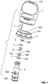
FIG. 1 is an exploded view of an atomizer according to one embodiment of the disclosure; -
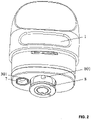
FIG. 2 is a perspective view of an atomizer according to one embodiment of the disclosure; -
FIG. 3 is a cross-sectional view of an atomizer according to one embodiment of the disclosure; -
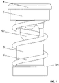
FIG. 4 is a perspective view of a combination of aliquid injection member 7 and an elastic member according to one embodiment of the disclosure; -
FIG. 5 is a cross-sectional view of a combination of aliquid injection member 7 and an elastic member according to one embodiment of the disclosure; -
FIG. 6 is a perspective view of aliquid injection member 7 according to one embodiment of the disclosure; and -
FIG. 7 is a cross-sectional view including arrows showing the direction of air flow in an atomizer according to one embodiment of the disclosure. - In the drawings, the following reference numbers are used: 1. Housing; 2. Supporting member; 3. Sealing member; 4. Plug; 5. Seal ring; 6. Elastic member; 7. Liquid injection member; 8. Atomizing core; 101. Mouthpiece; 102. E-liquid chamber; 103. Air duct; 301. First e-liquid channel; 302. Second through
hole 302; 303. First flange; 400. Cap; 401. Column; 701. Second e-liquid channel; 702. Second e-liquid inlet; 703. Narrow-necked portion; 704. Second flange; 801. Second e-liquid inlet; 802. Air inlet; 803. Heating element; 804. Heating chamber. - Referring to
FIGS. 1-3 , an atomizer comprises ahousing 1. The housing comprises an opening functioning as amouthpiece 101. Themouthpiece 101 extends internally to form anair duct 103. Ane-liquid chamber 102 is defined by an inner wall of the housing and an outer wall of theair duct 103. - The atomizer further comprises an
e-liquid injection member 7 through which the e-liquid can flow into thee-liquid chamber 102. Thee-liquid injection member 7 comprises at least onefirst e-liquid inlet 702. Thee-liquid injection member 7 is movable to a first position in which the at least onefirst e-liquid inlet 702 enters thee-liquid chamber 102. Thee-liquid injection member 7 is further movable to a second position in which the at least onefirst e-liquid inlet 702 exits thee-liquid chamber 102. Thee-liquid injection member 7 is movable between the first position and the second position. Preferably, thee-liquid injection member 7 comprises twofirst e-liquid inlets 702, which provides a fast supply of the e-liquid and prevents leakage of the e-liquid. - Referring to
FIG. 6 , the at least onefirst e-liquid inlet 702 is in the shape of acone 700 with a wider outside opening and a narrow inside opening at both ends, thus preventing leakage of the e-liquid. - The housing further comprises a first
e-liquid channel 301 communicating with thee-liquid chamber 102. The -liquid injection member 7 is disposed in the firste-liquid channel 301 so as to move up and down the firste-liquid channel 301. The firste-liquid channel 301 is disposed along a horizontal, a vertical, or an oblique direction with respect to the atomizer. - In certain examples, the
e-liquid chamber 102 and the firste-liquid channel 301 are disposed in thehousing 1 and separated from each other. In certain examples, the firste-liquid channel 301 is formed in other components of the atomizer. In certain examples, the atomizer further comprises a sealingmember 3 disposed in thee-liquid chamber 102. The firste-liquid channel 301 is disposed in the sealingmember 3. - In certain examples, the
e-liquid injection member 7 comprises a proximal end toward thee-liquid chamber 102. The firste-liquid channel 301 comprises an outlet communicating with thee-liquid chamber 102. As thee-liquid injection member 7 moves, the proximal end enters or exits thee-liquid chamber 102. When thee-liquid injection member 7 moves to the first position, the at least one firste-liquid inlet 702 extends into thee-liquid chamber 102. When thee-liquid injection member 7 moves to the second position, the at least one firste-liquid inlet 702 returns back to the firste-liquid channel 301. - In certain examples, a channel is formed between an inner wall of the first
e-liquid channel 301 and an outer wall of thee-liquid injection member 7. The atomizer further comprises aseal ring 5 disposed around the proximal end of thee-liquid injection member 7. When thee-liquid injection member 7 is moved to the first position, the seal ring moves as well, thus communicating channel with thee-liquid chamber 102. The e-liquid flows through the at least one firste-liquid inlet 702 into the channel and enters thee-liquid chamber 102. After filling of the e-liquid chamber is complete, thee-liquid injection member 7 is moved back to the second position and the channel is sealed by theseal ring 5, thus separating the at least one firste-liquid inlet 702 and thee-liquid chamber 102 from each other. - In certain examples, the
e-liquid chamber 102 and the firste-liquid channel 301 are separated by a partition and disposed in parallel. One side of the partition functions as an inner wall of thee-liquid chamber 102 and the other side of the partition functions as the inner wall of the firste-liquid channel 301. The partition comprises one first through hole. When thee-liquid injection member 7 is moved to the first position, the at least one firste-liquid inlet 702 corresponds to the position of the first through hole, thus communicating the at least one firste-liquid inlet 702 with thee-liquid chamber 102. After filling of the e-liquid chamber is complete, thee-liquid injection member 7 is moved to the second position to ensure that the at least one firste-liquid inlet 702 is sealed by the inner wall of the firste-liquid channel 301. - The
e-liquid injection member 7 further comprises a seconde-liquid channel 701 communicating with the at least one firste-liquid inlet 702. The proximal end of thee-liquid injection member 7 is sealed. The e-liquid flows through the seconde-liquid channel 701 into the at least one firste-liquid inlet 702 and enters thee-liquid chamber 102. - The proximal end of the
e-liquid injection member 7 is concave to form a narrow-necked portion 703. Theseal ring 5 is sleeving the narrow-necked portion 703. The atomizer further comprises aplug 4 disposed in a top part of the narrow-necked portion 703. When thee-liquid injection member 7 is moved back to the firste-liquid channel 301, theseal ring 5 abuts against an upper opening of the seconde-liquid channel 701 to ensure that the firste-liquid channel 301 is sealed, thus preventing the e-liquid from flowing out of the atomizer. - Referring to
FIG. 5 , theplug 4 comprises acap 400 and acolumn 401 formed integrally with thecap 400. One end of thecolumn 401 is connected to thecap 400 and the other end of thecolumn 401 is disposed into the seconde-liquid channel 701. Theseal ring 5 is fixedly disposed between thecap 400 and the upper opening of the seconde-liquid channel 701. - In certain examples, the first
e-liquid channel 301 is disposed in the sealingmember 3. In certain examples, the firste-liquid channel 301 is disposed in thehousing 1; specifically, thehousing 1 comprises an e-liquid injection tube disposed internally and functioning as the firste-liquid channel 301. - The sealing
member 3 comprises a second throughhole 302. The atomizer further comprises anatomizing core 8 disposed into the second throughhole 302. Theatomizing core 8 comprises aheating chamber 804. The atomizer further comprises aheating element 803 disposed in theheating chamber 804. Theheating core 8 comprises an outer wall comprising at least one seconde-liquid inlet 801 and at least oneair inlet 802. The at least one seconde-liquid inlet 801 corresponds with the position of thee-liquid chamber 102. One end of theatomizing core 8 is disposed through the second throughhole 302 into thee-liquid chamber 102 to communicate with theair duct 103. The at least oneair inlet 802 is exposed outside the second throughhole 302. The at least one seconde-liquid inlet 801 communicates with theheating chamber 804. External air flows through the at least oneair inlet 802 into theheating chamber 804, causing theheating element 803 to atomize the e-liquid. The smoke generated flows through theair duct 103 and themouthpiece 101 successively and is inhaled by a user. - Referring to
FIGS. 1-6 , the atomizer comprises ahousing 1, a supportingmember 2, a sealingmember 3, aplug 4, aseal ring 5, anelastic member 6, ane-liquid injection member 7, and anatomizing core 8. Thehousing 1 comprises ane-liquid chamber 102 configured to store e-liquid. Thee-liquid injection member 7 comprises an outer wall comprising two firste-liquid inlets 702. The housing comprises an opening functioning as amouthpiece 101. The sealingmember 3 is disposed in a bottom part of thehousing 1 so as to seal thee-liquid chamber 102. The sealingmember 3 comprises a firste-liquid channel 301 and a second throughhole 302. Theatomizing core 8 is disposed through the second throughhole 302 and extends into theheating chamber 804. Thee-liquid injection member 7 is disposed into the firste-liquid channel 301. The firste-liquid channel 301 communicates with thee-liquid chamber 102 and the two firste-liquid inlets 702 so that the e-liquid can flow through the two firste-liquid inlets 702 into the firste-liquid channel 301 and enters thee-liquid chamber 102. The sealingmember 3 comprises a top part recessed to form a concave portion. The supportingmember 2 is disposed in the concave portion so as to prevent deformation of the sealingmember 3 during injection molding. The firste-liquid channel 301 comprises an inner wall comprising afirst flange 303. Thefirst flange 303 is configured to support and prevent changes in the position of a top portion of theelastic member 6. Theelastic member 6 is in the form of a spring or an elastic piece and is disposed around thee-liquid injection member 7. An upper portion of thee-liquid injection member 7 is concave to form a narrow-necked portion 703. Theseal ring 5 is sleeving the narrow-necked portion 703 to seal an upper opening of the seconde-liquid channel 701. The narrow-necked portion 703 is disposed through thefirst flange 303. Thee-liquid injection member 7 comprises a lower portion comprising asecond flange 704 configured to limit changes in the position of a bottom portion of theelastic member 6. Thee-liquid injection member 7 comprises a seconde-liquid channel 701 communicating with the two firste-liquid inlets 702. The e-liquid is injected through the seconde-liquid channel 701 into the two firste-liquid inlets 702 and enters thee-liquid chamber 102. The top portion and the bottom portion of theelastic member 6 abut against thefirst flange 303 and thesecond flange 704, respectively. Thefirst flange 303 and thesecond flange 704 are configured to limit changes in the position of theelastic member 6. Theplug 4 comprises acap 400 and acolumn 401 formed integrally with thecap 400. Theplug 4 is disposed into the seconde-liquid channel 701. Theseal ring 5 is fixedly disposed between thecap 400 and the upper opening of the seconde-liquid channel 701. A channel is formed between the inner wall of the firste-liquid channel 301 and the outer wall of thee-liquid injection member 7. Theelastic member 6 is disposed in the channel. - When the
e-liquid injection member 7 is pressed, theelastic member 6 deforms, causing thee-liquid injection member 7 to enter thee-liquid chamber 102. Theseal ring 5 is separated from the upper opening of the seconde-liquid channel 701 so that the firste-liquid channel 301 communicate with thee-liquid chamber 102. The e-liquid flows through the seconde-liquid channel 701, the two firste-liquid inlets 702, and the channel successively, and enters thee-liquid chamber 102. Thehousing 1 comprises anair duct 103 configured for air conduction and smoke emission. Themouthpiece 101 is configured to communicate with a top opening of theair duct 103 to ensure that the smoke can be inhaled by a user. An upper end of theatomizing core 8 is disposed through the second throughhole 302 into thee-liquid chamber 102 to communicate with theair duct 103. A lower part is exposed outside the second throughhole 302. Theatomizing core 8 comprises aheating chamber 804. The atomizer further comprises aheating element 803 disposed in theheating chamber 804. Theheating core 8 comprises an outer wall comprising four seconde-liquid inlet 801 and oneair inlet 802. The four seconde-liquid inlet 801 are disposed in thee-liquid chamber 102 and theair inlet 802 is exposed outside the second throughhole 302. The seconde-liquid inlet 801 communicates with theheating chamber 804. -
FIG. 7 is a cross-sectional view including arrows showing the direction of the air flow in the atomizer. External air flows through theair inlet 802 and enters theheating chamber 804, causing theheating element 803 to atomize the e-liquid. The smoke generated flows through theair duct 103 into themouthpiece 101 and is inhaled by a user. - A second example is similar to Example 1, except for the following specific differences: when the
e-liquid injection member 7 is moved to the first position, the two firste-liquid inlets 702 enters thee-liquid chamber 102. When thee-liquid injection member 7 is moved to the second position, the two firste-liquid inlets 702 exits thee-liquid chamber 102 and sealed by the inner wall of the firste-liquid channel 301. The outer wall of thee-liquid injection member 7 comprises a male thread and the inner wall of the firste-liquid channel 301 comprises a female thread. The male thread is screwed to the female thread so that thee-liquid injection member 7 is disposed into the firste-liquid channel 301. Thee-liquid injection member 7 is movable between the first position and the second position through threads. Theliquid injection member 7 further comprises a handle. The handle is turned, causing thee-liquid injection member 7 to rotate. Or an inner wall of the seconde-liquid channel 701 is knurled or frosted, thus increasing friction in the seconde-liquid channel 701. The seconde-liquid channel 701 can be rotated by a finger. - Athird example is similar to Example 2, except for the following specific differences: when the
e-liquid injection member 7 is moved to the first position, the two firste-liquid inlets 702 enters thee-liquid chamber 102. When thee-liquid injection member 7 is moved to the second position, the two firste-liquid inlets 702 exits thee-liquid chamber 102 and is sealed by the inner wall of the firste-liquid channel 301. The outer wall of thee-liquid injection member 7 comprises a female buckle. The inner wall of the firste-liquid channel 301 comprises a male buckle fitted to the male buckle. When thee-liquid injection member 7 is moved toward thee-liquid chamber 102, the male buckle is separated from the female buckle. When thee-liquid injection member 7 is moved back to the firste-liquid channel 301, the female buckle is fitted to the male buckle. Thee-liquid injection member 7 further comprises a handle. The handle is turned, causing thee-liquid injection member 7 to rotate.
Claims (16)
- An atomizer, comprising a housing comprising an e-liquid chamber, the e-liquid chamber is equipped with an e-liquid injection member, wherein the e-liquid injection member comprises at least one first e-liquid inlet; the e-liquid injection member is movable between a first position and a second position; in the first position, the at least one first e-liquid inlet communicates with the e-liquid chamber; and in the second position, the at least one first e-liquid inlet is not in communication with the e-liquid chamber.
- The atomizer of claim 1, wherein the housing further comprises a first e-liquid channel communicating with the e-liquid chamber; the e-liquid injection member is disposed into the first e-liquid channel and is movable in the first e-liquid channel; the e-liquid injection member further comprises a proximal end toward the e-liquid chamber.
- The atomizer of claim 2, wherein the e-liquid injection member comprises a second e-liquid channel communicating with the at least one first e-liquid inlet; and the proximal end of the e-liquid injection member is sealed.
- The atomizer of claim 2, whereinthe first e-liquid channel comprises an inner wall comprising a first flange; the e-liquid injection member comprises an outer wall comprising a second flange; the atomizer further comprises an elastic member disposed around the e-liquid injection member; a top portion and a bottom portion of the elastic member abut against the first flange and the second flange, respectively; anda channel is formed between the inner wall of the first e-liquid channel and the outer wall of the e-liquid injection member, the is disposed in the channel.
- The atomizer of claim 4, wherein in the first position, at least a part of the at least one first e-liquid inlet moves into the e-liquid chamber when the elastic member is compressed by the e-liquid injection member; or in the first position, the at least one first e-liquid inlet is not in the e-liquid chamber when the elastic member is compressed by the e-liquid injection member, the at least one first e-liquid inlet communicates with the e-liquid chamber through the channel.
- The atomizer of claim 2, wherein in the first position, at least a part of the at least one first e-liquid inlet moves into the e-liquid chamber.
- The atomizer of claim 6, wherein the outer wall of the e-liquid injection member comprises a male thread and the inner wall of the first e-liquid channel comprises a female thread; the e-liquid injection member is secured within the first e-liquid channel through the cooperation of the male thread and the female thread; and the e-liquid injection member is movable between the first position and the second position when the male thread moves with respect to the female thread.
- The atomizer of claim 6, wherein one of the outer wall of the e-liquid injection member and the inner wall of the first e-liquid channel comprises a female buckle, and the other comprises a male buckle fitted to the female buckle.
- The atomizer of claim 3, wherein the proximal end of the e-liquid injection member is concave to form a narrow-necked portion; the atomizer further comprises a seal ring sleeving the narrow-necked portion; the atomizer further comprises a plug disposed in a top part of the narrow-necked portion; when the e-liquid injection member is moved to the second position, the channel is sealed by the seal ring.
- The atomizer of claim 9, wherein the plug comprises a cap and a column; one end of the column is connected to the cap and the other end of the column is disposed into the second e-liquid channel; the seal ring is fixedly disposed between the cap and an upper opening of the second e-liquid channel.
- The atomizer of claim 1, wherein the at least one first e-liquid inlet is in the shape of a cone with a wider outside opening and a narrow inside opening at both ends.
- The atomizer of claim 2, wherein the atomizer further comprises a sealing member disposed in one end of the housing; and the first e-liquid channel is disposed in the sealing member.
- The atomizer of claim 12, wherein the sealing member comprises a through hole; the atomizer further comprises an atomizing core; and one end of the atomizing core is disposed through the through hole and extends into the e-liquid chamber, and the other end of the atomizing core is exposed outside the through hole.
- The atomizer of claim 13, wherein the atomizing core comprises a heating chamber; the atomizer further comprises a heating element disposed in the heating chamber, the heating core comprises an outer wall comprising at least one air inlet, the at least one air inlet is exposed outside the through hole and communicates with the heating chamber.
- The atomizer of claim 13, wherein the outer wall further comprises at least one second e-liquid inlet, and the at least one second e-liquid inlet corresponds to the position of the e-liquid chamber.
- The atomizer of claim 1, wherein the housing comprises an opening and side walls surrounding the opening; the side walls extend internally to form an air duct for air conduction and smoke emission; the atomizing core is disposed through the through hole and extends into the heating chamber to communicate with the air duct.
Applications Claiming Priority (2)
| Application Number | Priority Date | Filing Date | Title |
|---|---|---|---|
| CN202110803266.XA CN113455717A (en) | 2021-07-15 | 2021-07-15 | Convenient atomizer of oiling |
| CN202121613524.XU CN216019098U (en) | 2021-07-15 | 2021-07-15 | Convenient atomizer of oiling |
Publications (2)
| Publication Number | Publication Date |
|---|---|
| EP4118987A1 true EP4118987A1 (en) | 2023-01-18 |
| EP4118987B1 EP4118987B1 (en) | 2025-12-03 |
Family
ID=78844671
Family Applications (1)
| Application Number | Title | Priority Date | Filing Date |
|---|---|---|---|
| EP21000348.9A Active EP4118987B1 (en) | 2021-07-15 | 2021-12-10 | Atomizer |
Country Status (6)
| Country | Link |
|---|---|
| EP (1) | EP4118987B1 (en) |
| JP (1) | JP7303917B2 (en) |
| KR (1) | KR20230012406A (en) |
| CA (1) | CA3142816C (en) |
| MY (1) | MY209040A (en) |
| WO (1) | WO2023284338A1 (en) |
Citations (5)
| Publication number | Priority date | Publication date | Assignee | Title |
|---|---|---|---|---|
| WO2010073018A1 (en) * | 2008-12-23 | 2010-07-01 | Kind Consumer Limited | A simulated cigarette device |
| WO2014155089A1 (en) * | 2013-03-26 | 2014-10-02 | Kind Consumer Limited | A pressurised refill canister with an outlet valve |
| EP3143884A2 (en) * | 2015-09-15 | 2017-03-22 | Fontem Holdings 1 B.V. | Electronic smoking device with refillable liquid reservoir |
| EP3498114A1 (en) * | 2017-12-18 | 2019-06-19 | Fontem Holdings 1 B.V. | Electronic smoking device with liquid duct |
| EP3556233A1 (en) * | 2018-04-17 | 2019-10-23 | Shenzhen Smoore Technology Limited | Atomization device and electronic cigarette with the same |
Family Cites Families (18)
| Publication number | Priority date | Publication date | Assignee | Title |
|---|---|---|---|---|
| JPS58106269A (en) * | 1981-12-21 | 1983-06-24 | Daikin Ind Ltd | Valve device |
| JPS60208671A (en) * | 1984-04-02 | 1985-10-21 | Babcock Hitachi Kk | Adjusting valve |
| JPH01242881A (en) * | 1988-03-24 | 1989-09-27 | Toshiba Corp | Valve device |
| JPH0741147U (en) * | 1993-12-24 | 1995-07-21 | 勝 朝良 | Valve mechanism such as fire hydrant |
| JP2001020329A (en) | 1999-07-06 | 2001-01-23 | Komei Seisakusho:Kk | Multifunctional stopcock for water supply |
| JP2008240741A (en) | 2007-03-23 | 2008-10-09 | Fujita Giken Kogyo Kk | Check valve device |
| JP2011094705A (en) | 2009-10-29 | 2011-05-12 | Mitsubishi Electric Corp | Check valve and hot water storage type water heater |
| KR20120094565A (en) * | 2011-02-17 | 2012-08-27 | 휘 춘 장 | Electronic cigarette |
| WO2015051538A1 (en) * | 2013-10-11 | 2015-04-16 | 吉瑞高新科技股份有限公司 | Atomizer, electronic cigarette and method for assembling electronic cigarette |
| CN208425512U (en) * | 2016-04-28 | 2019-01-25 | 惠州市吉瑞科技有限公司深圳分公司 | an atomizing component |
| WO2019121684A1 (en) | 2017-12-18 | 2019-06-27 | Fontem Holdings 1 B.V. | Electronic smoking device with liquid filling valve |
| CN108323822B (en) * | 2018-04-17 | 2023-09-12 | 深圳麦克韦尔科技有限公司 | Atomizing device and electronic cigarette |
| CN209436265U (en) | 2018-11-28 | 2019-09-27 | 深圳市爱卓依科技有限公司 | Oiling smoke grenade structure |
| CN212414722U (en) * | 2020-04-21 | 2021-01-29 | 深圳市沁园春科技有限公司 | Lock oil atomizing device and electronic atomizer |
| CN212590251U (en) * | 2020-05-29 | 2021-02-26 | 深圳市卓力能技术股份有限公司 | Atomizer and electronic atomization device |
| CN112586807B (en) | 2020-12-29 | 2021-07-13 | 深圳市爱乐米科技有限公司 | Electronic cigarette |
| CN113455717A (en) * | 2021-07-15 | 2021-10-01 | 深圳易佳特科技有限公司 | Convenient atomizer of oiling |
| CN216019098U (en) * | 2021-07-15 | 2022-03-15 | 深圳易佳特科技有限公司 | Convenient atomizer of oiling |
-
2021
- 2021-12-10 EP EP21000348.9A patent/EP4118987B1/en active Active
- 2021-12-17 CA CA3142816A patent/CA3142816C/en active Active
- 2021-12-28 MY MYPI2021007809A patent/MY209040A/en unknown
-
2022
- 2022-02-21 JP JP2022025120A patent/JP7303917B2/en active Active
- 2022-03-04 KR KR1020220028367A patent/KR20230012406A/en not_active Ceased
- 2022-04-07 WO PCT/CN2022/085523 patent/WO2023284338A1/en not_active Ceased
Patent Citations (5)
| Publication number | Priority date | Publication date | Assignee | Title |
|---|---|---|---|---|
| WO2010073018A1 (en) * | 2008-12-23 | 2010-07-01 | Kind Consumer Limited | A simulated cigarette device |
| WO2014155089A1 (en) * | 2013-03-26 | 2014-10-02 | Kind Consumer Limited | A pressurised refill canister with an outlet valve |
| EP3143884A2 (en) * | 2015-09-15 | 2017-03-22 | Fontem Holdings 1 B.V. | Electronic smoking device with refillable liquid reservoir |
| EP3498114A1 (en) * | 2017-12-18 | 2019-06-19 | Fontem Holdings 1 B.V. | Electronic smoking device with liquid duct |
| EP3556233A1 (en) * | 2018-04-17 | 2019-10-23 | Shenzhen Smoore Technology Limited | Atomization device and electronic cigarette with the same |
Also Published As
| Publication number | Publication date |
|---|---|
| JP7303917B2 (en) | 2023-07-05 |
| JP2023013919A (en) | 2023-01-26 |
| WO2023284338A1 (en) | 2023-01-19 |
| CA3142816A1 (en) | 2023-01-15 |
| CA3142816C (en) | 2026-03-03 |
| MY209040A (en) | 2025-06-17 |
| EP4118987B1 (en) | 2025-12-03 |
| KR20230012406A (en) | 2023-01-26 |
Similar Documents
| Publication | Publication Date | Title |
|---|---|---|
| US10492537B2 (en) | Atomizer head, atomizer and electronic cigarette containing the atomizer | |
| CN210611016U (en) | Electronic atomization device and atomizer thereof | |
| CN105035506B (en) | Spring external pump core and its application method | |
| CN110881689B (en) | Electronic atomization device and atomizer thereof | |
| KR20210098468A (en) | Aerosol inhaler mouthpiece with valve | |
| US1655678A (en) | Atomizer | |
| WO2016202303A1 (en) | Atomiser and aerosol generating apparatus | |
| CN109922678A (en) | Electrical smoking device with the liquid storage device that can be refilled | |
| HU221949B1 (en) | Trigger pump liquid dispenser | |
| CN213549686U (en) | Atomizer and electronic atomization device | |
| WO2018024215A1 (en) | Atomizer and electronic cigarette comprising same | |
| US5405060A (en) | Liquid spray device | |
| JP2016512468A (en) | Refillable device for stuffing and dispensing fluid products | |
| CN204916563U (en) | Pump core | |
| US3018971A (en) | Atomizer | |
| JP2008535651A (en) | Dosing head for dispensing fluid from a container | |
| US12502683B2 (en) | Liquid dispenser | |
| CN211379638U (en) | Electronic atomization device and atomizer thereof | |
| CA3142816C (en) | Atomizer | |
| KR102573274B1 (en) | Tubeless dispenser container | |
| BRPI0401658B1 (en) | pump intended to be fixed in a container, and, container | |
| GB2231096A (en) | Pumping mechanism for dispensing lotion in bottle/container | |
| CN219962174U (en) | Exhaust apparatus and perfume partial shipment bottle | |
| CN224165709U (en) | Electronic atomizer | |
| TWI773546B (en) | Bagless gas canister for gas nailer |
Legal Events
| Date | Code | Title | Description |
|---|---|---|---|
| PUAI | Public reference made under article 153(3) epc to a published international application that has entered the european phase |
Free format text: ORIGINAL CODE: 0009012 |
|
| STAA | Information on the status of an ep patent application or granted ep patent |
Free format text: STATUS: THE APPLICATION HAS BEEN PUBLISHED |
|
| AK | Designated contracting states |
Kind code of ref document: A1 Designated state(s): AL AT BE BG CH CY CZ DE DK EE ES FI FR GB GR HR HU IE IS IT LI LT LU LV MC MK MT NL NO PL PT RO RS SE SI SK SM TR |
|
| STAA | Information on the status of an ep patent application or granted ep patent |
Free format text: STATUS: REQUEST FOR EXAMINATION WAS MADE |
|
| 17P | Request for examination filed |
Effective date: 20230704 |
|
| RBV | Designated contracting states (corrected) |
Designated state(s): AL AT BE BG CH CY CZ DE DK EE ES FI FR GB GR HR HU IE IS IT LI LT LU LV MC MK MT NL NO PL PT RO RS SE SI SK SM TR |
|
| GRAP | Despatch of communication of intention to grant a patent |
Free format text: ORIGINAL CODE: EPIDOSNIGR1 |
|
| STAA | Information on the status of an ep patent application or granted ep patent |
Free format text: STATUS: GRANT OF PATENT IS INTENDED |
|
| RIC1 | Information provided on ipc code assigned before grant |
Ipc: A24F 40/10 20200101ALN20250324BHEP Ipc: A24F 40/485 20200101AFI20250324BHEP |
|
| INTG | Intention to grant announced |
Effective date: 20250422 |
|
| GRAS | Grant fee paid |
Free format text: ORIGINAL CODE: EPIDOSNIGR3 |
|
| GRAJ | Information related to disapproval of communication of intention to grant by the applicant or resumption of examination proceedings by the epo deleted |
Free format text: ORIGINAL CODE: EPIDOSDIGR1 |
|
| GRAL | Information related to payment of fee for publishing/printing deleted |
Free format text: ORIGINAL CODE: EPIDOSDIGR3 |
|
| STAA | Information on the status of an ep patent application or granted ep patent |
Free format text: STATUS: REQUEST FOR EXAMINATION WAS MADE |
|
| GRAP | Despatch of communication of intention to grant a patent |
Free format text: ORIGINAL CODE: EPIDOSNIGR1 |
|
| STAA | Information on the status of an ep patent application or granted ep patent |
Free format text: STATUS: GRANT OF PATENT IS INTENDED |
|
| INTC | Intention to grant announced (deleted) | ||
| RIC1 | Information provided on ipc code assigned before grant |
Ipc: A24F 40/485 20200101AFI20250908BHEP Ipc: A24F 40/10 20200101ALN20250908BHEP |
|
| INTG | Intention to grant announced |
Effective date: 20250925 |
|
| GRAA | (expected) grant |
Free format text: ORIGINAL CODE: 0009210 |
|
| STAA | Information on the status of an ep patent application or granted ep patent |
Free format text: STATUS: THE PATENT HAS BEEN GRANTED |
|
| AK | Designated contracting states |
Kind code of ref document: B1 Designated state(s): AL AT BE BG CH CY CZ DE DK EE ES FI FR GB GR HR HU IE IS IT LI LT LU LV MC MK MT NL NO PL PT RO RS SE SI SK SM TR |
|
| REG | Reference to a national code |
Ref country code: CH Ref legal event code: F10 Free format text: ST27 STATUS EVENT CODE: U-0-0-F10-F00 (AS PROVIDED BY THE NATIONAL OFFICE) Effective date: 20251203 Ref country code: GB Ref legal event code: FG4D |
|
| REG | Reference to a national code |
Ref country code: DE Ref legal event code: R096 Ref document number: 602021043433 Country of ref document: DE |
|
| REG | Reference to a national code |
Ref country code: IE Ref legal event code: FG4D |
|
| PGFP | Annual fee paid to national office [announced via postgrant information from national office to epo] |
Ref country code: AT Payment date: 20260113 Year of fee payment: 5 |
|
| REG | Reference to a national code |
Ref country code: NL Ref legal event code: MP Effective date: 20251203 |
|
| PGFP | Annual fee paid to national office [announced via postgrant information from national office to epo] |
Ref country code: GB Payment date: 20260113 Year of fee payment: 5 |
|
| PG25 | Lapsed in a contracting state [announced via postgrant information from national office to epo] |
Ref country code: ES Free format text: LAPSE BECAUSE OF FAILURE TO SUBMIT A TRANSLATION OF THE DESCRIPTION OR TO PAY THE FEE WITHIN THE PRESCRIBED TIME-LIMIT Effective date: 20251203 |
|
| REG | Reference to a national code |
Ref country code: LT Ref legal event code: MG9D |
|
| PG25 | Lapsed in a contracting state [announced via postgrant information from national office to epo] |
Ref country code: NO Free format text: LAPSE BECAUSE OF FAILURE TO SUBMIT A TRANSLATION OF THE DESCRIPTION OR TO PAY THE FEE WITHIN THE PRESCRIBED TIME-LIMIT Effective date: 20260303 |
|
| PG25 | Lapsed in a contracting state [announced via postgrant information from national office to epo] |
Ref country code: FI Free format text: LAPSE BECAUSE OF FAILURE TO SUBMIT A TRANSLATION OF THE DESCRIPTION OR TO PAY THE FEE WITHIN THE PRESCRIBED TIME-LIMIT Effective date: 20251203 Ref country code: HR Free format text: LAPSE BECAUSE OF FAILURE TO SUBMIT A TRANSLATION OF THE DESCRIPTION OR TO PAY THE FEE WITHIN THE PRESCRIBED TIME-LIMIT Effective date: 20251203 |
|
| PG25 | Lapsed in a contracting state [announced via postgrant information from national office to epo] |
Ref country code: RS Free format text: LAPSE BECAUSE OF FAILURE TO SUBMIT A TRANSLATION OF THE DESCRIPTION OR TO PAY THE FEE WITHIN THE PRESCRIBED TIME-LIMIT Effective date: 20260303 |
|
| PG25 | Lapsed in a contracting state [announced via postgrant information from national office to epo] |
Ref country code: PL Free format text: LAPSE BECAUSE OF FAILURE TO SUBMIT A TRANSLATION OF THE DESCRIPTION OR TO PAY THE FEE WITHIN THE PRESCRIBED TIME-LIMIT Effective date: 20251203 |
|
| PG25 | Lapsed in a contracting state [announced via postgrant information from national office to epo] |
Ref country code: LV Free format text: LAPSE BECAUSE OF FAILURE TO SUBMIT A TRANSLATION OF THE DESCRIPTION OR TO PAY THE FEE WITHIN THE PRESCRIBED TIME-LIMIT Effective date: 20251203 |
|
| PG25 | Lapsed in a contracting state [announced via postgrant information from national office to epo] |
Ref country code: BG Free format text: LAPSE BECAUSE OF FAILURE TO SUBMIT A TRANSLATION OF THE DESCRIPTION OR TO PAY THE FEE WITHIN THE PRESCRIBED TIME-LIMIT Effective date: 20251203 |
|
| REG | Reference to a national code |
Ref country code: AT Ref legal event code: MK05 Ref document number: 1862639 Country of ref document: AT Kind code of ref document: T Effective date: 20251203 |
|
| PG25 | Lapsed in a contracting state [announced via postgrant information from national office to epo] |
Ref country code: NL Free format text: LAPSE BECAUSE OF FAILURE TO SUBMIT A TRANSLATION OF THE DESCRIPTION OR TO PAY THE FEE WITHIN THE PRESCRIBED TIME-LIMIT Effective date: 20251203 |
|
| PG25 | Lapsed in a contracting state [announced via postgrant information from national office to epo] |
Ref country code: LT Free format text: LAPSE BECAUSE OF FAILURE TO SUBMIT A TRANSLATION OF THE DESCRIPTION OR TO PAY THE FEE WITHIN THE PRESCRIBED TIME-LIMIT Effective date: 20251203 |
|
| REG | Reference to a national code |
Ref country code: DE Ref legal event code: R119 Ref document number: 602021043433 Country of ref document: DE |
|
| PG25 | Lapsed in a contracting state [announced via postgrant information from national office to epo] |
Ref country code: SM Free format text: LAPSE BECAUSE OF FAILURE TO SUBMIT A TRANSLATION OF THE DESCRIPTION OR TO PAY THE FEE WITHIN THE PRESCRIBED TIME-LIMIT Effective date: 20251203 |
|
| PG25 | Lapsed in a contracting state [announced via postgrant information from national office to epo] |
Ref country code: PT Free format text: LAPSE BECAUSE OF NON-PAYMENT OF DUE FEES Effective date: 20251203 |
|
| PG25 | Lapsed in a contracting state [announced via postgrant information from national office to epo] |
Ref country code: IT Free format text: LAPSE BECAUSE OF FAILURE TO SUBMIT A TRANSLATION OF THE DESCRIPTION OR TO PAY THE FEE WITHIN THE PRESCRIBED TIME-LIMIT Effective date: 20251203 |
|
| PG25 | Lapsed in a contracting state [announced via postgrant information from national office to epo] |
Ref country code: AT Free format text: LAPSE BECAUSE OF FAILURE TO SUBMIT A TRANSLATION OF THE DESCRIPTION OR TO PAY THE FEE WITHIN THE PRESCRIBED TIME-LIMIT Effective date: 20251203 |
|
| PG25 | Lapsed in a contracting state [announced via postgrant information from national office to epo] |
Ref country code: EE Free format text: LAPSE BECAUSE OF FAILURE TO SUBMIT A TRANSLATION OF THE DESCRIPTION OR TO PAY THE FEE WITHIN THE PRESCRIBED TIME-LIMIT Effective date: 20251203 |
|
| PG25 | Lapsed in a contracting state [announced via postgrant information from national office to epo] |
Ref country code: PT Free format text: LAPSE BECAUSE OF FAILURE TO SUBMIT A TRANSLATION OF THE DESCRIPTION OR TO PAY THE FEE WITHIN THE PRESCRIBED TIME-LIMIT Effective date: 20260406 Ref country code: IS Free format text: LAPSE BECAUSE OF FAILURE TO SUBMIT A TRANSLATION OF THE DESCRIPTION OR TO PAY THE FEE WITHIN THE PRESCRIBED TIME-LIMIT Effective date: 20260403 |
|
| PG25 | Lapsed in a contracting state [announced via postgrant information from national office to epo] |
Ref country code: CZ Free format text: LAPSE BECAUSE OF FAILURE TO SUBMIT A TRANSLATION OF THE DESCRIPTION OR TO PAY THE FEE WITHIN THE PRESCRIBED TIME-LIMIT Effective date: 20251203 |
|
| PGFP | Annual fee paid to national office [announced via postgrant information from national office to epo] |
Ref country code: FR Payment date: 20260512 Year of fee payment: 6 |
|
| REG | Reference to a national code |
Ref country code: CH Ref legal event code: H13 Free format text: ST27 STATUS EVENT CODE: U-0-0-H10-H13 (AS PROVIDED BY THE NATIONAL OFFICE) Effective date: 20260723 |
|
| PG25 | Lapsed in a contracting state [announced via postgrant information from national office to epo] |
Ref country code: SK Free format text: LAPSE BECAUSE OF FAILURE TO SUBMIT A TRANSLATION OF THE DESCRIPTION OR TO PAY THE FEE WITHIN THE PRESCRIBED TIME-LIMIT Effective date: 20251203 |
|
| PG25 | Lapsed in a contracting state [announced via postgrant information from national office to epo] |
Ref country code: RO Free format text: LAPSE BECAUSE OF FAILURE TO SUBMIT A TRANSLATION OF THE DESCRIPTION OR TO PAY THE FEE WITHIN THE PRESCRIBED TIME-LIMIT Effective date: 20251203 |
|
| PG25 | Lapsed in a contracting state [announced via postgrant information from national office to epo] |
Ref country code: SE Free format text: LAPSE BECAUSE OF FAILURE TO SUBMIT A TRANSLATION OF THE DESCRIPTION OR TO PAY THE FEE WITHIN THE PRESCRIBED TIME-LIMIT Effective date: 20251203 |