EP4117063B1 - Procédé de traitement des défaillances dans un système de piles à combustible - Google Patents
Procédé de traitement des défaillances dans un système de piles à combustible Download PDFInfo
- Publication number
- EP4117063B1 EP4117063B1 EP21210917.7A EP21210917A EP4117063B1 EP 4117063 B1 EP4117063 B1 EP 4117063B1 EP 21210917 A EP21210917 A EP 21210917A EP 4117063 B1 EP4117063 B1 EP 4117063B1
- Authority
- EP
- European Patent Office
- Prior art keywords
- fuel cell
- cooling
- cooling water
- radiator
- pump
- Prior art date
- Legal status (The legal status is an assumption and is not a legal conclusion. Google has not performed a legal analysis and makes no representation as to the accuracy of the status listed.)
- Active
Links
- 239000000446 fuel Substances 0.000 title claims description 158
- 238000000034 method Methods 0.000 title claims description 9
- 239000000498 cooling water Substances 0.000 claims description 155
- 238000001816 cooling Methods 0.000 claims description 129
- 238000004378 air conditioning Methods 0.000 claims description 34
- 238000010438 heat treatment Methods 0.000 claims description 12
- 230000008859 change Effects 0.000 claims description 6
- 238000004891 communication Methods 0.000 claims description 3
- 239000001257 hydrogen Substances 0.000 description 10
- 229910052739 hydrogen Inorganic materials 0.000 description 10
- 230000006870 function Effects 0.000 description 8
- 150000002500 ions Chemical class 0.000 description 8
- 239000012528 membrane Substances 0.000 description 8
- 238000006243 chemical reaction Methods 0.000 description 7
- UFHFLCQGNIYNRP-UHFFFAOYSA-N Hydrogen Chemical compound [H][H] UFHFLCQGNIYNRP-UHFFFAOYSA-N 0.000 description 6
- 239000007789 gas Substances 0.000 description 5
- 238000004590 computer program Methods 0.000 description 4
- 239000003792 electrolyte Substances 0.000 description 4
- -1 hydrogen ions Chemical class 0.000 description 4
- QVGXLLKOCUKJST-UHFFFAOYSA-N atomic oxygen Chemical compound [O] QVGXLLKOCUKJST-UHFFFAOYSA-N 0.000 description 3
- 230000008901 benefit Effects 0.000 description 3
- 238000013461 design Methods 0.000 description 3
- 239000007800 oxidant agent Substances 0.000 description 3
- 239000001301 oxygen Substances 0.000 description 3
- 229910052760 oxygen Inorganic materials 0.000 description 3
- 239000003054 catalyst Substances 0.000 description 2
- 238000010276 construction Methods 0.000 description 2
- 230000008878 coupling Effects 0.000 description 2
- 238000010168 coupling process Methods 0.000 description 2
- 238000005859 coupling reaction Methods 0.000 description 2
- 230000007423 decrease Effects 0.000 description 2
- 238000010586 diagram Methods 0.000 description 2
- 238000009792 diffusion process Methods 0.000 description 2
- 230000000694 effects Effects 0.000 description 2
- 238000013021 overheating Methods 0.000 description 2
- 238000007789 sealing Methods 0.000 description 2
- XLYOFNOQVPJJNP-UHFFFAOYSA-N water Substances O XLYOFNOQVPJJNP-UHFFFAOYSA-N 0.000 description 2
- 230000002457 bidirectional effect Effects 0.000 description 1
- 238000005341 cation exchange Methods 0.000 description 1
- 239000002826 coolant Substances 0.000 description 1
- 230000007797 corrosion Effects 0.000 description 1
- 238000005260 corrosion Methods 0.000 description 1
- 230000003247 decreasing effect Effects 0.000 description 1
- 230000006866 deterioration Effects 0.000 description 1
- 238000011161 development Methods 0.000 description 1
- 230000018109 developmental process Effects 0.000 description 1
- 230000005611 electricity Effects 0.000 description 1
- 238000005516 engineering process Methods 0.000 description 1
- 230000007613 environmental effect Effects 0.000 description 1
- 238000001914 filtration Methods 0.000 description 1
- 238000007710 freezing Methods 0.000 description 1
- 230000010354 integration Effects 0.000 description 1
- 239000007788 liquid Substances 0.000 description 1
- 230000007246 mechanism Effects 0.000 description 1
- 230000003647 oxidation Effects 0.000 description 1
- 238000007254 oxidation reaction Methods 0.000 description 1
- 238000012545 processing Methods 0.000 description 1
- 238000005086 pumping Methods 0.000 description 1
- 238000006722 reduction reaction Methods 0.000 description 1
- 238000011160 research Methods 0.000 description 1
- 230000000630 rising effect Effects 0.000 description 1
- 239000002210 silicon-based material Substances 0.000 description 1
Images


Classifications
-
- H—ELECTRICITY
- H01—ELECTRIC ELEMENTS
- H01M—PROCESSES OR MEANS, e.g. BATTERIES, FOR THE DIRECT CONVERSION OF CHEMICAL ENERGY INTO ELECTRICAL ENERGY
- H01M8/00—Fuel cells; Manufacture thereof
- H01M8/04—Auxiliary arrangements, e.g. for control of pressure or for circulation of fluids
- H01M8/04298—Processes for controlling fuel cells or fuel cell systems
- H01M8/04313—Processes for controlling fuel cells or fuel cell systems characterised by the detection or assessment of variables; characterised by the detection or assessment of failure or abnormal function
- H01M8/04664—Failure or abnormal function
- H01M8/04686—Failure or abnormal function of auxiliary devices, e.g. batteries, capacitors
-
- H—ELECTRICITY
- H01—ELECTRIC ELEMENTS
- H01M—PROCESSES OR MEANS, e.g. BATTERIES, FOR THE DIRECT CONVERSION OF CHEMICAL ENERGY INTO ELECTRICAL ENERGY
- H01M8/00—Fuel cells; Manufacture thereof
- H01M8/04—Auxiliary arrangements, e.g. for control of pressure or for circulation of fluids
- H01M8/04298—Processes for controlling fuel cells or fuel cell systems
- H01M8/04313—Processes for controlling fuel cells or fuel cell systems characterised by the detection or assessment of variables; characterised by the detection or assessment of failure or abnormal function
- H01M8/0438—Pressure; Ambient pressure; Flow
- H01M8/04417—Pressure; Ambient pressure; Flow of the coolant
-
- H—ELECTRICITY
- H01—ELECTRIC ELEMENTS
- H01M—PROCESSES OR MEANS, e.g. BATTERIES, FOR THE DIRECT CONVERSION OF CHEMICAL ENERGY INTO ELECTRICAL ENERGY
- H01M8/00—Fuel cells; Manufacture thereof
- H01M8/04—Auxiliary arrangements, e.g. for control of pressure or for circulation of fluids
- H01M8/04298—Processes for controlling fuel cells or fuel cell systems
- H01M8/04694—Processes for controlling fuel cells or fuel cell systems characterised by variables to be controlled
- H01M8/04746—Pressure; Flow
- H01M8/04768—Pressure; Flow of the coolant
-
- H—ELECTRICITY
- H01—ELECTRIC ELEMENTS
- H01M—PROCESSES OR MEANS, e.g. BATTERIES, FOR THE DIRECT CONVERSION OF CHEMICAL ENERGY INTO ELECTRICAL ENERGY
- H01M8/00—Fuel cells; Manufacture thereof
- H01M8/04—Auxiliary arrangements, e.g. for control of pressure or for circulation of fluids
- H01M8/04007—Auxiliary arrangements, e.g. for control of pressure or for circulation of fluids related to heat exchange
- H01M8/04029—Heat exchange using liquids
-
- B—PERFORMING OPERATIONS; TRANSPORTING
- B60—VEHICLES IN GENERAL
- B60H—ARRANGEMENTS OF HEATING, COOLING, VENTILATING OR OTHER AIR-TREATING DEVICES SPECIALLY ADAPTED FOR PASSENGER OR GOODS SPACES OF VEHICLES
- B60H1/00—Heating, cooling or ventilating [HVAC] devices
- B60H1/00642—Control systems or circuits; Control members or indication devices for heating, cooling or ventilating devices
- B60H1/00814—Control systems or circuits characterised by their output, for controlling particular components of the heating, cooling or ventilating installation
- B60H1/00821—Control systems or circuits characterised by their output, for controlling particular components of the heating, cooling or ventilating installation the components being ventilating, air admitting or air distributing devices
- B60H1/00864—Ventilators and damper doors
-
- B—PERFORMING OPERATIONS; TRANSPORTING
- B60—VEHICLES IN GENERAL
- B60H—ARRANGEMENTS OF HEATING, COOLING, VENTILATING OR OTHER AIR-TREATING DEVICES SPECIALLY ADAPTED FOR PASSENGER OR GOODS SPACES OF VEHICLES
- B60H1/00—Heating, cooling or ventilating [HVAC] devices
- B60H1/32—Cooling devices
- B60H1/3204—Cooling devices using compression
- B60H1/323—Cooling devices using compression characterised by comprising auxiliary or multiple systems, e.g. plurality of evaporators, or by involving auxiliary cooling devices
-
- H—ELECTRICITY
- H01—ELECTRIC ELEMENTS
- H01M—PROCESSES OR MEANS, e.g. BATTERIES, FOR THE DIRECT CONVERSION OF CHEMICAL ENERGY INTO ELECTRICAL ENERGY
- H01M8/00—Fuel cells; Manufacture thereof
- H01M8/04—Auxiliary arrangements, e.g. for control of pressure or for circulation of fluids
- H01M8/04007—Auxiliary arrangements, e.g. for control of pressure or for circulation of fluids related to heat exchange
- H01M8/04014—Heat exchange using gaseous fluids; Heat exchange by combustion of reactants
-
- H—ELECTRICITY
- H01—ELECTRIC ELEMENTS
- H01M—PROCESSES OR MEANS, e.g. BATTERIES, FOR THE DIRECT CONVERSION OF CHEMICAL ENERGY INTO ELECTRICAL ENERGY
- H01M8/00—Fuel cells; Manufacture thereof
- H01M8/04—Auxiliary arrangements, e.g. for control of pressure or for circulation of fluids
- H01M8/04007—Auxiliary arrangements, e.g. for control of pressure or for circulation of fluids related to heat exchange
- H01M8/04067—Heat exchange or temperature measuring elements, thermal insulation, e.g. heat pipes, heat pumps, fins
- H01M8/04074—Heat exchange unit structures specially adapted for fuel cell
-
- H—ELECTRICITY
- H01—ELECTRIC ELEMENTS
- H01M—PROCESSES OR MEANS, e.g. BATTERIES, FOR THE DIRECT CONVERSION OF CHEMICAL ENERGY INTO ELECTRICAL ENERGY
- H01M8/00—Fuel cells; Manufacture thereof
- H01M8/04—Auxiliary arrangements, e.g. for control of pressure or for circulation of fluids
- H01M8/04298—Processes for controlling fuel cells or fuel cell systems
- H01M8/04313—Processes for controlling fuel cells or fuel cell systems characterised by the detection or assessment of variables; characterised by the detection or assessment of failure or abnormal function
- H01M8/0432—Temperature; Ambient temperature
- H01M8/04358—Temperature; Ambient temperature of the coolant
-
- H—ELECTRICITY
- H01—ELECTRIC ELEMENTS
- H01M—PROCESSES OR MEANS, e.g. BATTERIES, FOR THE DIRECT CONVERSION OF CHEMICAL ENERGY INTO ELECTRICAL ENERGY
- H01M8/00—Fuel cells; Manufacture thereof
- H01M8/04—Auxiliary arrangements, e.g. for control of pressure or for circulation of fluids
- H01M8/04298—Processes for controlling fuel cells or fuel cell systems
- H01M8/04313—Processes for controlling fuel cells or fuel cell systems characterised by the detection or assessment of variables; characterised by the detection or assessment of failure or abnormal function
- H01M8/04537—Electric variables
- H01M8/04604—Power, energy, capacity or load
- H01M8/04626—Power, energy, capacity or load of auxiliary devices, e.g. batteries, capacitors
-
- H—ELECTRICITY
- H01—ELECTRIC ELEMENTS
- H01M—PROCESSES OR MEANS, e.g. BATTERIES, FOR THE DIRECT CONVERSION OF CHEMICAL ENERGY INTO ELECTRICAL ENERGY
- H01M8/00—Fuel cells; Manufacture thereof
- H01M8/04—Auxiliary arrangements, e.g. for control of pressure or for circulation of fluids
- H01M8/04298—Processes for controlling fuel cells or fuel cell systems
- H01M8/04313—Processes for controlling fuel cells or fuel cell systems characterised by the detection or assessment of variables; characterised by the detection or assessment of failure or abnormal function
- H01M8/04664—Failure or abnormal function
- H01M8/04679—Failure or abnormal function of fuel cell stacks
-
- H—ELECTRICITY
- H01—ELECTRIC ELEMENTS
- H01M—PROCESSES OR MEANS, e.g. BATTERIES, FOR THE DIRECT CONVERSION OF CHEMICAL ENERGY INTO ELECTRICAL ENERGY
- H01M8/00—Fuel cells; Manufacture thereof
- H01M8/04—Auxiliary arrangements, e.g. for control of pressure or for circulation of fluids
- H01M8/04298—Processes for controlling fuel cells or fuel cell systems
- H01M8/04694—Processes for controlling fuel cells or fuel cell systems characterised by variables to be controlled
- H01M8/04955—Shut-off or shut-down of fuel cells
-
- H—ELECTRICITY
- H01—ELECTRIC ELEMENTS
- H01M—PROCESSES OR MEANS, e.g. BATTERIES, FOR THE DIRECT CONVERSION OF CHEMICAL ENERGY INTO ELECTRICAL ENERGY
- H01M2250/00—Fuel cells for particular applications; Specific features of fuel cell system
- H01M2250/20—Fuel cells in motive systems, e.g. vehicle, ship, plane
-
- Y—GENERAL TAGGING OF NEW TECHNOLOGICAL DEVELOPMENTS; GENERAL TAGGING OF CROSS-SECTIONAL TECHNOLOGIES SPANNING OVER SEVERAL SECTIONS OF THE IPC; TECHNICAL SUBJECTS COVERED BY FORMER USPC CROSS-REFERENCE ART COLLECTIONS [XRACs] AND DIGESTS
- Y02—TECHNOLOGIES OR APPLICATIONS FOR MITIGATION OR ADAPTATION AGAINST CLIMATE CHANGE
- Y02E—REDUCTION OF GREENHOUSE GAS [GHG] EMISSIONS, RELATED TO ENERGY GENERATION, TRANSMISSION OR DISTRIBUTION
- Y02E60/00—Enabling technologies; Technologies with a potential or indirect contribution to GHG emissions mitigation
- Y02E60/30—Hydrogen technology
- Y02E60/50—Fuel cells
Definitions
- the present disclosure relates to a technology for dealing with a fault in a fuel cell system.
- a fuel cell system may generate electric energy by using a fuel cell stack.
- a fuel cell stack that generates electrical energy
- a fuel supply device that supplies a fuel (hydrogen) to the fuel cell stack
- an air supply device that supplies oxygen in air, which is an oxidizer that is necessary for an electric chemical reaction, to the fuel cell stack
- TMS thermal management system
- the thermal management system is a kind of a cooling device that circulates an anti-freezing liquid that functions as cooling water in a fuel cell system and maintain the fuel cell stack at a proper temperature (for example, 60 to 70°C), and may include a TMS line, in which the cooling water circulates, a reservoir in which the cooling water is stored, a pump that circulates the cooling water, and an ion filter that removes ions included in the cooling water, and a radiator that discharges the heat of the cooling water to the outside.
- the thermal management system may include a heater that heats the cooling water, and an air conditioning system (for example, a heater for heating) that cools and heats an interior of a device (e.g., a vehicle) including the fuel cell system by using the cooling water.
- the thermal management system may maintain a proper temperature of a power electronic component of the vehicle as well as the fuel cell stack.
- KR 101 284 343 B1 and US 2019/0181476 A1 each disclose a fuel cell thermal management system.
- a temperature of cooling water that passes via a fuel cell stack has to be adjusted to a desired temperature, and to achieve this, a radiator has to dissipate heat generated in the fuel cell stack to the air. Accordingly, design of a radiator, a cooling fan, and a pump is considered as an important element in a fuel cell system. For example, when the cooling fan is disabled, the fuel cell stack is overheated.
- a specific vehicle e.g., a construction machine such a forklift truck
- a component such as a cooling fan
- a fuel cell system includes a fuel cell stack, a first cooling line having first cooling water that passes via the fuel cell stack and circulates therein, a first radiator disposed on the first cooling line and that cools the first cooling water, an air conditioning system disposed on a first connection line that forms a heating loop with the first cooling line, a first cooling fan that blows exterior air to the first radiator, a first valve that switches a flow path of the first cooling water to the fuel cell stack or a heater, a second valve that switches the flow path of the first cooling water to the fuel cell stack or the first radiator, a first pump disposed on the first cooling line and that pumps the first cooling water, and a controller connected to the first cooling fan, the first valve, the second valve, and the first pump, and the controller is configured to detect a failure of the first cooling fan, and when a failure of the first cooling fan is detected, to open the first valve such that the first cooling water flows toward the fuel cell stack, to control an RPM of a blower of the air conditioning
- a method for operating a fuel cell system having a fuel cell stack includes detecting a failure of a first cooling fan that blows exterior air to a first radiator, and when a failure of the first cooling fan is detected: opening a first valve such that first cooling water that passes via the fuel cell stack flows toward the fuel cell stack, controlling an RPM of a blower of an air conditioning system to a maximum level, controlling an opening degree of a second valve according to a cooling degree of the first radiator and a cooling degree of the air conditioning system, and controlling an RPM of a first pump that pumps the first cooling water to a maximum level.
- module used in various embodiments of the present disclosure may include a unit configured in a hardware, software, or firmware way, and for example, may be used interchangeably with the terms such as logic, a logic block, a component, or a circuit.
- the module may be an integral component, or a minimum unit or a part which performs one or more functions.
- the module may be implemented in a form of an application-specific integrated circuit (ASIC).
- ASIC application-specific integrated circuit
- Various embodiments of the present disclosure may be implemented by software (e.g., a program) including one or more instructions stored in a storage medium (e.g., an internal memory or an external memory) that may be read by a machine.
- a device may call, among one or more instructions stored in a storage medium, at least one instruction, and may execute the instruction. This allows at least one function to be performed according to the called at least one instruction.
- the one or more instructions may include a code that is made by a compiler or a code that may be executed by an interpreter.
- the storage medium that may be read by a device may be provided in a form of a non-transitory storage medium.
- the 'non-transitory storage medium' means that the storage medium is a tangible device and does not include a signal (e.g., an electromagnetic wave), and with regard to the term, a case, in which data are semi-permanently stored in the storage medium, and a case, in which data are temporarily stored in the storage medium, are not distinguished.
- a signal e.g., an electromagnetic wave
- the methods according to various embodiments of the present disclosure may be provided to be included in a computer program product.
- the computer program product may be traded between a seller and a purchaser.
- the computer program product may be distributed in a form of a storage medium that may be read by a device (e.g., a compact disk read only memory (CD-ROM) or may be distributed (e.g., downloaded or uploaded) through an application store or directly or online between two user devices.
- a device e.g., a compact disk read only memory (CD-ROM)
- CD-ROM compact disk read only memory
- the online distribution at least a portion of the computer program product may be at least temporarily stored in a storage medium, such as a server of a manufacturer, a server of an application store, or a memory of a relay server, which may be read by a device, or temporarily generated.
- elements (e.g., modules or programs) of the above-described elements may include one or a plurality of entities, and some of the plurality of entities may be disposed to be separated from the other elements.
- one or more elements or operations may be omitted or one or more other elements or operations may be added.
- the plurality of elements e.g., modules or programs
- the integrated elements may perform one or more functions of the elements of the plurality of elements in a way that is the same as or similar to the functions performed by the corresponding elements of the plurality of elements before the integration.
- the operations performed by modules, programs, or other elements may be executed sequentially, in parallel, repeatedly, or heuristically, one or more operations may be executed in another sequence or omitted, or one or more other operations may be added.
- FIGS. 1 and 4 illustrate a fuel cell system according to various embodiments.
- a fuel cell system for a vehicle may include a first cooling line 110, in which first cooling water that passes via a fuel cell stack 10 of the vehicle circulates, and a second cooling line, in which second cooling water that passes via power electronic parts of the vehicle circulates.
- the fuel cell system may further include a heat exchanger 300 that exchanges heat between the first cooling water and the second cooling water, but the heat exchanger 300 may be omitted.
- the fuel cell system may include a first connection line 130, a second connection line 150, and a third connection line 140 to form a heating loop (a heating circulation path) with the first cooling line 110 or form a cooling line with the first cooling line 110.
- the first cooling water may be cooled or heated while circulating in the first connection line 130, the second connection line 150, or the third connection line 140.
- the first cooling line 110 as illustrated in FIG. 2A , may form a heating loop with the first connection line 130 and the third connection line 140 to secure a cold start capacity in an initial start condition of the vehicle, and, as illustrated in FIG.
- the first cooling line 110 may secure a start capacity through heat of the fuel cell stack 10.
- the fuel cell stack 10, a first valve 20, a first pump 30, a second valve 40, and the first radiator 60 may be disposed on the first cooling line 110, in which the first cooling water circulates.
- the fuel cell stack 10 may have a structure, in which electricity may be produced through an oxidation/reduction reaction of a fuel (for example, hydrogen) and an oxidizer (for example, air).
- the fuel cell stack 10 may include a membrane electrode assembly (MEA), in which catalyst electrode layers for an electric chemical reaction are attached to opposite sides of a membrane with respect to an electrolyte membrane, through which hydrogen ions travel, a gas diffusion layer (GDL) that uniformly distributes reaction gases and delivers generated electrical energy, a gasket and a coupling mechanism for maintaining a tightness and a proper coupling pressure of the reaction gases and the first cooling water, and a bipolar plate that causes the reaction gases and the first cooling water to flow.
- MEA membrane electrode assembly
- GDL gas diffusion layer
- the hydrogen that is the fuel and the air (oxygen) that is the oxidizer are supplied to an anode and a cathode of the membrane electrode assembly, and the hydrogen may be supplied to the anode and the air may be supplied to the cathode.
- the hydrogen supplied to the anode is decomposed into protons and electrons by a catalyst of the electrode layers provided on opposite sides of the electrolyte membrane, and among them, only the hydrogen ions may be delivered to the cathode after selectively passing through the electrolyte membrane that is a cation exchange membrane, and the electrons may be delivered to the cathode through the gas diffusion layer and the bipolar plate.
- the hydrogen ions supplied through the electrolyte membrane and the electrons delivered through the bipolar plate may meet oxygen in the air supplied to the cathode by an air supply device and may generate a reaction of generating water. Then, the electrons may flow through an external wire due to the flows of the hydrogen ions, and electric currents may be generated due to the flows of the electrons.
- the first valve 20 switches a flow path of the first cooling water to the first connection line 130, in which a heater is disposed, or the fuel cell stack 10 on the first cooling line 110.
- the first valve 20 may be connected to one end of the first pump 30, one end of the first connection line 130, and one end of the fuel cell stack 10 on a first cooling line 20.
- the first valve 20 may include various valve means that may selectively switch the flow path of the first cooling water.
- the first valve 20 may be a 3-way valve.
- the first valve 20 may include a first port 21 connected to the first cooling line 110 such that the first cooling water pumped by a first pump 30 is introduced therethrough, a second port 22 connected to the first cooling line 110 such that the first cooling water that passes through the first valve 20 is introduced into the fuel cell stack 10, and a third port 23 connected to one end of the first connection line 130.
- the second port 22 and the third port 23 of the first valve 20 are opened and closed, the flow path of the first cooling water may be switched to a heater 50 of the first connection line 130 or the fuel cell stack 10.
- the first cooling water may be introduced into the fuel cell stack 10 and to the contrary, when the third port 23 is opened and the second port 22 is closed, the first cooling water may be introduced into the heater 50 through the first connection line 130.
- the first connection line 130 may form a heating loop (a heating circulation path) with the first cooling line 110 to heat the first cooling water.
- the first cooling water that flows along the first connection line 130 may be heated while passing through the heater 50 installed in the first connection line 130.
- One end of the first connection line 130 may be connected to the first cooling line 110 at a first point located between an outlet of the first pump 30 and the fuel cell stack 10, and another end of the first connection line 130 may be connected to the first cooling line 110 at a second point located between an inlet of the first pump 30 and the fuel cell stack 10.
- the inlet of the first pump 30 may be defined as an inlet, through which the first cooling water is introduced into the first pump 30.
- the outlet of the first pump 30 may be defined as an outlet, through which the first cooling water that passed through the first pump 30 is discharged.
- a section between the outlet of the first pump 30 and the fuel cell stack 10 may be defined as a section, in which the first cooling water discharged from the first pump 30 flows to a first cooling water inlet (not illustrated) of the fuel cell stack 10.
- a section between the inlet of the first pump 30 and the fuel cell stack 10 may be defined as a section, in which the first cooling water discharged from a cooling water outlet (not illustrated) of the fuel cell stack 10 flows to the inlet of the first pump 30.
- the first pump 30 may be configured to cause the first cooling water to compulsorily flow.
- the first pump 30 may include various means that may pump the first cooling water, and the kinds and the number of the first pumps 30 are not limited in the present disclosure.
- the second valve 40 may switch the flow path of the first cooling water to the first radiator 60 or the fuel cell stack 10 on the first cooling line 110.
- the second valve 40 may be provided on the first cooling line 110 to be located between the first pump 30 and the first radiator 60, and may be connected to one end of the third connection line 140 and the outlet of the first radiator 60.
- the second valve 40 may include various valve means that may selectively switch the flow path of the first cooling water to the first radiator 60 or the fuel cell stack 10.
- the second valve 40 may be a 4-way valve or a 3-way valve.
- the second valve 40 When the second valve 40 is a 3-way valve, it may include a first port 41 connected to the third connection line 140, a second port 42 connected to the first cooling line 110 such that the first cooling water that passes through the first radiator 60 is introduced therethrough, and a third port 44 connected to the first cooling line 110 such that the first cooling water is introduced into the first pump 30, and when the second valve 40 is a 4-way valve, it may further include a third port 43 connected to one end of the second connection line 150. As the first port 41 or the second port 42 of the second valve 40 is opened and closed, the flow path of the first cooling water may be switched to the first radiator 60 or the fuel cell stack 10.
- the first cooling water when the first port 41 is opened and the second port 42 is closed, the first cooling water is introduced into the fuel cell stack 10 while not passing through the first radiator 60, and to the contrary, when the second port 42 is opened and the first port 41 is closed, the first cooling water may be introduced into the fuel cell stack 10 after passing through the first radiator 60.
- the second connection line 150 may form a heating loop with the first cooling line 110 to heat an air conditioning system (an HVAC system) 90.
- the second connection line 150 may form a loop that heats a heater (not illustrated) for heating an air conditioning system 90.
- One end of the second connection line 150 may be connected to the first cooling line 110 between the first point (the point, at which one end of the first connection line 130 is connected to the first cooling line 110) and the inlet of the fuel cell stack 10, and a portion of the first cooling water may circulate through the second connection line 150.
- Another end of the second connection line 150 may be connected to the first cooling line 110 between the first pump 30 and the second point (the point, at which another end of the first connection line 130 is connected to the first cooling line 110).
- An ion filter 95 that filters ions of the first cooling water that has passed through the air conditioning system 90 may be provided in the second connection line 150. Because electric currents flow the first cooling water so that the fuel cell stack 10 is short-circuited or electric currents flow toward the first cooling water when an electrical conductivity of the first cooling water increases due to corrosion or exudation of the system, the first cooling water has to maintain a low electrical conductivity.
- the ion filter 95 may be configured to remove ions included in the first cooling water to maintain the electrical conductivity of the first cooling water at a specific level or less.
- the first cooling water circulates (a temperature rising loop) via the heater 50 of the first connection line 130 and also circulates along the second connection line 150, whereby filtering (removal of ions included in the first cooling water) may be made possible by the ion filter 95 provided in the second connection line 150 during the cold start. Accordingly, the electrical conductivity of the first cooling water introduced into the fuel cell stack 10 immediately after the cold start may be advantageously maintained at the specific level or less.
- the third connection line 140 may form a cooling loop with the first cooling line 110 to cool the first cooling water.
- one end of the third connection line 140 may be connected to the first cooling line 110 between the first pump 30 and the first radiator 60, and another end of the third connection line 140 may be connected to the first cooling line 110 between the cooling water outlet of the fuel cell stack 10 and the first radiator 60.
- the first radiator 60 is configured to cool the first cooling water.
- the first radiator 60 may have various structures that may cool the first cooling water, and the kinds and structures of the first radiator 60 are not limited or restricted in the present disclosure.
- the first radiator 60 may be connected to a first reservoir 62, in which the first cooling water is stored.
- the fuel cell system may include a first temperature sensor 112 that measures a temperature of the first cooling water between the fuel cell stack 10 and the first point (the first valve 20), a second temperature sensor 114 that measures a temperature of the first cooling water between another end of the first connection line 130 and the first pump 30, and a third temperature sensor 116 that measures a temperature of the cooling water in the heater 50.
- the fuel cell system may control a flow rate of the first cooling water introduced into the fuel cell stack 10 based on the temperatures measured by the first temperature sensor 112, the second temperature sensor 114, and the third temperature sensor 116.
- the flow rate of the introduced first cooling water may be controlled to be lower than a preset flow rate.
- the flow rate of the first cooling water introduced into the fuel cell stack 10 is controlled to be low when the measured temperature of the first cooling water is low, a thermal impact or deterioration of performance due to a deviation between the temperature of the first cooling water staying in the interior of the fuel cell stack 10 and the temperature of the first cooling water introduced into the fuel cell stack 10 may be advantageously minimized.
- a second cooling line 120 passes via power electronic parts 200, and the second cooling water may circulate along the second cooling line 120.
- the power electronic parts 200 of the vehicle may be understood as components that use a power source of the vehicle as an energy source, and the kinds and the number of the power electronic parts 200 are neither limited nor restricted in the present disclosure.
- the power electronic parts 200 may include at least any one of a bidirectional high voltage DC-DC converter (BHDC) 210 provided between the fuel cell stack 10 and a high-voltage battery (not illustrated) of the vehicle, a blower pump controller (BPCU) 220 that controls a blower (not illustrated) that supplies exterior air for driving the fuel cell stack 10, a low-voltage DC-DC converter 230 that converts a DC high-voltage received from a high-voltage battery into a DC lower-voltage, an air compressor (ACP) 240 that compresses the air supplied to the fuel cell stack 10, and an air cooler 250.
- the power electronic parts 200 may further include a DC-DC buck/boost converter.
- a second pump 205 for causing the second cooling water to compulsorily flow may be disposed on the second cooling line 120.
- the second pump 205 may include a pumping means that may pump the second cooling water, and the kinds and the characteristics of the second pump 205 are neither limited nor restricted.
- a second radiator 70 for cooling the second cooling water may be disposed on the second cooling line 120.
- the second radiator 70 may have various structures that may cool the second cooling water, and the kinds and structures of the second radiator 70 are neither limited nor restricted.
- the second radiator 70 may be connected to a second reservoir 72, in which the first cooling water is stored.
- the first radiator 60 and the second radiator 70 may be cooled by one cooling fan 80 at the same time.
- the first radiator 60 and the second radiator 70 may be disposed in parallel, and the cooling fan 80 may be configured to flow the exterior air to the first radiator 60 and the second radiator 70. Because the first radiator 60 and the second radiator 70 are cooled by the one cooling fan 80 at the same time, the structure of the fuel cell system may be simplified and a degree of freedom of design and a space utility may be improved, and power consumption for cooling the first radiator 60 and the second radiator 70 may be minimized.
- a first cooling fan 80 for cooling the first radiator 60 and a second cooling fan 85 for cooling the second radiator 70 may be disposed separately.
- the fuel cell system may exclude a parameter related to thermal loads of the power electronic parts 200 when an RPM of the first cooling fan 80 is controlled.
- the embodiments described hereafter are based on the structure of the fuel cell system of FIG. 1 , but the same principle may be applied to the structure of the fuel cell system of FIG. 3 .
- the heat exchanger 300 may be configured to exchange heat between the first cooling water and the second cooling water.
- the first cooling line 110 and the second cooling line 120 may constitute a thermal management system (TMS) line, in which the first cooling water and the second cooling water may flow while exchanging heat, and in this case, the first cooling water or the second cooling water may be used as a cooling medium or a heat medium on the TMS line.
- TMS thermal management system
- the fuel cell system may lower the temperature of the first cooling water without increasing the capacities of the first radiator 60 and the cooling fan 80 by exchanging heat between the first cooling water and the second cooling water, a cooling efficiency of the fuel cell stack 10 may be improved, and safety and reliability may be improved.
- the fuel cell system may lower the temperature of the first cooling water while the vehicle (example, a construction machine) that cannot use driving wind is stopped, advantageously, high-output driving of the fuel cell stack 10 may be secured, and safety and durability may be improved.
- the heat exchanger 300 may be connected to the first cooling line 110 between the outlet of the first radiator 60 and the fuel cell stack 10, and the second cooling line 120 may connect the outlet of the second radiator 70 and the power electronic parts such that the first cooling water passes via the heat exchanger 300.
- the first cooling water may flow along the heat exchanger 300 connected to the first cooling line 110, and the second cooling line 120 may pass through an interior of the heat exchanger 300 to be exposed to the first cooling water (for example, the first cooling water flows along a circumference of the second cooling line 120).
- the fuel cell system may lower the temperature of the first cooling water introduced into the fuel cell stack 10 through exchange of heat between the first cooling water and the second cooling water.
- the first temperature of the first cooling water that passed through the first radiator 60 may be higher than the second temperature of the second cooling water that passed through the second radiator 70, and the third temperature of the first cooling water that passed through the heat exchanger 300 may be lower than the first temperature.
- the first temperature of the first cooling water may be higher than the second temperature of the second cooling water by about 10°C
- the third temperature of the first cooling water that passed through the heat exchanger 300 (exchanged heat with the second cooling water) may be lower than the first temperature by 1°C.
- the heat exchanger 300 according to FIGS. 1 to 3 is disposed separately from the first radiator 60, but in another embodiment, as illustrated in FIG. 4 , the heat exchanger 300 may be directly connected to the first radiator 60.
- the heat exchanger 300 may be connected to a specific location (a left upper end portion) of the first radiator 60, but the present disclosure is not limited thereto.
- the first radiator 60 and the heat exchanger 300 may be implemented as illustrated in FIGS. 5A and 5B .
- FIGS. 5A and 5B illustrate a first pipeline and a second pipeline according to various embodiments.
- the first radiator 60 may include a first pipeline 64 that forms a first passage 64a, in which the first cooling water flows
- the heat exchanger 300 may include a second pipeline 302 configured to exchange heat with the first cooling water in an interior of the first passage 64a, and the second cooling water may exchange heat with the first cooling water in the first passage 64a while flowing along the second pipeline 302.
- the second pipeline 302 may form a second passage 302a, in which the second cooling water flows, and at least a portion of the second pipeline 302 may be exposed to the first cooling water in an interior of the first passage 64a.
- a shape and a structure of the second pipeline 302 may be variously changed according to a condition and a design specification that are required, and the present disclosure is neither limited nor restricted by the shape and the structure of the second pipeline 302.
- a sealing member 304 (for example, a rubber or silicon material) may be provided between the first pipeline 64 and the second pipeline 302. In this way, by providing the sealing member 304 between the first pipeline 64 and the second pipeline 302, a seated state of the first passage 64a may be advantageously stably maintained.
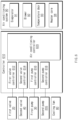
- FIG. 6 is a functional block diagram of a fuel cell system according to various embodiments.
- FIG. 7 illustrates a cooling degree according to an opening degree of a second valve.
- FIG. 8 illustrates a structure (e.g., a side section view) of the air conditioning system according to various embodiments.
- the configuration illustrated in FIG. 6 may be a hardware device or a program (or an application) including instructions.
- a controller 610 may be a hardware device, such as a processor or a central processing unit (CPU), or a program implemented by a processor.
- the controller 610 may be connected to the configurations of the fuel cell system to perform an overall function of the fuel cell system.
- the controller 610 may detect a failure of the cooling fan 80.
- the controller 610 may detect a disabled state of controller area network (CAN) communication between the controller 610 and the cooling fan 80, may detect that a temperature of the first cooling water does not change for a specific period of time, or may detect that power consumption of the cooling fan 80 does not change for a specific period of time.
- CAN controller area network
- the temperature of the first cooling water may be a temperature of the first cooling water at an inlet of the fuel cell stack 10, which is measured by a first temperature sensor 112. Because air cooling in the first radiator 60 (or the second radiator 70) through compulsory convection is not made when an operation of the cooling fan 80 is disabled, the temperature of the first cooling water heated in the fuel cell stack 10 may not be decreased by a specific temperature.
- the controller 610 may control the configurations of the fuel cell system to minimize overheating of the fuel cell system in a disabled state of the cooling fan 80. To achieve this, the controller 610 may include a first valve controller 612, a second valve controller 614, a first pump controller 616, a second pump controller 618, and an air conditioning controller 620.
- the configurations included in the controller may be implemented by individual devices (or programs) or may be implemented by one integrated module.
- the first valve controller 612 and the second valve controller 614 may control opening degrees of the first valve 20 and the second valve 40, respectively.
- the first valve controller 612 may control the first valve 20 such that the first cooling water does not flow to the first connection line 130 but flows to the fuel cell stack 10 and a heater core 94 of the air conditioning system 90 to secure a cooling degree of the fuel cell system.
- the second valve controller 614 may control the second valve 40 such that the first cooling water, which has passed through the fuel cell stack 10, does not flow to the third connection line 140 but flows to the first radiator 60 and the heater core 94 of the air conditioning system 90.
- the first cooling water may be cooled through natural convection while passing through the first radiator 60, and may be cooled through a blower 92 while passing through the heater core 94.
- the second valve controller 614 may control the opening degree of the second valve 40 to a specific value in consideration of the cooling degree of the air conditioning system 90 and the cooling degree of the first radiator 80.
- a transverse axis of the graph represents an opening angle (or may be referred to as 'an operation angle') (unit: degrees) of the second valve 40, and a longitudinal axis thereof may represent a flow rate (LPM) and a cooling degree (kW).
- a cooling degree (a radiator cooling degree) due to the radiator may increase while a flow rate of the first cooling water, on a side that is close to the radiator (e.g., the first radiator 60), increases, and a cooing degree (an air conditioning system cooling degree) due to the air conditioning system may decrease as a flow rate of the first cooling water, on a side that is close to the air conditioning system (e.g., the air conditioning system 90), decreases, as the opening angle increases.
- the second valve controller 614 may control the second valve 40 in consideration of an opening angle (e.g., K), at which a total sum of the radiator cooling degree and the air conditioning system cooling degree is maximal.
- a first pump controller 612 and a second pump controller 616 may control operations of the first pump 30 and the second pump 205, respectively. For example, when a failure of the cooling fan 80 is detected, a first pump controller 614 may control an RPM of the first pump 30 to a maximum level to secure the flow rate of the first cooling water at a maximum level. When the first cooling water may exchange heat with the second cooling water through the heat exchanger 300, the second pump controller 616 may control an RPM of the second pump 205 to a maximum level to increase a degree of heat exchange.
- An air conditioning system controller 620 may control at least one of the configurations 91 to 94 included in the air conditioning system 90 to maximize an amount of heat emitted in the heater core 94 when a failure of the cooling fan 80 is detected.
- the air conditioning system 90 may include a heater core 94 that performs a heating function, an evaporator 91 that cooling the air when the air conditioner is switched on, the blower 92 that guides the cooled air such that the air flows toward the heater core 94, and temperature doors 93-1 and 93-2 that interrupt flows of the air that flows to the heater core 94 through opening and closing thereof.
- the air conditioning system controller 620 may set an RPM of the blower 92 to a maximum level such that cold air generated through the evaporator 91 flows in a specific direction 805 and passes through the heater core 94, and may cause the air that has passed through the evaporator 91 to flow to the heater core 94 by controlling opening and closing of the temperature doors 93-1 and 93-2. For example, in the opened state, the first temperature door 93-1 may be moved downwards, and the second temperature door 93-2 may be moved upwards.
- FIG. 9 illustrates a flowchart of operations when a failure of a cooling fan is detected, according to various embodiments.
- the operations of the flowchart described hereafter may be implemented by the fuel cell system or may be implemented by the configurations (e.g., the controller 610) included in the fuel cell system.
- the fuel cell system may detect a failure of the cooling fan 80.
- the fuel cell system may open the first valve 20 such that the first cooling water flows toward the fuel cell stack 10.
- the fuel cell stack may control (set) the RPM of the blower 92 of the air conditioning system 90 to a maximum valve. Additionally, in operation 930, the fuel cell system may open the temperature doors 93-1 and 93-2 such that the cooled air passes through the heater core 94. Additionally, in operation 934, the fuel cell system may switch on and off the air conditioner based on whether a condenser is include therein. For example, when a condenser is not included in a vehicle cooling module including the first radiator 60, the second radiator 70, and the cooling fan 80, the fuel cell system may control the air conditioner to be switched on to cool the air.
- the fuel cell system may control the air conditioner to be switched on and off because the temperature of the first radiator 60 may be increased due to a rise in a temperature of the condenser when the air conditioner is operated.
- the fuel cell system may control the opening degree of the second valve 40 in consideration of the cooling degrees of the first radiator 60 and the air conditioning system 90.
- the fuel cell system may control the opening degree of the second valve 40 such that a total sum of the cooling degree of the first radiator 60 and the cooling degree of the air conditioning system 90 becomes maximal.
- the fuel cell stack may control the RPM of the first pump 30 to a maximum valve.
- the fuel cell system may control the RPM of the second pump 205 to a maximum level.
- FIG. 10 illustrates a flowchart of an operation of outputting a warning alarm according to various embodiments.
- the operations illustrated in FIG. 10 may be performed at an arbitrary time point after operation 910 of FIG. 9 .
- the fuel cell system may perform the operations illustrated in FIG. 10 , after operation 950 or after operation 910, 920, 930, 932, 934, or 940.
- the fuel cell system may monitor a temperature of the first cooling water at the inlet of the fuel cell stack 10.
- the controller 610 may monitor the temperature of the cooling water through the first temperature sensor 112.
- the fuel cell system may identify whether the monitored temperature of the cooling water exceeds a threshold value. Unless the temperature of the cooling water exceeds the threshold temperature, the fuel cell system may repeatedly perform operations 1010 to 1020.
- the fuel cell system may output a warning alarm to secure safety of the vehicle and the driver.
- the fuel cell system may protect damage to the fuel cell stack that is a device of a high price due to overheating even when a failure of a component for heat management, such as a cooling fan, is detected.
- the fuel cell system may secure an output of a system while a passenger and a vehicle move to a safe site even in an emergency situation, in which a component for heat management, such as a cooling fan, is detected.
- a component for heat management such as a cooling fan
- present disclosure may provide various effects that are directly or indirectly recognized.
Landscapes
- Engineering & Computer Science (AREA)
- Chemical & Material Sciences (AREA)
- Chemical Kinetics & Catalysis (AREA)
- Sustainable Development (AREA)
- Sustainable Energy (AREA)
- Manufacturing & Machinery (AREA)
- Life Sciences & Earth Sciences (AREA)
- Electrochemistry (AREA)
- General Chemical & Material Sciences (AREA)
- Physics & Mathematics (AREA)
- Thermal Sciences (AREA)
- Mechanical Engineering (AREA)
- Combustion & Propulsion (AREA)
- Fuel Cell (AREA)
Claims (15)
- Système de piles à combustible comprenant :un empilement de piles à combustible (10) ;une première conduite de refroidissement (110) comportant une première eau de refroidissement qui passe par l'empilement de piles à combustible (10) et y circule ;un premier radiateur (60) disposé sur la première conduite de refroidissement (110) et configuré pour refroidir la première eau de refroidissement ;un système de climatisation (90) disposé sur une première conduite de raccordement (130) qui forme une boucle de chauffage avec la première conduite de refroidissement (110) ;un premier ventilateur de refroidissement (80) configuré pour souffler de l'air extérieur vers le premier radiateur (60) ;une première vanne (20) configurée pour commuter un chemin d'écoulement de la première eau de refroidissement vers l'empilement de piles à combustible (10) ou vers un dispositif de chauffage (50) ;une seconde vanne (40) configurée pour commuter le chemin d'écoulement de la première eau de refroidissement vers l'empilement de piles à combustible (10) ou vers le premier radiateur (60) ;une première pompe (30) disposée sur la première conduite de refroidissement (110) et configurée pour pomper la première eau de refroidissement ; etun régulateur (610) raccordé au premier ventilateur de refroidissement (80), à la première vanne (20), à la seconde vanne (40) et à la première pompe (30),dans lequel le régulateur (610) est configuré :pour détecter une défaillance du premier ventilateur de refroidissement (80) ; etlorsqu'une défaillance du premier ventilateur de refroidissement (80) est détectée,pour ouvrir la première vanne (20) de telle sorte que la première eau de refroidissement s'écoule vers l'empilement de piles à combustible (10) ;pour réguler un régime d'une soufflante du système de climatisation (90) à un niveau maximal ;pour réguler un degré d'ouverture de la seconde vanne (40) selon un degré de refroidissement du premier radiateur (60) et un degré de refroidissement du système de climatisation (90) ; etpour réguler un régime de la première pompe (30) à un niveau maximal.
- Système de piles à combustible selon la revendication 1, dans lequel le régulateur (610) détecte la défaillance du premier ventilateur de refroidissement (80) en détectant un état désactivé d'une communication de réseau de zone de contrôleur (CAN), en détectant qu'une température de la première eau de refroidissement ne change pas pendant une période de temps spécifique, ou en détectant qu'une consommation de puissance du premier ventilateur de refroidissement (80) ne change pas pendant une période de temps spécifique.
- Système de piles à combustible selon la revendication 1, dans lequel le régulateur (610) est en outre configuré pour :
réguler une porte de température (93-1, 93-2) vers un état ouvert de telle sorte que l'air refroidi dans le système de climatisation (90) s'écoule vers un faisceau de chaufferette (94). - Système de piles à combustible selon la revendication 3, dans lequel le régulateur (610) est configuré pour :
allumer un climatiseur configuré pour refroidir l'air qui s'écoule vers le faisceau de chaufferette (94). - Système de piles à combustible selon la revendication 3, comprenant en outre :un condenseur,dans lequel le régulateur (610) est configuré pour :
éteindre un climatiseur configuré pour refroidir l'air qui s'écoule vers le faisceau de chaufferette (94). - Système de piles à combustible selon la revendication 1, comprenant en outre :une seconde conduite de refroidissement (120) comportant une seconde eau de refroidissement qui passe par une partie électronique de puissance et y circule ;un second radiateur (70) disposé sur la seconde conduite de refroidissement (120) et configuré pour refroidir la seconde eau de refroidissement ; etune seconde pompe (205) disposée sur la seconde conduite de refroidissement (120) et configurée pour pomper la seconde eau de refroidissement,dans lequel le régulateur (610) est configuré pour :
réguler un régime de la seconde pompe (205) à un niveau maximal. - Système de piles à combustible selon la revendication 6, dans lequel le premier ventilateur de refroidissement (80) est disposé pour souffler l'air extérieur autour du premier radiateur (60) et du second radiateur (70).
- Système de piles à combustible selon la revendication 6, comprenant en outre :
un second ventilateur de refroidissement (85) configuré pour souffler l'air extérieur autour du second radiateur (70). - Système de piles à combustible selon la revendication 6, comprenant en outre :
un échangeur de chaleur (300) disposé sur la première conduite de refroidissement (110) et la seconde conduite de refroidissement (120), et configuré pour échanger de la chaleur entre la première eau de refroidissement et la seconde eau de refroidissement. - Système de piles à combustible selon la revendication 1, dans lequel le régulateur (610) est configuré pour :surveiller une température de la première eau de refroidissement à une entrée de l'empilement de piles à combustible (10) ; etémettre une alarme d'avertissement lorsque la température de la première eau de refroidissement dépasse une température seuil.
- Procédé d'exploitation d'un système de piles à combustible selon l'une des revendications 1 à 10, le procédé comprenant :la détection d'une défaillance d'un premier ventilateur de refroidissement (80) configuré pour souffler de l'air extérieur vers un premier radiateur (60) ; etlorsqu'une défaillance du premier ventilateur de refroidissement (80) est détectée :l'ouverture d'une première vanne (20) de telle sorte qu'une première eau de refroidissement qui passe par l'empilement de piles à combustible (10) s'écoule vers l'empilement de piles à combustible (10) ;la régulation d'un régime d'une soufflante d'un système de climatisation (90) à un niveau maximal ;la régulation d'un degré d'ouverture d'une seconde vanne (40) selon un degré de refroidissement du premier radiateur (60) et un degré de refroidissement du système de climatisation (90) ; etla régulation d'un régime d'une première pompe (30) configurée pour pomper la première eau de refroidissement, à un niveau maximal.
- Procédé selon la revendication 11, dans lequel la détection de la défaillance du premier ventilateur de refroidissement inclut :la détection d'un état désactivé d'une communication CAN ;la détection du fait qu'une température de la première eau de refroidissement ne change pas pendant une période de temps spécifique ; oula détection du fait qu'une consommation de puissance de la première eau de refroidissement ne change pas pendant une période de temps spécifique.
- Procédé selon la revendication 11, comprenant en outre :
la régulation d'une porte de température (93-1, 93-2) vers un état ouvert de telle sorte que l'air refroidi dans le système de climatisation (90) s'écoule vers un faisceau de chaufferette (94). - Procédé selon la revendication 13, comprenant en outre :
la régulation d'un climatiseur configuré pour refroidir l'air refroidi qui s'écoule vers le faisceau de chaufferette (94) vers un état allumé ou éteint, selon qu'un condenseur est inclus ou non dans le système de piles à combustible. - Procédé selon la revendication 11, comprenant en outre :
la régulation d'un régime d'une seconde pompe (205) configurée pour pomper la seconde eau de refroidissement qui passe par une partie électronique de puissance, à un niveau maximal.
Applications Claiming Priority (1)
| Application Number | Priority Date | Filing Date | Title |
|---|---|---|---|
| KR1020210089371A KR102600177B1 (ko) | 2021-07-07 | 2021-07-07 | 연료전지 시스템에서 결함에 대처하기 위한 방법 |
Publications (2)
| Publication Number | Publication Date |
|---|---|
| EP4117063A1 EP4117063A1 (fr) | 2023-01-11 |
| EP4117063B1 true EP4117063B1 (fr) | 2024-03-27 |
Family
ID=78819286
Family Applications (1)
| Application Number | Title | Priority Date | Filing Date |
|---|---|---|---|
| EP21210917.7A Active EP4117063B1 (fr) | 2021-07-07 | 2021-11-29 | Procédé de traitement des défaillances dans un système de piles à combustible |
Country Status (5)
| Country | Link |
|---|---|
| US (1) | US11791484B2 (fr) |
| EP (1) | EP4117063B1 (fr) |
| JP (1) | JP2023010526A (fr) |
| KR (1) | KR102600177B1 (fr) |
| CN (1) | CN115602889A (fr) |
Families Citing this family (3)
| Publication number | Priority date | Publication date | Assignee | Title |
|---|---|---|---|---|
| CN111141948B (zh) * | 2019-12-30 | 2020-09-22 | 深圳市芯天下技术有限公司 | 一种掉电检测电路 |
| JP2022157510A (ja) * | 2021-03-31 | 2022-10-14 | 本田技研工業株式会社 | 燃料電池システムの運転方法 |
| KR102575043B1 (ko) | 2023-02-07 | 2023-09-07 | 주식회사 시너지 | 고효율 연료전지 시스템 및 그 제어 방법 |
Family Cites Families (4)
| Publication number | Priority date | Publication date | Assignee | Title |
|---|---|---|---|---|
| KR101610076B1 (ko) * | 2010-12-06 | 2016-04-07 | 현대자동차주식회사 | 연료 전지 냉각 시스템 |
| KR101284343B1 (ko) | 2011-12-08 | 2013-07-08 | 현대자동차주식회사 | 연료전지 차량의 냉각팬 관리장치 및 방법 |
| KR102518235B1 (ko) * | 2017-12-07 | 2023-04-06 | 현대자동차주식회사 | 연료전지 열관리 시스템 및 그 제어방법 |
| CN110993987B (zh) * | 2019-12-20 | 2021-01-12 | 东风汽车集团有限公司 | 燃料电池汽车冷却系统及其控制方法 |
-
2021
- 2021-07-07 KR KR1020210089371A patent/KR102600177B1/ko active IP Right Grant
- 2021-11-29 US US17/536,692 patent/US11791484B2/en active Active
- 2021-11-29 EP EP21210917.7A patent/EP4117063B1/fr active Active
- 2021-12-16 JP JP2021204495A patent/JP2023010526A/ja active Pending
- 2021-12-20 CN CN202111567185.0A patent/CN115602889A/zh active Pending
Also Published As
| Publication number | Publication date |
|---|---|
| KR20230008558A (ko) | 2023-01-16 |
| JP2023010526A (ja) | 2023-01-20 |
| EP4117063A1 (fr) | 2023-01-11 |
| US20230008445A1 (en) | 2023-01-12 |
| US11791484B2 (en) | 2023-10-17 |
| CN115602889A (zh) | 2023-01-13 |
| KR102600177B1 (ko) | 2023-11-09 |
Similar Documents
| Publication | Publication Date | Title |
|---|---|---|
| EP4117063B1 (fr) | Procédé de traitement des défaillances dans un système de piles à combustible | |
| EP4113674B1 (fr) | Procédé pour traiter des défaillances dans un système de pile à combustible | |
| US11450873B2 (en) | Fuel cell system for thermal management and method thereof | |
| EP4092791B1 (fr) | Procédé et appareil pour régler la température d'un réfrigérant dans un système de pile à combustible | |
| KR102595285B1 (ko) | 연료전지 시스템에서 효율 개선을 위한 방법 | |
| KR20230020621A (ko) | 연료전지 차량의 열 관리 시스템 | |
| US20240063412A1 (en) | Fuel cell system and thermal management method thereof | |
| US11791487B2 (en) | Method for optimizing performance in fuel cell system | |
| US20230077249A1 (en) | Fuel cell system and method of controlling heater thereof | |
| KR102659321B1 (ko) | 연료전지 시스템에서 냉각수 온도를 제어하기 위한 방법 | |
| US20240105978A1 (en) | Fuel cell system and method of controlling same | |
| KR20220148656A (ko) | 연료전지 시스템에서 펌프를 제어하기 위한 방법 | |
| KR20230021207A (ko) | 연료전지 시스템 및 그의 비상 운전 제어 방법 |
Legal Events
| Date | Code | Title | Description |
|---|---|---|---|
| PUAI | Public reference made under article 153(3) epc to a published international application that has entered the european phase |
Free format text: ORIGINAL CODE: 0009012 |
|
| STAA | Information on the status of an ep patent application or granted ep patent |
Free format text: STATUS: REQUEST FOR EXAMINATION WAS MADE |
|
| 17P | Request for examination filed |
Effective date: 20211129 |
|
| AK | Designated contracting states |
Kind code of ref document: A1 Designated state(s): AL AT BE BG CH CY CZ DE DK EE ES FI FR GB GR HR HU IE IS IT LI LT LU LV MC MK MT NL NO PL PT RO RS SE SI SK SM TR |
|
| RBV | Designated contracting states (corrected) |
Designated state(s): AL AT BE BG CH CY CZ DE DK EE ES FI FR GB GR HR HU IE IS IT LI LT LU LV MC MK MT NL NO PL PT RO RS SE SI SK SM TR |
|
| GRAP | Despatch of communication of intention to grant a patent |
Free format text: ORIGINAL CODE: EPIDOSNIGR1 |
|
| STAA | Information on the status of an ep patent application or granted ep patent |
Free format text: STATUS: GRANT OF PATENT IS INTENDED |
|
| RIC1 | Information provided on ipc code assigned before grant |
Ipc: H01M 8/04746 20160101ALI20230921BHEP Ipc: H01M 8/04664 20160101ALI20230921BHEP Ipc: H01M 8/04029 20160101AFI20230921BHEP |
|
| INTG | Intention to grant announced |
Effective date: 20231020 |
|
| RAP3 | Party data changed (applicant data changed or rights of an application transferred) |
Owner name: HYUNDAI MOBIS CO., LTD. |
|
| GRAS | Grant fee paid |
Free format text: ORIGINAL CODE: EPIDOSNIGR3 |
|
| GRAA | (expected) grant |
Free format text: ORIGINAL CODE: 0009210 |
|
| STAA | Information on the status of an ep patent application or granted ep patent |
Free format text: STATUS: THE PATENT HAS BEEN GRANTED |
|
| P01 | Opt-out of the competence of the unified patent court (upc) registered |
Effective date: 20240208 |
|
| AK | Designated contracting states |
Kind code of ref document: B1 Designated state(s): AL AT BE BG CH CY CZ DE DK EE ES FI FR GB GR HR HU IE IS IT LI LT LU LV MC MK MT NL NO PL PT RO RS SE SI SK SM TR |
|
| REG | Reference to a national code |
Ref country code: GB Ref legal event code: FG4D |
|
| REG | Reference to a national code |
Ref country code: CH Ref legal event code: EP |
|
| REG | Reference to a national code |
Ref country code: DE Ref legal event code: R096 Ref document number: 602021010912 Country of ref document: DE |