EP4116004A1 - Information providing device and determination system - Google Patents
Information providing device and determination system Download PDFInfo
- Publication number
- EP4116004A1 EP4116004A1 EP21763628.1A EP21763628A EP4116004A1 EP 4116004 A1 EP4116004 A1 EP 4116004A1 EP 21763628 A EP21763628 A EP 21763628A EP 4116004 A1 EP4116004 A1 EP 4116004A1
- Authority
- EP
- European Patent Office
- Prior art keywords
- information
- metal pipe
- forming
- formed product
- providing device
- Prior art date
- Legal status (The legal status is an assumption and is not a legal conclusion. Google has not performed a legal analysis and makes no representation as to the accuracy of the status listed.)
- Pending
Links
Images



Classifications
-
- B—PERFORMING OPERATIONS; TRANSPORTING
- B21—MECHANICAL METAL-WORKING WITHOUT ESSENTIALLY REMOVING MATERIAL; PUNCHING METAL
- B21D—WORKING OR PROCESSING OF SHEET METAL OR METAL TUBES, RODS OR PROFILES WITHOUT ESSENTIALLY REMOVING MATERIAL; PUNCHING METAL
- B21D24/00—Special deep-drawing arrangements in, or in connection with, presses
- B21D24/10—Devices controlling or operating blank holders independently, or in conjunction with dies
-
- B—PERFORMING OPERATIONS; TRANSPORTING
- B21—MECHANICAL METAL-WORKING WITHOUT ESSENTIALLY REMOVING MATERIAL; PUNCHING METAL
- B21D—WORKING OR PROCESSING OF SHEET METAL OR METAL TUBES, RODS OR PROFILES WITHOUT ESSENTIALLY REMOVING MATERIAL; PUNCHING METAL
- B21D26/00—Shaping without cutting otherwise than using rigid devices or tools or yieldable or resilient pads, i.e. applying fluid pressure or magnetic forces
- B21D26/02—Shaping without cutting otherwise than using rigid devices or tools or yieldable or resilient pads, i.e. applying fluid pressure or magnetic forces by applying fluid pressure
- B21D26/033—Deforming tubular bodies
-
- B—PERFORMING OPERATIONS; TRANSPORTING
- B21—MECHANICAL METAL-WORKING WITHOUT ESSENTIALLY REMOVING MATERIAL; PUNCHING METAL
- B21C—MANUFACTURE OF METAL SHEETS, WIRE, RODS, TUBES, PROFILES OR LIKE SEMI-MANUFACTURED PRODUCTS OTHERWISE THAN BY ROLLING; AUXILIARY OPERATIONS USED IN CONNECTION WITH METAL-WORKING WITHOUT ESSENTIALLY REMOVING MATERIAL
- B21C51/00—Measuring, gauging, indicating, counting, or marking devices specially adapted for use in the production or manipulation of material in accordance with subclasses B21B - B21F
- B21C51/005—Marking devices
-
- B—PERFORMING OPERATIONS; TRANSPORTING
- B21—MECHANICAL METAL-WORKING WITHOUT ESSENTIALLY REMOVING MATERIAL; PUNCHING METAL
- B21D—WORKING OR PROCESSING OF SHEET METAL OR METAL TUBES, RODS OR PROFILES WITHOUT ESSENTIALLY REMOVING MATERIAL; PUNCHING METAL
- B21D22/00—Shaping without cutting, by stamping, spinning, or deep-drawing
- B21D22/20—Deep-drawing
- B21D22/30—Deep-drawing to finish articles formed by deep-drawing
-
- B—PERFORMING OPERATIONS; TRANSPORTING
- B21—MECHANICAL METAL-WORKING WITHOUT ESSENTIALLY REMOVING MATERIAL; PUNCHING METAL
- B21D—WORKING OR PROCESSING OF SHEET METAL OR METAL TUBES, RODS OR PROFILES WITHOUT ESSENTIALLY REMOVING MATERIAL; PUNCHING METAL
- B21D26/00—Shaping without cutting otherwise than using rigid devices or tools or yieldable or resilient pads, i.e. applying fluid pressure or magnetic forces
- B21D26/02—Shaping without cutting otherwise than using rigid devices or tools or yieldable or resilient pads, i.e. applying fluid pressure or magnetic forces by applying fluid pressure
- B21D26/033—Deforming tubular bodies
- B21D26/047—Mould construction
-
- B—PERFORMING OPERATIONS; TRANSPORTING
- B21—MECHANICAL METAL-WORKING WITHOUT ESSENTIALLY REMOVING MATERIAL; PUNCHING METAL
- B21D—WORKING OR PROCESSING OF SHEET METAL OR METAL TUBES, RODS OR PROFILES WITHOUT ESSENTIALLY REMOVING MATERIAL; PUNCHING METAL
- B21D37/00—Tools as parts of machines covered by this subclass
- B21D37/16—Heating or cooling
-
- B—PERFORMING OPERATIONS; TRANSPORTING
- B23—MACHINE TOOLS; METAL-WORKING NOT OTHERWISE PROVIDED FOR
- B23K—SOLDERING OR UNSOLDERING; WELDING; CLADDING OR PLATING BY SOLDERING OR WELDING; CUTTING BY APPLYING HEAT LOCALLY, e.g. FLAME CUTTING; WORKING BY LASER BEAM
- B23K26/00—Working by laser beam, e.g. welding, cutting or boring
- B23K26/352—Working by laser beam, e.g. welding, cutting or boring for surface treatment
-
- B—PERFORMING OPERATIONS; TRANSPORTING
- B23—MACHINE TOOLS; METAL-WORKING NOT OTHERWISE PROVIDED FOR
- B23K—SOLDERING OR UNSOLDERING; WELDING; CLADDING OR PLATING BY SOLDERING OR WELDING; CUTTING BY APPLYING HEAT LOCALLY, e.g. FLAME CUTTING; WORKING BY LASER BEAM
- B23K26/00—Working by laser beam, e.g. welding, cutting or boring
- B23K26/352—Working by laser beam, e.g. welding, cutting or boring for surface treatment
- B23K26/359—Working by laser beam, e.g. welding, cutting or boring for surface treatment by providing a line or line pattern, e.g. a dotted break initiation line
-
- B—PERFORMING OPERATIONS; TRANSPORTING
- B23—MACHINE TOOLS; METAL-WORKING NOT OTHERWISE PROVIDED FOR
- B23K—SOLDERING OR UNSOLDERING; WELDING; CLADDING OR PLATING BY SOLDERING OR WELDING; CUTTING BY APPLYING HEAT LOCALLY, e.g. FLAME CUTTING; WORKING BY LASER BEAM
- B23K26/00—Working by laser beam, e.g. welding, cutting or boring
- B23K26/36—Removing material
- B23K26/38—Removing material by boring or cutting
-
- G—PHYSICS
- G05—CONTROLLING; REGULATING
- G05B—CONTROL OR REGULATING SYSTEMS IN GENERAL; FUNCTIONAL ELEMENTS OF SUCH SYSTEMS; MONITORING OR TESTING ARRANGEMENTS FOR SUCH SYSTEMS OR ELEMENTS
- G05B19/00—Program-control systems
- G05B19/02—Program-control systems electric
- G05B19/418—Total factory control, i.e. centrally controlling a plurality of machines, e.g. direct or distributed numerical control [DNC], flexible manufacturing systems [FMS], integrated manufacturing systems [IMS] or computer integrated manufacturing [CIM]
-
- G—PHYSICS
- G05—CONTROLLING; REGULATING
- G05B—CONTROL OR REGULATING SYSTEMS IN GENERAL; FUNCTIONAL ELEMENTS OF SUCH SYSTEMS; MONITORING OR TESTING ARRANGEMENTS FOR SUCH SYSTEMS OR ELEMENTS
- G05B19/00—Program-control systems
- G05B19/02—Program-control systems electric
- G05B19/418—Total factory control, i.e. centrally controlling a plurality of machines, e.g. direct or distributed numerical control [DNC], flexible manufacturing systems [FMS], integrated manufacturing systems [IMS] or computer integrated manufacturing [CIM]
- G05B19/4183—Total factory control, i.e. centrally controlling a plurality of machines, e.g. direct or distributed numerical control [DNC], flexible manufacturing systems [FMS], integrated manufacturing systems [IMS] or computer integrated manufacturing [CIM] characterised by data acquisition, e.g. workpiece identification
-
- G—PHYSICS
- G06—COMPUTING OR CALCULATING; COUNTING
- G06K—GRAPHICAL DATA READING; PRESENTATION OF DATA; RECORD CARRIERS; HANDLING RECORD CARRIERS
- G06K1/00—Methods or arrangements for marking the record carrier in digital fashion
- G06K1/12—Methods or arrangements for marking the record carrier in digital fashion otherwise than by punching
-
- G—PHYSICS
- G06—COMPUTING OR CALCULATING; COUNTING
- G06Q—INFORMATION AND COMMUNICATION TECHNOLOGY [ICT] SPECIALLY ADAPTED FOR ADMINISTRATIVE, COMMERCIAL, FINANCIAL, MANAGERIAL OR SUPERVISORY PURPOSES; SYSTEMS OR METHODS SPECIALLY ADAPTED FOR ADMINISTRATIVE, COMMERCIAL, FINANCIAL, MANAGERIAL OR SUPERVISORY PURPOSES, NOT OTHERWISE PROVIDED FOR
- G06Q50/00—Information and communication technology [ICT] specially adapted for implementation of business processes of specific business sectors, e.g. utilities or tourism
- G06Q50/04—Manufacturing
-
- B—PERFORMING OPERATIONS; TRANSPORTING
- B21—MECHANICAL METAL-WORKING WITHOUT ESSENTIALLY REMOVING MATERIAL; PUNCHING METAL
- B21D—WORKING OR PROCESSING OF SHEET METAL OR METAL TUBES, RODS OR PROFILES WITHOUT ESSENTIALLY REMOVING MATERIAL; PUNCHING METAL
- B21D26/00—Shaping without cutting otherwise than using rigid devices or tools or yieldable or resilient pads, i.e. applying fluid pressure or magnetic forces
- B21D26/02—Shaping without cutting otherwise than using rigid devices or tools or yieldable or resilient pads, i.e. applying fluid pressure or magnetic forces by applying fluid pressure
- B21D26/033—Deforming tubular bodies
- B21D26/041—Means for controlling fluid parameters, e.g. pressure or temperature
-
- G—PHYSICS
- G05—CONTROLLING; REGULATING
- G05B—CONTROL OR REGULATING SYSTEMS IN GENERAL; FUNCTIONAL ELEMENTS OF SUCH SYSTEMS; MONITORING OR TESTING ARRANGEMENTS FOR SUCH SYSTEMS OR ELEMENTS
- G05B2219/00—Program-control systems
- G05B2219/30—Nc systems
- G05B2219/45—Nc applications
- G05B2219/45134—Marking
Definitions
- One aspect of the present invention relates to an information providing device and a determination system.
- Patent Document 1 discloses a forming device including a forming die having a lower die and an upper die paired with each other, a gas supply portion that supplies gas into a metal pipe material held between the forming dies, and a heating unit that heats the metal pipe material by energization and heating.
- information may be provided to a die-formed product by marking in order to secure traceability.
- a method of giving the information to the formed product there are a method of performing marking in advance before the forming and a method of performing marking simultaneously with the forming with the forming device.
- the marking methods there is a possibility that a mark disappears or becomes unclear along with the forming, and there is a case where the traceability is not secured.
- the information only simple information such as a lot of the formed product was included.
- the information marked on the formed product includes only information such as the lot, there are problems in that it is not possible to specify under what conditions the formed product has been formed and sufficient traceability cannot be secured.
- One aspect of the present invention has been made to solve such a problem, and an object of the present invention is to provide an information providing device and a determination system capable of improving the traceability of a formed product.
- the information providing device is an information providing device that provides information to a formed product formed by a forming device having a die.
- the information is provided to the formed product after being formed by the forming device, and the information is information from which at least forming conditions of the formed product are acquirable.
- the information providing device provides the information to the formed product after being formed by the forming device. Therefore, it is possible to avoid a situation in which the information provided to the formed product disappears along with the forming. Additionally, the information is information from which at least the forming conditions of the formed product are acquirable. Therefore, for example, in a case where there is a problem with the formed product in a subsequent inspection process, it is possible to specify under what forming conditions the formed product is formed. From the above, the traceability of the formed product can be improved.
- the information may be represented in such a manner that the forming conditions are directly readable.
- the forming conditions can be quickly read from the information reflected in the formed product without referring to the forming conditions in the database.
- the information may be represented in such a manner that the database associated with the forming conditions is capable of being referred to. In this case, even if the information reflected in the formed product is simple, many forming conditions can be acquired by referring to the database.
- the information providing device is an information providing device that provides information to a formed product formed by a forming device having a die, and the information providing device provides the information to each formed product whenever one formed product is formed by the forming device.
- the information providing device provides the information to each formed product whenever one formed product is formed by the forming device. Therefore, the information providing device can directly provide the information to an individual formed product. Therefore, for example, in a case where there is a problem with the formed product in a subsequent inspection process, the information can be directly acquired from the formed product. From the above, the traceability of the formed product can be improved.
- the information providing device may be provided between the forming device and an accumulation unit that accumulates a plurality of the formed products .
- an accumulation unit that accumulates a plurality of the formed products .
- the determination system is a determination system that determines a formed product formed by a forming device having a die. Forming conditions of the formed product are determined on the basis of information provided to the formed product, and the information is information from which at least the forming conditions of the formed product are acquirable.
- the information is information from which at least the forming conditions of the formed product are acquirable. Therefore, for example, in a case where there is a problem with the formed product in a subsequent inspection process, it is possible to specify under what forming conditions the formed product is formed. Therefore, the determination system can specify the forming conditions of a formed product having a problem by determining the forming conditions of the formed product on the basis of the information provided to the formed product. From the above, the traceability of the formed product can be improved.
- the information providing device and the determination system that can improve the traceability of the formed product.
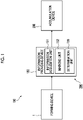
- Fig. 1 is a block diagram of a formed product manufacturing system 100 including an information providing device 150 according to the present embodiment.
- the formed product manufacturing system 100 includes a forming device 1, an information providing device 150, and an accumulation device 200 (accumulation unit).
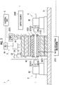
- Fig. 2 is a schematic diagram of the forming device 1 according to the present embodiment.
- the forming device 1 is a device that forms a metal pipe (formed product) having a hollow shape by blow forming.
- the forming device 1 is installed on a horizontal plane.
- the forming device 1 includes a forming die 2, a drive mechanism 3, a holding unit 4, a heating unit 5, a fluid supply unit 6, a cooling unit 7, and a control unit 8.
- the metal pipe refers to a hollow article after the forming in the forming device 1 is completed
- a metal pipe material 40 (metal material) refers to a hollow article before the forming in the forming device 1 is completed.
- the metal pipe material 40 is a steel type pipe material that can be hardened. Additionally, in the horizontal direction, a direction in which the metal pipe material 40 extends during forming may be referred to as a "longitudinal direction", and a direction perpendicular to the longitudinal direction may be referred to as a "width direction”.
- the forming die 2 is a die that forms the metal pipe material 40 into a metal pipe, and includes a lower die 11 (first die) and an upper die 12 (second die) that face each other in the vertical direction.
- the lower die 11 and the upper die 12 are made of steel blocks.
- the lower die 11 is fixed to a base stage 13 via a die holder or the like.
- the upper die 12 is fixed to a slide of the drive mechanism 3 via a die holder or the like.
- the drive mechanism 3 is a mechanism that moves at least one of the lower die 11 and the upper die 12.
- the drive mechanism 3 has a configuration in which only the upper die 12 is moved.
- the drive mechanism 3 includes a slide 21 that moves the upper die 12 such that the lower die 11 and the upper die 12 are joined together, and a pull-back cylinder 22 serving as an actuator that generates a force for pulling the slide 21 upward, a main cylinder 23 serving as a drive source that downward-pressurizes the slide 21, and a drive source 24 that applies a driving force to the main cylinder 23.
- the holding unit 4 is a mechanism that holds the metal pipe material 40 disposed between the lower die 11 and the upper die 12.
- the holding unit 4 includes a lower electrode 26 and an upper electrode 27 that hold the metal pipe material 40 on one end side in the longitudinal direction of the forming die 2, and a lower electrode 26 and an upper electrode 27 that holds the metal pipe material 40 on the other end side in the longitudinal direction of the forming die 2.
- the lower electrodes 26 and the upper electrodes 27 on both sides in the longitudinal direction hold the metal pipe material 40 by sandwiching the vicinity of an end portion of the metal pipe material 40 from the vertical direction.
- groove portions having a shape corresponding to an outer peripheral surface of the metal pipe material 40 are formed on an upper surface of the lower electrode 26 and a lower surface of the upper electrode 27.
- the lower electrode 26 and the upper electrode 27 are provided with drive mechanisms (not shown) and are movable independently in the vertical direction.
- the heating unit 5 heats the metal pipe material 40.
- the heating unit 5 is a mechanism that heats the metal pipe material 40 by energizing the metal pipe material 40.
- the heating unit 5 heats the metal pipe material 40 in a state where the metal pipe material 40 is spaced apart from the lower die 11 and the upper die 12 between the lower die 11 and the upper die 12.
- the heating unit 5 includes the lower electrodes 26 and the upper electrodes 27 on both sides in the longitudinal direction described above, and a power supply 28 that allows an electric current to flow to the metal pipe material through the electrodes 26 and 27.
- the heating unit may be disposed in the previous process of the forming device 1 and performs heating externally.
- the fluid supply unit 6 is a mechanism that supplies a high-pressure fluid into the metal pipe material 40 held between the lower die 11 and the upper die 12.
- the fluid supply unit 6 supplies the high-pressure fluid to the metal pipe material 40 that has been brought into a high-temperature state by being heated by the heating unit 5, and expands the metal pipe material 40.
- the fluid supply unit 6 is provided on both end sides of the forming die 2 in the longitudinal direction.
- the fluid supply unit 6 includes a nozzle 31 that supplies fluid from an opening of an end portion of the metal pipe material 40 to the inside of the metal pipe material 40, and a drive mechanism 32 that moves the nozzle 31 forward and backward with respect to the opening of the metal pipe material 40, and a supply source 33 that supplies the high-pressure fluid into the metal pipe material 40 via the nozzle 31.
- the nozzle 31 is brought into close contact with the end portion of the metal pipe material 40 in a state where the sealing performance is secured during fluid supply and exhaust (refer to Fig. 3 ), and at other times, the nozzle 31 is spaced apart from the end portion of the metal pipe material 40.
- the fluid supply unit 6 may supply a gas such as high-pressure air or an inert gas as the fluid.
- the fluid supply unit 6 may be the same device including the heating unit 5 together with the holding unit 4 having a mechanism that moves the metal pipe material 40 in the vertical direction.
- Fig. 3 is a cross-sectional view showing an aspect when the nozzle 31 seals the metal pipe material 40.
- the nozzle 31 is a cylindrical member into which the end portion of the metal pipe material 40 is insertable.
- the nozzle 31 is supported by the drive mechanism 32 such that a center line of the nozzle 31 coincides with a reference line SL1.
- the inner diameter of a feed port 31a of an end portion of the nozzle 31 on the metal pipe material 40 side substantially coincides with the outer diameter of the metal pipe material 40 after expansion forming. In this state, the nozzle 31 supplies the high-pressure fluid from an internal flow path 63 to the metal pipe material 40.
- the cooling unit 7 is a mechanism that cools the forming die 2. By cooling the forming die 2, the cooling unit 7 can rapidly cool the metal pipe material 40 when the expanded metal pipe material 40 has come into contact with a forming surface of the forming die 2.
- the cooling unit 7 includes a flow path 36 formed inside the lower die 11 and the upper die 12, and a water circulation mechanism 37 that supplies and circulates cooling water to the flow path 36.
- the control unit 8 is a device that controls the entire forming device 1.
- the control unit 8 controls the drive mechanism 3, the holding unit 4, the heating unit 5, the fluid supply unit 6, and the cooling unit 7.
- the control unit 8 repeatedly performs an operation of forming the metal pipe material 40 with the forming die 2.
- control unit 8 controls, for example, the transport timing from a transport device such as a robot arm to dispose the metal pipe material 40 between the lower die 11 and the upper die 12 in an open state.
- the control unit 8 may wait for a worker to manually dispose the metal pipe material 40 between the lower die 11 and the upper die 12.
- the control unit 8 supports the metal pipe material 40 with the lower electrodes 26 on both sides in the longitudinal direction, and then controls the actuator of the holding unit 4 so as to lower the upper electrode 27 to sandwich the metal pipe material 40.
- the control unit 8 controls the heating unit 5 to energize and heat the metal pipe material 40. Accordingly, an axial electric current flows through the metal pipe material 40, and the electric resistance of the metal pipe material 40 itself causes the metal pipe material 40 itself to generate heat due to Joule heat.
- the control unit 8 controls the drive mechanism 3 to lower the upper die 12 and bring the upper die 12 closer to the lower die 11 to close the forming die 2.
- the control unit 8 controls the fluid supply unit 6 to seal the openings of both ends of the metal pipe material 40 with the nozzle 31 and supply the fluid. Accordingly, the metal pipe material 40 softened by heating expands and comes into contact with the forming surface of the forming die 2. Then, the metal pipe material 40 is formed so as to follow the shape of the forming surface of the forming die 2. When the metal pipe material 40 comes into contact with the forming surface, hardening of the metal pipe material 40 is performed by being quenched with the forming die 2 cooled by the cooling unit 7.
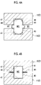
- the control unit 8 performs blow forming (primary blowing) by closing the forming die 2 and supplying the fluid to the metal pipe material 40 by the fluid supply unit 6.
- the control unit 8 forms a pipe portion 43 at a main cavity portion MC and causes a portion corresponding to a flange portion 44 to enter a sub-cavity portion SC.
- the control unit 8 forms the flange portion 44 by further closing the forming die 2 and further crushing the portion that has entered the sub-cavity portion SC.
- the control unit 8 performs blow forming at a higher pressure (secondary blowing).
- the control unit 8 performs die opening by raising the upper die 12 to space the upper die 21 apart from the metal pipe material 40. Accordingly, the metal pipe 41 is formed.
- the metal pipe 41 as shown in Figs. 5A and 5B is formed.
- the metal pipe 41 has the pipe portion 43 that extends in the longitudinal direction, and the flange portion 44 that overhangs from the pipe portion 43. Additionally, the metal pipe 41 has surplus parts 45 held by the holding unit 4 or sealed by the nozzle 31 at both ends in the longitudinal direction.
- the information providing device 150 is a device that provides information to the metal pipe 41 (refer to Figs. 5A and 5B ) formed by the forming device 1.
- the information providing device 150 provides information by marking the surface of any spot of the metal pipe 41.
- the information providing device 150 provides information to the metal pipe 41 after being formed by the forming device 1.
- the metal pipe 41 after being formed means the metal pipe 41 after the forming is completed and the metal pipe 41 exits from the forming device 1.
- the information providing device 150 provides the information to each metal pipe 41 whenever one metal pipe 41 is formed by the forming device 1.
- the information providing device 150 is provided between the forming device 1 and the accumulation device 200 for accumulating a plurality of formed products. Therefore, the metal pipe 41 after being marked by the information providing device 150 is accumulated by the accumulation device 200.
- the information providing device 150 includes an information acquisition unit 151, a marking unit 152, and a determination unit 155.
- the information acquisition unit 151 acquires information to be provided to the metal pipe 41.
- the information provided by the information providing device 150 is information from which at least the forming conditions of the metal pipe 41 are acquirable. Therefore, the information acquisition unit 151 acquires the forming conditions of the metal pipe 41 immediately after the forming from the control unit 8 of the forming device 1.
- the forming conditions include information such as the heating temperature of the metal pipe material 40, the die opening width for overhanging the flange portion 44 (refer to Fig. 5 ) of the metal pipe 41, the pressure and timing of the primary blowing, the die clamping force and timing for forming the pipe portion 43 (refer to Figs. 5A and 5B ), and the pressure and timing of the secondary blowing.
- the control unit 8 of the forming device 1 identifies the forming conditions as preset set values, or identifies the preset values as measured values when being actually formed. Therefore, the information acquisition unit 151 acquires the forming conditions from the control unit 8. In addition, in addition to the forming conditions, the information acquisition unit 151 also acquires information such as the material and the environment (temperature, humidity, or the like) during the forming, and the information providing device 150 may provide such information as well.
- the marking unit 152 provides information by marking the metal pipe 41.
- the marking unit 152 marks the information on the metal pipe 41 so as to reflect the information acquired by the information acquisition unit 151.
- the marking unit 152 may perform marking by using, for example, laser machining.
- the marking unit 152 may be configured by a laser device 153.
- the laser device 153 marks the surface of the metal pipe 41 by irradiating the surface with a laser beam.
- the laser device 153 may immediately cut the surplus part 45 after the marking has been formed (refer to Fig. 6B ). In this way, a laser cutting device can be diverted as the marking unit 152.
- a marking method of the marking unit 152 is not limited to the laser machining, and for example, the marking may be performed by a method such as printing, cutting work, or marking-off.
- the laser device 153 it is preferable to use the laser device 153 as the marking unit 152 from the viewpoint of easiness of machining and the fact that it is difficult to erase unlike a printed mark.
- the marking unit 152 marks an information display spot 170 on a flat surface portion of the pipe portion 43 to provide information.
- the information display spot 170 is set at a spot on one end side of the pipe portion 43 in the longitudinal direction.
- the information display spot 170 may be set at any spot of the metal pipe 41 as long as the information display spot 170 is readable (however, the surplus part 45 is excluded).
- the information provided to the metal pipe 41 is at least information from which the forming conditions of a formed product are acquirable. As shown in Fig. 5B , the information may be expressed by characters. However, the information may be expressed by a symbol or a combination of characters and symbols.
- the information may be represented in such a manner that the forming conditions are directly readable.
- the marking unit 152 may directly write characters and numbers showing the forming conditions on the metal pipe 41.
- the marking unit 152 may directly describe "heating temperature : XX°C., primary blowing pressure: YY MPa, secondary blowing pressure: ZZ MPa", or the like, on the metal pipe 41.
- the marking unit 152 may simply write the forming conditions on the metal pipe 41.
- the rule that "conditions of heating temperature, primary blowing pressure, secondary blowing pressure, or the like are shown in order from the left" is preset, and the marking unit 152 describes "XX-YY-ZZ" or the like to the metal pipe 41.
- the determination unit 155 can acquire the forming conditions that "the heating temperature is XX°C, the primary blowing pressure is YY MPa, and the secondary blowing pressure is ZZ MPa" during reading.
- the information may be represented in such a manner that a database associated with the forming conditions is capable of being referred to.
- the marking unit 152 writes identifiable contents such as characters, numbers, QR codes (registered trademarks), barcodes, or symbols on the metal pipe 41.
- the determination unit 155 reads the forming conditions, the written contents are compared with the database of the forming conditions, and the forming conditions are derived.
- the information providing device 150 provides a unique number to a certain metal pipe 41, and registers the number and the forming conditions unique to the metal pipe 41 in the database. Accordingly, the determination unit 155 can acquire the forming conditions corresponding to the number by reading the number marked on the metal pipe 41 and referring to the database.
- the determination unit 155 determines the forming conditions on the basis of the information provided to the metal pipe 41.
- the information providing device 150 since the information providing device 150 has the determination unit 155, the information providing device 150 constitutes the determination system 300.
- the determination system 300 is a system that performs determination on a formed product.
- the determination unit 155 determines the forming conditions of the metal pipe 41 on the basis of the information provided to the metal pipe 41. Specifically, the determination unit 155 determines the forming conditions by performing the processing as described above.
- the accumulation device 200 is a device that accumulates a plurality of the metal pipes 41. As shown in Fig. 6C , the accumulation device 200 may include a robot arm 201 that holds the metal pipe 41. After the marking by the information providing device 150 is completed, the robot arm 201 holds the metal pipe 41 and places the metal pipe 41 on an accumulation bogie 202. The robot arm 201 accumulates the metal pipe 41 by stacking the metal pipe 41 on the accumulation bogie 202 by repeating the operation.
- the information providing device 150 is an information providing device 150 that provides information to the metal pipe 41 formed by the forming device 1 having the forming die 2 and provides the information to the metal pipe 41 after being formed by the forming device 1, and the information is information from which at least the forming conditions of the metal pipe 41 are acquirable.
- the information providing device 150 provides the information to the metal pipe 41 after being formed by the forming device 1. Therefore, it is possible to avoid a situation in which the information provided to the metal pipe 41 disappears along with the forming. For example, in a case where the metal pipe material 40 is marked and provided information, there is a possibility that the mark is crushed or stretched during the forming, which makes it difficult to read.
- the information is information from which at least the forming conditions of the metal pipe 41 are acquirable. Therefore, for example, in a case where there is a problem with the metal pipe 41 in a subsequent inspection process, it is possible to specify under what forming conditions the metal pipe 41 is formed. From the above, the traceability of the metal pipe 41 can be improved. Such an effect becomes particularly remarkable in a case where the forming device 1 for performing STAF forming shown in Fig. 2 is used. That is, since the STAF forming requires a complicated machining process as compared to a forming method such as cold pressing, hydroforming, and hot stamping, it is necessary to identify a management item for each formed product.
- the information providing device 150 can manage even detailed forming conditions of an individual metal pipe.
- the information may be represented in such a manner that the forming conditions are directly readable.
- the forming conditions can be quickly read from the information reflected in the formed product without referring to the forming conditions in the database.
- the information may be represented in such a manner that the database associated with the forming conditions is capable of being referred to. In this case, even if the information reflected in the formed product is simple, many forming conditions can be acquired by referring to the database.
- the information providing device 150 is an information providing device 150 that provides information to the metal pipe 41 formed by the forming device 1 having the forming die 2, and the information providing device 150 provides the information to each metal pipe 41 whenever one metal pipe 41 is formed by the forming device 1.
- the information providing device 150 provides the information to each metal pipe 41 whenever one metal pipe 41 is formed by the forming device 1. Therefore, the information providing device 150 can directly provide the information to an individual metal pipe 41. Therefore, for example, in a case where there is a problem with the metal pipe 41 in a subsequent inspection process, the information can be directly acquired from the metal pipe 41. From the above, the traceability of the metal pipe 41 can be improved. As in the above-described comparative example, it is not possible to sufficiently manage the forming conditions of the individual metal pipe 41 in a case where a problem has occurred only by giving lot information after a plurality of the metal pipes 41 are accumulated. In contrast, since the information providing device 150 provides the information to the individual metal pipe 41, sufficient management can be performed.
- the inspection process is executed as follows. That is, after the information is provided to the individual metal pipe 41, the inspection process of inspecting whether the metal pipe 41 satisfies specifications may be executed. Such an inspection process is executed before delivery of the metal pipe 41.
- the inspection process the dimensions, strength, and the like of the formed metal pipe 41 are inspected. Whether the specifications required (for example, in a customer's company or a manufacturer's company) satisfy acceptance criteria are inspected for the inspected dimensions and strength. In a case where the acceptance criteria are not satisfied, it is possible to immediately notify a worker or a manager of the forming device of an alert or the like. In such an inspection process, all the formed metal pipes 41 may be inspected, or a sampled metal pipe 41 may be inspected. Then, the determination system 300 can immediately acquire the forming conditions of the metal pipe 41 that do not satisfy the acceptance criteria.
- the inspection process may be executed after the delivery of the metal pipe 41.
- the information provided by the information providing device 150 is provided to the metal pipe 41. Therefore, the determination system 300 can immediately acquire the forming conditions of the metal pipe 41 and check the performance of the metal pipe 41.
- the determination system 300 can specify the forming conditions of the metal pipe 41 having a problem by determining the forming conditions of the metal pipe 41 on the basis of the information provided to the metal pipe 41. From the above, the traceability of the metal pipe 41 can be improved.
- the information providing device 150 may be provided between the forming device 1 and the accumulation device 200 that accumulates a plurality of the metal pipes 41.
- the information providing device 150 can individually give information to the metal pipe 41 in a stage before being accumulated by the accumulation device 200.
- the present invention is not limited to the above-described embodiment.
- the information providing device 150 functions as the determination system 300 by including the determination unit 155.
- the determination system 400 may be provided as a dedicated system separate from the information providing device 150.
- the shape of the formed product is not particularly limited. Additionally, a forming material may not be the metal pipe material, and may be a metal plate or the like.
- the die adopted in the forming device for STAF has been described as an example.
- the type of the forming device in which the die according to the present invention is adopted is not particularly limited, and may be forming devices for cold pressing, hydroforming, and hot stamping, other forming devices, or the like.
Landscapes
- Engineering & Computer Science (AREA)
- Physics & Mathematics (AREA)
- Mechanical Engineering (AREA)
- General Physics & Mathematics (AREA)
- Manufacturing & Machinery (AREA)
- Business, Economics & Management (AREA)
- Theoretical Computer Science (AREA)
- Fluid Mechanics (AREA)
- Primary Health Care (AREA)
- Automation & Control Theory (AREA)
- Human Resources & Organizations (AREA)
- Marketing (AREA)
- Economics (AREA)
- Strategic Management (AREA)
- Tourism & Hospitality (AREA)
- General Business, Economics & Management (AREA)
- Health & Medical Sciences (AREA)
- General Health & Medical Sciences (AREA)
- General Engineering & Computer Science (AREA)
- Quality & Reliability (AREA)
- Plasma & Fusion (AREA)
- Optics & Photonics (AREA)
- Shaping Metal By Deep-Drawing, Or The Like (AREA)
- General Factory Administration (AREA)
- Injection Moulding Of Plastics Or The Like (AREA)
Abstract
Description
- One aspect of the present invention relates to an information providing device and a determination system.
- In the related art, forming devices for forming formed products with a die have been known. For example, the following
Patent Document 1 discloses a forming device including a forming die having a lower die and an upper die paired with each other, a gas supply portion that supplies gas into a metal pipe material held between the forming dies, and a heating unit that heats the metal pipe material by energization and heating. - [PTL 1]
Japanese Unexamined Patent Publication No. 2009-220141 - Here, information may be provided to a die-formed product by marking in order to secure traceability. For example, as a method of giving the information to the formed product, there are a method of performing marking in advance before the forming and a method of performing marking simultaneously with the forming with the forming device. However, in the marking methods, there is a possibility that a mark disappears or becomes unclear along with the forming, and there is a case where the traceability is not secured. Additionally, as the information, only simple information such as a lot of the formed product was included. However, for example, in a case where the forming conditions become complicated, it is necessary to identify the forming conditions for the formed product, for example, in a case where there is a problem with the formed product in a subsequent inspection process. However, in a case where the information marked on the formed product includes only information such as the lot, there are problems in that it is not possible to specify under what conditions the formed product has been formed and sufficient traceability cannot be secured.
- One aspect of the present invention has been made to solve such a problem, and an object of the present invention is to provide an information providing device and a determination system capable of improving the traceability of a formed product.
- The information providing device according to an aspect of the present invention is an information providing device that provides information to a formed product formed by a forming device having a die. The information is provided to the formed product after being formed by the forming device, and the information is information from which at least forming conditions of the formed product are acquirable.
- The information providing device provides the information to the formed product after being formed by the forming device. Therefore, it is possible to avoid a situation in which the information provided to the formed product disappears along with the forming. Additionally, the information is information from which at least the forming conditions of the formed product are acquirable. Therefore, for example, in a case where there is a problem with the formed product in a subsequent inspection process, it is possible to specify under what forming conditions the formed product is formed. From the above, the traceability of the formed product can be improved.
- The information may be represented in such a manner that the forming conditions are directly readable. In this case, the forming conditions can be quickly read from the information reflected in the formed product without referring to the forming conditions in the database.
- The information may be represented in such a manner that the database associated with the forming conditions is capable of being referred to. In this case, even if the information reflected in the formed product is simple, many forming conditions can be acquired by referring to the database.
- The information providing device according to an aspect of the present invention is an information providing device that provides information to a formed product formed by a forming device having a die, and the information providing device provides the information to each formed product whenever one formed product is formed by the forming device.
- The information providing device provides the information to each formed product whenever one formed product is formed by the forming device. Therefore, the information providing device can directly provide the information to an individual formed product. Therefore, for example, in a case where there is a problem with the formed product in a subsequent inspection process, the information can be directly acquired from the formed product. From the above, the traceability of the formed product can be improved.
- The information providing device may be provided between the forming device and an accumulation unit that accumulates a plurality of the formed products . When a large number of formed products are mixedly present in the accumulation unit, it is difficult to individually provide the information on each formed product. Therefore, the information providing device can individually provide the information to the formed product in a stage before being accumulated in the accumulation unit.
- The determination system according to one aspect of the present invention is a determination system that determines a formed product formed by a forming device having a die. Forming conditions of the formed product are determined on the basis of information provided to the formed product, and the information is information from which at least the forming conditions of the formed product are acquirable.
- The information is information from which at least the forming conditions of the formed product are acquirable. Therefore, for example, in a case where there is a problem with the formed product in a subsequent inspection process, it is possible to specify under what forming conditions the formed product is formed. Therefore, the determination system can specify the forming conditions of a formed product having a problem by determining the forming conditions of the formed product on the basis of the information provided to the formed product. From the above, the traceability of the formed product can be improved.
- According to one aspect of the present invention, it is possible to provide the information providing device and the determination system that can improve the traceability of the formed product.
-
-
Fig. 1 is a block diagram of a formed product manufacturing system including an information providing device according to the present embodiment. -
Fig. 2 is a schematic diagram of a forming device according to the embodiment of the present invention. -
Fig. 3 is a cross-sectional view showing an aspect when a nozzle has sealed a metal pipe material. -
Figs. 4A and 4B are cross-sectional views of a forming die. -
Figs. 5A and 5B are diagrams showing the metal pipe and information provided to the metal pipe. -
Figs. 6A to 6C are schematic diagrams showing an example of the information providing device and an accumulation device. -
Fig. 7 is a block diagram of a formed product manufacturing system including an information providing device and a determination system according to a modification example. - Hereinafter, preferred embodiments of the present invention will be described with reference to the drawings. In addition, in the respective drawings, the same portions or corresponding portions are designated by the same reference numerals, and duplicate descriptions will be omitted.
-
Fig. 1 is a block diagram of a formedproduct manufacturing system 100 including aninformation providing device 150 according to the present embodiment. As shown inFig. 1 , the formedproduct manufacturing system 100 includes a formingdevice 1, aninformation providing device 150, and an accumulation device 200 (accumulation unit). -
Fig. 2 is a schematic diagram of the formingdevice 1 according to the present embodiment. As shown inFig. 2 , the formingdevice 1 is a device that forms a metal pipe (formed product) having a hollow shape by blow forming. In the present embodiment, the formingdevice 1 is installed on a horizontal plane. The formingdevice 1 includes a forming die 2, adrive mechanism 3, a holding unit 4, aheating unit 5, afluid supply unit 6, acooling unit 7, and a control unit 8. In addition, in the present specification, the metal pipe refers to a hollow article after the forming in the formingdevice 1 is completed, and a metal pipe material 40 (metal material) refers to a hollow article before the forming in the formingdevice 1 is completed. Themetal pipe material 40 is a steel type pipe material that can be hardened. Additionally, in the horizontal direction, a direction in which themetal pipe material 40 extends during forming may be referred to as a "longitudinal direction", and a direction perpendicular to the longitudinal direction may be referred to as a "width direction". - The forming
die 2 is a die that forms themetal pipe material 40 into a metal pipe, and includes a lower die 11 (first die) and an upper die 12 (second die) that face each other in the vertical direction. Thelower die 11 and theupper die 12 are made of steel blocks. Thelower die 11 is fixed to abase stage 13 via a die holder or the like. Theupper die 12 is fixed to a slide of thedrive mechanism 3 via a die holder or the like. - The
drive mechanism 3 is a mechanism that moves at least one of thelower die 11 and theupper die 12. InFig. 2 , thedrive mechanism 3 has a configuration in which only theupper die 12 is moved. Thedrive mechanism 3 includes aslide 21 that moves theupper die 12 such that thelower die 11 and theupper die 12 are joined together, and a pull-back cylinder 22 serving as an actuator that generates a force for pulling theslide 21 upward, amain cylinder 23 serving as a drive source that downward-pressurizes theslide 21, and adrive source 24 that applies a driving force to themain cylinder 23. - The holding unit 4 is a mechanism that holds the
metal pipe material 40 disposed between thelower die 11 and theupper die 12. The holding unit 4 includes a lower electrode 26 and an upper electrode 27 that hold themetal pipe material 40 on one end side in the longitudinal direction of the formingdie 2, and a lower electrode 26 and an upper electrode 27 that holds themetal pipe material 40 on the other end side in the longitudinal direction of the formingdie 2. The lower electrodes 26 and the upper electrodes 27 on both sides in the longitudinal direction hold themetal pipe material 40 by sandwiching the vicinity of an end portion of themetal pipe material 40 from the vertical direction. In addition, groove portions having a shape corresponding to an outer peripheral surface of themetal pipe material 40 are formed on an upper surface of the lower electrode 26 and a lower surface of the upper electrode 27. The lower electrode 26 and the upper electrode 27 are provided with drive mechanisms (not shown) and are movable independently in the vertical direction. - The
heating unit 5 heats themetal pipe material 40. Theheating unit 5 is a mechanism that heats themetal pipe material 40 by energizing themetal pipe material 40. Theheating unit 5 heats themetal pipe material 40 in a state where themetal pipe material 40 is spaced apart from thelower die 11 and theupper die 12 between thelower die 11 and theupper die 12. Theheating unit 5 includes the lower electrodes 26 and the upper electrodes 27 on both sides in the longitudinal direction described above, and apower supply 28 that allows an electric current to flow to the metal pipe material through the electrodes 26 and 27. In addition, the heating unit may be disposed in the previous process of the formingdevice 1 and performs heating externally. - The
fluid supply unit 6 is a mechanism that supplies a high-pressure fluid into themetal pipe material 40 held between thelower die 11 and theupper die 12. Thefluid supply unit 6 supplies the high-pressure fluid to themetal pipe material 40 that has been brought into a high-temperature state by being heated by theheating unit 5, and expands themetal pipe material 40. Thefluid supply unit 6 is provided on both end sides of the formingdie 2 in the longitudinal direction. Thefluid supply unit 6 includes anozzle 31 that supplies fluid from an opening of an end portion of themetal pipe material 40 to the inside of themetal pipe material 40, and adrive mechanism 32 that moves thenozzle 31 forward and backward with respect to the opening of themetal pipe material 40, and asupply source 33 that supplies the high-pressure fluid into themetal pipe material 40 via thenozzle 31. In thedrive mechanism 32, thenozzle 31 is brought into close contact with the end portion of themetal pipe material 40 in a state where the sealing performance is secured during fluid supply and exhaust (refer toFig. 3 ), and at other times, thenozzle 31 is spaced apart from the end portion of themetal pipe material 40. In addition, thefluid supply unit 6 may supply a gas such as high-pressure air or an inert gas as the fluid. Additionally, thefluid supply unit 6 may be the same device including theheating unit 5 together with the holding unit 4 having a mechanism that moves themetal pipe material 40 in the vertical direction. -
Fig. 3 is a cross-sectional view showing an aspect when thenozzle 31 seals themetal pipe material 40. As shown inFig. 3 , thenozzle 31 is a cylindrical member into which the end portion of themetal pipe material 40 is insertable. Thenozzle 31 is supported by thedrive mechanism 32 such that a center line of thenozzle 31 coincides with a reference line SL1. The inner diameter of afeed port 31a of an end portion of thenozzle 31 on themetal pipe material 40 side substantially coincides with the outer diameter of themetal pipe material 40 after expansion forming. In this state, thenozzle 31 supplies the high-pressure fluid from aninternal flow path 63 to themetal pipe material 40. - Returning to
Fig. 2 , thecooling unit 7 is a mechanism that cools the formingdie 2. By cooling the formingdie 2, thecooling unit 7 can rapidly cool themetal pipe material 40 when the expandedmetal pipe material 40 has come into contact with a forming surface of the formingdie 2. Thecooling unit 7 includes aflow path 36 formed inside thelower die 11 and theupper die 12, and awater circulation mechanism 37 that supplies and circulates cooling water to theflow path 36. - The control unit 8 is a device that controls the entire forming
device 1. The control unit 8 controls thedrive mechanism 3, the holding unit 4, theheating unit 5, thefluid supply unit 6, and thecooling unit 7. The control unit 8 repeatedly performs an operation of forming themetal pipe material 40 with the formingdie 2. - Specifically, the control unit 8 controls, for example, the transport timing from a transport device such as a robot arm to dispose the
metal pipe material 40 between thelower die 11 and theupper die 12 in an open state. Alternatively, the control unit 8 may wait for a worker to manually dispose themetal pipe material 40 between thelower die 11 and theupper die 12. Additionally, the control unit 8 supports themetal pipe material 40 with the lower electrodes 26 on both sides in the longitudinal direction, and then controls the actuator of the holding unit 4 so as to lower the upper electrode 27 to sandwich themetal pipe material 40. Additionally, the control unit 8 controls theheating unit 5 to energize and heat themetal pipe material 40. Accordingly, an axial electric current flows through themetal pipe material 40, and the electric resistance of themetal pipe material 40 itself causes themetal pipe material 40 itself to generate heat due to Joule heat. - The control unit 8 controls the
drive mechanism 3 to lower theupper die 12 and bring theupper die 12 closer to thelower die 11 to close the formingdie 2. On the other hand, the control unit 8 controls thefluid supply unit 6 to seal the openings of both ends of themetal pipe material 40 with thenozzle 31 and supply the fluid. Accordingly, themetal pipe material 40 softened by heating expands and comes into contact with the forming surface of the formingdie 2. Then, themetal pipe material 40 is formed so as to follow the shape of the forming surface of the formingdie 2. When themetal pipe material 40 comes into contact with the forming surface, hardening of themetal pipe material 40 is performed by being quenched with the formingdie 2 cooled by thecooling unit 7. - A forming procedure of the forming
device 1 will be described with reference toFigs. 4A and 4B . As shown inFig. 4A , the control unit 8 performs blow forming (primary blowing) by closing the formingdie 2 and supplying the fluid to themetal pipe material 40 by thefluid supply unit 6. In the primary blowing, the control unit 8 forms apipe portion 43 at a main cavity portion MC and causes a portion corresponding to aflange portion 44 to enter a sub-cavity portion SC. Then, as shown inFig. 4B , the control unit 8 forms theflange portion 44 by further closing the formingdie 2 and further crushing the portion that has entered the sub-cavity portion SC. Additionally, the control unit 8 performs blow forming at a higher pressure (secondary blowing). Next, the control unit 8 performs die opening by raising theupper die 12 to space theupper die 21 apart from themetal pipe material 40. Accordingly, themetal pipe 41 is formed. - From the above, the
metal pipe 41 as shown inFigs. 5A and 5B is formed. Themetal pipe 41 has thepipe portion 43 that extends in the longitudinal direction, and theflange portion 44 that overhangs from thepipe portion 43. Additionally, themetal pipe 41 hassurplus parts 45 held by the holding unit 4 or sealed by thenozzle 31 at both ends in the longitudinal direction. - Returning to
Fig. 1 , theinformation providing device 150 is a device that provides information to the metal pipe 41 (refer toFigs. 5A and 5B ) formed by the formingdevice 1. Theinformation providing device 150 provides information by marking the surface of any spot of themetal pipe 41. Theinformation providing device 150 provides information to themetal pipe 41 after being formed by the formingdevice 1. In addition, themetal pipe 41 after being formed means themetal pipe 41 after the forming is completed and themetal pipe 41 exits from the formingdevice 1. - The
information providing device 150 provides the information to eachmetal pipe 41 whenever onemetal pipe 41 is formed by the formingdevice 1. Theinformation providing device 150 is provided between the formingdevice 1 and theaccumulation device 200 for accumulating a plurality of formed products. Therefore, themetal pipe 41 after being marked by theinformation providing device 150 is accumulated by theaccumulation device 200. Theinformation providing device 150 includes aninformation acquisition unit 151, a markingunit 152, and adetermination unit 155. - The
information acquisition unit 151 acquires information to be provided to themetal pipe 41. Here, the information provided by theinformation providing device 150 is information from which at least the forming conditions of themetal pipe 41 are acquirable. Therefore, theinformation acquisition unit 151 acquires the forming conditions of themetal pipe 41 immediately after the forming from the control unit 8 of the formingdevice 1. The forming conditions include information such as the heating temperature of themetal pipe material 40, the die opening width for overhanging the flange portion 44 (refer toFig. 5 ) of themetal pipe 41, the pressure and timing of the primary blowing, the die clamping force and timing for forming the pipe portion 43 (refer toFigs. 5A and 5B ), and the pressure and timing of the secondary blowing. The control unit 8 of the formingdevice 1 identifies the forming conditions as preset set values, or identifies the preset values as measured values when being actually formed. Therefore, theinformation acquisition unit 151 acquires the forming conditions from the control unit 8. In addition, in addition to the forming conditions, theinformation acquisition unit 151 also acquires information such as the material and the environment (temperature, humidity, or the like) during the forming, and theinformation providing device 150 may provide such information as well. - The marking
unit 152 provides information by marking themetal pipe 41. The markingunit 152 marks the information on themetal pipe 41 so as to reflect the information acquired by theinformation acquisition unit 151. The markingunit 152 may perform marking by using, for example, laser machining. Specifically, as shown inFig. 6A , the markingunit 152 may be configured by alaser device 153. Thelaser device 153 marks the surface of themetal pipe 41 by irradiating the surface with a laser beam. Additionally, in a case where the markingunit 152 is configured by thelaser device 153, thelaser device 153 may immediately cut thesurplus part 45 after the marking has been formed (refer toFig. 6B ). In this way, a laser cutting device can be diverted as the markingunit 152. In addition, a marking method of the markingunit 152 is not limited to the laser machining, and for example, the marking may be performed by a method such as printing, cutting work, or marking-off. However, it is preferable to use thelaser device 153 as the markingunit 152 from the viewpoint of easiness of machining and the fact that it is difficult to erase unlike a printed mark. - As shown in
Figs. 5A and 5B , the markingunit 152 marks aninformation display spot 170 on a flat surface portion of thepipe portion 43 to provide information. In addition, theinformation display spot 170 is set at a spot on one end side of thepipe portion 43 in the longitudinal direction. However, theinformation display spot 170 may be set at any spot of themetal pipe 41 as long as theinformation display spot 170 is readable (however, thesurplus part 45 is excluded). - As described above, the information provided to the
metal pipe 41 is at least information from which the forming conditions of a formed product are acquirable. As shown inFig. 5B , the information may be expressed by characters. However, the information may be expressed by a symbol or a combination of characters and symbols. - The information may be represented in such a manner that the forming conditions are directly readable. For example, the marking
unit 152 may directly write characters and numbers showing the forming conditions on themetal pipe 41. For example, the markingunit 152 may directly describe "heating temperature : XX°C., primary blowing pressure: YY MPa, secondary blowing pressure: ZZ MPa", or the like, on themetal pipe 41. Alternatively, the markingunit 152 may simply write the forming conditions on themetal pipe 41. For example, the rule that "conditions of heating temperature, primary blowing pressure, secondary blowing pressure, or the like are shown in order from the left" is preset, and the markingunit 152 describes "XX-YY-ZZ" or the like to themetal pipe 41. Accordingly, thedetermination unit 155 can acquire the forming conditions that "the heating temperature is XX°C, the primary blowing pressure is YY MPa, and the secondary blowing pressure is ZZ MPa" during reading. - Alternatively, the information may be represented in such a manner that a database associated with the forming conditions is capable of being referred to. For example, the marking
unit 152 writes identifiable contents such as characters, numbers, QR codes (registered trademarks), barcodes, or symbols on themetal pipe 41. When thedetermination unit 155 reads the forming conditions, the written contents are compared with the database of the forming conditions, and the forming conditions are derived. Specifically, theinformation providing device 150 provides a unique number to acertain metal pipe 41, and registers the number and the forming conditions unique to themetal pipe 41 in the database. Accordingly, thedetermination unit 155 can acquire the forming conditions corresponding to the number by reading the number marked on themetal pipe 41 and referring to the database. - The
determination unit 155 determines the forming conditions on the basis of the information provided to themetal pipe 41. In the present embodiment, since theinformation providing device 150 has thedetermination unit 155, theinformation providing device 150 constitutes thedetermination system 300. Thedetermination system 300 is a system that performs determination on a formed product. Thedetermination unit 155 determines the forming conditions of themetal pipe 41 on the basis of the information provided to themetal pipe 41. Specifically, thedetermination unit 155 determines the forming conditions by performing the processing as described above. - The
accumulation device 200 is a device that accumulates a plurality of themetal pipes 41. As shown inFig. 6C , theaccumulation device 200 may include arobot arm 201 that holds themetal pipe 41. After the marking by theinformation providing device 150 is completed, therobot arm 201 holds themetal pipe 41 and places themetal pipe 41 on anaccumulation bogie 202. Therobot arm 201 accumulates themetal pipe 41 by stacking themetal pipe 41 on theaccumulation bogie 202 by repeating the operation. - Next, the operation and effects of the
information providing device 150 according to the present embodiment will be described. - The
information providing device 150 according to the present embodiment is aninformation providing device 150 that provides information to themetal pipe 41 formed by the formingdevice 1 having the formingdie 2 and provides the information to themetal pipe 41 after being formed by the formingdevice 1, and the information is information from which at least the forming conditions of themetal pipe 41 are acquirable. - The
information providing device 150 provides the information to themetal pipe 41 after being formed by the formingdevice 1. Therefore, it is possible to avoid a situation in which the information provided to themetal pipe 41 disappears along with the forming. For example, in a case where themetal pipe material 40 is marked and provided information, there is a possibility that the mark is crushed or stretched during the forming, which makes it difficult to read. - Additionally, the information is information from which at least the forming conditions of the
metal pipe 41 are acquirable. Therefore, for example, in a case where there is a problem with themetal pipe 41 in a subsequent inspection process, it is possible to specify under what forming conditions themetal pipe 41 is formed. From the above, the traceability of themetal pipe 41 can be improved. Such an effect becomes particularly remarkable in a case where the formingdevice 1 for performing STAF forming shown inFig. 2 is used. That is, since the STAF forming requires a complicated machining process as compared to a forming method such as cold pressing, hydroforming, and hot stamping, it is necessary to identify a management item for each formed product. In the cold pressing, the hydroforming, and the hot stamping, it was sufficient to take out themetal pipe 41 from theaccumulation bogie 202 again after being accumulated by theaccumulation device 200 and mark a lot or the like. On the other hand, in the STAF forming, lot management alone was insufficient. In contrast, theinformation providing device 150 can manage even detailed forming conditions of an individual metal pipe. - The information may be represented in such a manner that the forming conditions are directly readable. In this case, the forming conditions can be quickly read from the information reflected in the formed product without referring to the forming conditions in the database.
- The information may be represented in such a manner that the database associated with the forming conditions is capable of being referred to. In this case, even if the information reflected in the formed product is simple, many forming conditions can be acquired by referring to the database.
- The
information providing device 150 according to the present embodiment is aninformation providing device 150 that provides information to themetal pipe 41 formed by the formingdevice 1 having the formingdie 2, and theinformation providing device 150 provides the information to eachmetal pipe 41 whenever onemetal pipe 41 is formed by the formingdevice 1. - The
information providing device 150 provides the information to eachmetal pipe 41 whenever onemetal pipe 41 is formed by the formingdevice 1. Therefore, theinformation providing device 150 can directly provide the information to anindividual metal pipe 41. Therefore, for example, in a case where there is a problem with themetal pipe 41 in a subsequent inspection process, the information can be directly acquired from themetal pipe 41. From the above, the traceability of themetal pipe 41 can be improved. As in the above-described comparative example, it is not possible to sufficiently manage the forming conditions of theindividual metal pipe 41 in a case where a problem has occurred only by giving lot information after a plurality of themetal pipes 41 are accumulated. In contrast, since theinformation providing device 150 provides the information to theindividual metal pipe 41, sufficient management can be performed. - In addition, for example, the inspection process is executed as follows. That is, after the information is provided to the
individual metal pipe 41, the inspection process of inspecting whether themetal pipe 41 satisfies specifications may be executed. Such an inspection process is executed before delivery of themetal pipe 41. In the inspection process, the dimensions, strength, and the like of the formedmetal pipe 41 are inspected. Whether the specifications required (for example, in a customer's company or a manufacturer's company) satisfy acceptance criteria are inspected for the inspected dimensions and strength. In a case where the acceptance criteria are not satisfied, it is possible to immediately notify a worker or a manager of the forming device of an alert or the like. In such an inspection process, all the formedmetal pipes 41 may be inspected, or a sampledmetal pipe 41 may be inspected. Then, thedetermination system 300 can immediately acquire the forming conditions of themetal pipe 41 that do not satisfy the acceptance criteria. - Additionally, the inspection process may be executed after the delivery of the
metal pipe 41. For example, even in a case where it is necessary to check the performance of themetal pipe 41, the information provided by theinformation providing device 150 is provided to themetal pipe 41. Therefore, thedetermination system 300 can immediately acquire the forming conditions of themetal pipe 41 and check the performance of themetal pipe 41. - As described above, the
determination system 300 can specify the forming conditions of themetal pipe 41 having a problem by determining the forming conditions of themetal pipe 41 on the basis of the information provided to themetal pipe 41. From the above, the traceability of themetal pipe 41 can be improved. - The
information providing device 150 may be provided between the formingdevice 1 and theaccumulation device 200 that accumulates a plurality of themetal pipes 41. When a large number ofmetal pipes 41 are mixedly present in theaccumulation device 200, it is difficult to individually provide information on anindividual metal pipe 41. Therefore, theinformation providing device 150 can individually give information to themetal pipe 41 in a stage before being accumulated by theaccumulation device 200. - The present invention is not limited to the above-described embodiment.
- In the above-described embodiment, the
information providing device 150 functions as thedetermination system 300 by including thedetermination unit 155. Instead of this, as shown inFig. 7 , thedetermination system 400 may be provided as a dedicated system separate from theinformation providing device 150. - The shape of the formed product is not particularly limited. Additionally, a forming material may not be the metal pipe material, and may be a metal plate or the like.
- In addition, in the above-described embodiment, the die adopted in the forming device for STAF has been described as an example. However, the type of the forming device in which the die according to the present invention is adopted is not particularly limited, and may be forming devices for cold pressing, hydroforming, and hot stamping, other forming devices, or the like.
-
- 1
- forming device
- 2
- forming die
- 150
- information providing device
- 200
- accumulation device (accumulation unit)
- 300, 400
- determination system.
Claims (6)
- An information providing device that provides information to a formed product formed by a forming device having a die,
wherein the information is provided to the formed product after being formed by the forming device, and the information is information from which at least forming conditions of the formed product are acquirable. - The information providing device according to claim 1,
wherein the information is represented in such a manner that the forming conditions are directly readable. - The information providing device according to claim 1,
wherein the information is represented in such a manner that a database associated with the forming conditions is capable of being referred to. - An information providing device that provides information to a formed product formed by a forming device having a die,
wherein the information providing device provides the information to each formed product whenever one formed product is formed by the forming device. - The information providing device according to claim 4, which is provided between the forming device and an accumulation unit that accumulates a plurality of the formed products.
- A determination system that performs a determination on a formed product formed by a forming device having a die,wherein forming conditions of the formed product are determined on the basis of information provided to the formed product, andthe information is information from which at least the forming conditions of the formed product are acquirable.
Applications Claiming Priority (2)
| Application Number | Priority Date | Filing Date | Title |
|---|---|---|---|
| JP2020034940A JP7443091B2 (en) | 2020-03-02 | 2020-03-02 | Information provision device, judgment system |
| PCT/JP2021/000874 WO2021176851A1 (en) | 2020-03-02 | 2021-01-13 | Information providing device and determination system |
Publications (2)
| Publication Number | Publication Date |
|---|---|
| EP4116004A1 true EP4116004A1 (en) | 2023-01-11 |
| EP4116004A4 EP4116004A4 (en) | 2023-09-13 |
Family
ID=77612641
Family Applications (1)
| Application Number | Title | Priority Date | Filing Date |
|---|---|---|---|
| EP21763628.1A Pending EP4116004A4 (en) | 2020-03-02 | 2021-01-13 | Information providing device and determination system |
Country Status (7)
| Country | Link |
|---|---|
| US (1) | US20220288665A1 (en) |
| EP (1) | EP4116004A4 (en) |
| JP (1) | JP7443091B2 (en) |
| KR (1) | KR102926374B1 (en) |
| CN (1) | CN114599462A (en) |
| CA (1) | CA3163205C (en) |
| WO (1) | WO2021176851A1 (en) |
Families Citing this family (1)
| Publication number | Priority date | Publication date | Assignee | Title |
|---|---|---|---|---|
| CN119744373A (en) * | 2022-08-23 | 2025-04-01 | 株式会社Lg新能源 | Cell ID recovery device and operation method thereof |
Family Cites Families (16)
| Publication number | Priority date | Publication date | Assignee | Title |
|---|---|---|---|---|
| GB2311948B (en) * | 1996-04-08 | 2000-03-29 | Ford Motor Co | System for identifying castings and for tracking casting process parameters |
| JP2001205423A (en) * | 2000-01-19 | 2001-07-31 | Toshiba Corp | Manufacturing method of casting and management method thereof |
| DE60235144D1 (en) * | 2001-08-06 | 2010-03-11 | Fuji Heavy Ind Ltd | Air intake system for an internal combustion engine |
| US6776212B1 (en) * | 2002-06-21 | 2004-08-17 | L&P Property Management Company | Die casting process incorporating computerized pattern recognition techniques |
| JP2005324209A (en) * | 2004-05-13 | 2005-11-24 | High Frequency Heattreat Co Ltd | Bulging apparatus and bulging method |
| US7950131B2 (en) * | 2006-12-19 | 2011-05-31 | Jack Keith Hilliard | Robotic system for forming features in orthodontic aligners |
| JP2009220141A (en) | 2008-03-14 | 2009-10-01 | Marujun Co Ltd | Method and apparatus for manufacturing pipe product |
| CN201456569U (en) * | 2009-04-24 | 2010-05-12 | 深圳市奥华激光科技有限公司 | Laser marking and cutting integrated machine |
| JP5635917B2 (en) * | 2011-01-19 | 2014-12-03 | 株式会社キーエンス | Print quality evaluation system, laser marking device, print condition setting device, print quality evaluation device, print condition setting program, print quality evaluation program, computer-readable recording medium |
| KR20130105189A (en) * | 2012-03-16 | 2013-09-25 | (주)레이저픽스코리아 | A laser device using marking and cutting contained a supplementary beam adjuster device |
| CN202591840U (en) * | 2012-05-18 | 2012-12-12 | 句容市大华激光科技开发有限公司 | Laser labeling and cutting double-purpose machine |
| JP6259435B2 (en) * | 2015-10-28 | 2018-01-10 | ファナック株式会社 | Laser oscillator that combines and outputs laser light |
| WO2018173575A1 (en) * | 2017-03-21 | 2018-09-27 | 住友重機械工業株式会社 | Molding system and molding method |
| JP7340906B2 (en) * | 2017-09-07 | 2023-09-08 | 東洋製罐株式会社 | Container production management system and method |
| EP3778058A4 (en) * | 2018-03-28 | 2021-05-19 | Sumitomo Heavy Industries, Ltd. | Molding device |
| CN109317548B (en) * | 2018-08-31 | 2020-07-21 | 苏州普热斯勒先进成型技术有限公司 | Data tracing method in hot-press forming production line and production line |
-
2020
- 2020-03-02 JP JP2020034940A patent/JP7443091B2/en active Active
-
2021
- 2021-01-13 KR KR1020227013971A patent/KR102926374B1/en active Active
- 2021-01-13 CN CN202180006119.8A patent/CN114599462A/en active Pending
- 2021-01-13 CA CA3163205A patent/CA3163205C/en active Active
- 2021-01-13 WO PCT/JP2021/000874 patent/WO2021176851A1/en not_active Ceased
- 2021-01-13 EP EP21763628.1A patent/EP4116004A4/en active Pending
-
2022
- 2022-06-03 US US17/831,718 patent/US20220288665A1/en active Pending
Also Published As
| Publication number | Publication date |
|---|---|
| US20220288665A1 (en) | 2022-09-15 |
| WO2021176851A1 (en) | 2021-09-10 |
| JP7443091B2 (en) | 2024-03-05 |
| KR20220146410A (en) | 2022-11-01 |
| CA3163205C (en) | 2024-07-02 |
| JP2021140236A (en) | 2021-09-16 |
| KR102926374B1 (en) | 2026-02-10 |
| CN114599462A (en) | 2022-06-07 |
| CA3163205A1 (en) | 2021-09-10 |
| EP4116004A4 (en) | 2023-09-13 |
Similar Documents
| Publication | Publication Date | Title |
|---|---|---|
| KR101842383B1 (en) | Molding device and method for replacing molding device components | |
| US20220288665A1 (en) | Information providing device and determination system | |
| JP6210939B2 (en) | Molding system | |
| JP6309480B2 (en) | Molding equipment | |
| CN113280250A (en) | Tube with protrusions and method for manufacturing the same | |
| EP3159150A1 (en) | Molding system | |
| US11465191B2 (en) | Forming device | |
| JP6173261B2 (en) | Molding system | |
| US20240300000A1 (en) | Forming device | |
| JP2018001210A (en) | Molding device | |
| US11998969B2 (en) | Forming system | |
| JP2016190262A (en) | Molding device | |
| US20240253103A1 (en) | Forming device and forming method | |
| US12358037B2 (en) | Forming device and forming method | |
| EP4640333A1 (en) | Display device and molding system equipped with display device | |
| EP4631642A1 (en) | Molding system | |
| US20260084200A1 (en) | Forming device | |
| CA3094100C (en) | Molding device | |
| CA3162758C (en) | Forming device and forming method | |
| da Cunha Moreira | Redução do Custo de Manutenção e Aumento da Eficiência na Secção de Estampagem a Quente |
Legal Events
| Date | Code | Title | Description |
|---|---|---|---|
| STAA | Information on the status of an ep patent application or granted ep patent |
Free format text: STATUS: THE INTERNATIONAL PUBLICATION HAS BEEN MADE |
|
| PUAI | Public reference made under article 153(3) epc to a published international application that has entered the european phase |
Free format text: ORIGINAL CODE: 0009012 |
|
| STAA | Information on the status of an ep patent application or granted ep patent |
Free format text: STATUS: REQUEST FOR EXAMINATION WAS MADE |
|
| 17P | Request for examination filed |
Effective date: 20220518 |
|
| AK | Designated contracting states |
Kind code of ref document: A1 Designated state(s): AL AT BE BG CH CY CZ DE DK EE ES FI FR GB GR HR HU IE IS IT LI LT LU LV MC MK MT NL NO PL PT RO RS SE SI SK SM TR |
|
| DAV | Request for validation of the european patent (deleted) | ||
| DAX | Request for extension of the european patent (deleted) | ||
| STAA | Information on the status of an ep patent application or granted ep patent |
Free format text: STATUS: EXAMINATION IS IN PROGRESS |
|
| A4 | Supplementary search report drawn up and despatched |
Effective date: 20230814 |
|
| RIC1 | Information provided on ipc code assigned before grant |
Ipc: G06Q 50/04 20120101ALI20230808BHEP Ipc: G05B 19/418 20060101ALI20230808BHEP Ipc: G06K 1/12 20060101ALI20230808BHEP Ipc: B21D 26/033 20110101AFI20230808BHEP |
|
| 17Q | First examination report despatched |
Effective date: 20230818 |