EP4115947A1 - Medical fixing tool - Google Patents
Medical fixing tool Download PDFInfo
- Publication number
- EP4115947A1 EP4115947A1 EP21763541.6A EP21763541A EP4115947A1 EP 4115947 A1 EP4115947 A1 EP 4115947A1 EP 21763541 A EP21763541 A EP 21763541A EP 4115947 A1 EP4115947 A1 EP 4115947A1
- Authority
- EP
- European Patent Office
- Prior art keywords
- immobilization
- immobilization part
- head
- patient
- region
- Prior art date
- Legal status (The legal status is an assumption and is not a legal conclusion. Google has not performed a legal analysis and makes no representation as to the accuracy of the status listed.)
- Granted
Links
Images








Classifications
-
- A—HUMAN NECESSITIES
- A61—MEDICAL OR VETERINARY SCIENCE; HYGIENE
- A61N—ELECTROTHERAPY; MAGNETOTHERAPY; RADIATION THERAPY; ULTRASOUND THERAPY
- A61N5/00—Radiation therapy
- A61N5/10—X-ray therapy; Gamma-ray therapy; Particle-irradiation therapy
-
- A—HUMAN NECESSITIES
- A61—MEDICAL OR VETERINARY SCIENCE; HYGIENE
- A61B—DIAGNOSIS; SURGERY; IDENTIFICATION
- A61B5/00—Measuring for diagnostic purposes; Identification of persons
- A61B5/70—Means for positioning the patient in relation to the detecting, measuring or recording means
-
- A—HUMAN NECESSITIES
- A61—MEDICAL OR VETERINARY SCIENCE; HYGIENE
- A61B—DIAGNOSIS; SURGERY; IDENTIFICATION
- A61B6/00—Apparatus or devices for radiation diagnosis; Apparatus or devices for radiation diagnosis combined with radiation therapy equipment
- A61B6/02—Arrangements for diagnosis sequentially in different planes; Stereoscopic radiation diagnosis
- A61B6/03—Computed tomography [CT]
- A61B6/032—Transmission computed tomography [CT]
-
- A—HUMAN NECESSITIES
- A61—MEDICAL OR VETERINARY SCIENCE; HYGIENE
- A61B—DIAGNOSIS; SURGERY; IDENTIFICATION
- A61B6/00—Apparatus or devices for radiation diagnosis; Apparatus or devices for radiation diagnosis combined with radiation therapy equipment
- A61B6/04—Positioning of patients; Tiltable beds or the like
- A61B6/0407—Supports, e.g. tables or beds, for the body or parts of the body
- A61B6/0421—Supports, e.g. tables or beds, for the body or parts of the body with immobilising means
-
- A—HUMAN NECESSITIES
- A61—MEDICAL OR VETERINARY SCIENCE; HYGIENE
- A61B—DIAGNOSIS; SURGERY; IDENTIFICATION
- A61B6/00—Apparatus or devices for radiation diagnosis; Apparatus or devices for radiation diagnosis combined with radiation therapy equipment
- A61B6/04—Positioning of patients; Tiltable beds or the like
- A61B6/0407—Supports, e.g. tables or beds, for the body or parts of the body
- A61B6/0421—Supports, e.g. tables or beds, for the body or parts of the body with immobilising means
- A61B6/0428—Patient cradles
-
- A—HUMAN NECESSITIES
- A61—MEDICAL OR VETERINARY SCIENCE; HYGIENE
- A61B—DIAGNOSIS; SURGERY; IDENTIFICATION
- A61B6/00—Apparatus or devices for radiation diagnosis; Apparatus or devices for radiation diagnosis combined with radiation therapy equipment
- A61B6/50—Apparatus or devices for radiation diagnosis; Apparatus or devices for radiation diagnosis combined with radiation therapy equipment specially adapted for specific body parts; specially adapted for specific clinical applications
- A61B6/501—Apparatus or devices for radiation diagnosis; Apparatus or devices for radiation diagnosis combined with radiation therapy equipment specially adapted for specific body parts; specially adapted for specific clinical applications for diagnosis of the head, e.g. neuroimaging or craniography
-
- A—HUMAN NECESSITIES
- A61—MEDICAL OR VETERINARY SCIENCE; HYGIENE
- A61B—DIAGNOSIS; SURGERY; IDENTIFICATION
- A61B6/00—Apparatus or devices for radiation diagnosis; Apparatus or devices for radiation diagnosis combined with radiation therapy equipment
- A61B6/52—Devices using data or image processing specially adapted for radiation diagnosis
-
- A—HUMAN NECESSITIES
- A61—MEDICAL OR VETERINARY SCIENCE; HYGIENE
- A61N—ELECTROTHERAPY; MAGNETOTHERAPY; RADIATION THERAPY; ULTRASOUND THERAPY
- A61N5/00—Radiation therapy
- A61N5/10—X-ray therapy; Gamma-ray therapy; Particle-irradiation therapy
- A61N2005/1092—Details
- A61N2005/1097—Means for immobilizing the patient
Definitions
- the present invention relates to a medical immobilization device suitable for immobilizing a patient or subject (collectively referred to as a "patient” below) when performing, for example, radiotherapy or diagnostic imaging such as MRI.
- up and down for a patient lying on their back has a different meaning from up and down for a standing patient.
- up and down used here means that the side facing the patient's abdomen is “up” and the side facing the patient's back is “down.”
- IMRT intensity-modulated radiation therapy
- IMRT divides the radiation applied to a patient from multiple directions into small beams and appropriately changes the irradiation shape of each beam to increase the irradiation dose to the tumor area, thereby improving the tumor control rate.
- IMRT also divides the irradiation time into several days (repeated irradiation) to minimize exposure to normal tissue and reduce complications.
- IMRT uses a computer-controlled device that can adjust the spot of radiation irradiation with high precision.
- the treatment effect may be impaired or the risk of complications may be heightened, for example, if the patient under irradiation moves and the irradiation position shifts, or if the position of the patient under re-irradiation shifts.
- the patient under irradiation must be firmly immobilized.
- a patient under irradiation is immobilized by using a top fixture and a bottom fixture that sandwich the patient lying on their back from the upper and lower directions.
- the top fixture is shaped by covering a patient lying on their back with a perforated resin mask that is softened beforehand by heating, by pressing it from above, and cooling to solidify it for conformity to the shape of the patient.
- a suction mat is often used in the following manner. A patient is laid on their back on an airtight mat that contains beads and that is fixed to a treatment table, and air in the mat is removed to allow the mat to conform to the shape of the patient.
- the two fixtures are connected so that the patient's body is tightly sandwiched from above and below.
- the fixtures impose a great burden on the patient because it is necessary to restrain the movement of the patient until the foam solidifies; production of the fixtures is very complicated and places a heavy burden on the person who produces them; and the strength of the completed foam fixture is weak (brittle), and breaks during a series of treatments.
- An object of the invention is to provide a medical immobilization device that is capable of firmly immobilizing a patient; that contributes to the improvement of immobilization precision, reproducibility, and workability for immobilization; and that also contributes to reducing the burden on the patient.
- the medical immobilization device is configured to immobilize a specific site of a patient with the patient lying on their back, the medical immobilization device comprising a block made of a material that allows radiation to pass through,
- the upper edge of a portion of the holder portion that comes into contact with the sides of the specific site is located above the center of the specific site in the up-and-down direction.
- the region from the lower surface to both sides of the specific site fits in the holder portion with the entire surface of the region being tightly in contact.
- the holder portion may comprise a ventilation portion with which the specific site does not come into contact, and the region from the lower surface to both sides of the specific site tightly fits in the holder portion excluding the ventilation portion.
- the block comprises a plurality of parts that are connected to each other.
- the block comprises a head immobilization part and a shoulder immobilization part, the head immobilization part and the shoulder immobilization part being connected to each other, and the head immobilization part comprises a right-side head immobilization part for immobilizing the right-side head and a left-side head immobilization part for immobilizing the left-side head.
- the block comprises a head immobilization part for immobilizing the head, a shoulder immobilization part for immobilizing the shoulders, and at least either a jaw immobilization part for immobilizing the jaw or a forehead immobilization part for immobilizing the forehead, or both,
- the block comprises the head immobilization part, the shoulder immobilization part, and the jaw immobilization part, the head immobilization part, the shoulder immobilization part, and the jaw immobilization part being connected to each other,
- the block comprises the head immobilization part, the shoulder immobilization part, the jaw immobilization part, and the forehead immobilization part, the head immobilization part, the shoulder immobilization part, the jaw immobilization part, and the forehead immobilization part being connected to each other,
- the present invention provides a medical immobilization device that is capable of firmly immobilizing a patient; that contributes to the improvement of immobilization precision, reproducibility, and workability for immobilization; and that also contributes to reducing the burden on the patient.
- the medical immobilization device in a preferable embodiment firmly immobilizes the specific site of a patient by the holder portion that has a depth of a half or more of the thickness of the specific site, and also improves immobilization precision and reproducibility due to immobilization by the deep holder portion. Additionally, the mental and physical burden on the patient is reduced by eliminating (or minimizing) the immobilization of the patient lying on their back from above, and mainly by immobilizing the patient from below by the holder portion.
- the medical immobilization device in a preferable embodiment makes it easier for the block to have a high degree of flexibility in shape due to the structure of the block composed of a plurality of parts.
- the medical immobilization device in a more preferable embodiment can immobilize the head by the occipital region immobilization part and the temporal region immobilization parts and can immobilize from above at least either the jaw or the forehead of the patient by comprising at least either the jaw immobilization part or the forehead immobilization part, thereby firmly immobilizing the head and the neck of the patient (specific site) without covering the patient from above.
- a medical immobilization device 10 As shown in Fig. 1 , a medical immobilization device 10 according to the present invention is used on a support table 101 by which a patient 1A lying on their back is supported in a radiotherapy equipment 100.
- the medical immobilization device 10 is positioned and immobilized at a predetermined position on the support table 101 by a holding mechanism (not shown).
- the medical immobilization device 10 shown in Figs. 2 to 5 is for immobilizing the specific site 1 of the body of the patient 1A, for example, during radiation in IMRT, and is formed of a block 3 made of a material that allows radiation to pass through.
- the block 3 has appropriate elasticity, and comprises a holder portion 2 into which at least a region from the lower surface to both sides of the specific site 1 of the body of the patient 1A lying on their back fits with the entire surface of the region being tightly in contact.
- the holder portion 2 at least a portion of the upper edge 2d of the portion that comes into contact with the sides of the specific site 1 is located above the center of the specific site 1 in the up-and-down direction.
- the center of the specific site 1 in the up-and-down direction means, as shown in Fig. 4(A) , a height position P3 that is a half of the maximum height of the specific site 1 of the patient 1A in a natural posture lying on a flat plane P1, i.e., height d that is from the plane P1 to a top P2 (for example, the top of the nose in the case of the head).
- the entire upper edge 2d of both sides of the portion of the holder portion 2 that come into contact with the head is located above the height position P3 that is in the center of the specific site 1 in the up-and-down direction.
- the block 3 has all or part of the upper side open so as not to cover the upper side of the patient.
- the block 3 is preferably structured so as to have the upper part of the specific site 1 mostly open when the specific site 1 fits in the holder portion 2.
- the medical immobilization device 10 of the present embodiment is intended to firmly immobilize mainly the head and neck of the patient 1A in a natural posture lying on their back.
- the region from the head to the shoulders of the patient 1A is the specific site 1, and at least the lower side fits in the holder portion 2.
- the specific site 1 means, but is not limited to, the head, neck, and shoulders of the patient 1A.
- a “shoulder” is the upper portion of the body part at which the arm is connected to the torso, and the part from there to the base of the neck.
- the “neck” is the part between the head and shoulders.
- the “head” is the part above the neck and is divided into the occipital region that is the lower part; the left and right temporal regions, which are the left and right side parts; the parietal region, which is the top part of the head; the jaw part; and the forehead part.
- the "left-right direction” refers to the left-right direction as seen from the patient 1A lying on their back on the support table 101
- the "up-and-down direction” refers to the direction between the ventral side (upward direction) and the dorsal side (downward direction) of the patient lying on their back on the support table 101.
- the “longitudinal direction” refers to the direction perpendicular to the up-and-down direction or the left-right direction.
- the direction toward the head of the patient 1A is the head side, and the direction opposite the head side is the shoulder side.
- thickness and “height” refer to the dimension (distance) in the up-and-down direction
- width refers to the dimension (distance) in the left-right direction
- length refers to the dimension (distance) in the longitudinal direction.
- the thus-structured medical immobilization device 10 of this embodiment can firmly immobilize the specific site 1 of the patient 1A by, so to speak, the holder portion 2 with a depth of a half or more of the thickness of, in particular, the head of the specific site 1. Immobilization by using the deep holder portion 2 can also improve immobilization precision and reproducibility.
- the mental and physical burden on the patient 1A can be reduced. This effect is particularly useful for a claustrophobic patient 1A because the entire facial area is not covered by the block 3.
- the immobilization of the specific site 1 of the patient 1A is basically complete only when the specific site 1 fits in the holder portion 2.
- the medical immobilization device 10 of this embodiment can also improve the workability of immobilization.
- the block 3 is made from a material that allows radiation to pass through.
- materials include foamed resin materials such as urethane foam and Styrofoam, carbon materials (CFRP), and wood. From the standpoint of ease of processing, foamed resin materials are particularly preferable.
- the block 3 may be formed of a single component, or may be formed of a plurality of parts (block parts) that can be connected to each other, for example, for the purpose of having a high degree of flexibility in shape of the block 3.
- the block 3 is composed of two parts for immobilizing the head (i.e., a right-side head immobilization part 3A for immobilizing the right part of the head and a left-side head immobilization part 3B for immobilizing the left part of the head) and a shoulder immobilization part 3C for immobilizing the shoulders, which are all connected.
- the neck of the patient 1A may be immobilized by the head immobilization parts or the shoulder immobilization part 3C.
- the neck portion near the shoulders may be immobilized by the shoulder immobilization part 3C, and the neck portion near the head may be immobilized by the head immobilization parts.
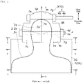
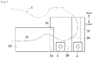
- the right-side head immobilization part 3A and the left-side head immobilization part 3B are joined by the respective inner facing surfaces 7a and 7b being butted. As shown in Figs. 3 to 5 , the right-side head immobilization part 3A and the left-side head immobilization part 3B have a greater thickness than for the shoulder immobilization part 3C. As shown in Fig. 4(A) , intercommunicable holder portions 2a, 2b are formed on each upper surface of the right-side head immobilization part 3A and the left-side head immobilization part 3B. The holder portions 2a and 2b have a shape along by the region from the lower side to the respective sides of the head of the patient 1A, and this region of the head tightly fits in the holder portions 2a and 2b.
- the shape of the specific site 1 of the patient 1A is not always symmetrical.
- the holder portions 2a, 2b do not necessarily have a symmetrical shape.
- the right-side head immobilization part 3A and the left-side head immobilization part 3B respectively comprise a mating portion 7c and a mating portion 7d at each shoulder-side end at which the right-side head immobilization part 3A and the left-side head immobilization part 3B fit the shoulder immobilization part 3C.
- the right-side head immobilization part 3A and the left-side head immobilization part 3B respectively comprise crown portions 7e, 7f, which are smaller in width than the mating portions 7c, 7d.
- the right-side head immobilization part 3A and the left-side head immobilization part 3B are connected and immobilized by two connectors 4.
- the connectors 4 are each composed of a bolt 4a and a nut 4b.
- Through-holes 7g for the bolts 4a to be inserted are present at two points in the lower part of each of the holder portions 2a, 2b of the right-side head immobilization part 3A and the left-side head immobilization part 3B and the lower part of the crown portions 7e, 7f.
- the shoulder immobilization part 3C comprises a holder portion 2c on the upper surface.
- the holder portion 2c has a shape along by the region from the lower part of the neck and the shoulders to both sides of the patient 1A, and the region of the neck and shoulders tightly fits in the holder portion 2c.
- the shoulder immobilization part 3C comprises at an end thereof closer to the head a recess 7h, into which the mating portions 7c, 7d of the right-side head immobilization part 3A and the left-side head immobilization part 3B fit.
- the right-side head immobilization part 3A, the left-side head immobilization part 3B, and the shoulder immobilization part 3C are connected and immobilized by the mating portions 7c, 7d of the parts 3A, 3B tightly mating with the recess 7h of the part 3C.
- the holder portions 2a, 2b, 2c of the parts 3A, 3B, and 3C become intercommunicable to thereby form a recessed portion (space) for supporting the specific site 1 (i.e., the holder portion 2).
- the head in the specific site 1 is supported while being sandwiched by the right-side head immobilization part 3A and the left-side head immobilization part 3B from left and right.
- the region from the neck to the shoulders are supported by the shoulder immobilization part 3C.
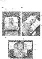
- Figs. 6(A) and 6(B) show that the head, neck, and shoulders (specific site 1) of the patient 1A lying on their back are immobilized by the medical immobilization device 10.
- the region from the lower part to both sides of the head of the patient 1A tightly fits in the holder portions 2a, 2b of the right-side head immobilization part 3A and the left-side head immobilization part 3B.
- the region from the lower part to both sides of the neck and shoulders of the patient 1A tightly fits in the holder portion 2c of the shoulder immobilization part 3C. This allows the medical immobilization device 10 to firmly immobilize the head, neck, and shoulders of the patient 1A with the upper part open.
- Figs. 7 and 8 show another embodiment of the present invention.
- an engagement recess 8a is formed in one of the facing surfaces 7a, 7b of the right-side head immobilization part 3A and the left-side head immobilization part 3B, and an engagement protrusion 8b that engages with the engagement recess 8a is formed in the other of the facing surfaces 7a, 7b to allow the linkage between the right-side head immobilization part 3A and the left-side head immobilization part 3B.
- an engagement recess 8c is formed in one of the facing surfaces of the right-side head immobilization part 3A and the shoulder immobilization part 3C, and an engagement protrusion 8d is formed in the other to allow the linkage between the parts 3A and 3C.
- an engagement recess 8e is formed in one of the facing surfaces of the left-side head immobilization part 3B and the shoulder immobilization part 3C, and an engagement protrusion 8f is formed in the other to allow the linkage between the parts 3B and 3C.
- Fig. 9 shows that the head, neck, and shoulders (specific site 1) of the patient 1A lying on their back are immobilized by the medical immobilization device 10 shown in Figs. 7 and 8 .
- the region from the lower part to both sides of the head of the patient 1A tightly fits in the holder portions 2a, 2b of the right-side head immobilization part 3A and the left-side head immobilization part 3B.
- the region from the lower part to both sides of the neck and shoulders of the patient 1A tightly fits in the holder portion 2c of the shoulder immobilization part 3C. This allows the medical immobilization device 10 to firmly immobilize the head, neck, and shoulders of the patient 1A with the upper part open.
- the medical immobilization device 10 of the present invention is produced by sequentially performing the steps shown in Fig. 10 .
- Performing the method shown in Fig. 10 provides the block 3 comprising the holder portion 2 in which at least the region from the lower part to both sides of the specific site 1 tightly fits.
- the medical immobilization device 10 shown in Fig. 10 is different from the medical immobilization device 10 described in the embodiments above, any medical immobilization device 10 described in the embodiments of the present invention above or in the embodiments described later can be produced by performing the steps shown in Fig. 10 .
- medical image data such as CT data or MRI data of the patient 1A are input to a manufacturing immobilization device support equipment 6 incorporating processing software (indicated by a rectangular frame in the figure).
- the manufacturing immobilization device support equipment 6 executes a shape extraction voxelization program to extract the shape (outer shape) of the specific site 1 of the body of the patient 1A from the medical image data and to perform voxelization.
- the extraction and voxelization of the outer shape of the specific site 1 are performed for each of the three regions comprising the regions immobilized by the parts 3A, 3B, and 3C.
- the medical image data is input by using appropriate data entry means.
- a medical image such as CT data is usually obtained beforehand in the hospital, and it thus makes sense to use such image data.
- other image data from which the body shape of the patient 1A can be extracted e.g., images obtained with a human body scanner
- the manufacturing immobilization device support equipment 6 comprises a data input/output unit, a storage unit, a display unit, an operation unit, and a control unit including a CPU for executing a predetermined program.
- the processing software is stored in the storage unit.
- the medical immobilization device 10 of this embodiment does not require that a person such as a radiological technologist perform the above-mentioned steps (1) to (4) for the production of the medical immobilization device 10 on site.
- the medical immobilization device 10 of this embodiment can be produced beforehand, for example, by outsourcing its production before treatment, and the patient 1A also does not have to endure suffering. These can lead to shortened treatment time or reduced burden on the patient 1A.
- immobilization may become insufficient depending on the operator's skill level in producing the fixtures, and an unintended clearance may form between the patient 1A and the fixture.
- the suction mat which is currently used as the bottom fixture, is deformed due to an air leak, the mat will no longer conform to the body shape of the patient 1A, and IMRT treatment cannot be continuously performed.
- the medical immobilization device 10 in this embodiment does not require work skill because the production of the block 3 is mechanized, and the completed medical immobilization device 10 perfectly fits the body shape of the patient 1A, improving immobilization precision from the current levels, and preventing problems such as air leak.
- each holder portion 2 is provided so as to surround the head of the patient 1A lying on their back from three directions.
- the holder portion 2 is not limited to these embodiments.
- the right-side head immobilization part 3A and the left-side head immobilization part 3B of the block 3 may be structured such that the top portion of the head is opened to provide a ventilation section 5, and such that the ventilation section 5 serves as an escape route for the hair.
- the holder portion 2 has a structure in which the region from the head to the shoulders of the patient 1A fits.
- the holder portion 2 is not limited to this structure.
- the holder portion 2 may be structured such that only the head and the shoulders of the patient 1A fit in, and such that the neck is only placed on the upper surface of the shoulder immobilization part 3C. In this manner, the shape and arrangement of the holder 2 can be altered in various ways.
- the holder portion 2 is structured such that the specific site 1 of the patient 1A (i.e., the region from the lower part to both sides of the head, neck, and shoulders) fits in the holder portion 2 with the entire surface of the region being tightly in contact.
- the holder portion 2 is structured not to come in contact with some region of the specific site 1 of the patient 1A.
- the region from the lower part to both sides of the head, neck, and shoulders fits in the holder portion 2, excluding the ventilation portion 5.
- each end on the shoulder side of the right-side head immobilization part 3A and the left-side head immobilization part 3B is notched from the side to the top, leaving the lower portion.
- the middle portion closer to the top of the head of the right-side head immobilization part 3A and the left-side head immobilization part 3B is notched from both sides toward the top, leaving the lower portion.
- the ventilation portion 5 is formed by a space between the right-side head immobilization part 3A and the shoulder immobilization part 3C and a space between the left-side head immobilization part 3B and the shoulder immobilization part 3C. Moreover, the ventilation portion 5 is also formed by the notch of the right-side head immobilization part 3A and the head-side notch of the left-side head immobilization part 3B.
- one of the facing surfaces 7a and 7b of the right-side head and left-side head immobilization parts 3A, 3B has the engagement recess 8a, and the other has the engagement recess 8b that engages with the engagement recess 8a, allowing the linkage between the parts 3A and 3B.
- the engagement recess 8c is formed in the center of the left-right direction of the plane of the shoulder immobilization part 3C facing the head immobilization parts 3A, 3B, and the engagement protrusions 8d, 8f are formed on the planes of the right-side and left-side head immobilization parts 3A, 3B, which are facing the shoulder immobilization part 3C.
- the engagement of the engagement protrusions 8d, 8f with the engagement recess 8c allows for the linkage between the part 3A and part 3C and between the part 3B and the part 3C.
- the cheeks of the patient 1A are soft. Even if the holder portion 2 supports such portions, the effect of immobilizing the body of the patient 1A is hardly obtained. Additionally, an immobilization device may not be attached due to changes in the body shape of the patient 1A caused by, for example, edema, during treatment. In this way, the body of the patient 1A is expected to have a plurality of sites in which an immobilization effect cannot be achieved. Additionally, if the holder portion 2 and the patient 1A are in contact with each other in many regions, air permeability decreases, and the patient 1A easily perspires, feeling increased discomfort.
- the ventilation part 5 is formed in the block 3 to the extent that the ventilation part 5 does not hinder the immobilization of the body. This saves materials, reduces manufacturing costs, shortens the working time if additional processing is performed with a processing machine in the step of Fig. 10(G) , and also shortens the working time in cutting with a processing machine if the material to be cut is provided with the ventilation portion 5 from the beginning.
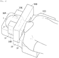
- Figs. 16 to 20 show yet another embodiment in which the block 3 comprises a head immobilization part 30A, a shoulder immobilization part 30C, and a jaw immobilization part 30B, which are connected to each other.
- the head immobilization part 30A comprises a right temporal region immobilization part 30D for immobilizing the right temporal region of the head, a left temporal region immobilization part 30E for immobilizing the left temporal region, and an occipital region immobilization part 30F for immobilizing the occipital region.
- the neck is immobilized by the shoulder immobilization part 30C at the part closer to the shoulders and by the head immobilization part 30A at the part closer to the head.
- the neck may be immobilized by either the head immobilization part 30A or the shoulder immobilization part 30C.
- the occipital region immobilization part 30F and the shoulder immobilization part 30C are connected in the longitudinal direction.
- the right and left temporal region immobilization parts 30D and 30E are each on the corresponding side of and connected to the occipital region immobilization part 30F.
- the jaw immobilization part 30B is connected at each end to the right and left temporal region immobilization parts 30D and 30E across the upper open portion between the right and left temporal region immobilization parts 30D and 30E.
- the jaw immobilization part 30B covers only a portion of the upper open part of the block 3, with the majority left open.
- the occipital region immobilization part 30F has a substantially rectangular parallelepiped outer shape and comprises a holder portion 20f on the upper surface.
- the holder portion 20f has a shape along by the lower surface region of the head and neck from the head to the neck of the specific site 1 of the patient 1A, and this region of the head and neck can fit in the holder portion 20f.
- the region of the specific site 1 that fits in the holder portion 20f is not strictly limited to the region along the lower surface of the head and neck.
- the region around it (e.g., a portion of the sides of the head or a portion of the top of the head) may fit in the holder portion 20f.
- the occipital region immobilization part 30F comprises a stepped portion 31 along by the longitudinal direction at each end of the upper surface in the width direction.
- the right and left temporal region immobilization parts 30D and 30E lock on the corresponding stepped portion 31.
- the stepped portions 31 each comprise a side surface 31a and a bottom surface 31b.
- the right and left temporal region immobilization parts 30D and 30E are each integrally formed so as to comprise a temporal portion 32 for immobilizing a temporal region, a neck portion 33 for immobilizing the neck, and an engagement portion 34 that is continuous with the lower edge of the temporal portion 32 and the neck portion 33 and that engages with the corresponding stepped portion 31 of the occipital region immobilization part 30F.
- a holder portions 32a, 33a are formed on each mutually facing inner surface of the temporal portion 32 and the neck portion 33 of the right and left temporal region immobilization parts 30D and 30E.
- the holder portions 32a and 33a communicate to form holder portions 20d, 20e.
- the right and left temporal region immobilization parts 30D and 30E have a symmetrical outer shape in the left-right direction.
- the shape of the holder portions 20d, 20e is not limited to a symmetrical shape.
- the holder portions 20d, 20e have a shape along by the region of the left or right side of the head and the left or right side of the neck from the head to the neck of the patient 1A. These regions of the head and neck can fit in the holder portions 20d, 20e.
- a through-hole 32b penetrating through the temporal portion 32 from the inner surface to the outer surface is located at the holder portion 32a.
- the through-hole 32b is located at a portion corresponding to the position of an ear of the patient 1A who is immobilized at the head by the right and left temporal region immobilization parts 30D and 30E. Each through-hole 32b prevents the ear from being pressed and the generation of unpleasant resonance.
- the right and left temporal region immobilization parts 30D and 30E are set to have a length shorter than the length of the occipital region immobilization part 30F.
- the right and left temporal region immobilization parts 30D and 30E are positioned closer to the shoulder side of the occipital region immobilization part 30F. This allows the top region of the head of the patient 1A to be opened without being covered by the block 3, secures ventilation, and reduces the discomfort felt by the patient 1A.
- the width L1, length L2, and height L3 of the engagement portion 34 of the right and left temporal region immobilization parts 30D and 30E are set to be substantially the same as the width L4, length L5, and height L6 of the stepped portion 31 of the occipital region immobilization part 30F.
- a holder portion 20c on the upper surface is formed at the shoulder immobilization part 30C.
- the holder portion 20c has a shape along by the region from the lower side to both sides of the shoulders of the patient 1A, and this region of the shoulders can fit in the holder portion 20c.
- a pair of rectangular parallelepiped projections 35 at ends on the head side of the shoulder immobilization part 30C is set at the shoulder immobilization part 30c.
- the distance L7 between the pair of projections 35 is set to be substantially the same as the width L8 of the occipital region immobilization part 30F.
- the occipital region immobilization part 30F tightly fit at ends on the shoulder side between the pair of projections 35, thereby connecting and immobilizing the shoulder immobilization part 30C and the occipital region immobilization part 30F.
- the thickness L9 of the projections 35 is equal to the thickness L10 that is from the lower surface of the occipital region immobilization part 30F to the bottom surface of the stepped portion 31.
- the jaw immobilization part 30B has an arch shape with a downward opening and comprises an immobilization portion 36 having a holder portion 20b formed on the lower surface, and a pair of leg portions 37 on either end of the immobilization portion 36.
- the holder portion 20b has a shape along by the region comprising the top surface and both sides of the jaw, the lower surface of the jaw, and the top surface closer to the head and both sides of the neck of the patient 1A. These regions of the body can fit in the holder portion 20b.
- the distance L11 between the pair of leg portions 37 is substantially equal to the distance L7 between the pair of projections 35 of the shoulder immobilization part 30C.
- the shape of the bottom surface of the pair of leg portions 37 is substantially the same rectangular shape as that of the upper surface of the pair of projections 35 of the shoulder immobilization part 30C.
- the height L12 of each leg portion 37 is substantially equal to the thickness L13 of the neck portion 33 of the right and left temporal region immobilization parts 30D and 30E.
- the leg portions 37 of the jaw immobilization part 30B tightly fits each neck portion 33 of the right and left temporal region immobilization parts 30D and 30E, thereby connecting the jaw immobilization part 30B to the right and left temporal region immobilization parts 30D and 30E.
- the block 3 in this embodiment is assembled according to the following procedure.
- the end closer to the shoulders of the occipital region immobilization part 30F is tightly fit in the portion between the pair of projections 35 of the shoulder immobilization part 30C to connect the shoulder immobilization part 30C to the occipital region immobilization part 30F.
- each engagement portion 34 of the right and left temporal region immobilization parts 30D and 30E is locked on the corresponding stepped portion 31 of the occipital region immobilization part 30F, and then the jaw immobilization part 30B is attached from above across the upper open portion of the occipital region immobilization part 30F and the right and left temporal region immobilization parts 30D and 30E.
- each leg portion 37 of the jaw immobilization part 30B comes in contact with the upper surface of the corresponding projection 35 of the shoulder immobilization part 30C.
- the inner surface of each leg portion 37 of the jaw immobilization part 30B presses each engagement portion 39 of the right and left temporal region immobilization parts 30D and 30E against the side surface 31a of each stepped portion 31 of the occipital region immobilization part 30F.
- the parts 30B, 30C, 30D, 30E, and 30F thus form a recessed portion for tightly supporting the specific site 1, i.e., the holder portion 2.
- Fig. 20 shows that the head, neck, and shoulders of the patient 1A lying on their back are immobilized by the medical immobilization device 10.
- the lower region of the head and the lower region of the neck of the patient 1A tightly fit in the holder portion 20f of the occipital region immobilization part 30F.
- Both sides of the head and both sides of the neck of the patient 1A tightly fit in the holder portions 20d, 20e of the right and left temporal region immobilization parts 30D and 30E.
- the shoulders of the patient 1A tightly fit in the holder portion 20c of the shoulder immobilization part 30C.
- the jaw of the patient 1A tightly fits in the holder portion 20b of the jaw immobilization part 30B.
- the upper edge 2d of the portion of each holder portion 20d, 20e of the parts 30D, 30E for immobilizing the temporal region is located above the center in the up-and-down direction of the head. This allows the medical immobilization device 10 to firmly immobilize the head, neck, and jaw of the patient 1A with the majority of the upper portion of the block 3 being open.
- the jaw of the patient 1A is immobilized firmly by the jaw immobilization part 30B.
- the block 3 has the upper portion open except for the part in which the jaw immobilization part 30B is present, the patient 1A is less stressed, without feeling suffocated or having an oppressive feeling.
- the right and left temporal region immobilization parts 30D and 30E located closer to the shoulders of the patient 1A with the top region of the patient 1A not covered by the block 3 ensures breathability.
- Figs. 21 to 24 show yet another embodiment.
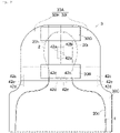
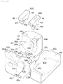
- the block 3 comprises the head immobilization part 30A, the shoulder immobilization part 30C, the jaw immobilization part 30B, and a forehead immobilization part 30G that are connected to each other.
- the head immobilization part 30A comprises a right-side head immobilization part 30H and a left-side head immobilization part 301 that are connected to each other.
- the right-side and left-side head immobilization parts 30H and 301 are each integrally formed of a side portion 40 and a lower portion 41.
- a holder portion 40a is formed at the inner facing surface of each side portion 40 .
- the holder portion 40a has a shape along by the region of the left or right side of the head of the patient 1A. This region of the head can fit in the holder portion 40a.
- a through-hole 40c penetrating the side portion 40 from the inner surface to the outer surface is also formed at the holder portion 40acomprises.
- the holder portion 41a is formed on the upper surface of each lower portion 41.
- the holder portion 41a has a shape along by the region of the lower surface of the left side or right side of the head of the patient 1A.
- This region of the head can fit in the holder portion 41a.
- These holder portions 40a, 41a communicate with each other to form a holder portion 20h or 20i.
- the right-side and left-side head immobilization parts 30H and 301 each have a symmetrical outer shape in the left-right direction.
- the shape of the holder portions 20h, 20i is not limited to a symmetrical shape.
- the right-side and left-side head immobilization parts 30H and 301 each have a thickness greater than the thickness of the shoulder immobilization part 30C.
- the side portion 40 is formed at a position closer to the shoulders on the upper surface a recess 40b on which a corresponding end of the jaw immobilization part 30B is locked.
- a recess 40b on which an end of the forehead immobilization part 30G is locked is formed of the side portion 40 at a position closer to the head top.
- An engagement recess 42a is respectively formed at the mutually facing surfaces of the lower portions 41 of the parts 30H, 30I.
- a connecting member 42b is tightly fit into each engagement recess 42a, thereby connecting the right-side and left-side head immobilization parts 30H and 301.
- An engagement recess 42c and an engagement recess 42d are respectively formed on the surface of the right-side head immobilization part 30H facing the shoulder immobilization part 30C and on the surface of the shoulder immobilization part 30C facing the right-side head immobilization part 30H.
- the engagement recess 42c and the engagement recess 42d are also respectively formed on the surface of the left-side head immobilization part 301 facing the shoulder immobilization part 30C and on the surface of the shoulder immobilization part 30C facing the left-side head immobilization part 301.
- the engagement recess 42c at two positions on the left and right are formed at the right-side and left-side head immobilization parts 30H and 301.
- Three engagement recesses 42d corresponding to the engagement recesses 42c at the center and two positions on the left and right are formed at the shoulder immobilization part 30C.
- the parts 30H, 301, and 30C are butted against each other at their facing surfaces, and a connecting member 42e is tightly fit into each engagement recess 42c, 42d to connect the right-side head immobilization part 30H to the shoulder immobilization part 30C, and to connect the left-side head immobilization part 301 to the shoulder immobilization part 30C.
- Holder portion 20c are formed on the upper surface of the shoulder immobilization part 30Ce.
- the holder portion 20c has a shape along by the region from the lower part to both sides of the shoulders and from the lower part closer to the shoulders to both sides of the neck of the patient 1A. This region of the shoulders and neck can fit in the holder portion 20c.
- the jaw immobilization part 30B is substantially T-shaped as viewed from the shoulder side, and comprises a mating portion 43 that fits in between the right-side and left-side head immobilization parts 30H and 301, and flange portions 44 that extend from the upper end portion of the mating portion 43 toward the left and right, and that are locked into each recess 40b on the upper surface of the right-side and left-side head immobilization parts 30H and 301.
- a holder portion 20b is formed on the lower surface of the mating portion 43 .
- the holder portion 20b is formed in a shape along by the region from the upper surface to both sides of the jaw and the upper surface closer to the head to both sides of the neck of the patient 1A.
- the width of the mating portion 43 is set to be substantially equal to the distance between the side portions 40 of the right-side and left-side head immobilization parts 30H and 301. Fitting the mating portion 43 into the part between the right-side and left-side head immobilization parts 30H and 301 allows the outer surface of the mating portion 43 and the inner surface of the head immobilization part 30A to tightly fit each other, thereby connecting the jaw immobilization part 30B to the right-side and left-side head immobilization parts 30H and 301.
- the forehead immobilization part 30G is substantially T-shaped as viewed from the shoulder side, and comprises a mating portion 45 that fits in between the right-side and left-side head immobilization parts 30H and 301, and flange portions 46 that extend from the upper end portion of the mating portion 45 toward the left and right, and that are locked into each recess 40b on the upper surface of the right-side and left-side head immobilization parts 30H and 301.
- a holder portion 20g are formed on the lower surface of the mating portion 45 .
- the holder portion 20g is formed in a shape along by the region from the upper surface of the forehead to the upper surface of the top of the head of the patient 1A. This region of the forehead and the top of the head can fit in the holder portion 20g.
- the width of the mating portion 45 is set to be substantially equal to the distance between the side portions 40 of the right-side and left-side head immobilization parts 30H and 301. Fitting the mating portion 45 into the part between the right-side and left-side head immobilization parts 30H and 301 allows the outer surface of the mating portion 45 and the inner surface of the head immobilization part 30A to tightly fit each other, thereby connecting the forehead immobilization part 30G to the right-side and left-side head immobilization parts 30H and 301.
- the holder portions 20b, 20c, 20g, 20h, and 20i of the parts 30B, 30C, 30G, 30H, and 301 form a recessed portion for tightly supporting the specific site 1, i.e., the holder portion 2.
- Fig. 24 shows that the head, neck, and shoulders of the patient 1A are immobilized by the medical immobilization device 10 with the patient 1A lying on their back.
- the region from the lower part to both sides of the head and neck of the patient 1A tightly fit in the holder portions 20h, 20i of the right-side and left-side head immobilization parts 30H and 301.
- the region from the lower part to both sides of the shoulders of the patient 1A tightly fit in the holder portion 20c of the shoulder immobilization part 30C.
- the region from the upper surface of the jaw to the upper surface of the neck closer to the head of the patient 1A tightly fits in the holder portion 20b of the jaw immobilization part 30B.
- the upper edge 2d of each holder portion 20h, 20i i.e., the upper edge 2d of the portion that comes in contact with each side of the patient's head) is located above the center in the up-and-down direction of the head. This allows the medical immobilization device 10 to firmly immobilize the head, neck, jaw, and forehead of the patient 1A with the upper portion of the block 3 being partly open.
- the jaw and the forehead of the patient 1A are immobilized firmly by the jaw immobilization part 30B and the forehead immobilization part 30G. This limits the movement of the patient 1A, such as shaking the head side to side, opening the mouth, or raising the chin. Additionally, because the block 3 has the upper portion open except for the part in which the jaw immobilization part 30B and the forehead immobilization part 30G are present, the patient 1A does not feel suffocated or have an oppressive feeling.
- the region from the head to the shoulders of the patient 1A is determined to be the specific site 1, and at least the region from the lower part to both sides of the specific site 1, preferably a region beyond this region, is set to fit in the holder 2.
- the medical immobilization device 10 of the present invention is not limited to this embodiment.
- other regions of the patient 1A or the entire body may be set to be a specific site 1, and the medical immobilization device 10 may be structured such that at least the region from the lower part to both sides of the specific site 1, preferably a region beyond this region, fit in the holder 2.
Landscapes
- Health & Medical Sciences (AREA)
- Engineering & Computer Science (AREA)
- Biomedical Technology (AREA)
- Life Sciences & Earth Sciences (AREA)
- Public Health (AREA)
- Pathology (AREA)
- Veterinary Medicine (AREA)
- Animal Behavior & Ethology (AREA)
- General Health & Medical Sciences (AREA)
- Nuclear Medicine, Radiotherapy & Molecular Imaging (AREA)
- Radiology & Medical Imaging (AREA)
- Physics & Mathematics (AREA)
- Biophysics (AREA)
- Heart & Thoracic Surgery (AREA)
- Medical Informatics (AREA)
- Molecular Biology (AREA)
- Surgery (AREA)
- Radiation-Therapy Devices (AREA)
- Orthopedics, Nursing, And Contraception (AREA)
Abstract
Description
- The present invention relates to a medical immobilization device suitable for immobilizing a patient or subject (collectively referred to as a "patient" below) when performing, for example, radiotherapy or diagnostic imaging such as MRI.
- In this specification, the term "up and down" for a patient lying on their back has a different meaning from up and down for a standing patient. The term "up and down" used here means that the side facing the patient's abdomen is "up" and the side facing the patient's back is "down."
- IMRT (intensity-modulated radiation therapy) is one of the radiotherapies for cancer. IMRT divides the radiation applied to a patient from multiple directions into small beams and appropriately changes the irradiation shape of each beam to increase the irradiation dose to the tumor area, thereby improving the tumor control rate. IMRT also divides the irradiation time into several days (repeated irradiation) to minimize exposure to normal tissue and reduce complications.
- IMRT uses a computer-controlled device that can adjust the spot of radiation irradiation with high precision. However, the treatment effect may be impaired or the risk of complications may be heightened, for example, if the patient under irradiation moves and the irradiation position shifts, or if the position of the patient under re-irradiation shifts. Thus, the patient under irradiation must be firmly immobilized.
- Conventionally, a patient under irradiation is immobilized by using a top fixture and a bottom fixture that sandwich the patient lying on their back from the upper and lower directions. As shown in
PTL 1, the top fixture is shaped by covering a patient lying on their back with a perforated resin mask that is softened beforehand by heating, by pressing it from above, and cooling to solidify it for conformity to the shape of the patient. For the bottom fixture, as shown inPTL 2, a suction mat is often used in the following manner. A patient is laid on their back on an airtight mat that contains beads and that is fixed to a treatment table, and air in the mat is removed to allow the mat to conform to the shape of the patient. To immobilize a patient, the two fixtures are connected so that the patient's body is tightly sandwiched from above and below. - Additionally, as shown in
PTL 3, a fixture that does not use the above resin mask and suction mat is also proposed, which is produced by embedding a patient in frothed polyurethane foam before it softens. -
- PTL 1: Patent No.
6563737 - PTL 2: Patent No.
6619609 - PTL 3:
JPH03-74592A - Although a certain degree of reproducibility of the shape can be achieved when a patient lying on their back is immobilized from the upper side by using the method disclosed in
PTL 1, the patient must bear a great mental and physical burden during production and treatment by the method. Immobilizing the body from the lower side as disclosed inPTL 2 is more likely to reduce such burdens. However, the method using a suction mat is unsatisfactory in immobilization performance due to its difficulty in reproducing the shape of the patient because of the complexity of the shape formation procedure coupled with the mat material. As noted above, conventional immobilization methods impose a great burden on the patient because the patient is immobilized mainly by being covered from above with a top fixture that reproduces the shape of the patient. Conventional immobilization methods also have a decreased overall immobilization precision due to the lack of shape reproducibility precision by the bottom fixture. - Additionally, in the series of the fixtures proposed by
PTL 3, the following problems arise: the fixtures impose a great burden on the patient because it is necessary to restrain the movement of the patient until the foam solidifies; production of the fixtures is very complicated and places a heavy burden on the person who produces them; and the strength of the completed foam fixture is weak (brittle), and breaks during a series of treatments. - The present invention was made in consideration of the matters described above. An object of the invention is to provide a medical immobilization device that is capable of firmly immobilizing a patient; that contributes to the improvement of immobilization precision, reproducibility, and workability for immobilization; and that also contributes to reducing the burden on the patient.
- To achieve the object, the medical immobilization device according to the present invention is configured to immobilize a specific site of a patient with the patient lying on their back, the medical immobilization device comprising a block made of a material that allows radiation to pass through,
- the block comprising a holder portion in which at least a region from the lower surface to both sides of the specific site tightly fits,
- the block having all or part of the upper side thereof open.
- In a preferable embodiment, the upper edge of a portion of the holder portion that comes into contact with the sides of the specific site is located above the center of the specific site in the up-and-down direction.
- In a preferable embodiment, the region from the lower surface to both sides of the specific site fits in the holder portion with the entire surface of the region being tightly in contact.
- The holder portion may comprise a ventilation portion with which the specific site does not come into contact, and the region from the lower surface to both sides of the specific site tightly fits in the holder portion excluding the ventilation portion.
- In a preferable embodiment, the block comprises a plurality of parts that are connected to each other.
- In a preferable embodiment, the block comprises a head immobilization part and a shoulder immobilization part, the head immobilization part and the shoulder immobilization part being connected to each other, and the head immobilization part comprises a right-side head immobilization part for immobilizing the right-side head and a left-side head immobilization part for immobilizing the left-side head.
- In a more preferable embodiment, the block comprises a head immobilization part for immobilizing the head, a shoulder immobilization part for immobilizing the shoulders, and at least either a jaw immobilization part for immobilizing the jaw or a forehead immobilization part for immobilizing the forehead, or both,
- the head immobilization part, the shoulder immobilization part, and at least either the jaw immobilization part for immobilizing a jaw or the forehead immobilization part for immobilizing a forehead, or both are connected to each other,
- the head immobilization part comprises at least a right-side head immobilization part for immobilizing the right-side head and a left-side head immobilization part for immobilizing the left-side head, and
- at least either the jaw immobilization part or the forehead immobilization part, or both are connected at each end to the right-side head immobilization part and the left-side head immobilization part across the upper open portion between the right-side head immobilization part and the left-side head immobilization part.
- In a preferable embodiment, the block comprises the head immobilization part, the shoulder immobilization part, and the jaw immobilization part, the head immobilization part, the shoulder immobilization part, and the jaw immobilization part being connected to each other,
- the head immobilization part comprises a right temporal region immobilization part for immobilizing the right temporal region, a left temporal region immobilization part for immobilizing the left temporal region, and an occipital region immobilization part for immobilizing the occipital region,
- the occipital region immobilization part and the shoulder immobilization part are connected in the longitudinal direction,
- the left temporal region immobilization part and the right temporal region immobilization part are respectively connected to the left side and the right side of the occipital region immobilization part, and
- the jaw immobilization part is connected at each end to the left temporal region immobilization part and the right temporal region immobilization part across the upper open portion between the left temporal region immobilization part and the right temporal region immobilization part.
- In another preferable embodiment, the block comprises the head immobilization part, the shoulder immobilization part, the jaw immobilization part, and the forehead immobilization part, the head immobilization part, the shoulder immobilization part, the jaw immobilization part, and the forehead immobilization part being connected to each other,
- the head immobilization part and the shoulder immobilization part are connected in the longitudinal direction, and
- the jaw immobilization part and the forehead immobilization part are connected at each end to the left head immobilization part and the right head immobilization part across the upper open portion between the right-side head immobilization part and the left-side head immobilization part.
- The present invention provides a medical immobilization device that is capable of firmly immobilizing a patient; that contributes to the improvement of immobilization precision, reproducibility, and workability for immobilization; and that also contributes to reducing the burden on the patient.
- The medical immobilization device in a preferable embodiment firmly immobilizes the specific site of a patient by the holder portion that has a depth of a half or more of the thickness of the specific site, and also improves immobilization precision and reproducibility due to immobilization by the deep holder portion. Additionally, the mental and physical burden on the patient is reduced by eliminating (or minimizing) the immobilization of the patient lying on their back from above, and mainly by immobilizing the patient from below by the holder portion.
- The medical immobilization device in a preferable embodiment makes it easier for the block to have a high degree of flexibility in shape due to the structure of the block composed of a plurality of parts.
- The medical immobilization device in a more preferable embodiment can immobilize the head by the occipital region immobilization part and the temporal region immobilization parts and can immobilize from above at least either the jaw or the forehead of the patient by comprising at least either the jaw immobilization part or the forehead immobilization part, thereby firmly immobilizing the head and the neck of the patient (specific site) without covering the patient from above.
-
-
Fig. 1 is an illustration of a radiotherapy machine in which the medical immobilization device of the present invention is used. -
Fig. 2 is a plane view of an embodiment of the present invention. -
Fig. 3 is a side view of the embodiment shown inFig. 2 . -
Fig. 4(A) is a sectional view taken along line A-A inFig. 2 . -
Fig. 4(B) is a sectional view taken along line B-B inFig. 2 . -
Fig. 4(C) is a sectional view taken along line C-C inFig. 2 . -
Fig. 5 is a sectional view taken along line D-D inFig. 2 . -
Fig. 6(A) and Fig. 6(B) are illustrations showing a state in which a patient's head and shoulders are immobilized by using the embodiment shown inFig. 2 . -
Fig. 7 is a plane view showing another embodiment of the present invention. -
Fig. 8 is a side view of the embodiment shown inFig. 7 . -
Fig. 9 is illustrations showing a state in which a patient's head and shoulders are immobilized by using the embodiment shown inFig. 7 . -
Fig. 10 is an illustration showing a production method for the medical immobilization device of the present invention. -
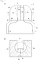
Fig. 11 is views showing another embodiment of the present invention.Fig. 11(A) is a plane view, andFig. 11(B) is a sectional view taken along line E-E. -
Fig. 12(A) is a view showing a basic shape for use in the production of the embodiment shown inFig. 11 .Fig. 12(B) is an illustration showing a state in which a patient's head and shoulders are immobilized by using the embodiment produced from the basic shape ofFig. 12(A) . -
Fig. 13 is a plane view showing another embodiment of the present invention. -
Fig. 14 is a sectional view taken along line F-F inFig. 13 . -
Fig. 15 is an illustration showing a state in which a patient's head and shoulders are immobilized by using the embodiment shown inFig. 13 . -
Fig. 16 is a plane view showing another embodiment of the present invention. -
Fig. 17 is a side view of the embodiment shown inFig. 16 . -
Fig. 18 is an exploded perspective view of the embodiment shown inFig. 16 . -
Fig. 19(A) is a perspective view showing a left temporal region immobilization part.Fig. 19(B) is a perspective view showing an occipital region immobilization part.Fig. 19(C) is a perspective view showing a jaw immobilization part. -
Fig. 20 is an illustration showing a state in which a patient's head and shoulders are immobilized by using the embodiment shown inFig. 16 . -
Fig. 21 is a plane view of another embodiment of the present invention. -
Fig. 22 is a side view of the embodiment shown inFig. 21 . -
Fig. 23 is an exploded perspective view of the embodiment shown inFig. 21 . -
Fig. 24 is an illustration showing a state in which a patient's head and shoulders are immobilized by using the embodiment shown inFig. 21 . - As shown in
Fig. 1 , amedical immobilization device 10 according to the present invention is used on a support table 101 by which apatient 1A lying on their back is supported in aradiotherapy equipment 100. Themedical immobilization device 10 is positioned and immobilized at a predetermined position on the support table 101 by a holding mechanism (not shown). Embodiments of the present invention will be described with reference to drawings. - The
medical immobilization device 10 shown inFigs. 2 to 5 , is for immobilizing thespecific site 1 of the body of thepatient 1A, for example, during radiation in IMRT, and is formed of ablock 3 made of a material that allows radiation to pass through. Theblock 3 has appropriate elasticity, and comprises aholder portion 2 into which at least a region from the lower surface to both sides of thespecific site 1 of the body of thepatient 1A lying on their back fits with the entire surface of the region being tightly in contact. In theholder portion 2, at least a portion of theupper edge 2d of the portion that comes into contact with the sides of thespecific site 1 is located above the center of thespecific site 1 in the up-and-down direction. - The phrase "the center of the
specific site 1 in the up-and-down direction" as used here means, as shown inFig. 4(A) , a height position P3 that is a half of the maximum height of thespecific site 1 of thepatient 1A in a natural posture lying on a flat plane P1, i.e., height d that is from the plane P1 to a top P2 (for example, the top of the nose in the case of the head). - Preferably, at least a portion of the
upper edge 2d of the portion of the holder portion that comes into contact with the sides of thespecific site 1 falls within the range of two-fifths of the height d that goes downward from the top P2 of thespecific site 1. This immobilizes thespecific site 1 more reliably. In the embodiments shown inFigs. 2 to 5 , the entireupper edge 2d of both sides of the portion of theholder portion 2 that come into contact with the head is located above the height position P3 that is in the center of thespecific site 1 in the up-and-down direction. - The
block 3 has all or part of the upper side open so as not to cover the upper side of the patient. Theblock 3 is preferably structured so as to have the upper part of thespecific site 1 mostly open when thespecific site 1 fits in theholder portion 2. - The
medical immobilization device 10 of the present embodiment is intended to firmly immobilize mainly the head and neck of thepatient 1A in a natural posture lying on their back. In themedical immobilization device 10 of the present embodiment, the region from the head to the shoulders of thepatient 1A is thespecific site 1, and at least the lower side fits in theholder portion 2. - In the following embodiments, the
specific site 1 means, but is not limited to, the head, neck, and shoulders of thepatient 1A. A "shoulder" is the upper portion of the body part at which the arm is connected to the torso, and the part from there to the base of the neck. The "neck" is the part between the head and shoulders. The "head" is the part above the neck and is divided into the occipital region that is the lower part; the left and right temporal regions, which are the left and right side parts; the parietal region, which is the top part of the head; the jaw part; and the forehead part. - Unless otherwise defined, the "left-right direction" refers to the left-right direction as seen from the
patient 1A lying on their back on the support table 101, and the "up-and-down direction" refers to the direction between the ventral side (upward direction) and the dorsal side (downward direction) of the patient lying on their back on the support table 101. The "longitudinal direction" refers to the direction perpendicular to the up-and-down direction or the left-right direction. The direction toward the head of thepatient 1A is the head side, and the direction opposite the head side is the shoulder side. The terms "thickness" and "height" refer to the dimension (distance) in the up-and-down direction, and the term "width" refers to the dimension (distance) in the left-right direction. The term "length" refers to the dimension (distance) in the longitudinal direction. - The thus-structured
medical immobilization device 10 of this embodiment can firmly immobilize thespecific site 1 of thepatient 1A by, so to speak, theholder portion 2 with a depth of a half or more of the thickness of, in particular, the head of thespecific site 1. Immobilization by using thedeep holder portion 2 can also improve immobilization precision and reproducibility. - Additionally, when all or part of the upper side of the
block 3 is released allowing thepatient 1A lying on their back to not (or barely) be immobilized from the upper side but be only immobilized by theholder portion 2 from the lower side, the mental and physical burden on thepatient 1A can be reduced. This effect is particularly useful for aclaustrophobic patient 1A because the entire facial area is not covered by theblock 3. - Moreover, the immobilization of the
specific site 1 of thepatient 1A is basically complete only when thespecific site 1 fits in theholder portion 2. Thus, themedical immobilization device 10 of this embodiment can also improve the workability of immobilization. - The
block 3 is made from a material that allows radiation to pass through. Such materials include foamed resin materials such as urethane foam and Styrofoam, carbon materials (CFRP), and wood. From the standpoint of ease of processing, foamed resin materials are particularly preferable. - The
block 3 may be formed of a single component, or may be formed of a plurality of parts (block parts) that can be connected to each other, for example, for the purpose of having a high degree of flexibility in shape of theblock 3. - In this embodiment, as shown in
Fig. 2 , theblock 3 is composed of two parts for immobilizing the head (i.e., a right-sidehead immobilization part 3A for immobilizing the right part of the head and a left-side head immobilizationpart 3B for immobilizing the left part of the head) and ashoulder immobilization part 3C for immobilizing the shoulders, which are all connected. The neck of thepatient 1A may be immobilized by the head immobilization parts or theshoulder immobilization part 3C. The neck portion near the shoulders may be immobilized by theshoulder immobilization part 3C, and the neck portion near the head may be immobilized by the head immobilization parts. - The right-side
head immobilization part 3A and the left-side head immobilizationpart 3B are joined by the respective inner facing surfaces 7a and 7b being butted. As shown inFigs. 3 to 5 , the right-sidehead immobilization part 3A and the left-side head immobilizationpart 3B have a greater thickness than for theshoulder immobilization part 3C. As shown inFig. 4(A) ,intercommunicable holder portions head immobilization part 3A and the left-side head immobilizationpart 3B. Theholder portions patient 1A, and this region of the head tightly fits in theholder portions - Although the right-side
head immobilization part 3A and the left-side head immobilizationpart 3B have a symmetrical shape, the shape of thespecific site 1 of thepatient 1A is not always symmetrical. Thus, theholder portions - The right-side
head immobilization part 3A and the left-side head immobilizationpart 3B respectively comprise amating portion 7c and amating portion 7d at each shoulder-side end at which the right-sidehead immobilization part 3A and the left-side head immobilizationpart 3B fit theshoulder immobilization part 3C. On the opposite side of themating portions head immobilization part 3A and the left-side head immobilizationpart 3B respectively comprisecrown portions mating portions - As shown in
Figs. 2 ,3 , and4(A) , the right-sidehead immobilization part 3A and the left-side head immobilizationpart 3B are connected and immobilized by twoconnectors 4. Theconnectors 4 are each composed of abolt 4a and anut 4b. Through-holes 7g for thebolts 4a to be inserted are present at two points in the lower part of each of theholder portions head immobilization part 3A and the left-side head immobilizationpart 3B and the lower part of thecrown portions - As shown in
Figs. 3 ,4(B) ,4(C) , and5 , theshoulder immobilization part 3C comprises aholder portion 2c on the upper surface. Theholder portion 2c has a shape along by the region from the lower part of the neck and the shoulders to both sides of thepatient 1A, and the region of the neck and shoulders tightly fits in theholder portion 2c. Theshoulder immobilization part 3C comprises at an end thereof closer to the head arecess 7h, into which themating portions head immobilization part 3A and the left-side head immobilizationpart 3B fit. The right-sidehead immobilization part 3A, the left-side head immobilizationpart 3B, and theshoulder immobilization part 3C are connected and immobilized by themating portions parts recess 7h of thepart 3C. - With the right-side
head immobilization part 3A and the left-side head immobilizationpart 3B connected to theshoulder immobilization part 3C, theholder portions parts specific site 1 is supported while being sandwiched by the right-sidehead immobilization part 3A and the left-side head immobilizationpart 3B from left and right. The region from the neck to the shoulders are supported by theshoulder immobilization part 3C. -
Figs. 6(A) and 6(B) show that the head, neck, and shoulders (specific site 1) of thepatient 1A lying on their back are immobilized by themedical immobilization device 10. The region from the lower part to both sides of the head of thepatient 1A tightly fits in theholder portions head immobilization part 3A and the left-side head immobilizationpart 3B. The region from the lower part to both sides of the neck and shoulders of thepatient 1A tightly fits in theholder portion 2c of theshoulder immobilization part 3C. This allows themedical immobilization device 10 to firmly immobilize the head, neck, and shoulders of thepatient 1A with the upper part open. -
Figs. 7 and8 show another embodiment of the present invention. In this embodiment, in place of theconnectors 4, anengagement recess 8a is formed in one of the facingsurfaces head immobilization part 3A and the left-side head immobilizationpart 3B, and anengagement protrusion 8b that engages with theengagement recess 8a is formed in the other of the facingsurfaces head immobilization part 3A and the left-side head immobilizationpart 3B. In this embodiment, anengagement recess 8c is formed in one of the facing surfaces of the right-sidehead immobilization part 3A and theshoulder immobilization part 3C, and anengagement protrusion 8d is formed in the other to allow the linkage between theparts engagement recess 8e is formed in one of the facing surfaces of the left-side head immobilizationpart 3B and theshoulder immobilization part 3C, and anengagement protrusion 8f is formed in the other to allow the linkage between theparts -
Fig. 9 shows that the head, neck, and shoulders (specific site 1) of thepatient 1A lying on their back are immobilized by themedical immobilization device 10 shown inFigs. 7 and8 . The region from the lower part to both sides of the head of thepatient 1A tightly fits in theholder portions head immobilization part 3A and the left-side head immobilizationpart 3B. The region from the lower part to both sides of the neck and shoulders of thepatient 1A tightly fits in theholder portion 2c of theshoulder immobilization part 3C. This allows themedical immobilization device 10 to firmly immobilize the head, neck, and shoulders of thepatient 1A with the upper part open. - The
medical immobilization device 10 of the present invention is produced by sequentially performing the steps shown inFig. 10 . Performing the method shown inFig. 10 provides theblock 3 comprising theholder portion 2 in which at least the region from the lower part to both sides of thespecific site 1 tightly fits. Although themedical immobilization device 10 shown inFig. 10 is different from themedical immobilization device 10 described in the embodiments above, anymedical immobilization device 10 described in the embodiments of the present invention above or in the embodiments described later can be produced by performing the steps shown inFig. 10 .
Step (1): First, as shown inFigs. 10(A) and 10(B) , medical image data (DICOM format) such as CT data or MRI data of thepatient 1A are input to a manufacturing immobilizationdevice support equipment 6 incorporating processing software (indicated by a rectangular frame in the figure). The manufacturing immobilizationdevice support equipment 6 executes a shape extraction voxelization program to extract the shape (outer shape) of thespecific site 1 of the body of thepatient 1A from the medical image data and to perform voxelization. In this embodiment, because thespecific site 1 of the body of thepatient 1A is immobilized by the three parts (the right-sidehead immobilization part 3A, the left-side head immobilizationpart 3B, and theshoulder immobilization part 3C), the extraction and voxelization of the outer shape of thespecific site 1 are performed for each of the three regions comprising the regions immobilized by theparts - The medical image data is input by using appropriate data entry means. When the
patient 1A undergoes IMRT, a medical image such as CT data is usually obtained beforehand in the hospital, and it thus makes sense to use such image data. Alternatively, other image data from which the body shape of thepatient 1A can be extracted (e.g., images obtained with a human body scanner) may be used instead. The manufacturing immobilizationdevice support equipment 6 comprises a data input/output unit, a storage unit, a display unit, an operation unit, and a control unit including a CPU for executing a predetermined program. The processing software is stored in the storage unit. - Step (2): As shown in
Fig. 10(C) , basic shape data (e.g., data in STL format such as 3D CAD) of themedical immobilization device 10 in this embodiment are input (imported) to the manufacturing immobilizationdevice support equipment 6. The manufacturing immobilizationdevice support equipment 6 executes a voxelization program to perform voxelization of the basic shape data. This step (2) may be performed, for example, before step (1). The basic shape data refer to 3D data illustrating the outer shape of the plurality of parts of theblock 3 before theholder portion 2 is formed. In this embodiment, the basic shape data are 3D data of the outer shape corresponding to the right-sidehead immobilization part 3A, the left-side head immobilizationpart 3B, and theshoulder immobilization part 3C.Fig. 12(A) , which is explained later, shows a basic shape for use in the production of the embodiment shown inFig. 12(B) . InFig. 12(A) , the same reference numerals as those of the parts of theblock 3 that has theholder portion 2 formed are also added to the plurality of the parts. - Step (3): After steps (1) and (2), as shown in
Figs. 10(D) and 10(E) , the manufacturing immobilizationdevice support equipment 6 executes a data fusion operation program and subtracts the shape of thepatient 1A from the basic shape data of themedical immobilization device 10 to obtain the shape of theholder portion 2, thereby completing 3D shape data for each part of themedical immobilization device 10 tailored for the body shape of thepatient 1A. Specifically, in this embodiment, the suitable shape of theholder portion 2 varies depending on the body shape of thepatient 1A, and the shape of theholder portion 2 that matches the body shape of thepatient 1A is given in the completed shape data. Of course, in this customization, the shape of the portion other than theholder portion 2 in themedical immobilization device 10 may be appropriately adjusted. - Step (4): After step (3), as shown in
Figs. 10(F) and 10(G) , the completed shape data are converted into an appropriate format (e.g., STL format) and output to a processing machine (e.g., a cutting machine or a 3D printer), which is not shown, followed by producing themedical immobilization device 10 by using the processing machine. The processing machine for use may be, for example, a machine that cuts out amedical immobilization device 10 of a predetermined shape from a block made of Styrofoam; or, for example, a machine that performs additional processing that laminates a CFRP material to form amedical immobilization device 10 of a predetermined shape. Each part of themedical immobilization device 10 may also be produced by using a processing machine. For example, only some parts of themedical immobilization device 10 may be produced; e.g., only theblock 3 is produced with a processing machine, and the other parts such as theconnectors 4 for use are ready-made products. Production time for theblock 3 comprising a plurality of parts can be shortened by simultaneously producing separate parts with multiple processing machines. - In the conventional method for immobilizing the patient 1A by using the top fixture and bottom fixture described above, for example, a radiological technologist produces the top fixture and the bottom fixture on site in many cases. However, this production takes time and effort, and this also imposes a burden on the
patient 1A. Additionally, this method also has a drawback in that thepatient 1A must endure heat when the face is covered with a mask that has been heated and softened during the production of the top fixture. - However, the
medical immobilization device 10 of this embodiment does not require that a person such as a radiological technologist perform the above-mentioned steps (1) to (4) for the production of themedical immobilization device 10 on site. Themedical immobilization device 10 of this embodiment can be produced beforehand, for example, by outsourcing its production before treatment, and thepatient 1A also does not have to endure suffering. These can lead to shortened treatment time or reduced burden on thepatient 1A. - Additionally, in the conventional immobilization method, immobilization may become insufficient depending on the operator's skill level in producing the fixtures, and an unintended clearance may form between the patient 1A and the fixture. Moreover, if the suction mat, which is currently used as the bottom fixture, is deformed due to an air leak, the mat will no longer conform to the body shape of the
patient 1A, and IMRT treatment cannot be continuously performed. - In contrast, the
medical immobilization device 10 in this embodiment does not require work skill because the production of theblock 3 is mechanized, and the completedmedical immobilization device 10 perfectly fits the body shape of thepatient 1A, improving immobilization precision from the current levels, and preventing problems such as air leak. - It goes without saying that the present invention is not limited to the above embodiments, and can be modified in various ways without departing from the concept of the present invention. For example, the following modifications can be made.
- In the embodiments above, each
holder portion 2 is provided so as to surround the head of thepatient 1A lying on their back from three directions. However, theholder portion 2 is not limited to these embodiments. As in the embodiments shown inFigs. 11 and12(B) , the right-sidehead immobilization part 3A and the left-side head immobilizationpart 3B of theblock 3 may be structured such that the top portion of the head is opened to provide aventilation section 5, and such that theventilation section 5 serves as an escape route for the hair. - In the embodiments above, the
holder portion 2 has a structure in which the region from the head to the shoulders of thepatient 1A fits. However, theholder portion 2 is not limited to this structure. Theholder portion 2 may be structured such that only the head and the shoulders of thepatient 1A fit in, and such that the neck is only placed on the upper surface of theshoulder immobilization part 3C. In this manner, the shape and arrangement of theholder 2 can be altered in various ways. - In the embodiments above, the
holder portion 2 is structured such that thespecific site 1 of thepatient 1A (i.e., the region from the lower part to both sides of the head, neck, and shoulders) fits in theholder portion 2 with the entire surface of the region being tightly in contact. However, in the embodiment shown inFigs. 13 to 15 , theholder portion 2 is structured not to come in contact with some region of thespecific site 1 of thepatient 1A. In this embodiment, as shown inFig. 14 , the region from the lower part to both sides of the head, neck, and shoulders fits in theholder portion 2, excluding theventilation portion 5. - In the embodiment shown in
Figs. 13 to 15 , each end on the shoulder side of the right-sidehead immobilization part 3A and the left-side head immobilizationpart 3B is notched from the side to the top, leaving the lower portion. The middle portion closer to the top of the head of the right-sidehead immobilization part 3A and the left-side head immobilizationpart 3B is notched from both sides toward the top, leaving the lower portion. With the right-sidehead immobilization part 3A, the left-side head immobilizationpart 3B, and theshoulder immobilization part 3C being joined, theventilation portion 5 is formed by a space between the right-sidehead immobilization part 3A and theshoulder immobilization part 3C and a space between the left-side head immobilizationpart 3B and theshoulder immobilization part 3C. Moreover, theventilation portion 5 is also formed by the notch of the right-sidehead immobilization part 3A and the head-side notch of the left-side head immobilizationpart 3B. - In the embodiment of
Figs. 13 to 15 , one of the facingsurfaces parts engagement recess 8a, and the other has theengagement recess 8b that engages with theengagement recess 8a, allowing the linkage between theparts engagement recess 8c is formed in the center of the left-right direction of the plane of theshoulder immobilization part 3C facing thehead immobilization parts engagement protrusions parts shoulder immobilization part 3C. The engagement of theengagement protrusions engagement recess 8c allows for the linkage between thepart 3A andpart 3C and between thepart 3B and thepart 3C. - Generally, for example, the cheeks of the
patient 1A are soft. Even if theholder portion 2 supports such portions, the effect of immobilizing the body of thepatient 1A is hardly obtained. Additionally, an immobilization device may not be attached due to changes in the body shape of thepatient 1A caused by, for example, edema, during treatment. In this way, the body of thepatient 1A is expected to have a plurality of sites in which an immobilization effect cannot be achieved. Additionally, if theholder portion 2 and thepatient 1A are in contact with each other in many regions, air permeability decreases, and thepatient 1A easily perspires, feeling increased discomfort. - In the embodiment shown in
Figs. 13 to 15 , theventilation part 5 is formed in theblock 3 to the extent that theventilation part 5 does not hinder the immobilization of the body. This saves materials, reduces manufacturing costs, shortens the working time if additional processing is performed with a processing machine in the step ofFig. 10(G) , and also shortens the working time in cutting with a processing machine if the material to be cut is provided with theventilation portion 5 from the beginning. -
Figs. 16 to 20 show yet another embodiment in which theblock 3 comprises ahead immobilization part 30A, ashoulder immobilization part 30C, and ajaw immobilization part 30B, which are connected to each other. The head immobilizationpart 30A comprises a right temporal region immobilizationpart 30D for immobilizing the right temporal region of the head, a left temporal region immobilizationpart 30E for immobilizing the left temporal region, and an occipital region immobilizationpart 30F for immobilizing the occipital region. In the embodiment ofFig. 16 , the neck is immobilized by theshoulder immobilization part 30C at the part closer to the shoulders and by thehead immobilization part 30A at the part closer to the head. However, the neck may be immobilized by either thehead immobilization part 30A or theshoulder immobilization part 30C. - As shown in
Fig. 16 , the occipital region immobilizationpart 30F and theshoulder immobilization part 30C are connected in the longitudinal direction. The right and left temporal region immobilizationparts part 30F. Thejaw immobilization part 30B is connected at each end to the right and left temporal region immobilizationparts parts jaw immobilization part 30B covers only a portion of the upper open part of theblock 3, with the majority left open. - As shown in
Figs. 18 and19(B) , the occipital region immobilizationpart 30F has a substantially rectangular parallelepiped outer shape and comprises aholder portion 20f on the upper surface. Theholder portion 20f has a shape along by the lower surface region of the head and neck from the head to the neck of thespecific site 1 of thepatient 1A, and this region of the head and neck can fit in theholder portion 20f. The region of thespecific site 1 that fits in theholder portion 20f is not strictly limited to the region along the lower surface of the head and neck. The region around it (e.g., a portion of the sides of the head or a portion of the top of the head) may fit in theholder portion 20f. The occipital region immobilizationpart 30F comprises a steppedportion 31 along by the longitudinal direction at each end of the upper surface in the width direction. The right and left temporal region immobilizationparts portion 31. The steppedportions 31 each comprise aside surface 31a and abottom surface 31b. - As shown in
Figs. 18 and19(A) , the right and left temporal region immobilizationparts temporal portion 32 for immobilizing a temporal region, aneck portion 33 for immobilizing the neck, and anengagement portion 34 that is continuous with the lower edge of thetemporal portion 32 and theneck portion 33 and that engages with the corresponding steppedportion 31 of the occipital region immobilizationpart 30F. Aholder portions temporal portion 32 and theneck portion 33 of the right and left temporal region immobilizationparts parts holder portions holder portions parts patient 1A is not necessarily symmetrical in the left-right direction, the shape of theholder portions - The
holder portions patient 1A. These regions of the head and neck can fit in theholder portions hole 32b penetrating through thetemporal portion 32 from the inner surface to the outer surface is located at theholder portion 32a. The through-hole 32b is located at a portion corresponding to the position of an ear of thepatient 1A who is immobilized at the head by the right and left temporal region immobilizationparts hole 32b prevents the ear from being pressed and the generation of unpleasant resonance. - The right and left temporal region immobilization
parts part 30F. When theengagement portion 34 is locked on the steppedportion 31 of the occipital region immobilizationpart 30F, the right and left temporal region immobilizationparts part 30F. This allows the top region of the head of thepatient 1A to be opened without being covered by theblock 3, secures ventilation, and reduces the discomfort felt by thepatient 1A. - The width L1, length L2, and height L3 of the
engagement portion 34 of the right and left temporal region immobilizationparts portion 31 of the occipital region immobilizationpart 30F. - A
holder portion 20c on the upper surface is formed at theshoulder immobilization part 30C. Theholder portion 20c has a shape along by the region from the lower side to both sides of the shoulders of thepatient 1A, and this region of the shoulders can fit in theholder portion 20c. A pair ofrectangular parallelepiped projections 35 at ends on the head side of theshoulder immobilization part 30C is set at the shoulder immobilization part 30c. The distance L7 between the pair ofprojections 35 is set to be substantially the same as the width L8 of the occipital region immobilizationpart 30F. The occipital region immobilizationpart 30F tightly fit at ends on the shoulder side between the pair ofprojections 35, thereby connecting and immobilizing theshoulder immobilization part 30C and the occipital region immobilizationpart 30F. The thickness L9 of theprojections 35 is equal to the thickness L10 that is from the lower surface of the occipital region immobilizationpart 30F to the bottom surface of the steppedportion 31. When the occipital region immobilizationpart 30F is fixed to theshoulder immobilization part 30C, the upper surface of theprojections 35 and the bottom surface of the steppedportion 31 are aligned on the same level. - As shown in
Figs. 18 and19(C) , thejaw immobilization part 30B has an arch shape with a downward opening and comprises animmobilization portion 36 having aholder portion 20b formed on the lower surface, and a pair ofleg portions 37 on either end of theimmobilization portion 36. Theholder portion 20b has a shape along by the region comprising the top surface and both sides of the jaw, the lower surface of the jaw, and the top surface closer to the head and both sides of the neck of thepatient 1A. These regions of the body can fit in theholder portion 20b. The distance L11 between the pair ofleg portions 37 is substantially equal to the distance L7 between the pair ofprojections 35 of theshoulder immobilization part 30C. The shape of the bottom surface of the pair ofleg portions 37 is substantially the same rectangular shape as that of the upper surface of the pair ofprojections 35 of theshoulder immobilization part 30C. The height L12 of eachleg portion 37 is substantially equal to the thickness L13 of theneck portion 33 of the right and left temporal region immobilizationparts leg portions 37 of thejaw immobilization part 30B tightly fits eachneck portion 33 of the right and left temporal region immobilizationparts jaw immobilization part 30B to the right and left temporal region immobilizationparts - The
block 3 in this embodiment is assembled according to the following procedure. - First, the end closer to the shoulders of the occipital region immobilization
part 30F is tightly fit in the portion between the pair ofprojections 35 of theshoulder immobilization part 30C to connect theshoulder immobilization part 30C to the occipital region immobilizationpart 30F. - Secondly, each
engagement portion 34 of the right and left temporal region immobilizationparts portion 31 of the occipital region immobilizationpart 30F, and then thejaw immobilization part 30B is attached from above across the upper open portion of the occipital region immobilizationpart 30F and the right and left temporal region immobilizationparts - At this stage, the bottom surface of each
leg portion 37 of thejaw immobilization part 30B comes in contact with the upper surface of the correspondingprojection 35 of theshoulder immobilization part 30C. The inner surface of eachleg portion 37 of thejaw immobilization part 30B presses each engagement portion 39 of the right and left temporal region immobilizationparts side surface 31a of each steppedportion 31 of the occipital region immobilizationpart 30F. This connects thejaw immobilization part 30B, theshoulder immobilization part 30C, the right and left temporal region immobilizationparts part 30F. Theparts specific site 1, i.e., theholder portion 2. -
Fig. 20 shows that the head, neck, and shoulders of thepatient 1A lying on their back are immobilized by themedical immobilization device 10. The lower region of the head and the lower region of the neck of thepatient 1A tightly fit in theholder portion 20f of the occipital region immobilizationpart 30F. Both sides of the head and both sides of the neck of thepatient 1A tightly fit in theholder portions parts patient 1A tightly fit in theholder portion 20c of theshoulder immobilization part 30C. The jaw of thepatient 1A tightly fits in theholder portion 20b of thejaw immobilization part 30B. Theupper edge 2d of the portion of eachholder portion parts upper edge 2d of the portion that comes in contact with each side of the head) is located above the center in the up-and-down direction of the head. This allows themedical immobilization device 10 to firmly immobilize the head, neck, and jaw of thepatient 1A with the majority of the upper portion of theblock 3 being open. - In this embodiment, in particular, the jaw of the
patient 1A is immobilized firmly by thejaw immobilization part 30B. This limits the movement of thepatient 1A, such as shaking the head side to side, opening the mouth, or raising the chin. Additionally, because theblock 3 has the upper portion open except for the part in which thejaw immobilization part 30B is present, thepatient 1A is less stressed, without feeling suffocated or having an oppressive feeling. Moreover, the right and left temporal region immobilizationparts patient 1A with the top region of thepatient 1A not covered by theblock 3 ensures breathability. -
Figs. 21 to 24 show yet another embodiment. Theblock 3 comprises thehead immobilization part 30A, theshoulder immobilization part 30C, thejaw immobilization part 30B, and aforehead immobilization part 30G that are connected to each other. The head immobilizationpart 30A comprises a right-side head immobilizationpart 30H and a left-side head immobilizationpart 301 that are connected to each other. - The right-side and left-side head immobilization
parts side portion 40 and alower portion 41. Aholder portion 40a is formed at the inner facing surface of eachside portion 40 . Theholder portion 40a has a shape along by the region of the left or right side of the head of thepatient 1A. This region of the head can fit in theholder portion 40a. A through-hole 40c penetrating theside portion 40 from the inner surface to the outer surface is also formed at the holder portion 40acomprises. Theholder portion 41a is formed on the upper surface of eachlower portion 41. Theholder portion 41a has a shape along by the region of the lower surface of the left side or right side of the head of thepatient 1A. This region of the head can fit in theholder portion 41a. Theseholder portions holder portion parts patient 1A is not necessarily symmetrical, the shape of theholder portions - The right-side and left-side head immobilization
parts shoulder immobilization part 30C. Theside portion 40 is formed at a position closer to the shoulders on the upper surface arecess 40b on which a corresponding end of thejaw immobilization part 30B is locked. Arecess 40b on which an end of theforehead immobilization part 30G is locked is formed of theside portion 40 at a position closer to the head top. Anengagement recess 42a is respectively formed at the mutually facing surfaces of thelower portions 41 of theparts 30H, 30I. A connectingmember 42b is tightly fit into eachengagement recess 42a, thereby connecting the right-side and left-side head immobilizationparts - An
engagement recess 42c and anengagement recess 42d are respectively formed on the surface of the right-side head immobilizationpart 30H facing theshoulder immobilization part 30C and on the surface of theshoulder immobilization part 30C facing the right-side head immobilizationpart 30H. Theengagement recess 42c and theengagement recess 42d are also respectively formed on the surface of the left-side head immobilizationpart 301 facing theshoulder immobilization part 30C and on the surface of theshoulder immobilization part 30C facing the left-side head immobilizationpart 301. Theengagement recess 42c at two positions on the left and right are formed at the right-side and left-side head immobilizationparts engagement recesses 42d corresponding to the engagement recesses 42c at the center and two positions on the left and right are formed at theshoulder immobilization part 30C. - The
parts member 42e is tightly fit into eachengagement recess part 30H to theshoulder immobilization part 30C, and to connect the left-side head immobilizationpart 301 to theshoulder immobilization part 30C. -
Holder portion 20c are formed on the upper surface of the shoulder immobilization part 30Ce. Theholder portion 20c has a shape along by the region from the lower part to both sides of the shoulders and from the lower part closer to the shoulders to both sides of the neck of thepatient 1A. This region of the shoulders and neck can fit in theholder portion 20c. - The
jaw immobilization part 30B is substantially T-shaped as viewed from the shoulder side, and comprises amating portion 43 that fits in between the right-side and left-side head immobilizationparts flange portions 44 that extend from the upper end portion of themating portion 43 toward the left and right, and that are locked into eachrecess 40b on the upper surface of the right-side and left-side head immobilizationparts holder portion 20b is formed on the lower surface of themating portion 43 . Theholder portion 20b is formed in a shape along by the region from the upper surface to both sides of the jaw and the upper surface closer to the head to both sides of the neck of thepatient 1A. This region of the jaw can fit in theholder portion 20b. The width of themating portion 43 is set to be substantially equal to the distance between theside portions 40 of the right-side and left-side head immobilizationparts mating portion 43 into the part between the right-side and left-side head immobilizationparts mating portion 43 and the inner surface of thehead immobilization part 30A to tightly fit each other, thereby connecting thejaw immobilization part 30B to the right-side and left-side head immobilizationparts - The forehead immobilization
part 30G is substantially T-shaped as viewed from the shoulder side, and comprises amating portion 45 that fits in between the right-side and left-side head immobilizationparts flange portions 46 that extend from the upper end portion of themating portion 45 toward the left and right, and that are locked into eachrecess 40b on the upper surface of the right-side and left-side head immobilizationparts holder portion 20g are formed on the lower surface of themating portion 45 . Theholder portion 20g is formed in a shape along by the region from the upper surface of the forehead to the upper surface of the top of the head of thepatient 1A. This region of the forehead and the top of the head can fit in theholder portion 20g. The width of themating portion 45 is set to be substantially equal to the distance between theside portions 40 of the right-side and left-side head immobilizationparts mating portion 45 into the part between the right-side and left-side head immobilizationparts mating portion 45 and the inner surface of thehead immobilization part 30A to tightly fit each other, thereby connecting theforehead immobilization part 30G to the right-side and left-side head immobilizationparts - With the
jaw immobilization part 30B, theshoulder immobilization part 30C, theforehead immobilization part 30G, the right-side head immobilizationpart 30H, and the left-side head immobilizationpart 301 connected to each other, theholder portions parts specific site 1, i.e., theholder portion 2. -
Fig. 24 shows that the head, neck, and shoulders of thepatient 1A are immobilized by themedical immobilization device 10 with thepatient 1A lying on their back. The region from the lower part to both sides of the head and neck of thepatient 1A tightly fit in theholder portions parts patient 1A tightly fit in theholder portion 20c of theshoulder immobilization part 30C. The region from the upper surface of the jaw to the upper surface of the neck closer to the head of thepatient 1A tightly fits in theholder portion 20b of thejaw immobilization part 30B. - The region from the upper surface of the forehead to the upper surface of the top of the head of the
patient 1A tightly fits in theholder portion 20g of theforehead immobilization part 30G. Theupper edge 2d of eachholder portion upper edge 2d of the portion that comes in contact with each side of the patient's head) is located above the center in the up-and-down direction of the head. This allows themedical immobilization device 10 to firmly immobilize the head, neck, jaw, and forehead of thepatient 1A with the upper portion of theblock 3 being partly open. - In the embodiment above, in particular, the jaw and the forehead of the
patient 1A are immobilized firmly by thejaw immobilization part 30B and theforehead immobilization part 30G. This limits the movement of thepatient 1A, such as shaking the head side to side, opening the mouth, or raising the chin. Additionally, because theblock 3 has the upper portion open except for the part in which thejaw immobilization part 30B and theforehead immobilization part 30G are present, thepatient 1A does not feel suffocated or have an oppressive feeling. - In the embodiment above, the region from the head to the shoulders of the
patient 1A is determined to be thespecific site 1, and at least the region from the lower part to both sides of thespecific site 1, preferably a region beyond this region, is set to fit in theholder 2. However, themedical immobilization device 10 of the present invention is not limited to this embodiment. For example, other regions of thepatient 1A or the entire body may be set to be aspecific site 1, and themedical immobilization device 10 may be structured such that at least the region from the lower part to both sides of thespecific site 1, preferably a region beyond this region, fit in theholder 2. -
- 1 specific site
- 1A patient
- 2 holder portion
- 2a to 2c holder portion
- 3 block
- 3A right-side head immobilization part
- 3B left-side head immobilization part
- 3C shoulder immobilization part
- 4 connector
- 5 ventilation portion
- 6 manufacturing immobilization device support equipment
- 10 medical immobilization device
- 30A head immobilization part
- 30B jaw immobilization part
- 30C shoulder immobilization part
- 30G forehead immobilization part
- 20b to 20i holder portion
- 100 radiotherapy equipment
- 101 support table
Claims (9)
- A medical immobilization device for immobilizing a specific site of a body of a patient with the patient lying on their back,
the medical immobilization device comprising a block made of a material that allows radiation to pass through,the block comprising a holder portion in which at least a region from a lower surface to both sides of the specific site tightly fits,the block having all or a part of an upper side thereof open. - The medical immobilization device according to claim 1, wherein an upper edge of a portion of the holder portion that comes into contact with the sides of the specific site is located above the center of the specific site in an up-and-down direction.
- The medical immobilization device according to claim 1 or 2, wherein the region from the lower surface to both sides of the specific site fits in the holder portion with the entire surface of the region being tightly in contact.
- The medical immobilization device according to any one of claims 1 to 3, wherein the holder portion comprises a ventilation portion with which the specific site does not come into contact, and the region from the lower surface to both sides of the specific site tightly fits in the holder portion excluding the ventilation portion.
- The medical immobilization device according to any one of claims 1 to 4, wherein the block comprises a plurality of parts that are connected to each other.
- The medical immobilization device according to claim 5, whereinthe block comprises a head immobilization part for immobilizing a head and a shoulder immobilization part for immobilizing shoulders, the head immobilization part and the shoulder immobilization part being connected to each other, andthe head immobilization part comprises a right-side head immobilization part for immobilizing a right-side head and a left-side head immobilization part for immobilizing a left-side head.
- The medical immobilization device according to claim 5, whereinthe block comprises a head immobilization part for immobilizing a head, a shoulder immobilization part for immobilizing shoulders, and at least either a jaw immobilization part for immobilizing a jaw or a forehead immobilization part for immobilizing a forehead, or both,the head immobilization part, the shoulder immobilization part, and at least either the jaw immobilization part for immobilizing a jaw or the forehead immobilization part for immobilizing a forehead, or both are connected to each other,the head immobilization part comprises at least a right-side head immobilization part for immobilizing a right-side head and a left-side head immobilization part for immobilizing a left-side head, andat least either the jaw immobilization part or the forehead immobilization part, or both are connected at each end to the right-side head immobilization part and the left-side head immobilization part across an upper open portion between the right-side head immobilization part and the left-side head immobilization part.
- The medical immobilization device according to claim 7, whereinthe block comprises the head immobilization part, the shoulder immobilization part, and the jaw immobilization part, the head immobilization part, the shoulder immobilization part, and the jaw immobilization part being connected to each other,the head immobilization part comprises a right temporal region immobilization part for immobilizing a right temporal region, a left temporal region immobilization part for immobilizing a left temporal region, and an occipital region immobilization part for immobilizing an occipital region,the occipital region immobilization part and the shoulder immobilization part are connected in a longitudinal direction,the left temporal region immobilization part and the right temporal region immobilization part are respectively connected to a left side and a right side of the occipital region immobilization part, andthe jaw immobilization part is connected at each end to the left temporal region immobilization part and the right temporal region immobilization part across an upper open portion between the left temporal region immobilization part and the right temporal region immobilization part.
- The medical immobilization device according to claim 7, whereinthe block comprises the head immobilization part, the shoulder immobilization part, the jaw immobilization part, and the forehead immobilization part, the head immobilization part, the shoulder immobilization part, the jaw immobilization part, and the forehead immobilization part being connected to each other,the head immobilization part and the shoulder immobilization part are connected in a longitudinal direction, andthe jaw immobilization part and the forehead immobilization part are connected at each end to the left head immobilization part and the right head immobilization part across the upper open portion between the right-side head immobilization part and the left-side head immobilization part.
Applications Claiming Priority (2)
| Application Number | Priority Date | Filing Date | Title |
|---|---|---|---|
| JP2020037443 | 2020-03-05 | ||
| PCT/JP2021/008534 WO2021177421A1 (en) | 2020-03-05 | 2021-03-04 | Medical fixing tool |
Publications (3)
| Publication Number | Publication Date |
|---|---|
| EP4115947A1 true EP4115947A1 (en) | 2023-01-11 |
| EP4115947A4 EP4115947A4 (en) | 2024-03-20 |
| EP4115947B1 EP4115947B1 (en) | 2026-05-06 |
Family
ID=77613447
Family Applications (1)
| Application Number | Title | Priority Date | Filing Date |
|---|---|---|---|
| EP21763541.6A Active EP4115947B1 (en) | 2020-03-05 | 2021-03-04 | Medical fixing tool |
Country Status (5)
| Country | Link |
|---|---|
| US (1) | US20230338746A1 (en) |
| EP (1) | EP4115947B1 (en) |
| JP (3) | JP7084585B2 (en) |
| CN (1) | CN115209950B (en) |
| WO (1) | WO2021177421A1 (en) |
Families Citing this family (4)
| Publication number | Priority date | Publication date | Assignee | Title |
|---|---|---|---|---|
| PL4169470T3 (en) * | 2021-10-25 | 2024-07-08 | Erbe Vision Gmbh | Apparatus and method for positioning a patient's body and tracking the patient's position during surgery |
| JP2023079540A (en) * | 2021-11-29 | 2023-06-08 | キヤノンメディカルシステムズ株式会社 | Fixture data generation device, fixture data generation method, and fixture creation method |
| JP7752035B2 (en) * | 2021-11-29 | 2025-10-09 | キヤノンメディカルシステムズ株式会社 | Fixture data generation device, fixture data generation method, and fixture creation method |
| CN117339126B (en) * | 2023-12-06 | 2024-02-23 | 四川省肿瘤医院 | Head fixation device for radiotherapy department |
Family Cites Families (20)
| Publication number | Priority date | Publication date | Assignee | Title |
|---|---|---|---|---|
| US4297994A (en) * | 1979-11-27 | 1981-11-03 | Bashaw Robert W | Cervical immobilizer |
| JPS57130232A (en) | 1981-02-03 | 1982-08-12 | Hitachi Maxell Ltd | Magnetic recording medium |
| US4622185A (en) * | 1985-04-15 | 1986-11-11 | Smithers Medical Products, Inc. | Method and apparatus for molding and accurately repositioning selected portions of the human anatomy |
| JPH0511953U (en) * | 1991-07-26 | 1993-02-19 | 東洋電機製造株式会社 | Fashion mask |
| JPH0739565A (en) * | 1993-07-28 | 1995-02-10 | Fuji Electric Co Ltd | Solid particle flow type body support device |
| US5782244A (en) * | 1996-02-08 | 1998-07-21 | Kostich; Jeffrey Vincent | Method and apparatus for immobilizing the head, shoulder and torso of the human anatomy |
| JP2004089546A (en) * | 2002-09-03 | 2004-03-25 | Citizen Watch Co Ltd | Blood analyzer |
| US7073508B2 (en) * | 2004-06-25 | 2006-07-11 | Loma Linda University Medical Center | Method and device for registration and immobilization |
| JP4507097B2 (en) * | 2005-03-24 | 2010-07-21 | 国立大学法人大阪大学 | Implant three-dimensional surgical planning system based on optimal balance between morphological and functional evaluation |
| JP4729706B2 (en) * | 2006-01-11 | 2011-07-20 | 国立大学法人岐阜大学 | Correction device |
| JP2012143412A (en) * | 2011-01-12 | 2012-08-02 | Engineering System Kk | Separated pillow set of coupled type pillow |
| US20150065778A1 (en) * | 2013-09-03 | 2015-03-05 | China Xinjiang Ke Lan Shuang Yi Medical Technology Stock Co., Ltd. | Radiotherapy patient-positioning shell |
| JP6563737B2 (en) | 2014-08-22 | 2019-08-21 | エンジニアリングシステム株式会社 | Fixed position shell and fixed position shell system |
| JP6649744B2 (en) * | 2015-10-29 | 2020-02-19 | エンジニアリングシステム株式会社 | Medical position holder |
| JP2017140090A (en) * | 2016-02-08 | 2017-08-17 | 静岡県 | Fabrication method of bolus and bolus |
| JP6620275B2 (en) * | 2016-03-22 | 2019-12-18 | 株式会社イノベーションゲート | Body surface fixture creation support apparatus, body surface fixture creation support method, and body surface fixture creation support program |
| US20180229052A1 (en) * | 2017-02-13 | 2018-08-16 | Taipei Medical University | Breast support device for radiotherapy |
| CN107224676A (en) * | 2017-06-23 | 2017-10-03 | 孙永春 | It is fixed to use positioning auxiliary sleeve |
| US20200000544A1 (en) * | 2018-06-29 | 2020-01-02 | The Trustees Of Indiana University | Device for repeatable head and neck tumor allocation during oncology radiation therapy |
| CN109663222B (en) * | 2018-11-30 | 2024-05-17 | 中国人民解放军总医院 | Head and neck fixing device for radiotherapy |
-
2021
- 2021-03-04 WO PCT/JP2021/008534 patent/WO2021177421A1/en not_active Ceased
- 2021-03-04 US US17/908,417 patent/US20230338746A1/en not_active Abandoned
- 2021-03-04 CN CN202180018854.0A patent/CN115209950B/en active Active
- 2021-03-04 EP EP21763541.6A patent/EP4115947B1/en active Active
- 2021-03-04 JP JP2021540546A patent/JP7084585B2/en active Active
-
2022
- 2022-02-03 JP JP2022015354A patent/JP7228207B2/en active Active
- 2022-12-05 JP JP2022193903A patent/JP7295544B2/en active Active
Also Published As
| Publication number | Publication date |
|---|---|
| JP7295544B2 (en) | 2023-06-21 |
| WO2021177421A1 (en) | 2021-09-10 |
| CN115209950A (en) | 2022-10-18 |
| US20230338746A1 (en) | 2023-10-26 |
| EP4115947A4 (en) | 2024-03-20 |
| JP7084585B2 (en) | 2022-06-15 |
| JPWO2021177421A1 (en) | 2021-09-10 |
| CN115209950B (en) | 2024-03-01 |
| EP4115947B1 (en) | 2026-05-06 |
| JP2022048333A (en) | 2022-03-25 |
| JP7228207B2 (en) | 2023-02-24 |
| JP2023014356A (en) | 2023-01-26 |
Similar Documents
| Publication | Publication Date | Title |
|---|---|---|
| EP4115947B1 (en) | Medical fixing tool | |
| US8210899B2 (en) | Device and method for immobilizing patients for breast radiation therapy | |
| EP1937109B1 (en) | Radiation therapy patient couch top compatible with diagnostic imaging | |
| AU2019378060B2 (en) | Medical device for radiotherapy and method of manufacturing the same | |
| CN204275297U (en) | A kind of multiple spot multifrequency Three-dimensional warp cranium magnetic stimulation system | |
| EP3581240A1 (en) | Immobilisation device for radiotherapy | |
| KR20180093828A (en) | Breast support device for radiotherapy | |
| CN112336437A (en) | Auxiliary device based on intracranial tumor puncture treatment and preparation method | |
| US20200000544A1 (en) | Device for repeatable head and neck tumor allocation during oncology radiation therapy | |
| Saw et al. | Immobilization devices for intensity-modulated radiation therapy (IMRT) | |
| US20250114637A1 (en) | Medical fixing tool | |
| US20220370827A1 (en) | System, Method and Kit for Immobilization of a Human's Body Part | |
| GB2068700A (en) | Positioning devices for patients | |
| Adams et al. | Design and implementation of a system for treating paediatric patients with stereotactically-guided conformal radiotherapy | |
| CN218870415U (en) | An auxiliary device based on intracranial tumor puncture therapy | |
| CN218129607U (en) | Nursing pillow suitable for patient wearing gamma knife head frame | |
| US12042667B2 (en) | Device for immobilizing the head of a patient | |
| KR101369983B1 (en) | Device for radiation therapy | |
| KR20230148488A (en) | Stereotactic surgery supporter and method of holding the stereotactic frame using the same | |
| WO2025068342A1 (en) | Body supporting device for supporting a body part during a medical treatment | |
| ES3006057A1 (en) | Customized immobilization device for radiotherapy (Machine-translation by Google Translate, not legally binding) | |
| JP3138540U (en) | Radiation therapy supine aid | |
| ES1327806U (en) | Customized immobilization device for radiotherapy (Machine-translation by Google Translate, not legally binding) | |
| KR101741161B1 (en) | Patient Specific Wrist Cast | |
| IT202000005950U1 (en) | MODULAR POSITIONING SYSTEM |
Legal Events
| Date | Code | Title | Description |
|---|---|---|---|
| STAA | Information on the status of an ep patent application or granted ep patent |
Free format text: STATUS: THE INTERNATIONAL PUBLICATION HAS BEEN MADE |
|
| PUAI | Public reference made under article 153(3) epc to a published international application that has entered the european phase |
Free format text: ORIGINAL CODE: 0009012 |
|
| STAA | Information on the status of an ep patent application or granted ep patent |
Free format text: STATUS: REQUEST FOR EXAMINATION WAS MADE |
|
| 17P | Request for examination filed |
Effective date: 20221005 |
|
| AK | Designated contracting states |
Kind code of ref document: A1 Designated state(s): AL AT BE BG CH CY CZ DE DK EE ES FI FR GB GR HR HU IE IS IT LI LT LU LV MC MK MT NL NO PL PT RO RS SE SI SK SM TR |
|
| DAV | Request for validation of the european patent (deleted) | ||
| DAX | Request for extension of the european patent (deleted) | ||
| A4 | Supplementary search report drawn up and despatched |
Effective date: 20240216 |
|
| RIC1 | Information provided on ipc code assigned before grant |
Ipc: A61N 5/10 20060101AFI20240212BHEP |
|
| GRAJ | Information related to disapproval of communication of intention to grant by the applicant or resumption of examination proceedings by the epo deleted |
Free format text: ORIGINAL CODE: EPIDOSDIGR1 |
|
| GRAP | Despatch of communication of intention to grant a patent |
Free format text: ORIGINAL CODE: EPIDOSNIGR1 |
|
| GRAP | Despatch of communication of intention to grant a patent |
Free format text: ORIGINAL CODE: EPIDOSNIGR1 |
|
| STAA | Information on the status of an ep patent application or granted ep patent |
Free format text: STATUS: GRANT OF PATENT IS INTENDED |
|
| INTG | Intention to grant announced |
Effective date: 20251210 |
|
| GRAS | Grant fee paid |
Free format text: ORIGINAL CODE: EPIDOSNIGR3 |
|
| GRAA | (expected) grant |
Free format text: ORIGINAL CODE: 0009210 |
|
| STAA | Information on the status of an ep patent application or granted ep patent |
Free format text: STATUS: THE PATENT HAS BEEN GRANTED |
|
| AK | Designated contracting states |
Kind code of ref document: B1 Designated state(s): AL AT BE BG CH CY CZ DE DK EE ES FI FR GB GR HR HU IE IS IT LI LT LU LV MC MK MT NL NO PL PT RO RS SE SI SK SM TR |
|
| REG | Reference to a national code |
Ref country code: CH Ref legal event code: F10 Free format text: ST27 STATUS EVENT CODE: U-0-0-F10-F00 (AS PROVIDED BY THE NATIONAL OFFICE) Effective date: 20260506 Ref country code: GB Ref legal event code: FG4D |