EP4115829B1 - Elektrodenvorrichtung zur blockierung oder kontrolle von nerven im körper - Google Patents
Elektrodenvorrichtung zur blockierung oder kontrolle von nerven im körper Download PDFInfo
- Publication number
- EP4115829B1 EP4115829B1 EP20956386.5A EP20956386A EP4115829B1 EP 4115829 B1 EP4115829 B1 EP 4115829B1 EP 20956386 A EP20956386 A EP 20956386A EP 4115829 B1 EP4115829 B1 EP 4115829B1
- Authority
- EP
- European Patent Office
- Prior art keywords
- joint
- electrode
- unit
- units
- wound state
- Prior art date
- Legal status (The legal status is an assumption and is not a legal conclusion. Google has not performed a legal analysis and makes no representation as to the accuracy of the status listed.)
- Active
Links
Images


Classifications
-
- A—HUMAN NECESSITIES
- A61—MEDICAL OR VETERINARY SCIENCE; HYGIENE
- A61B—DIAGNOSIS; SURGERY; IDENTIFICATION
- A61B18/00—Surgical instruments, devices or methods for transferring non-mechanical forms of energy to or from the body
- A61B18/04—Surgical instruments, devices or methods for transferring non-mechanical forms of energy to or from the body by heating
- A61B18/12—Surgical instruments, devices or methods for transferring non-mechanical forms of energy to or from the body by heating by passing a current through the tissue to be heated, e.g. high-frequency current
- A61B18/14—Probes or electrodes therefor
- A61B18/1485—Probes or electrodes therefor having a short rigid shaft for accessing the inner body through natural openings
-
- A—HUMAN NECESSITIES
- A61—MEDICAL OR VETERINARY SCIENCE; HYGIENE
- A61B—DIAGNOSIS; SURGERY; IDENTIFICATION
- A61B18/00—Surgical instruments, devices or methods for transferring non-mechanical forms of energy to or from the body
- A61B18/04—Surgical instruments, devices or methods for transferring non-mechanical forms of energy to or from the body by heating
- A61B18/12—Surgical instruments, devices or methods for transferring non-mechanical forms of energy to or from the body by heating by passing a current through the tissue to be heated, e.g. high-frequency current
- A61B18/14—Probes or electrodes therefor
- A61B18/1492—Probes or electrodes therefor having a flexible, catheter-like structure, e.g. for heart ablation
-
- A—HUMAN NECESSITIES
- A61—MEDICAL OR VETERINARY SCIENCE; HYGIENE
- A61N—ELECTROTHERAPY; MAGNETOTHERAPY; RADIATION THERAPY; ULTRASOUND THERAPY
- A61N1/00—Electrotherapy; Circuits therefor
- A61N1/02—Details
- A61N1/04—Electrodes
- A61N1/05—Electrodes for implantation or insertion into the body, e.g. heart electrode
- A61N1/0551—Spinal or peripheral nerve electrodes
- A61N1/0558—Anchoring or fixation means therefor
-
- A—HUMAN NECESSITIES
- A61—MEDICAL OR VETERINARY SCIENCE; HYGIENE
- A61N—ELECTROTHERAPY; MAGNETOTHERAPY; RADIATION THERAPY; ULTRASOUND THERAPY
- A61N1/00—Electrotherapy; Circuits therefor
- A61N1/18—Applying electric currents by contact electrodes
- A61N1/32—Applying electric currents by contact electrodes alternating or intermittent currents
- A61N1/36—Applying electric currents by contact electrodes alternating or intermittent currents for stimulation
- A61N1/3605—Implantable neurostimulators for stimulating central or peripheral nerve system
- A61N1/36053—Implantable neurostimulators for stimulating central or peripheral nerve system adapted for vagal stimulation
-
- A—HUMAN NECESSITIES
- A61—MEDICAL OR VETERINARY SCIENCE; HYGIENE
- A61N—ELECTROTHERAPY; MAGNETOTHERAPY; RADIATION THERAPY; ULTRASOUND THERAPY
- A61N1/00—Electrotherapy; Circuits therefor
- A61N1/18—Applying electric currents by contact electrodes
- A61N1/32—Applying electric currents by contact electrodes alternating or intermittent currents
- A61N1/36—Applying electric currents by contact electrodes alternating or intermittent currents for stimulation
- A61N1/3605—Implantable neurostimulators for stimulating central or peripheral nerve system
- A61N1/3606—Implantable neurostimulators for stimulating central or peripheral nerve system adapted for a particular treatment
- A61N1/36114—Cardiac control, e.g. by vagal stimulation
-
- A—HUMAN NECESSITIES
- A61—MEDICAL OR VETERINARY SCIENCE; HYGIENE
- A61N—ELECTROTHERAPY; MAGNETOTHERAPY; RADIATION THERAPY; ULTRASOUND THERAPY
- A61N1/00—Electrotherapy; Circuits therefor
- A61N1/18—Applying electric currents by contact electrodes
- A61N1/32—Applying electric currents by contact electrodes alternating or intermittent currents
- A61N1/36—Applying electric currents by contact electrodes alternating or intermittent currents for stimulation
- A61N1/3605—Implantable neurostimulators for stimulating central or peripheral nerve system
- A61N1/36128—Control systems
- A61N1/36135—Control systems using physiological parameters
-
- A—HUMAN NECESSITIES
- A61—MEDICAL OR VETERINARY SCIENCE; HYGIENE
- A61B—DIAGNOSIS; SURGERY; IDENTIFICATION
- A61B17/00—Surgical instruments, devices or methods
- A61B17/00234—Surgical instruments, devices or methods for minimally invasive surgery
- A61B2017/00292—Surgical instruments, devices or methods for minimally invasive surgery mounted on or guided by flexible, e.g. catheter-like, means
- A61B2017/003—Steerable
- A61B2017/00305—Constructional details of the flexible means
- A61B2017/00314—Separate linked members
-
- A—HUMAN NECESSITIES
- A61—MEDICAL OR VETERINARY SCIENCE; HYGIENE
- A61B—DIAGNOSIS; SURGERY; IDENTIFICATION
- A61B17/00—Surgical instruments, devices or methods
- A61B17/00234—Surgical instruments, devices or methods for minimally invasive surgery
- A61B2017/00292—Surgical instruments, devices or methods for minimally invasive surgery mounted on or guided by flexible, e.g. catheter-like, means
- A61B2017/003—Steerable
- A61B2017/00318—Steering mechanisms
- A61B2017/00323—Cables or rods
-
- A—HUMAN NECESSITIES
- A61—MEDICAL OR VETERINARY SCIENCE; HYGIENE
- A61B—DIAGNOSIS; SURGERY; IDENTIFICATION
- A61B18/00—Surgical instruments, devices or methods for transferring non-mechanical forms of energy to or from the body
- A61B2018/00053—Mechanical features of the instrument of device
- A61B2018/00184—Moving parts
- A61B2018/00196—Moving parts reciprocating lengthwise
-
- A—HUMAN NECESSITIES
- A61—MEDICAL OR VETERINARY SCIENCE; HYGIENE
- A61B—DIAGNOSIS; SURGERY; IDENTIFICATION
- A61B18/00—Surgical instruments, devices or methods for transferring non-mechanical forms of energy to or from the body
- A61B2018/00315—Surgical instruments, devices or methods for transferring non-mechanical forms of energy to or from the body for treatment of particular body parts
- A61B2018/00345—Vascular system
- A61B2018/00404—Blood vessels other than those in or around the heart
-
- A—HUMAN NECESSITIES
- A61—MEDICAL OR VETERINARY SCIENCE; HYGIENE
- A61B—DIAGNOSIS; SURGERY; IDENTIFICATION
- A61B18/00—Surgical instruments, devices or methods for transferring non-mechanical forms of energy to or from the body
- A61B2018/00315—Surgical instruments, devices or methods for transferring non-mechanical forms of energy to or from the body for treatment of particular body parts
- A61B2018/00434—Neural system
-
- A—HUMAN NECESSITIES
- A61—MEDICAL OR VETERINARY SCIENCE; HYGIENE
- A61B—DIAGNOSIS; SURGERY; IDENTIFICATION
- A61B18/00—Surgical instruments, devices or methods for transferring non-mechanical forms of energy to or from the body
- A61B2018/00315—Surgical instruments, devices or methods for transferring non-mechanical forms of energy to or from the body for treatment of particular body parts
- A61B2018/00505—Urinary tract
- A61B2018/00511—Kidney
-
- A—HUMAN NECESSITIES
- A61—MEDICAL OR VETERINARY SCIENCE; HYGIENE
- A61B—DIAGNOSIS; SURGERY; IDENTIFICATION
- A61B18/00—Surgical instruments, devices or methods for transferring non-mechanical forms of energy to or from the body
- A61B2018/00315—Surgical instruments, devices or methods for transferring non-mechanical forms of energy to or from the body for treatment of particular body parts
- A61B2018/00541—Lung or bronchi
-
- A—HUMAN NECESSITIES
- A61—MEDICAL OR VETERINARY SCIENCE; HYGIENE
- A61B—DIAGNOSIS; SURGERY; IDENTIFICATION
- A61B18/00—Surgical instruments, devices or methods for transferring non-mechanical forms of energy to or from the body
- A61B2018/00571—Surgical instruments, devices or methods for transferring non-mechanical forms of energy to or from the body for achieving a particular surgical effect
- A61B2018/00577—Ablation
-
- A—HUMAN NECESSITIES
- A61—MEDICAL OR VETERINARY SCIENCE; HYGIENE
- A61B—DIAGNOSIS; SURGERY; IDENTIFICATION
- A61B18/00—Surgical instruments, devices or methods for transferring non-mechanical forms of energy to or from the body
- A61B2018/00636—Sensing and controlling the application of energy
- A61B2018/00773—Sensed parameters
- A61B2018/00791—Temperature
- A61B2018/00821—Temperature measured by a thermocouple
-
- A—HUMAN NECESSITIES
- A61—MEDICAL OR VETERINARY SCIENCE; HYGIENE
- A61B—DIAGNOSIS; SURGERY; IDENTIFICATION
- A61B18/00—Surgical instruments, devices or methods for transferring non-mechanical forms of energy to or from the body
- A61B2018/00636—Sensing and controlling the application of energy
- A61B2018/00773—Sensed parameters
- A61B2018/00839—Bioelectrical parameters, e.g. ECG, EEG
-
- A—HUMAN NECESSITIES
- A61—MEDICAL OR VETERINARY SCIENCE; HYGIENE
- A61B—DIAGNOSIS; SURGERY; IDENTIFICATION
- A61B18/00—Surgical instruments, devices or methods for transferring non-mechanical forms of energy to or from the body
- A61B18/04—Surgical instruments, devices or methods for transferring non-mechanical forms of energy to or from the body by heating
- A61B18/12—Surgical instruments, devices or methods for transferring non-mechanical forms of energy to or from the body by heating by passing a current through the tissue to be heated, e.g. high-frequency current
- A61B18/14—Probes or electrodes therefor
- A61B2018/1405—Electrodes having a specific shape
- A61B2018/142—Electrodes having a specific shape at least partly surrounding the target, e.g. concave, curved or in the form of a cave
-
- A—HUMAN NECESSITIES
- A61—MEDICAL OR VETERINARY SCIENCE; HYGIENE
- A61B—DIAGNOSIS; SURGERY; IDENTIFICATION
- A61B18/00—Surgical instruments, devices or methods for transferring non-mechanical forms of energy to or from the body
- A61B18/04—Surgical instruments, devices or methods for transferring non-mechanical forms of energy to or from the body by heating
- A61B18/12—Surgical instruments, devices or methods for transferring non-mechanical forms of energy to or from the body by heating by passing a current through the tissue to be heated, e.g. high-frequency current
- A61B18/14—Probes or electrodes therefor
- A61B2018/1405—Electrodes having a specific shape
- A61B2018/1435—Spiral
-
- A—HUMAN NECESSITIES
- A61—MEDICAL OR VETERINARY SCIENCE; HYGIENE
- A61B—DIAGNOSIS; SURGERY; IDENTIFICATION
- A61B18/00—Surgical instruments, devices or methods for transferring non-mechanical forms of energy to or from the body
- A61B18/04—Surgical instruments, devices or methods for transferring non-mechanical forms of energy to or from the body by heating
- A61B18/12—Surgical instruments, devices or methods for transferring non-mechanical forms of energy to or from the body by heating by passing a current through the tissue to be heated, e.g. high-frequency current
- A61B18/14—Probes or electrodes therefor
- A61B2018/1465—Deformable electrodes
-
- A—HUMAN NECESSITIES
- A61—MEDICAL OR VETERINARY SCIENCE; HYGIENE
- A61B—DIAGNOSIS; SURGERY; IDENTIFICATION
- A61B18/00—Surgical instruments, devices or methods for transferring non-mechanical forms of energy to or from the body
- A61B18/04—Surgical instruments, devices or methods for transferring non-mechanical forms of energy to or from the body by heating
- A61B18/12—Surgical instruments, devices or methods for transferring non-mechanical forms of energy to or from the body by heating by passing a current through the tissue to be heated, e.g. high-frequency current
- A61B18/14—Probes or electrodes therefor
- A61B2018/1475—Electrodes retractable in or deployable from a housing
-
- A—HUMAN NECESSITIES
- A61—MEDICAL OR VETERINARY SCIENCE; HYGIENE
- A61N—ELECTROTHERAPY; MAGNETOTHERAPY; RADIATION THERAPY; ULTRASOUND THERAPY
- A61N1/00—Electrotherapy; Circuits therefor
- A61N1/02—Details
- A61N1/04—Electrodes
- A61N1/05—Electrodes for implantation or insertion into the body, e.g. heart electrode
- A61N1/0551—Spinal or peripheral nerve electrodes
- A61N1/0556—Cuff electrodes
Definitions
- the present disclosure relates to an electrode apparatus for nerve denervation or modulation in body.
- a denervation is a surgical procedure intended to control an abnormally overactive autonomic nervous system by damaging specific nerves.
- a renal denervation can treat hypertension and heart diseases by damaging renal sympathetic nerves directed to the kidney
- a pulmonary denervation can treat lung diseases by damaging parasympathetic nerves directed to the lung.
- Nerves usually enclose the outer walls of tubes, such as blood vessels, bronchial tubes, etc., and it may be necessary to enclose the outer walls of tubes to measure signals from the nerves or transmit electrical impulses or various energies to the nerves to damage or destroy the nerves.
- the main renal artery which is a procedure target has a diameter of from 5 mm to 7 mm
- the accessory renal artery having a diameter of from 1 mm to 2 mm may also be a procedure target.
- the artery with distributed nerves varies in size from person to person and has different sizes depending on the location.
- the surgical procedure is performed as described above, it is important to delicately locate a component including an electrode to be formed at the end of a catheter so as to enclose the outer wall of the artery.
- the component needs to enclose the outer wall of the artery with distributed nerves in a circumferential direction. Also, it is necessary to reliably and rapidly enclose the artery with the component including the electrode.
- the present disclosure is conceived to provide an electrode device having a component that guides an electrode to be disposed around a tube in the body as a plurality of unit elements are connected to each other and deformed.
- the present disclosure is conceived to provide an electrode device having a configuration in which a plurality of unit elements are connected and deformed so that an electrode completely surrounds the circumference of a tube in the body.
- the present disclosure is conceived to provide an electrode apparatus in which a component connected to a plurality of unit elements and configured to guide an electrode is manufactured as a single member without assembly.
- An electrode apparatus for nerve denervation or modulation in body includes a main body including a shaft; an electrode unit formed to be drawn out from one end of the shaft and configured to denervate or modulate at least part of nerves on a tube in the body; and an electrode guide coupled to the electrode unit and deformed into a wound state to bring the electrode unit into contact with the tube in the body.
- the electrode guide includes a plurality of joint units disposed to enclose the circumference of the tube with the electrode unit interposed therebetween in the wound state.
- each joint unit includes a hinge unit formed on one or both sides of the joint unit in a longitudinal direction to be connected to an adjacent joint unit; and a winding support unit formed on one or both sides of the joint unit in the longitudinal direction to support the adjacent joint unit in the wound state.
- the electrode guide further includes a tip joint coupled to the electrode unit and connected to the shaft by the plurality of joint units, and in the wound state, a radius of curvature formed by a plurality of joint units located close to the tip joint is smaller than a radius of curvature formed by a plurality of joint units located close to the shaft.
- the plurality of joint units is made of an elastically deformable material and formed as one body, and a winding support groove of which at least a part of a space is deformed to be closed in the wound state is formed between adjacent joint units of the electrode guide.
- joint units are driven to deform an electrode guide into a wound state in order to bring an electrode into close contact with an outer surface of a tube and efficiently transfer energy. Therefore, it is possible to reliably control the location of an electrode unit.
- joint units are formed to have different lengths or shapes, and, thus, the shape of the electrode guide in the wound state can be precisely designed and the electrode guide can be located to completely enclose the tube in the body. Accordingly, a surgical procedure for denervating or modulating nerves can be effectively performed.
- the electrode guide including the plurality of joint units as one body is formed while implementing driving of the plurality of joint units.
- the electrode apparatus can be manufactured through a simple process and produced in a small size, which results in a reduction in manufacturing cost.
- the term “connected to” or “coupled to” that is used to designate a connection or coupling of one element to another element includes both a case that an element is “directly connected or coupled to” another element and a case that an element is “electronically connected or coupled to” another element via still another element.
- the term “comprises or includes” and/or “comprising or including” used in the document means that one or more other components, steps, operation and/or existence or addition of elements are not excluded in addition to the described components, steps, operation and/or elements unless context dictates otherwise and is not intended to preclude the possibility that one or more other features, numbers, steps, operations, components, parts, or combinations thereof may exist or may be added.
- the term “on” that is used to designate a position of one element with respect to another element includes both a case that the one element is adjacent to the other element and a case that any other element exists between these two elements.
- FIG. 1 is a side view of an electrode apparatus according to an embodiment of the present disclosure
- FIG. 2 is a perspective view illustrating a wound state of an electrode guide illustrated in FIG. 1
- FIG. 3A through FIG. 3C illustrate a process of deforming the electrode guide into a wound state according to an embodiment of the present disclosure
- FIG. 4 is a perspective view illustrating joint units and a tip joint illustrated in FIG. 2
- FIG. 5 is an exploded perspective view illustrating a portion of the joint units illustrated in FIG. 4
- FIG. 6 is a side view illustrating a portion of the joint units illustrated in FIG. 4 .
- an electrode apparatus 100 includes a main body 110, an electrode unit 120 and an electrode guide 130.
- the main body 110 may include the shaft 111 extending in one direction, a grip portion 112 connected to the shaft 111 so as to be gripped by an operator, a guide manipulation unit 113 formed on the grip portion 112 so as to manipulate an operation of the electrode guide 130, and an electrode manipulation unit 114 formed on the grip portion 112 so as to manipulate an operation of the electrode unit 120.
- the components for driving and controlling the electrode unit 120 and the electrode guide 130 may be located inside the main body 110.
- the electrode unit 120 is formed to be drawn out from one end of the shaft 111 and configured to denervate or modulate at least part of nerves distributed on a tissue in the body including a tube depending on manipulation by the operator.
- the electrode unit 120 may include a substrate portion 121, an electrode unit 122 and a sensor unit 123.
- an electrode encloses an outer surface of a tube or tube-shaped tissue V in the body and energy can be transferred through the electrode.
- the substrate portion 121 may be formed as a flexible printed circuit board (FPCB).
- the electrode unit 122 is formed on the substrate portion 121, and in the embodiment illustrated in FIG. 2 , the electrode unit 122 may be composed of two electrodes extending parallel to each other on the substrate portion 121. In the present embodiment, the substrate portion 121 and the electrode unit 122 may be configured to extend in a circumferential direction and enclose the tube in the body or the like.
- the electrode unit 122 may be made of a material such as stainless steel or gold, which is harmless to the human body and conducts electricity well, in order to block or denervate or control or modulate the nerves. Also, the electrode unit 122 may transfer various types of energy from an energy source generator. For example, the energy may include radio-frequency (RF) energy, electrical energy, laser energy, ultrasonic energy, high-intensity focused ultrasound energy, cryogenic energy and other heat energy.
- RF radio-frequency
- the electrode unit 122 may be implemented as a flexible PCB for transferring RF energy, a transducer for transferring ultrasonic energy or a metal electrode for transferring high-voltage energy and thus may transfer energy to damage the nerves.
- the sensor unit 123 may be formed on the substrate portion 121.
- the sensor unit 123 may be a thermocouple that measures a temperature by contacting with the tube in the body or the like, and when neurotomy is performed with the electrode apparatus 100 according to the present disclosure, the sensor unit 123 may monitor a temperature of a treatment site.
- the sensor unit 123 may measure signals from the nerves on the tube.
- the electrode guide 130 functions to bring the electrode unit 120 into contact with the tube in the body.
- the electrode guide 130 is coupled to the electrode unit 120 and deformed into a wound state to bring the electrode unit 120 into contact with the tube in the body.
- the electrode guide 130 of the present disclosure includes a plurality of joint units 131 in order to be deformed into the wound state.
- the plurality of joint units 131 is disposed to enclose the circumference of the tube V in the body with the electrode unit 120 interposed therebetween.
- the state illustrated in FIG. 2 and FIG. 3C may be the wound state.
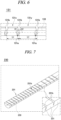
- the joint units 131 may be driven to deform the electrode guide 130 into the wound state in order to bring the electrode unit 122 into close contact with the outer surface of the tube in the body and efficiently transfer energy.
- Such a joint driving mechanism makes it possible to control an operation timing and the shape of the electrode guide 130 directly and improve the reliability of repetitive operation, as compared to a conventional shape memory material mechanism. Therefore, it is possible to perform a customized and detailed surgical procedure using the electrode apparatus 100 of the present disclosure.
- the electrode guide 130 is accommodated together with the electrode unit 120 inside the shaft 111 and may protrude from one end in a forward direction F while being deformed into the wound state at the time of surgical procedure.
- the plurality of joint units 131 may move toward one direction and thus may overall enclose the tube V in the wound state.
- the electrode guide 130 is spaced apart from an outer circumferential surface of the tube and the electrode unit 120 located inside the wound electrode guide 130 may be in close contact with the outer circumferential surface of the tube V.
- the electrode guide 130 may further include a tip joint 132 and a wire 133.
- the tip joint 132 may be connected to the shaft 111 by the plurality of joint units 131 and coupled to the electrode unit 120. As illustrated in FIG. 3C , the tip joint 132 may be located close to the tube V in the body in the wound state and may have a shape that gradually decreases in width or thickness toward the end in order to suppress interference with the electrode unit 120 or maximize the surface enclosing the tube in the body.
- the end of the electrode unit 120 may be fastened and fixed to the tip joint 132.
- the wire 133 may be formed to sequentially penetrate the plurality of joint units 131.
- each joint unit 131 may have a through-hole 131c in a longitudinal direction to allow penetration of the wire 133.
- the end of the wire 133 sequentially penetrating the through-holes 131c may be coupled and fixed to the tip joint 132, and the wire 133 can slide with respect to each joint unit 131 in the through-hole 131c in the longitudinal direction. Therefore, the wire 133 can guide the plurality of joint units 131 and the tip joint 132 to be in the wound state and support the tip joint 132 and the plurality of joint units 131 in the wound state.
- each join unit 131 may include hinge units 131a and winding support units 131b.
- the hinge units 131a are configured for rotatable connection to adjacent joints and may be formed on one or both sides of the joint unit 131 in the longitudinal direction in which the joint units 131 are connected parallel to each other.
- the hinge unit 131a may have a rotation axis in a direction intersecting the longitudinal direction so as to be connected to the hinge unit 131a of the adjacent joint unit 131.
- a hinge pin (not illustrated) may be inserted into and fastened to each hinge unit 131a in the direction of the rotation axis.
- the winding support units 131b are configured to maintain the wound state and may be formed on one or both sides of the joint unit 131 in the longitudinal direction to support the adjacent joint unit 131. As illustrated in FIG. 5 , the winding support unit 131b may be located adjacent to the hinge unit 131a in an inward direction of the electrode guide 130 (in a direction of winding the joint unit 131). For example, the winding support unit 131b may be formed as a surface having a predetermined angle and area and supported by the adjacent winding support unit 131b in surface contact with each other in the wound state, and, thus, a wound shape of the electrode guide 130 can be maintained.
- the winding support units 131b may provide a force of supporting the joint units 131 to each other in a direction of suppressing winding of the electrode guide 130. That is, since the wire 133 and the winding support units 131b form a balanced force in opposite directions, the electrode guide 130 can be fixed in the wound state.
- the through-hole 131c may be formed at a location spaced apart from a rotation center of the hinge unit 131a in an inward direction (in an upward direction in FIG. 6 ).
- the wire 133 of which the end is fixed to the tip joint 132 is pulled relatively backwards (toward a right direction in FIG. 6 )
- the plurality of joint units 131 may be bent overall in an inward direction.
- the locations of the plurality of joint units 131 may be fixed and the plurality of joint units 131 may be in the wound state.
- the wire 133 may provide a force (tensile force) of supporting the winding support units 131b to each other.
- the electrode guide 130 of the electrode apparatus 100 can maintain its location during a surgical procedure.
- the electrode guide 130 may include a first joint group 131x and a second joint group 131y. That is, the plurality of joint units 131 may be divided into the first joint group 131x and the second joint group 131y having different shapes.
- the first joint group 131x may include joint units 131 each having a first length L1 in the longitudinal direction
- the second joint group 131y may include joint units 131 each having a second length L2 greater than the first length L1.
- each of the first joint group 131x and the second joint group 131y may include, for example, six joint units 131 each having the same length.
- the first joint group 131x may form a first radius of curvature and the second joint group 131y may form a second radius of curvature greater than the first radius of curvature in the wound state.
- the joint units (the first joint group 131x) having a relatively small length may form a smaller radius of curvature and the joint units (the second joint group 131y) having a relatively great length may form a greater radius of curvature.
- first joint group 131x forming the first radius of curvature may be located close to the tip joint 132, and the second joint group 131y forming the second radius of curvature may be located close to the shaft 111.
- a path along which the tip joint 132 enters a space between the tube in the body and the shaft 111 may be formed as shown in FIG. 3C .
- the electrode guide 130 including the joint units 131 may have an overall spiral shape.
- the shape of the electrode guide 130 in the wound state can be easily and precisely set by designing the lengths of the plurality of joint units 131. Also, it is possible to secure excellent repeatability in the shape in the wound state. Further, the electrode guide 130 can be located to fully enclose the tube in the body in the wound state by varying the radius of curvature. Therefore, it is possible to generally denervate or modulate the nerves around the tube in a one-time surgical procedure and thus possible to increase the treatment effect.
- each joint unit 131 may be disposed in the longitudinal direction to intersect the adjacent joint unit 131 at a tilt angle of, for example, 30°.
- the respective surfaces of the winding support units 131b of the joint units 131 may have tilt angles ⁇ 1 and ⁇ 2 of, for example, 75° with respect to the longitudinal direction.
- the joint units 131 having the same length may have a plurality of radiuses of curvature in the wound state.
- a tilt angle between the adjacent joint units 131 in the wound state may be determined by tilt angles of the surfaces of the winding support units 131b with respect to the longitudinal direction of the joint units 131 when the joint units 131 are designed.
- a first joint group may include joint units in which surfaces of winding support units have a first angle with respect to the longitudinal direction
- a second joint group may include joint units in which surfaces of winding support units have a second angle greater than the first angle.
- the second joint group having the second angle may be disposed to have a second radius of curvature greater than the first radius of curvature.
- joint units 131 include two joint groups
- FIG. 7 is a perspective view of an electrode guide 230 according to another embodiment of the present disclosure.
- joint units 231 of the electrode guide 230 of the present disclosure are formed as one body will be described.
- the joint units 231 of the electrode guide 230 may be made of a material such as elastically deformable polymer, and a plurality of joint units 231 may be formed as one body, for example, a living hinge structure.
- each joint unit 231 may be formed as one body with another joint unit 231 adjacent to each other in the longitudinal direction, and a winding support groove 231b may be formed between the adjacent joint units 231. At least a part of a space in the winding support groove 231b may be reduced or closed in the wound state.
- the winding support groove 231b may be formed to be recessed in a wedge shape in the electrode guide 230's inner surface (a surface facing the electrode unit 120). In the wound state, side surfaces of the wedge-shaped winding support grooves 231b may be in contact with each other and may be supported by each other.
- the electrode guide 230 may further include a wire 233.
- the wire 233 may be formed to sequentially penetrate the plurality of joint units 231.
- a length of the wire 233 drawn out from the shaft 111 is smaller than that of the electrode guide 230, and, thus, the wire 233 can guide the electrode guide 230 to be deformed into a shape enclosing the tube and provide a force of closing and supporting at least part of the winding support grooves 231b.
- the electrode guide 230 can be manufactured as one body while implementing a reliable operation of the joint units. Since it is not necessary to assemble separately manufactured joint elements, the electrode guide 230 can be manufactured through a simple process and produced in a small size, which results in a reduction in manufacturing cost.
Landscapes
- Health & Medical Sciences (AREA)
- Life Sciences & Earth Sciences (AREA)
- Engineering & Computer Science (AREA)
- General Health & Medical Sciences (AREA)
- Animal Behavior & Ethology (AREA)
- Biomedical Technology (AREA)
- Nuclear Medicine, Radiotherapy & Molecular Imaging (AREA)
- Veterinary Medicine (AREA)
- Public Health (AREA)
- Heart & Thoracic Surgery (AREA)
- Surgery (AREA)
- Radiology & Medical Imaging (AREA)
- Neurosurgery (AREA)
- Neurology (AREA)
- Cardiology (AREA)
- Molecular Biology (AREA)
- Physics & Mathematics (AREA)
- Plasma & Fusion (AREA)
- Otolaryngology (AREA)
- Medical Informatics (AREA)
- Orthopedic Medicine & Surgery (AREA)
- Biophysics (AREA)
- Physiology (AREA)
- Electrotherapy Devices (AREA)
- Surgical Instruments (AREA)
- Orthopedics, Nursing, And Contraception (AREA)
Claims (12)
- Elektrodenvorrichtung zur Denervierung oder Modulation von Nerven im Körper, umfassend:einen Hauptkörper mit einem Schaft;eine Elektrodeneinheit, die ausgebildet ist, um aus einem Ende des Schafts herausgezogen zu werden, und konfiguriert ist, um mindestens einen Teil von Nerven an einer Röhre im Körper zu denervieren oder zu modulieren;
undeine Elektrodenführung, die mit der Elektrodeneinheit gekoppelt und in einen gewickelten Zustand verformt ist, um die Elektrodeneinheit mit der Röhre im Körper in Kontakt zu bringen;wobei die Elektrodenführung eine Vielzahl von Gelenkeinheiten umfasst, die angeordnet sind, um den Umfang der Röhre zu umschließen, wobei die Elektrodeneinheit im gewickelten Zustand dazwischen angeordnet ist. - Elektrodenvorrichtung nach Anspruch 1,
wobei jede Gelenkeinheit umfasst:eine Scharniereinheit, die auf einer oder beiden Seiten der Gelenkeinheit in einer Längsrichtung ausgebildet ist, um mit einer benachbarten Gelenkeinheit verbunden zu werden; undeine Wickelstützeinheit, die auf einer oder beiden Seiten der Gelenkeinheit in der Längsrichtung ausgebildet ist, um die benachbarte Gelenkeinheit im gewickelten Zustand zu stützen. - Elektrodenvorrichtung nach Anspruch 1,
wobei die Elektrodenführung im gewickelten Zustand umfasst:eine erste Gelenkgruppe mit einer Vielzahl von Gelenkeinheiten, die jeweils eine erste Länge in einer Längsrichtung aufweisen, um mit einer benachbarten Gelenkeinheit verbunden zu werden, und angeordnet sind, um einen ersten Krümmungsradius zu bilden; undeine zweite Gelenkgruppe mit einer Vielzahl von Gelenkeinheiten, die jeweils eine zweite Länge aufweisen, die größer als die Länge jeder Gelenkeinheit der ersten Gelenkgruppe in der Längsrichtung ist, und angeordnet sind, um einen zweiten Krümmungsradius zu bilden, der größer als der erste Krümmungsradius ist. - Elektrodenvorrichtung nach Anspruch 2,
wobei die Gelenkeinheiten im gewickelten Zustand umfassen:eine erste Gelenkgruppe mit einer Vielzahl von Gelenkeinheiten, in denen Oberflächen der Wickelstützeinheiten einen ersten Winkel in Bezug auf die Längsrichtung aufweisen und die angeordnet ist, um einen ersten Krümmungsradius zu bilden; undeine zweite Gelenkgruppe mit einer Vielzahl von Gelenkeinheiten, in denen Oberflächen der Wickelstützeinheiten einen zweiten Winkel aufweisen, der größer als der erste Winkel in Bezug auf die Längsrichtung ist, und die angeordnet ist, um einen zweiten Krümmungsradius zu bilden, der größer als der erste Krümmungsradius ist. - Elektrodenvorrichtung nach Anspruch 1,
wobei die Elektrodenführung ferner ein Spitzengelenk umfasst, das mit der Elektrodeneinheit gekoppelt und durch die Vielzahl von Gelenkeinheiten mit dem Schaft verbunden ist. - Elektrodenvorrichtung nach Anspruch 1,
wobei die Elektrodenführung ferner einen Draht umfasst, der ausgebildet ist, um nacheinander die Vielzahl von Gelenkeinheiten zu durchdringen, und konfiguriert ist, um die Vielzahl von Gelenkeinheiten zu führen, damit sie sich im gewickelten Zustand befinden. - Elektrodenvorrichtung nach Anspruch 5,
wobei die Elektrodenführung ferner einen Draht umfasst, der ausgebildet ist, um nacheinander die Vielzahl von Gelenkeinheiten zu durchdringen, und mit dem Spitzengelenk gekoppelt und konfiguriert ist, um die Position des Spitzengelenks im gewickelten Zustand zu führen. - Elektrodenvorrichtung nach Anspruch 2,
wobei jede Gelenkeinheit ferner umfasst:ein Durchgangsloch, das in der Längsrichtung an einer Position ausgebildet ist, die von einem Drehzentrum der Scharniereinheit beabstandet ist, unddie Elektrodenführung ferner einen Draht umfasst, der in das Durchgangsloch eingeführt und konfiguriert ist, um eine Kraft zum Stützen der Wickelstützeinheiten aneinander zwischen benachbarten Gelenkeinheiten bereitzustellen. - Elektrodenvorrichtung nach Anspruch 5,
wobei im gewickelten Zustand ein Krümmungsradius, der durch eine Vielzahl von Gelenkeinheiten gebildet wird, die sich nahe dem Spitzengelenk befinden, kleiner ist als ein Krümmungsradius, der durch eine Vielzahl von Gelenkeinheiten gebildet wird, die sich nahe dem Schaft befinden. - Elektrodenvorrichtung nach Anspruch 1,wobei die Vielzahl von Gelenkeinheiten aus einem elastisch verformbaren Material besteht und als ein Körper ausgebildet ist, undeine Wickelstütznut, von der mindestens ein Teil eines Raums verformt ist, um im gewickelten Zustand geschlossen zu werden, zwischen benachbarten Gelenkeinheiten der Elektrodenführung ausgebildet ist.
- Elektrodenvorrichtung nach Anspruch 10,
wobei die Wickelstütznut in einer Keilform in der Oberfläche der Elektrodenführung, die der Elektrodeneinheit zugewandt ist, ausgenommen ist. - Elektrodenvorrichtung nach Anspruch 10,
wobei die Elektrodenführung ferner einen Draht umfasst, der ausgebildet ist, um nacheinander die Vielzahl von Gelenkeinheiten zu durchdringen, und eine Kraft zum Schließen und Stützen mindestens eines Teils der Wickelstütznuten im gewickelten Zustand bereitstellt.
Applications Claiming Priority (2)
| Application Number | Priority Date | Filing Date | Title |
|---|---|---|---|
| KR1020200126817A KR102244131B1 (ko) | 2020-09-29 | 2020-09-29 | 체내의 신경을 차단 또는 조절하기 위한 전극 장치 |
| PCT/KR2020/013772 WO2022071621A1 (ko) | 2020-09-29 | 2020-10-08 | 체내의 신경을 차단 또는 조절하기 위한 전극 장치 |
Publications (3)
| Publication Number | Publication Date |
|---|---|
| EP4115829A1 EP4115829A1 (de) | 2023-01-11 |
| EP4115829A4 EP4115829A4 (de) | 2024-03-20 |
| EP4115829B1 true EP4115829B1 (de) | 2025-03-26 |
Family
ID=75738060
Family Applications (1)
| Application Number | Title | Priority Date | Filing Date |
|---|---|---|---|
| EP20956386.5A Active EP4115829B1 (de) | 2020-09-29 | 2020-10-08 | Elektrodenvorrichtung zur blockierung oder kontrolle von nerven im körper |
Country Status (9)
| Country | Link |
|---|---|
| US (1) | US20230157747A1 (de) |
| EP (1) | EP4115829B1 (de) |
| JP (1) | JP7465585B2 (de) |
| KR (2) | KR102244131B1 (de) |
| CN (1) | CN115461006B (de) |
| AU (1) | AU2020470159B2 (de) |
| BR (1) | BR112022021948A2 (de) |
| ES (1) | ES3020083T3 (de) |
| WO (1) | WO2022071621A1 (de) |
Families Citing this family (12)
| Publication number | Priority date | Publication date | Assignee | Title |
|---|---|---|---|---|
| KR102296026B1 (ko) * | 2020-12-03 | 2021-09-02 | 주식회사 딥큐어 | 전극 장치 |
| KR102296027B1 (ko) * | 2021-02-10 | 2021-09-01 | 주식회사 딥큐어 | 체내의 신경을 차단 또는 조절하기 위한 전극 장치 |
| CN116940398A (zh) * | 2021-04-01 | 2023-10-24 | 迪普库雷公司 | 一种用于去神经或调整体内神经的电极装置 |
| KR102347531B1 (ko) * | 2021-06-08 | 2022-01-07 | 주식회사 딥큐어 | 전극 유닛 및 이를 포함하는 전극 장치 |
| KR102354491B1 (ko) * | 2021-07-13 | 2022-01-24 | 주식회사 딥큐어 | 체내의 신경을 차단 또는 조절하기 위한 전극 장치 |
| KR102305703B1 (ko) * | 2021-07-13 | 2021-09-29 | 주식회사 딥큐어 | 체내의 신경을 차단 또는 조절하기 위한 전극 장치 |
| KR102388034B1 (ko) * | 2021-07-29 | 2022-04-20 | 주식회사 딥큐어 | 체내의 신경을 차단 또는 조절하기 위한 전극 장치 |
| CA3229340A1 (en) * | 2021-08-18 | 2023-02-23 | Du Jin Bach | Electrode apparatus for nerve denervation or modulation in vivo |
| US20250331916A1 (en) * | 2021-08-18 | 2025-10-30 | Deepqure Inc. | Electrode apparatus for nerve denervation or modulation in vivo |
| EP4368130A4 (de) * | 2021-08-25 | 2025-04-09 | Deepqure Inc. | Elektrodenvorrichtung zur blockierung oder kontrolle von nerven im körper |
| KR102818849B1 (ko) * | 2022-10-25 | 2025-06-16 | 주식회사 딥큐어 | 체내의 신경을 차단 또는 조절하기 위한 전극 장치 |
| KR102890587B1 (ko) * | 2023-04-14 | 2025-11-26 | 주식회사 딥큐어 | 체내의 신경을 차단 또는 조절하기 위한 전극 장치 및 이를 이용한 수술 로봇 |
Family Cites Families (17)
| Publication number | Priority date | Publication date | Assignee | Title |
|---|---|---|---|---|
| US6719755B2 (en) * | 1996-10-22 | 2004-04-13 | Epicor Medical, Inc. | Methods and devices for ablation |
| US7527590B2 (en) | 2002-03-19 | 2009-05-05 | Olympus Corporation | Anastomosis system |
| US20040111139A1 (en) * | 2002-12-10 | 2004-06-10 | Mccreery Douglas B. | Apparatus and methods for differential stimulation of nerve fibers |
| US20040199052A1 (en) | 2003-04-01 | 2004-10-07 | Scimed Life Systems, Inc. | Endoscopic imaging system |
| US9554691B2 (en) | 2004-04-21 | 2017-01-31 | Acclarent, Inc. | Endoscopic methods and devices for transnasal procedures |
| US8758349B2 (en) * | 2008-10-13 | 2014-06-24 | Dfine, Inc. | Systems for treating a vertebral body |
| WO2010039894A1 (en) * | 2008-09-30 | 2010-04-08 | Dfine, Inc. | System for use in treatment of vertebral fractures |
| ES2757726T3 (es) * | 2010-04-26 | 2020-04-30 | Medtronic Ardian Luxembourg | Aparatos y sistemas de catéter para la neuromodulación renal |
| CA2929660A1 (en) * | 2013-11-19 | 2015-05-28 | Ethicon, Inc. | Thoracoscopic methods for treatment of bronchial disease |
| KR101761135B1 (ko) * | 2014-07-11 | 2017-07-25 | (주)선메딕스 | 전기수술용 기구 |
| US11134978B2 (en) | 2016-01-15 | 2021-10-05 | Cilag Gmbh International | Modular battery powered handheld surgical instrument with self-diagnosing control switches for reusable handle assembly |
| US20180042664A1 (en) * | 2016-08-10 | 2018-02-15 | Pacestter, Inc. | Steerable radiofrequency denervation probe for genicular nerve denervation and methods of use |
| US20190133681A1 (en) * | 2016-09-07 | 2019-05-09 | Chang Wook Jeong | Systems and methods for perivascular nerve denervation |
| US10639462B2 (en) * | 2016-10-18 | 2020-05-05 | Acclarent, Inc. | Dilation system |
| TWI795414B (zh) | 2017-06-29 | 2023-03-11 | 美商美國德州系統大學評議委員會 | 手術設備及其手術工具 |
| AU2018385603B2 (en) * | 2017-12-13 | 2024-05-02 | Neuros Medical, Inc. | Nerve cuff deployment devices |
| KR102133275B1 (ko) * | 2018-02-26 | 2020-07-13 | 한국기계연구원 | 수술용 가이드 어셈블리 및 이를 이용한 수술용 가이드 장치 |
-
2020
- 2020-09-29 KR KR1020200126817A patent/KR102244131B1/ko active Active
- 2020-10-08 CN CN202080100271.8A patent/CN115461006B/zh active Active
- 2020-10-08 BR BR112022021948A patent/BR112022021948A2/pt unknown
- 2020-10-08 EP EP20956386.5A patent/EP4115829B1/de active Active
- 2020-10-08 JP JP2022568994A patent/JP7465585B2/ja active Active
- 2020-10-08 US US17/921,690 patent/US20230157747A1/en active Pending
- 2020-10-08 ES ES20956386T patent/ES3020083T3/es active Active
- 2020-10-08 AU AU2020470159A patent/AU2020470159B2/en active Active
- 2020-10-08 WO PCT/KR2020/013772 patent/WO2022071621A1/ko not_active Ceased
-
2021
- 2021-04-19 KR KR1020210050248A patent/KR102462417B1/ko active Active
Also Published As
| Publication number | Publication date |
|---|---|
| WO2022071621A1 (ko) | 2022-04-07 |
| EP4115829A4 (de) | 2024-03-20 |
| ES3020083T3 (en) | 2025-05-21 |
| BR112022021948A2 (pt) | 2023-04-11 |
| CA3176988A1 (en) | 2022-04-07 |
| US20230157747A1 (en) | 2023-05-25 |
| KR102244131B1 (ko) | 2021-04-23 |
| JP2023525350A (ja) | 2023-06-15 |
| KR20220043831A (ko) | 2022-04-05 |
| EP4115829A1 (de) | 2023-01-11 |
| CN115461006A (zh) | 2022-12-09 |
| AU2020470159B2 (en) | 2024-04-11 |
| CN115461006B (zh) | 2025-07-18 |
| AU2020470159A1 (en) | 2022-11-03 |
| KR102462417B1 (ko) | 2022-11-04 |
| JP7465585B2 (ja) | 2024-04-11 |
Similar Documents
| Publication | Publication Date | Title |
|---|---|---|
| AU2020470159B2 (en) | Electrode apparatus for blocking or controlling nerves in body | |
| AU2020479941B2 (en) | Electrode device | |
| AU2021456078B2 (en) | Electrode device for blocking or controlling nerves in body | |
| AU2021438406B2 (en) | Electrode device for blocking or controlling nerves in body | |
| AU2021449806B2 (en) | Electrode unit and electrode device including same | |
| AU2021426776B2 (en) | Electrode apparatus for blocking or controlling nerves in body | |
| AU2021456077B2 (en) | Electrode device for blocking or controlling nerves in body | |
| AU2021461291B2 (en) | Electrode apparatus for nerve denervation or modulation in vivo | |
| CA3176988C (en) | Electrode apparatus for nerve denervation or modulation in body | |
| US20240366292A1 (en) | Electrode device for blocking or controlling nerves in body |
Legal Events
| Date | Code | Title | Description |
|---|---|---|---|
| STAA | Information on the status of an ep patent application or granted ep patent |
Free format text: STATUS: THE INTERNATIONAL PUBLICATION HAS BEEN MADE |
|
| PUAI | Public reference made under article 153(3) epc to a published international application that has entered the european phase |
Free format text: ORIGINAL CODE: 0009012 |
|
| STAA | Information on the status of an ep patent application or granted ep patent |
Free format text: STATUS: REQUEST FOR EXAMINATION WAS MADE |
|
| 17P | Request for examination filed |
Effective date: 20221005 |
|
| AK | Designated contracting states |
Kind code of ref document: A1 Designated state(s): AL AT BE BG CH CY CZ DE DK EE ES FI FR GB GR HR HU IE IS IT LI LT LU LV MC MK MT NL NO PL PT RO RS SE SI SK SM TR |
|
| DAV | Request for validation of the european patent (deleted) | ||
| DAX | Request for extension of the european patent (deleted) | ||
| A4 | Supplementary search report drawn up and despatched |
Effective date: 20240216 |
|
| RIC1 | Information provided on ipc code assigned before grant |
Ipc: A61B 18/00 20060101ALI20240212BHEP Ipc: A61N 1/05 20060101ALI20240212BHEP Ipc: A61N 1/36 20060101ALI20240212BHEP Ipc: A61B 18/14 20060101AFI20240212BHEP |
|
| GRAP | Despatch of communication of intention to grant a patent |
Free format text: ORIGINAL CODE: EPIDOSNIGR1 |
|
| STAA | Information on the status of an ep patent application or granted ep patent |
Free format text: STATUS: GRANT OF PATENT IS INTENDED |
|
| INTG | Intention to grant announced |
Effective date: 20241031 |
|
| GRAS | Grant fee paid |
Free format text: ORIGINAL CODE: EPIDOSNIGR3 |
|
| GRAA | (expected) grant |
Free format text: ORIGINAL CODE: 0009210 |
|
| STAA | Information on the status of an ep patent application or granted ep patent |
Free format text: STATUS: THE PATENT HAS BEEN GRANTED |
|
| AK | Designated contracting states |
Kind code of ref document: B1 Designated state(s): AL AT BE BG CH CY CZ DE DK EE ES FI FR GB GR HR HU IE IS IT LI LT LU LV MC MK MT NL NO PL PT RO RS SE SI SK SM TR |
|
| REG | Reference to a national code |
Ref country code: GB Ref legal event code: FG4D |
|
| REG | Reference to a national code |
Ref country code: CH Ref legal event code: EP |
|
| REG | Reference to a national code |
Ref country code: DE Ref legal event code: R096 Ref document number: 602020048564 Country of ref document: DE |
|
| REG | Reference to a national code |
Ref country code: IE Ref legal event code: FG4D |
|
| REG | Reference to a national code |
Ref country code: ES Ref legal event code: FG2A Ref document number: 3020083 Country of ref document: ES Kind code of ref document: T3 Effective date: 20250521 |
|
| PG25 | Lapsed in a contracting state [announced via postgrant information from national office to epo] |
Ref country code: RS Free format text: LAPSE BECAUSE OF FAILURE TO SUBMIT A TRANSLATION OF THE DESCRIPTION OR TO PAY THE FEE WITHIN THE PRESCRIBED TIME-LIMIT Effective date: 20250626 |
|
| PG25 | Lapsed in a contracting state [announced via postgrant information from national office to epo] |
Ref country code: FI Free format text: LAPSE BECAUSE OF FAILURE TO SUBMIT A TRANSLATION OF THE DESCRIPTION OR TO PAY THE FEE WITHIN THE PRESCRIBED TIME-LIMIT Effective date: 20250326 |
|
| REG | Reference to a national code |
Ref country code: LT Ref legal event code: MG9D |
|
| PG25 | Lapsed in a contracting state [announced via postgrant information from national office to epo] |
Ref country code: NO Free format text: LAPSE BECAUSE OF FAILURE TO SUBMIT A TRANSLATION OF THE DESCRIPTION OR TO PAY THE FEE WITHIN THE PRESCRIBED TIME-LIMIT Effective date: 20250626 |
|
| PG25 | Lapsed in a contracting state [announced via postgrant information from national office to epo] |
Ref country code: HR Free format text: LAPSE BECAUSE OF FAILURE TO SUBMIT A TRANSLATION OF THE DESCRIPTION OR TO PAY THE FEE WITHIN THE PRESCRIBED TIME-LIMIT Effective date: 20250326 |
|
| PG25 | Lapsed in a contracting state [announced via postgrant information from national office to epo] |
Ref country code: LV Free format text: LAPSE BECAUSE OF FAILURE TO SUBMIT A TRANSLATION OF THE DESCRIPTION OR TO PAY THE FEE WITHIN THE PRESCRIBED TIME-LIMIT Effective date: 20250326 |
|
| PG25 | Lapsed in a contracting state [announced via postgrant information from national office to epo] |
Ref country code: GR Free format text: LAPSE BECAUSE OF FAILURE TO SUBMIT A TRANSLATION OF THE DESCRIPTION OR TO PAY THE FEE WITHIN THE PRESCRIBED TIME-LIMIT Effective date: 20250627 Ref country code: BG Free format text: LAPSE BECAUSE OF FAILURE TO SUBMIT A TRANSLATION OF THE DESCRIPTION OR TO PAY THE FEE WITHIN THE PRESCRIBED TIME-LIMIT Effective date: 20250326 |
|
| REG | Reference to a national code |
Ref country code: NL Ref legal event code: MP Effective date: 20250326 |
|
| PG25 | Lapsed in a contracting state [announced via postgrant information from national office to epo] |
Ref country code: NL Free format text: LAPSE BECAUSE OF FAILURE TO SUBMIT A TRANSLATION OF THE DESCRIPTION OR TO PAY THE FEE WITHIN THE PRESCRIBED TIME-LIMIT Effective date: 20250326 |
|
| PG25 | Lapsed in a contracting state [announced via postgrant information from national office to epo] |
Ref country code: SE Free format text: LAPSE BECAUSE OF FAILURE TO SUBMIT A TRANSLATION OF THE DESCRIPTION OR TO PAY THE FEE WITHIN THE PRESCRIBED TIME-LIMIT Effective date: 20250326 |
|
| REG | Reference to a national code |
Ref country code: AT Ref legal event code: MK05 Ref document number: 1778272 Country of ref document: AT Kind code of ref document: T Effective date: 20250326 |
|
| PG25 | Lapsed in a contracting state [announced via postgrant information from national office to epo] |
Ref country code: SM Free format text: LAPSE BECAUSE OF FAILURE TO SUBMIT A TRANSLATION OF THE DESCRIPTION OR TO PAY THE FEE WITHIN THE PRESCRIBED TIME-LIMIT Effective date: 20250326 |
|
| PG25 | Lapsed in a contracting state [announced via postgrant information from national office to epo] |
Ref country code: PT Free format text: LAPSE BECAUSE OF FAILURE TO SUBMIT A TRANSLATION OF THE DESCRIPTION OR TO PAY THE FEE WITHIN THE PRESCRIBED TIME-LIMIT Effective date: 20250728 |
|
| PG25 | Lapsed in a contracting state [announced via postgrant information from national office to epo] |
Ref country code: PL Free format text: LAPSE BECAUSE OF FAILURE TO SUBMIT A TRANSLATION OF THE DESCRIPTION OR TO PAY THE FEE WITHIN THE PRESCRIBED TIME-LIMIT Effective date: 20250326 |
|
| PG25 | Lapsed in a contracting state [announced via postgrant information from national office to epo] |
Ref country code: AT Free format text: LAPSE BECAUSE OF FAILURE TO SUBMIT A TRANSLATION OF THE DESCRIPTION OR TO PAY THE FEE WITHIN THE PRESCRIBED TIME-LIMIT Effective date: 20250326 |
|
| PG25 | Lapsed in a contracting state [announced via postgrant information from national office to epo] |
Ref country code: EE Free format text: LAPSE BECAUSE OF FAILURE TO SUBMIT A TRANSLATION OF THE DESCRIPTION OR TO PAY THE FEE WITHIN THE PRESCRIBED TIME-LIMIT Effective date: 20250326 |
|
| PG25 | Lapsed in a contracting state [announced via postgrant information from national office to epo] |
Ref country code: RO Free format text: LAPSE BECAUSE OF FAILURE TO SUBMIT A TRANSLATION OF THE DESCRIPTION OR TO PAY THE FEE WITHIN THE PRESCRIBED TIME-LIMIT Effective date: 20250326 |
|
| PG25 | Lapsed in a contracting state [announced via postgrant information from national office to epo] |
Ref country code: SK Free format text: LAPSE BECAUSE OF FAILURE TO SUBMIT A TRANSLATION OF THE DESCRIPTION OR TO PAY THE FEE WITHIN THE PRESCRIBED TIME-LIMIT Effective date: 20250326 |
|
| PG25 | Lapsed in a contracting state [announced via postgrant information from national office to epo] |
Ref country code: IS Free format text: LAPSE BECAUSE OF FAILURE TO SUBMIT A TRANSLATION OF THE DESCRIPTION OR TO PAY THE FEE WITHIN THE PRESCRIBED TIME-LIMIT Effective date: 20250726 |
|
| REG | Reference to a national code |
Ref country code: CH Ref legal event code: U11 Free format text: ST27 STATUS EVENT CODE: U-0-0-U10-U11 (AS PROVIDED BY THE NATIONAL OFFICE) Effective date: 20251101 |
|
| REG | Reference to a national code |
Ref country code: DE Ref legal event code: R097 Ref document number: 602020048564 Country of ref document: DE |
|
| PGFP | Annual fee paid to national office [announced via postgrant information from national office to epo] |
Ref country code: GB Payment date: 20251022 Year of fee payment: 6 |
|
| PG25 | Lapsed in a contracting state [announced via postgrant information from national office to epo] |
Ref country code: DK Free format text: LAPSE BECAUSE OF FAILURE TO SUBMIT A TRANSLATION OF THE DESCRIPTION OR TO PAY THE FEE WITHIN THE PRESCRIBED TIME-LIMIT Effective date: 20250326 |
|
| PGFP | Annual fee paid to national office [announced via postgrant information from national office to epo] |
Ref country code: IT Payment date: 20251024 Year of fee payment: 6 |
|
| PGFP | Annual fee paid to national office [announced via postgrant information from national office to epo] |
Ref country code: FR Payment date: 20251030 Year of fee payment: 6 |
|
| PGFP | Annual fee paid to national office [announced via postgrant information from national office to epo] |
Ref country code: CH Payment date: 20251101 Year of fee payment: 6 |
|
| PG25 | Lapsed in a contracting state [announced via postgrant information from national office to epo] |
Ref country code: CZ Free format text: LAPSE BECAUSE OF FAILURE TO SUBMIT A TRANSLATION OF THE DESCRIPTION OR TO PAY THE FEE WITHIN THE PRESCRIBED TIME-LIMIT Effective date: 20250326 |
|
| PGFP | Annual fee paid to national office [announced via postgrant information from national office to epo] |
Ref country code: ES Payment date: 20251216 Year of fee payment: 6 |
|
| PLBE | No opposition filed within time limit |
Free format text: ORIGINAL CODE: 0009261 |
|
| STAA | Information on the status of an ep patent application or granted ep patent |
Free format text: STATUS: NO OPPOSITION FILED WITHIN TIME LIMIT |
|
| REG | Reference to a national code |
Ref country code: CH Ref legal event code: L10 Free format text: ST27 STATUS EVENT CODE: U-0-0-L10-L00 (AS PROVIDED BY THE NATIONAL OFFICE) Effective date: 20260211 |
|
| 26N | No opposition filed |
Effective date: 20260105 |
|
| PGFP | Annual fee paid to national office [announced via postgrant information from national office to epo] |
Ref country code: DE Payment date: 20251229 Year of fee payment: 6 |