EP4115258B1 - Durchflussregler - Google Patents
Durchflussregler Download PDFInfo
- Publication number
- EP4115258B1 EP4115258B1 EP21715674.4A EP21715674A EP4115258B1 EP 4115258 B1 EP4115258 B1 EP 4115258B1 EP 21715674 A EP21715674 A EP 21715674A EP 4115258 B1 EP4115258 B1 EP 4115258B1
- Authority
- EP
- European Patent Office
- Prior art keywords
- notch
- flow regulator
- flow
- water
- piston member
- Prior art date
- Legal status (The legal status is an assumption and is not a legal conclusion. Google has not performed a legal analysis and makes no representation as to the accuracy of the status listed.)
- Active
Links
Images




Classifications
-
- F—MECHANICAL ENGINEERING; LIGHTING; HEATING; WEAPONS; BLASTING
- F16—ENGINEERING ELEMENTS AND UNITS; GENERAL MEASURES FOR PRODUCING AND MAINTAINING EFFECTIVE FUNCTIONING OF MACHINES OR INSTALLATIONS; THERMAL INSULATION IN GENERAL
- F16K—VALVES; TAPS; COCKS; ACTUATING-FLOATS; DEVICES FOR VENTING OR AERATING
- F16K31/00—Actuating devices; Operating means; Releasing devices
- F16K31/12—Actuating devices; Operating means; Releasing devices actuated by fluid
- F16K31/36—Actuating devices; Operating means; Releasing devices actuated by fluid in which fluid from the circuit is constantly supplied to the fluid motor
- F16K31/38—Actuating devices; Operating means; Releasing devices actuated by fluid in which fluid from the circuit is constantly supplied to the fluid motor in which the fluid works directly on both sides of the fluid motor, one side being connected by means of a restricted passage and the motor being actuated by operating a discharge from that side
- F16K31/383—Actuating devices; Operating means; Releasing devices actuated by fluid in which fluid from the circuit is constantly supplied to the fluid motor in which the fluid works directly on both sides of the fluid motor, one side being connected by means of a restricted passage and the motor being actuated by operating a discharge from that side the fluid acting on a piston
-
- G—PHYSICS
- G05—CONTROLLING; REGULATING
- G05D—SYSTEMS FOR CONTROLLING OR REGULATING NON-ELECTRIC VARIABLES
- G05D7/00—Control of flow
- G05D7/01—Control of flow without auxiliary power
-
- G—PHYSICS
- G05—CONTROLLING; REGULATING
- G05D—SYSTEMS FOR CONTROLLING OR REGULATING NON-ELECTRIC VARIABLES
- G05D7/00—Control of flow
- G05D7/01—Control of flow without auxiliary power
- G05D7/0126—Control of flow without auxiliary power the sensing element being a piston or plunger associated with one or more springs
- G05D7/0133—Control of flow without auxiliary power the sensing element being a piston or plunger associated with one or more springs within the flow-path
-
- G—PHYSICS
- G05—CONTROLLING; REGULATING
- G05D—SYSTEMS FOR CONTROLLING OR REGULATING NON-ELECTRIC VARIABLES
- G05D7/00—Control of flow
- G05D7/06—Control of flow characterised by the use of electric means
Definitions
- Embodiments of the invention relate to a flow regulator, in particular for use in irrigation application.
- Flow regulators are commonly used for regulating liquid flow within irrigation systems. Such flow regulators can vary from simple orifices to more complex hydraulic networks that can compensate for changes in pressure.
- US2986157 for example describes a pilot valve that can be used for opening and closing valves in response to pressure.
- the pilot valve includes relative small passageways through which hydraulic pressure can be used for controlling the control valve.
- US 2005/211305 A1 describes a flow control valve that includes a valve body having an inlet, an outlet, a flow passageway coupling the inlet to the outlet, and a cavity with first and second chambers.
- the valve further includes a hollow piston disposed in the first chamber and a seal separating the first and second chambers.
- the seal has a section within the piston that is exposed to the fluid in the first chamber.
- the section of the seal defines a first effective area.
- the valve also includes a biasing member configured to urge the piston, and a reference pressure passageway in fluid communication with the inlet and the second chamber.
- US 2006/021657 A1 describes an inline liquid flow control valve that includes an intake fitting member with a bottom portion having a bottom portion threaded section and a liquid flow section having apertures.
- the valve further includes an outlet fitting member with a top portion having a liquid outlet section with apertures.
- a top portion threaded section of the outlet fitting member engages a bottom portion threaded section of the intake fitting member with a compression member disposed therebetween.
- the compression member engaging a piston disposed internally within the intake fitting member.
- the apertures in the intake fitting member, apertures in the piston, an annular sleeve and the plurality of apertures in the outlet fitting member define a liquid flow chamber.
- a flow rate of liquid through the liquid flow chamber is inlinely adjustable and maintainable using an internally disposed compression member.
- Flow regulators used in irrigation systems that channel relatively dirty water should preferably include relative large passageways so that they will not clog easily and consequently function as designed for regulating flow.
- a flow regulator for regulating a flow rate of water within at least a section of a water system, for example an irrigation system
- the flow regulator comprising a base member and piston member that is movable relative to the base member, the piston member comprises at least one notch through which water can flow when passing through the flow regulator, wherein movement of the piston member towards and away from the base member is adapted to, respectively, decrease and increase an area of the notch through which water can flow.
- the piston member comprises an opening upstream to the notch through which water first passes.
- water flowing through the flow regulator cannot bypass the at least one notch and/or opening into the piston member.
- the at least one notch provides a passage therethrough that gradually decreases from a beginning where the notch is deeper to an end where the notch is shallower.
- Such gradual decrease may be defined as following a substantial helical route that spirals about at least a section of the piston member.
- the piston member comprises a generally cylindrical shape that is hollow along at least a portion of its axis thus forming a peripheral shroud, and the at least one notch is formed at a downstream side of the shroud.
- movement of the piston member towards and away from the base member is affected by water pressure existing upstream and downstream to an entry into the piston member.
- the relative large water passages provided through the flow regulator provide relative high reliability of operation with dirty water, thus substantially reducing likelihood of blocking of the regulator during use.
- the self-regulating movements provided in the flow regulator during operation permit substantially constant change of passage sizes through the regulator that assist in removal of debris/dirt that may get caught within water passages of the regulator.
- dirt caught within a notch of the flow regulator may be released from said position at the notch to flow downstream as downstream pressure rises and urges the piston member to move away from the base member.
- FIG. 1A illustrating a possible filtration setup 10 that may be located at an upstream side of an irrigation system.
- the filtration setup in this example includes a plurality of media filters 12.
- the filtering setup may be arranged in groups 14 (here three such groups) each including several media filters 12 (here five).
- Each group 14 within the filtration setup may include an incoming pipe 16, an outgoing pipe 18 and a flushing pipe 20.
- Each media filter 12 may be coupled at its upper side 5 via a three-way valve 22 to the incoming and flushing pipes 16, 20; and at its lower side 7 to the outgoing pipe 18.
- the three-way valve associated with the filter can be controlled to open a flow path for water arriving from the incoming pipe 16 to flow into the filter via its upper side 5 (while blocking a route to the flushing pipe 20).
- the water flowing downwards through the media within the filter can then be emitted out of the filter at its lower side 7 into the outgoing pipe 18 and from there possibly onwards downstream to irrigate a field (or the like).
- the three-way valve associated with the filter can be controlled to open a flow path between the filter's upper side 5 and the flushing pipe 20 (while blocking a route to the incoming pipe 16).
- Pressurized water present within the outgoing pipe 18 can then flow upwards into the filter via its lower side 7 to flush dirt out of the media within the filter, and then flow out through the upper side 5 of the filter to flushing pipe 20 and from there onwards to a reservoir, the ambient environment or any other means suitable for receiving such relative dirty water.
- Pressurized water within the outgoing pipe 18 suitable for powering a flushing cycle of a media filter may be obtained by controlling the three-way valves of all but one of the media filters to perform a filtering cycle - while a remaining one of the filters can be controlled via its three-way valve to perform a flushing cycle.
- the majority of the water being filtered by the media filters can used for their intended purpose (e.g. irrigation) while a small portion can be harnessed for flushing one of the media filters.
- an embodiment of a flow regulator 24 may be fitted to a downstream side of each flushing pipe 20.
- the flow regulator 24 may be aimed at regulating the flow rate of water passing through the flushing pipe during a flushing cycle of a filter, to a suitable flow rate range that is substantially optimized for flushing dirt out of the media within the filter, while substantially avoiding or limiting loss of media particles from being flushed out of the filter together with the water passing therethrough.
- system 100 is a flood irrigation system suitable for delivering water to a field via a pipe 101 so that the water simply flows over the ground through crops in the field.
- FIGs. 2A and 2B illustrating an embodiment of a flow regulator 24 of the present invention.
- the flow regulator has an upstream side 241 through which water enters the regulator and a downstream side 242 through which water exits the regulator.
- the flow regulator has an outer housing 26 formed in this example of upstream and downstream portions 261, 262.
- the outer housing encloses the following main elements: a piston member 28, an orifice member 30 and a base member 32.
- the orifice member 30 includes a generally ring shaped substantially flat orifice face 301 and a through-going aperture 302 that passes through face 301.
- the orifice member 30 in addition includes coupling members 303, here at its lower downstream side, for coupling it to the piston member.
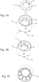
- the piston member 28 has a generally cylindrical shape, a flange 281 at a generally upstream side thereof that defines an opening 282, and a peripheral shroud 283 that includes a jagged lower side 282 formed of angular notches 2821.
- Each angular notch 2821 in this example gradually descends (here in a generally linear fashion) in a peripheral direction from a beginning 1 where the notch is deeper to an end 2 where the notch is shallower.
- Adjacent notches 2821 in this example are peripherally spaced apart by partitions 99.
- the orifice member 30 can be fitted, possibly snap fitted via its coupling members 303, onto the piston member 28 (see Fig. 3B ) to align its aperture 302 with opening 282.
- a relative general purpose flow regulator may be performed so that it can regulate flow passing therethrough to a desired flow rate range suitable e.g. for flushing a certain media filter without substantially loosing media particles during such flushing action.
- the piston member 28 may include a plurality of bore members 283 at a lower downstream side of its flange 281.
- Base member 32 includes a generally cylindrical core 321 and a plurality of upwardly projecting rests 322 that rise above an upper side of the core.
- Each rest 322 includes at its upper side a rod 323 of smaller diameter that projects further upwards.
- the core at its periphery 324 follows a generally cone shape that diverges slightly downwards towards a peripheral rim 325, and the core is formed at its periphery 324 with a plurality of passages 326 that provide each a route that communicates between periphery 324 and a lower side of the base member.
- Figs. 5A and 5B providing cross sectional views of the flow regulator during different regulating states.
- the piston member 28 can be placed above the base member 32 with each rod 323 of the base member 32 interacting and being located within a respective bore member 283 of the piston.
- biasing members 40 here in form of compression springs, may be placed upon at least some of the rods 323 and their respective bore and rest members 283, 322 . Such biasing members 40 may thus be held in between a lower side of the piston's flange 281 and the base member's core 321.
- Piston member 28 may be placed above base member 32 with its shroud 283 generally adjacent its jagged lower side - generally surrounding periphery 324 of the base member's core.
- the piston and base members in the assembled state form a chamber 3 therebetween that can be exited at its downstream side via the notches 2821 and at its upstream side via aperture 302.
- the pressure of water at the upstream side 241 of the flow regulator bears against orifice face 301 of the orifice member, to apply a force Fu that acts to bias piston member 28 towards base member 32.
- the piston member may moves towards the base member and by that gradually/proportionally decrease the area of the notches through which water can flow downstream (see Fig. 5B ).
- the flow rate of water passing through the flow regulator decreases proportionally while building pressure at a downstream side of aperture 302 (i.e. at chamber 3 located in between aperture 302 and the notches 2821) that forms a combined force Fc (applied by the pressure and springs) that bears against the piston member in an upstream direction.
- the piston member may move back upstream in a direction away from the base member and by that the area of the notches through which water can pass increases, thereby increasing the flow rate through the flow regulator.
- the movement of the piston member may thus oscillate upstream and downstream due to pressure fluctuations upstream and downstream of the piston and by that regulate the flow rate of water passing through the flow regulator within a given flow rate range defined by dimensions of the flow regulator and the diameter 302 of the detachable orifice member.
- a given flow regulator 24 may be adjusted for different working conditions by suitably choosing its biasing means and in particular the aperture size of its detachable orifice member.
- a certain sized flow regulator used in a system generally exhibiting a first flow rate may be equipped with biasing means having a first spring constant and an aperture 302 of a first diameter.
- a similar flow regulator however when used in different working conditions may be equipped with different type springs and a different aperture diameter.
Landscapes
- Engineering & Computer Science (AREA)
- Physics & Mathematics (AREA)
- General Physics & Mathematics (AREA)
- Automation & Control Theory (AREA)
- General Engineering & Computer Science (AREA)
- Mechanical Engineering (AREA)
- Flow Control (AREA)
- Fuel-Injection Apparatus (AREA)
- Compression-Type Refrigeration Machines With Reversible Cycles (AREA)
- Safety Valves (AREA)
Claims (17)
- Durchflussregler (24) zum Regulieren einer Wasserdurchflussmenge in zumindest einem Abschnitt eines Bewässerungssystems, wobei der Durchflussregler (24) aufweist:ein Basiselement (32) und ein Kolbenelement (28), das relativ zu dem Basiselement (32) beweglich ist, wobei das Kolbenelement (28) zumindest eine Kerbe (2821) aufweist, durch die Wasser fließen kann, wenn es durch den Durchflussregler (24) hindurchströmt, wobeidie Bewegung des Kolbenelements (28) auf das Basiselement (32) zu und von diesem weg als Reaktion auf den Wasserdruck, der stromaufwärts und stromabwärts von einem Einlass in das Kolbenelement (28) herrscht, dazu ausgelegt ist, einen Bereich der Kerbe (2821), durch die Wasser fließen kann, zu verringern bzw. zu vergrößern, und wobeidas Kolbenelement (28) stromaufwärts des Basiselements (32) liegt, undder Durchflussregler (24) ein mit dem Kolbenelement (28) gekoppeltes Öffnungselement (30) aufweist, durch das das gesamte durch den Durchflussregler fließende Wasser hindurchströmen muss.
- Durchflussregler nach Anspruch 1, wobei das durch den Durchflussregler (24) fließende Wasser die zumindest eine Kerbe (2821) nicht umgehen kann.
- Durchflussregler nach einem der vorhergehenden Ansprüche, wobei die zumindest eine Kerbe (2821) einen Durchgang bereitstellt, der sich von einem Anfangsabschnitt, an dem die Kerbe (2821) tiefer ausgeführt ist, bis zu einem Endabschnitt, an dem die Kerbe flacher ausgeführt ist, allmählich verringert.
- Durchflussregler nach Anspruch 3, wobei eine Verringerung in dem Bereich der Kerbe (2821), durch die Wasser fließen kann, das Sperren eines dem Endabschnitt der Kerbe benachbarten Kerbenbereichs aufweist.
- Durchflussregler nach einem der vorhergehenden Ansprüche, aufweisend eine Vorspanneinrichtung (40), die dazu ausgelegt ist, das Kolbenelement (28) von dem Basiselement weg zu bewegen.
- Durchflussregler nach einem der vorhergehenden Ansprüche, wobei das Öffnungselement (30) lösbar mit dem Kolbenelement gekoppelt ist.
- Durchflussregler nach einem der vorhergehenden Ansprüche, wobei die Bewegung des Kolbenelements (28) auf das Basiselement (32) zu dazu ausgelegt ist, den stromabwärts gerichteten Druck zu erhöhen.
- Durchflussregler nach Anspruch 6, wobei der stromabwärts von einem Einlass in das Kolbenelement (28) herrschende und die Bewegung des Kolbens beeinflussende Wasserdruck im Wesentlichen ein Druck ist, der in einer zwischen dem Basis- und dem Kolbenelement (28) angeordneten Kammer (3) herrscht.
- Durchflussregler nach Anspruch 8, wobei eine Strömungsverbindung der Kammer (3) mit einem Abschnitt des Reglers stromabwärts des Basiselements (32) im Wesentlichen nur über die zumindest eine Kerbe (2821) erfolgt.
- Durchflussregler nach einem der vorhergehenden Ansprüche, wobei es sich bei der zumindest einen Kerbe (2821) um eine Mehrzahl von Kerben handelt.
- Verfahren zum Regulieren einer Wasserdurchflussmenge in zumindest einem Abschnitt eines Bewässerungssystems, wobei das Verfahren die folgenden Schritte aufweist:Bereitstellen eines Durchflussreglers (24), der ein Basiselement (32) und ein Kolbenelement (28) aufweist, das stromaufwärts des Basiselements (32) liegt und zumindest eine Kerbe (2821) aufweist,Aussetzen einer stromaufwärts gelegenen Seite des Reglers einem Zulaufstrom von unter Druck stehendem Wasser, wobeidie Bewegung des Kolbenelements (28) auf das Basiselement (32) zu und von diesem weg als Reaktion auf den Wasserdruck, der stromaufwärts und stromabwärts von einem Einlass in das Kolbenelement (28) herrscht, dazu ausgelegt ist, einen Bereich der Kerbe (2821), durch die Wasser fließen kann, zu verringern bzw. zu vergrößern, und wobeider Druck von stromaufwärts dazu ausgelegt ist, gegen das Kolbenelement (28) in einer stromabwärts gerichteten Richtung zu drücken, um das Kolbenelement (28) in Richtung des Basiselements zu beaufschlagen,wobei der Durchflussregler (24) ein mit dem Kolbenelement (28) gekoppeltes Öffnungselement (30) aufweist, durch das das gesamte durch den Durchflussregler fließende Wasser hindurchströmen muss.
- Verfahren nach Anspruch 11, wobei die Bewegung des Kolbenelements (28) auf das Basiselement (32) zu und von diesem weg dazu ausgelegt ist, einen Bereich der Kerbe, durch die Wasser fließen kann, zu verringern bzw. zu vergrößern.
- Verfahren nach Anspruch 11 oder 12, wobei nur das Kolbenelement (28) beweglich ist, während das Basiselement (32) ortsfest ist.
- Verfahren nach einem der Ansprüche 11 bis 13, wobei im Wesentlichen das gesamte stromabwärts durch den Regler fließende Wasser über die zumindest eine Kerbe (2821) hindurchströmen muss.
- Verfahren nach einem der Ansprüche 11 bis 14, wobei die zumindest eine Kerbe (2821) einen Durchgang bereitstellt, der sich von einem Anfangsabschnitt, an dem die Kerbe tiefer ausgeführt ist, zu einem Endabschnitt, an dem die Kerbe flacher ausgeführt ist, allmählich verringert.
- Verfahren nach Anspruch 15, wobei eine Verringerung in dem Bereich der Kerbe (2821), durch die Wasser fließen kann, das Sperren eines dem Endabschnitt der Kerbe benachbarten Bereichs der Kerbe (2821) aufweist.
- Verfahren nach einem der Ansprüche 11 bis 16, und eine Vorspanneinrichtung (40) aufweist, die dazu ausgelegt ist, das Kolbenelement (28) von dem Basiselement (32) weg zu bewegen.
Applications Claiming Priority (2)
| Application Number | Priority Date | Filing Date | Title |
|---|---|---|---|
| US202062985664P | 2020-03-05 | 2020-03-05 | |
| PCT/IB2021/051498 WO2021176299A1 (en) | 2020-03-05 | 2021-02-23 | Flow regulator |
Publications (3)
| Publication Number | Publication Date |
|---|---|
| EP4115258A1 EP4115258A1 (de) | 2023-01-11 |
| EP4115258C0 EP4115258C0 (de) | 2024-06-12 |
| EP4115258B1 true EP4115258B1 (de) | 2024-06-12 |
Family
ID=75302608
Family Applications (1)
| Application Number | Title | Priority Date | Filing Date |
|---|---|---|---|
| EP21715674.4A Active EP4115258B1 (de) | 2020-03-05 | 2021-02-23 | Durchflussregler |
Country Status (8)
| Country | Link |
|---|---|
| US (1) | US11703889B2 (de) |
| EP (1) | EP4115258B1 (de) |
| CN (1) | CN115315672B (de) |
| BR (1) | BR112022016663A2 (de) |
| ES (1) | ES2983988T3 (de) |
| IL (1) | IL296169B2 (de) |
| MX (1) | MX2022010578A (de) |
| WO (1) | WO2021176299A1 (de) |
Families Citing this family (1)
| Publication number | Priority date | Publication date | Assignee | Title |
|---|---|---|---|---|
| US12030072B2 (en) | 2020-11-16 | 2024-07-09 | Rain Bird Corporation | Pressure regulation device and method for irrigation sprinklers |
Family Cites Families (18)
| Publication number | Priority date | Publication date | Assignee | Title |
|---|---|---|---|---|
| US2986157A (en) | 1959-04-28 | 1961-05-30 | Otis Eng Co | Pilot valve |
| US3752184A (en) * | 1971-12-02 | 1973-08-14 | Griswold Controls | Flow control valve |
| US4080993A (en) * | 1976-09-13 | 1978-03-28 | Aqueduct, Inc. | In-line flow-control valve |
| US4226368A (en) * | 1978-01-23 | 1980-10-07 | The Toro Company | Multiple vortex dripper |
| US4858644A (en) * | 1988-05-31 | 1989-08-22 | Otis Engineering Corporation | Fluid flow regulator |
| US5232160A (en) * | 1991-11-22 | 1993-08-03 | Hendrickson Bros. | Multiple-outlet irrigation device and regulator |
| US5383489A (en) * | 1993-10-26 | 1995-01-24 | Flow Design, Inc. | Flow control valve with enhanced flow control piston |
| KR19990016657A (ko) * | 1997-08-19 | 1999-03-15 | 스테판 레온 | 수요-가변식 흐름 자동 조절기 |
| US6110427A (en) * | 1998-08-14 | 2000-08-29 | Becton, Dickinson And Company | Flow regulator to maintain controllable volumetric flow rate |
| US6932107B2 (en) * | 2003-06-24 | 2005-08-23 | Flow Control Industries, Inc. | Flow control valves |
| US7156120B2 (en) * | 2004-07-28 | 2007-01-02 | Cct Manufacturing, Inc. | Inline liquid flow control valve |
| US20060144965A1 (en) * | 2005-01-05 | 2006-07-06 | Ron Keren | Irrigation flushing system |
| KR100871170B1 (ko) * | 2008-02-28 | 2008-12-05 | 김상욱 | 자동감압밸브 |
| US8439282B2 (en) * | 2009-02-06 | 2013-05-14 | Rain Bird Corporation | Low flow irrigation emitter |
| US8061195B2 (en) * | 2009-05-08 | 2011-11-22 | Jones Iii Tommy Jefferson | Flow control assembly |
| AU2012235793B2 (en) * | 2011-03-30 | 2016-12-15 | Netafim Ltd | Irrigation valve |
| US9605419B2 (en) * | 2012-08-23 | 2017-03-28 | Sloan Valve Company | Piston-type flushometer valve |
| EP2940548A1 (de) * | 2014-05-01 | 2015-11-04 | Frese A/S | Ventileinsatz |
-
2021
- 2021-02-23 BR BR112022016663A patent/BR112022016663A2/pt unknown
- 2021-02-23 MX MX2022010578A patent/MX2022010578A/es unknown
- 2021-02-23 CN CN202180018152.2A patent/CN115315672B/zh active Active
- 2021-02-23 WO PCT/IB2021/051498 patent/WO2021176299A1/en not_active Ceased
- 2021-02-23 IL IL296169A patent/IL296169B2/en unknown
- 2021-02-23 ES ES21715674T patent/ES2983988T3/es active Active
- 2021-02-23 EP EP21715674.4A patent/EP4115258B1/de active Active
-
2022
- 2022-08-29 US US17/897,345 patent/US11703889B2/en active Active
Also Published As
| Publication number | Publication date |
|---|---|
| MX2022010578A (es) | 2022-09-09 |
| ES2983988T3 (es) | 2024-10-28 |
| IL296169B1 (en) | 2025-07-01 |
| IL296169A (en) | 2022-11-01 |
| EP4115258C0 (de) | 2024-06-12 |
| IL296169B2 (en) | 2025-11-01 |
| US20220413520A1 (en) | 2022-12-29 |
| CN115315672B (zh) | 2025-11-04 |
| CN115315672A (zh) | 2022-11-08 |
| BR112022016663A2 (pt) | 2022-10-11 |
| WO2021176299A1 (en) | 2021-09-10 |
| US11703889B2 (en) | 2023-07-18 |
| EP4115258A1 (de) | 2023-01-11 |
Similar Documents
| Publication | Publication Date | Title |
|---|---|---|
| US4210171A (en) | Automatic controlling valve for maintaining the rate of fluid flow at a constant value | |
| US5213303A (en) | Solenoid actuated valve with adjustable flow control | |
| EP3782003B1 (de) | Multifunktionsdruckregelventil | |
| CA1270723A (en) | Hydraulic pressure reducing control valve | |
| EP2689168B1 (de) | Gegendruckregelventil mit ventilpatrone | |
| CN110730613B (zh) | 压力调节器中的排泄止回 | |
| US3669143A (en) | Flow stabilizer for pilot-operated modulating valve system | |
| JPH08109974A (ja) | 過流防止弁 | |
| WO2012129015A1 (en) | Interchangeable valve apparatus for use with fluid regulators | |
| US6932107B2 (en) | Flow control valves | |
| US3592223A (en) | Pilot-operated modulating valve system and flow stabilizer incorporated therein | |
| US4175584A (en) | Control valve for keeping the rate of flow at a fixed value | |
| US11703889B2 (en) | Flow regulator for an irrigation system | |
| GB2616519A (en) | Fluid flow control system with a wide range of flow | |
| US11717838B2 (en) | Pressure regulator for a liquid | |
| US4949747A (en) | Self-flushing fluid apparatus particularly useful in pulsator devices | |
| US4234013A (en) | Control valve for keeping the rate of flow at a fixed value | |
| EP3082007B1 (de) | Druckregler | |
| CN116447365A (zh) | 一种压力调节器及灌溉系统 | |
| CN220168671U (zh) | 一种溢流阀 | |
| CN205446918U (zh) | 流量调节器及节水器及水流调节器 | |
| SU927200A1 (ru) | Капельница | |
| EP4413851A1 (de) | Durchflussregelvorrichtung und verfahren zur bewässerung einer fläche | |
| SU1539737A1 (ru) | Дифференциальный клапан Л.В.Карсавина | |
| RU1790776C (ru) | Регул тор расхода |
Legal Events
| Date | Code | Title | Description |
|---|---|---|---|
| STAA | Information on the status of an ep patent application or granted ep patent |
Free format text: STATUS: UNKNOWN |
|
| STAA | Information on the status of an ep patent application or granted ep patent |
Free format text: STATUS: THE INTERNATIONAL PUBLICATION HAS BEEN MADE |
|
| PUAI | Public reference made under article 153(3) epc to a published international application that has entered the european phase |
Free format text: ORIGINAL CODE: 0009012 |
|
| STAA | Information on the status of an ep patent application or granted ep patent |
Free format text: STATUS: REQUEST FOR EXAMINATION WAS MADE |
|
| 17P | Request for examination filed |
Effective date: 20221005 |
|
| AK | Designated contracting states |
Kind code of ref document: A1 Designated state(s): AL AT BE BG CH CY CZ DE DK EE ES FI FR GB GR HR HU IE IS IT LI LT LU LV MC MK MT NL NO PL PT RO RS SE SI SK SM TR |
|
| DAX | Request for extension of the european patent (deleted) | ||
| RAV | Requested validation state of the european patent: fee paid |
Extension state: MA Effective date: 20221005 |
|
| GRAP | Despatch of communication of intention to grant a patent |
Free format text: ORIGINAL CODE: EPIDOSNIGR1 |
|
| STAA | Information on the status of an ep patent application or granted ep patent |
Free format text: STATUS: GRANT OF PATENT IS INTENDED |
|
| INTG | Intention to grant announced |
Effective date: 20240111 |
|
| GRAS | Grant fee paid |
Free format text: ORIGINAL CODE: EPIDOSNIGR3 |
|
| GRAA | (expected) grant |
Free format text: ORIGINAL CODE: 0009210 |
|
| STAA | Information on the status of an ep patent application or granted ep patent |
Free format text: STATUS: THE PATENT HAS BEEN GRANTED |
|
| AK | Designated contracting states |
Kind code of ref document: B1 Designated state(s): AL AT BE BG CH CY CZ DE DK EE ES FI FR GB GR HR HU IE IS IT LI LT LU LV MC MK MT NL NO PL PT RO RS SE SI SK SM TR |
|
| REG | Reference to a national code |
Ref country code: GB Ref legal event code: FG4D |
|
| REG | Reference to a national code |
Ref country code: CH Ref legal event code: EP |
|
| REG | Reference to a national code |
Ref country code: DE Ref legal event code: R096 Ref document number: 602021014355 Country of ref document: DE |
|
| REG | Reference to a national code |
Ref country code: IE Ref legal event code: FG4D |
|
| U01 | Request for unitary effect filed |
Effective date: 20240703 |
|
| U07 | Unitary effect registered |
Designated state(s): AT BE BG DE DK EE FI FR IT LT LU LV MT NL PT SE SI Effective date: 20240712 |
|
| PG25 | Lapsed in a contracting state [announced via postgrant information from national office to epo] |
Ref country code: HR Free format text: LAPSE BECAUSE OF FAILURE TO SUBMIT A TRANSLATION OF THE DESCRIPTION OR TO PAY THE FEE WITHIN THE PRESCRIBED TIME-LIMIT Effective date: 20240612 |
|
| PG25 | Lapsed in a contracting state [announced via postgrant information from national office to epo] |
Ref country code: GR Free format text: LAPSE BECAUSE OF FAILURE TO SUBMIT A TRANSLATION OF THE DESCRIPTION OR TO PAY THE FEE WITHIN THE PRESCRIBED TIME-LIMIT Effective date: 20240913 |
|
| REG | Reference to a national code |
Ref country code: ES Ref legal event code: FG2A Ref document number: 2983988 Country of ref document: ES Kind code of ref document: T3 Effective date: 20241028 |
|
| PG25 | Lapsed in a contracting state [announced via postgrant information from national office to epo] |
Ref country code: NO Free format text: LAPSE BECAUSE OF FAILURE TO SUBMIT A TRANSLATION OF THE DESCRIPTION OR TO PAY THE FEE WITHIN THE PRESCRIBED TIME-LIMIT Effective date: 20240912 Ref country code: HR Free format text: LAPSE BECAUSE OF FAILURE TO SUBMIT A TRANSLATION OF THE DESCRIPTION OR TO PAY THE FEE WITHIN THE PRESCRIBED TIME-LIMIT Effective date: 20240612 Ref country code: GR Free format text: LAPSE BECAUSE OF FAILURE TO SUBMIT A TRANSLATION OF THE DESCRIPTION OR TO PAY THE FEE WITHIN THE PRESCRIBED TIME-LIMIT Effective date: 20240913 Ref country code: RS Free format text: LAPSE BECAUSE OF FAILURE TO SUBMIT A TRANSLATION OF THE DESCRIPTION OR TO PAY THE FEE WITHIN THE PRESCRIBED TIME-LIMIT Effective date: 20240912 |
|
| PG25 | Lapsed in a contracting state [announced via postgrant information from national office to epo] |
Ref country code: PL Free format text: LAPSE BECAUSE OF FAILURE TO SUBMIT A TRANSLATION OF THE DESCRIPTION OR TO PAY THE FEE WITHIN THE PRESCRIBED TIME-LIMIT Effective date: 20240612 |
|
| PG25 | Lapsed in a contracting state [announced via postgrant information from national office to epo] |
Ref country code: IS Free format text: LAPSE BECAUSE OF FAILURE TO SUBMIT A TRANSLATION OF THE DESCRIPTION OR TO PAY THE FEE WITHIN THE PRESCRIBED TIME-LIMIT Effective date: 20241012 |
|
| PG25 | Lapsed in a contracting state [announced via postgrant information from national office to epo] |
Ref country code: CZ Free format text: LAPSE BECAUSE OF FAILURE TO SUBMIT A TRANSLATION OF THE DESCRIPTION OR TO PAY THE FEE WITHIN THE PRESCRIBED TIME-LIMIT Effective date: 20240612 |
|
| PG25 | Lapsed in a contracting state [announced via postgrant information from national office to epo] |
Ref country code: SK Free format text: LAPSE BECAUSE OF FAILURE TO SUBMIT A TRANSLATION OF THE DESCRIPTION OR TO PAY THE FEE WITHIN THE PRESCRIBED TIME-LIMIT Effective date: 20240612 Ref country code: RO Free format text: LAPSE BECAUSE OF FAILURE TO SUBMIT A TRANSLATION OF THE DESCRIPTION OR TO PAY THE FEE WITHIN THE PRESCRIBED TIME-LIMIT Effective date: 20240612 |
|
| PG25 | Lapsed in a contracting state [announced via postgrant information from national office to epo] |
Ref country code: SM Free format text: LAPSE BECAUSE OF FAILURE TO SUBMIT A TRANSLATION OF THE DESCRIPTION OR TO PAY THE FEE WITHIN THE PRESCRIBED TIME-LIMIT Effective date: 20240612 |
|
| PG25 | Lapsed in a contracting state [announced via postgrant information from national office to epo] |
Ref country code: SM Free format text: LAPSE BECAUSE OF FAILURE TO SUBMIT A TRANSLATION OF THE DESCRIPTION OR TO PAY THE FEE WITHIN THE PRESCRIBED TIME-LIMIT Effective date: 20240612 Ref country code: SK Free format text: LAPSE BECAUSE OF FAILURE TO SUBMIT A TRANSLATION OF THE DESCRIPTION OR TO PAY THE FEE WITHIN THE PRESCRIBED TIME-LIMIT Effective date: 20240612 Ref country code: RO Free format text: LAPSE BECAUSE OF FAILURE TO SUBMIT A TRANSLATION OF THE DESCRIPTION OR TO PAY THE FEE WITHIN THE PRESCRIBED TIME-LIMIT Effective date: 20240612 Ref country code: PL Free format text: LAPSE BECAUSE OF FAILURE TO SUBMIT A TRANSLATION OF THE DESCRIPTION OR TO PAY THE FEE WITHIN THE PRESCRIBED TIME-LIMIT Effective date: 20240612 Ref country code: IS Free format text: LAPSE BECAUSE OF FAILURE TO SUBMIT A TRANSLATION OF THE DESCRIPTION OR TO PAY THE FEE WITHIN THE PRESCRIBED TIME-LIMIT Effective date: 20241012 Ref country code: CZ Free format text: LAPSE BECAUSE OF FAILURE TO SUBMIT A TRANSLATION OF THE DESCRIPTION OR TO PAY THE FEE WITHIN THE PRESCRIBED TIME-LIMIT Effective date: 20240612 |
|
| U20 | Renewal fee for the european patent with unitary effect paid |
Year of fee payment: 5 Effective date: 20250224 |
|
| PGFP | Annual fee paid to national office [announced via postgrant information from national office to epo] |
Ref country code: ES Payment date: 20250314 Year of fee payment: 5 |
|
| PLBE | No opposition filed within time limit |
Free format text: ORIGINAL CODE: 0009261 |
|
| STAA | Information on the status of an ep patent application or granted ep patent |
Free format text: STATUS: NO OPPOSITION FILED WITHIN TIME LIMIT |
|
| PGFP | Annual fee paid to national office [announced via postgrant information from national office to epo] |
Ref country code: TR Payment date: 20250205 Year of fee payment: 5 |
|
| 26N | No opposition filed |
Effective date: 20250313 |
|
| PG25 | Lapsed in a contracting state [announced via postgrant information from national office to epo] |
Ref country code: MC Free format text: LAPSE BECAUSE OF FAILURE TO SUBMIT A TRANSLATION OF THE DESCRIPTION OR TO PAY THE FEE WITHIN THE PRESCRIBED TIME-LIMIT Effective date: 20240612 |
|
| REG | Reference to a national code |
Ref country code: CH Ref legal event code: PL |
|
| PG25 | Lapsed in a contracting state [announced via postgrant information from national office to epo] |
Ref country code: CH Free format text: LAPSE BECAUSE OF NON-PAYMENT OF DUE FEES Effective date: 20250228 |
|
| GBPC | Gb: european patent ceased through non-payment of renewal fee |
Effective date: 20250223 |
|
| PG25 | Lapsed in a contracting state [announced via postgrant information from national office to epo] |
Ref country code: GB Free format text: LAPSE BECAUSE OF NON-PAYMENT OF DUE FEES Effective date: 20250223 |
|
| PG25 | Lapsed in a contracting state [announced via postgrant information from national office to epo] |
Ref country code: IE Free format text: LAPSE BECAUSE OF NON-PAYMENT OF DUE FEES Effective date: 20250223 |
|
| VS25 | Lapsed in a validation state [announced via postgrant information from nat. office to epo] |
Ref country code: MA Free format text: FAILURE TO ELECT DOMICILE IN THE NATIONAL COUNTRY Effective date: 20240913 |
|
| VS25 | Lapsed in a validation state [announced via postgrant information from nat. office to epo] |
Ref country code: MA Free format text: LAPSE BECAUSE OF FAILURE TO SUBMIT A TRANSLATION OF THE DESCRIPTION OR TO PAY THE FEE WITHIN THE PRESCRIBED TIME-LIMIT Effective date: 20240612 |