EP3782003B1 - Multifunktionsdruckregelventil - Google Patents
Multifunktionsdruckregelventil Download PDFInfo
- Publication number
- EP3782003B1 EP3782003B1 EP19788042.0A EP19788042A EP3782003B1 EP 3782003 B1 EP3782003 B1 EP 3782003B1 EP 19788042 A EP19788042 A EP 19788042A EP 3782003 B1 EP3782003 B1 EP 3782003B1
- Authority
- EP
- European Patent Office
- Prior art keywords
- shuttle
- housing
- cylindrical surface
- sealed chamber
- flow passage
- Prior art date
- Legal status (The legal status is an assumption and is not a legal conclusion. Google has not performed a legal analysis and makes no representation as to the accuracy of the status listed.)
- Active
Links
Images


Classifications
-
- G—PHYSICS
- G05—CONTROLLING; REGULATING
- G05D—SYSTEMS FOR CONTROLLING OR REGULATING NON-ELECTRIC VARIABLES
- G05D16/00—Control of fluid pressure
- G05D16/04—Control of fluid pressure without auxiliary power
- G05D16/10—Control of fluid pressure without auxiliary power the sensing element being a piston or plunger
- G05D16/103—Control of fluid pressure without auxiliary power the sensing element being a piston or plunger the sensing element placed between the inlet and outlet
-
- F—MECHANICAL ENGINEERING; LIGHTING; HEATING; WEAPONS; BLASTING
- F16—ENGINEERING ELEMENTS AND UNITS; GENERAL MEASURES FOR PRODUCING AND MAINTAINING EFFECTIVE FUNCTIONING OF MACHINES OR INSTALLATIONS; THERMAL INSULATION IN GENERAL
- F16K—VALVES; TAPS; COCKS; ACTUATING-FLOATS; DEVICES FOR VENTING OR AERATING
- F16K15/00—Check valves
- F16K15/02—Check valves with guided rigid valve members
- F16K15/08—Check valves with guided rigid valve members shaped as rings
-
- G—PHYSICS
- G05—CONTROLLING; REGULATING
- G05D—SYSTEMS FOR CONTROLLING OR REGULATING NON-ELECTRIC VARIABLES
- G05D16/00—Control of fluid pressure
- G05D16/04—Control of fluid pressure without auxiliary power
- G05D16/10—Control of fluid pressure without auxiliary power the sensing element being a piston or plunger
-
- G—PHYSICS
- G05—CONTROLLING; REGULATING
- G05D—SYSTEMS FOR CONTROLLING OR REGULATING NON-ELECTRIC VARIABLES
- G05D16/00—Control of fluid pressure
- G05D16/14—Control of fluid pressure with auxiliary non-electric power
- G05D16/18—Control of fluid pressure with auxiliary non-electric power derived from an external source
- G05D16/187—Control of fluid pressure with auxiliary non-electric power derived from an external source using pistons within the main valve
-
- G—PHYSICS
- G05—CONTROLLING; REGULATING
- G05D—SYSTEMS FOR CONTROLLING OR REGULATING NON-ELECTRIC VARIABLES
- G05D16/00—Control of fluid pressure
- G05D16/20—Control of fluid pressure characterised by the use of electric means
- G05D16/2093—Control of fluid pressure characterised by the use of electric means with combination of electric and non-electric auxiliary power
- G05D16/2097—Control of fluid pressure characterised by the use of electric means with combination of electric and non-electric auxiliary power using pistons within the main valve
-
- F—MECHANICAL ENGINEERING; LIGHTING; HEATING; WEAPONS; BLASTING
- F16—ENGINEERING ELEMENTS AND UNITS; GENERAL MEASURES FOR PRODUCING AND MAINTAINING EFFECTIVE FUNCTIONING OF MACHINES OR INSTALLATIONS; THERMAL INSULATION IN GENERAL
- F16K—VALVES; TAPS; COCKS; ACTUATING-FLOATS; DEVICES FOR VENTING OR AERATING
- F16K17/00—Safety valves; Equalising valves, e.g. pressure relief valves
- F16K17/02—Safety valves; Equalising valves, e.g. pressure relief valves opening on surplus pressure on one side; closing on insufficient pressure on one side
- F16K17/04—Safety valves; Equalising valves, e.g. pressure relief valves opening on surplus pressure on one side; closing on insufficient pressure on one side spring-loaded
- F16K17/048—Safety valves; Equalising valves, e.g. pressure relief valves opening on surplus pressure on one side; closing on insufficient pressure on one side spring-loaded combined with other safety valves, or with pressure control devices
-
- Y—GENERAL TAGGING OF NEW TECHNOLOGICAL DEVELOPMENTS; GENERAL TAGGING OF CROSS-SECTIONAL TECHNOLOGIES SPANNING OVER SEVERAL SECTIONS OF THE IPC; TECHNICAL SUBJECTS COVERED BY FORMER USPC CROSS-REFERENCE ART COLLECTIONS [XRACs] AND DIGESTS
- Y10—TECHNICAL SUBJECTS COVERED BY FORMER USPC
- Y10T—TECHNICAL SUBJECTS COVERED BY FORMER US CLASSIFICATION
- Y10T137/00—Fluid handling
- Y10T137/7722—Line condition change responsive valves
- Y10T137/7758—Pilot or servo controlled
- Y10T137/7762—Fluid pressure type
-
- Y—GENERAL TAGGING OF NEW TECHNOLOGICAL DEVELOPMENTS; GENERAL TAGGING OF CROSS-SECTIONAL TECHNOLOGIES SPANNING OVER SEVERAL SECTIONS OF THE IPC; TECHNICAL SUBJECTS COVERED BY FORMER USPC CROSS-REFERENCE ART COLLECTIONS [XRACs] AND DIGESTS
- Y10—TECHNICAL SUBJECTS COVERED BY FORMER USPC
- Y10T—TECHNICAL SUBJECTS COVERED BY FORMER US CLASSIFICATION
- Y10T137/00—Fluid handling
- Y10T137/7722—Line condition change responsive valves
- Y10T137/7781—With separate connected fluid reactor surface
- Y10T137/7793—With opening bias [e.g., pressure regulator]
- Y10T137/7797—Bias variable during operation
-
- Y—GENERAL TAGGING OF NEW TECHNOLOGICAL DEVELOPMENTS; GENERAL TAGGING OF CROSS-SECTIONAL TECHNOLOGIES SPANNING OVER SEVERAL SECTIONS OF THE IPC; TECHNICAL SUBJECTS COVERED BY FORMER USPC CROSS-REFERENCE ART COLLECTIONS [XRACs] AND DIGESTS
- Y10—TECHNICAL SUBJECTS COVERED BY FORMER USPC
- Y10T—TECHNICAL SUBJECTS COVERED BY FORMER US CLASSIFICATION
- Y10T137/00—Fluid handling
- Y10T137/7722—Line condition change responsive valves
- Y10T137/7781—With separate connected fluid reactor surface
- Y10T137/7793—With opening bias [e.g., pressure regulator]
- Y10T137/7808—Apertured reactor surface surrounds flow line
-
- Y—GENERAL TAGGING OF NEW TECHNOLOGICAL DEVELOPMENTS; GENERAL TAGGING OF CROSS-SECTIONAL TECHNOLOGIES SPANNING OVER SEVERAL SECTIONS OF THE IPC; TECHNICAL SUBJECTS COVERED BY FORMER USPC CROSS-REFERENCE ART COLLECTIONS [XRACs] AND DIGESTS
- Y10—TECHNICAL SUBJECTS COVERED BY FORMER USPC
- Y10T—TECHNICAL SUBJECTS COVERED BY FORMER US CLASSIFICATION
- Y10T137/00—Fluid handling
- Y10T137/8593—Systems
- Y10T137/87917—Flow path with serial valves and/or closures
- Y10T137/88038—One valve head carries other valve head
Definitions
- the invention relates to pressure regulators for liquid flow passages, and particularly to pressure regulators for supplying water to irrigation sprinklers and nozzles.
- Irrigation systems often have many sprinklers and nozzles arranged along an extended water supply pipe.
- a water supply pipe in a center pivot irrigation system may extend a quarter to half a mile (400 to 800 meters).
- the water supply pipe may have a diameter of six to ten inches (152 to 254 millimeters) and provide water for over a hundred sprinklers or nozzles arranged along the pipe.
- solid set irrigation systems may include long rows of plastic water supply pipes placed between rows of crops with sprinklers on posts at regular locations along the supply pipes.
- Each sprinkler or nozzle is typically connected to the water supply pipe by a smaller water pipe that extends vertically and includes a pressure regulator.
- the sprinklers and nozzles are typically designed to receive water under a relatively low pressure and within a narrow pressure range.
- Pressure regulators are in a water flow path between the water supply pipe and the sprinkler or nozzle.
- the pressure regulator maintains a uniform water pressure flowing to the sprinkler or nozzle.
- the pressure regulator ensures that the water pressure is within the design range of the sprinkler or nozzle.
- U.S. Patent Application Publication 2012/0285557 discloses a pressure regulator with a remotely controlled shut-off valve.
- U.S. Patent 3,874,404 discloses a check valve for a hydraulic system.
- Pressure regulators typically function solely to regulate the water pressure applied to a sprinkler or nozzle. They respond to the pressure at their inlet. If the pressure is too low, the pressure regulator may shut off flow through the regulator. As the water pressure at the inlet increases, the pressure regulator allows water to flow and ensures that the water pressure at its outlet remains generally constant.
- Variable flow irrigation systems have been developed that provide variable water flow to nozzles and sprinklers. Variable flow irrigation systems provide precise control of the water applied by sprinklers and nozzles. Variable flow irrigation systems may be used to provide precise amounts of water, especially small amounts of water, for crops that are sensitive to too much or too little water. Variable flow control systems may also be used to adjust the amount of water flowing to certain regions of a field that tend to become too wet, such as a depression in the field.
- Variable flow irrigation may be achieved by turning sprinklers or nozzles on and off in a repeating pattern such as on for 30 seconds and off for 30 seconds; on for 10 seconds and off for 20 seconds; and other patterns of on-off operation.
- Variable flow irrigation systems typically require a complex network of water flow valves to turn on and off the flow of water to each of the sprinklers and nozzles in the irrigation system. The costs and effort are large to add remotely controllable valves for each sprinkler and nozzle in an irrigation system.
- the invention is set forth in the independent claims 1, 8, 11 and in the dependent claims 2 to 7, 9 to 10 and 12 to 14.
- the inventors conceived of and disclose here a pressure regulator which may be controlled, such as remotely, to turn on and off water flow in accordance with prescribed patterns or cycles through the regulator to the sprinkler or nozzle attached to the pressure regulator.
- a variable flow irrigation system is provided that uses a controllable pressure regulator and does not require an additional water flow control valve for each sprinkler or nozzle.
- the pressure regulator includes a pressurizable chamber. Pressurizing the chamber causes a shuttle to move within the pressure regulator and shut off water flow into the plunger flow passage. Releasing the pressure in the chamber allows the shuttle to move and open the regulator to water flow.
- the pressure in the chamber may be controlled, such as remotely or according to a preprogrammed sequence of openings and closings. Thus, the pressure regulator may be controlled to turn on or off the water flow through the pressure regulator.
- the chamber used to switch on and off the pressure regulator may be a sealed chamber which houses a spring, such as a helical spring, another type of mechanical spring or other deformable and resilient device.
- the chamber includes seals to allow for pressurization of the chamber.
- a pressurization port is added to the housing of the chamber.
- a supply of pressurized air or other pressurized fluid is coupled to the port.
- a controller determines when to pressurize the chamber.
- a shuttle moves to close a water flow passage in the pressure regulator.
- pressure is released from the chamber, the shuttle is displaced by water pressure at the inlet to the pressure regulator. The displacement of the shuttle opens the pressure regulator and allows water flow.
- the pressure regulator continues to perform its usual function of regulating water pressure at the outlet from which water flows to the sprinkler or nozzle connected to the pressure regulator.
- the pressurization of the chamber does not interfere with the operation of the components in the pressure regulator, such as the plunger, mechanical spring and diaphragm all of which regulate the outlet water pressure.
- An embodiment of the invention is a pressure regulator including: a housing including a flow passage; a plunger configured to move within the housing, wherein the plunger is hollow, and has a passage included in the flow passage; a valve seat in the housing and disposed in the flow passage immediately upstream of an inlet to the passage in the plunger; a shuttle within the housing configured to move between an upstream-most position at which the shuttle abuts the valve seat to close the flow passage and a downstream position displaced from the valve seat which opens the flow passage; a sealed chamber within the housing and between the plunger and the shuttle, wherein the sealed chamber is configured to be operated at pressures other than atmospheric pressure while the pressure regulator is operating as an on-off valve, and a port in the housing and open to the sealed chamber, wherein the port is configured to be connected to a source of a pressurized fluid.
- the invention is a liquid flow control device, which need not be a pressure regulator, and the liquid flow control device includes: a housing including a flow passage extending from an inlet, through the housing to an outlet; a plunger configured to move reciprocally within the housing along an axis of the plunger, wherein the plunger is hollow and defines a passage included in the flow passage of the housing; a valve seat in the housing and disposed in the flow passage immediately upstream of an inlet to the passage of the plunger; a shuttle within the housing and configured to move reciprocally with respect to both the housing and the plunger, wherein the shuttle has an upstream-most position within the housing at which the valve shuttle abuts the valve seat and closes the flow passage and a downstream position displaced from the valve seat and which opens the flow passage, a sealed chamber within the housing and between the plunger and the shuttle, wherein the sealed chamber is configured to be operated at pressures other than atmospheric pressure, and a port in the housing and open to the sealed chamber, wherein the port is configured to be connected
- the invention is a method to control a pressure regulator, wherein the regulator includes a housing having a flow passage, a plunger defining a portion of the flow passage, and a sealed chamber between the plunger and a shuttle, wherein the method comprises:
- the invention is a method to control a liquid control device including a housing having a flow passage extending through the housing from an inlet to an outlet, wherein the flow passage is partially defined by a hollow conduit within the housing, a shuttle, and a sealed chamber between the hollow conduit and the housing, wherein the method comprises:
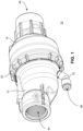
- FIGS. 1 to 5 show a flow-through type pressure regulator 10 in perspective, cross-sectional and exploded views, respectively.
- the pressure regulator 10 includes a housing formed by an inlet cap 12 and an outlet cap 14.
- the inlet and outlet caps are connected by a snap connection, but may be connected by a threaded connection, friction fit connection or other connection. The connection may or may not allow the inlet and outlet caps to be separated after assembly of the pressure regulator.
- the inlet cap 12 has an end portion with an annular connector 16 that may be formed by an annular row of teeth.
- an end of the outlet cap 14 has an annular connector 18 at an end portion therefore.
- Each connector 16, 18 may have an annular row of teeth. The teeth of one connector slide between the teeth of the other connector when the inlet cap and outlet caps are pushed together.
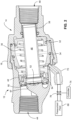
- a hollow, annular liner 22 is housed by and is between the inlet and outlet caps.
- An inner surface 24 of the liner 22 forms a radially inward surface of a sealed chamber 26 within the pressure regulator.
- An outer surface of the liner 22 has an annular ledge 28 that abuts an annular edge of the connector 16 of the inlet cap 12.
- An annular end 30 of the liner abuts an annular ledge on the outlet cap 14. The liner 22 is secured in the pressure regulator by the inlet and outlet caps 12 and 14.
- O-ring seals 32, 34 are in grooves or recesses in the outer surface of the liner 22.
- the O-ring seals prevent air or other fluid leaking from the sealed chamber 26, through gaps between the outer surface of the liner and the inner surfaces of inlet and outlet caps, and out to the atmosphere.
- the O-ring seal 32 is seated in a recess at the end 30 of the liner.
- the O-ring 32 is between the outer surface of the liner and the inner surface of the outlet cap 14.
- the O-ring 34 is in a groove in the outer surface of the liner and is between the liner and an inner surface of the inlet cap 12.
- the sealed chamber 26 is in a region within the pressure regulator that has conventionally been used to house a coil spring 36.
- the sealed chamber 26 is bordered by the inner surface of the liner 22, the outer surface of a cylindrical plunger 38, an upstream surface of an annular flange 40 fixed to the plunger, and a downstream surface of an annular shuttle 42.
- the coil spring 36 biases the flange 40 and its plunger 38 towards the outlet cap 14.
- the coil spring also biases the shuttle 42 towards the inlet cap.
- the plunger 38, with its flange 40, moves axially with respect to the chamber 26.
- the shuttle 42 moves axially with respect to the chamber.
- the flow through the pressure regulator 10 depends, in part, on the narrowest gap in the flow passages 44, 46 and 48 in the regulator.
- the liner 22 is secured in the pressure regulator by the inlet and outlet caps 12 and 14.
- the valve seat 52 may have a disc shape with an annular surface configured to abut against an entirety of a circular edge of the inlet 50 to the plunger.
- the area of gap (G) varies depending on the position of the inlet 50 of the plunger 38. The gap is greatest while the plunger is displaced against an annular ledge 56 in the outlet cap.
- the gap (G) is narrowest, and can be substantially closed, if the circular edge of the inlet 50 to the plunger is against the valve seat 52. Movement of the plunger 38 changes the area of the gap (G) and thus water flow through the regulator.
- Movement of the plunger 38 is driven by water pressure at the outlet flow passage 48.
- Water flowing through the outlet flow passage 48 seeps into a chamber 58 between the annular ledge 56 of the outlet cap and the flange 40 of the plunger.
- the water pressure in the chamber 58 is substantially the same as the water pressure in the outlet flow passage 48.
- the water pressure in the outlet passage 48 increases, the water pressure also increases in the chamber 58.
- This increase in water pressure in chamber 58 displaces the flange 40 and plunger 38 towards the valve seat 52.
- the plunger is moved towards the valve seat. This movement reduces the gap (G) and restricts water flow through the regulator.
- Restricting water flow through the gap reduces the water pressure in the plunger flow passage 46 and the outlet flow passage 48.
- the pressure in the chamber 58 likewise reduces and the plunger 38 slides from the valve seat.
- This interaction between the water pressure of the outlet flow passage 48, the movement of the plunger, and the width of the gap (G) which determines the water flow through the regulator provides a regulating function that maintains a generally uniform water pressure flowing from the outlet flow passage 48.
- An O-ring 60 may be seated in a groove in the wall of the outlet flow passage 48.
- the O-ring is in the fluid passage between the outlet flow passage 48 and chamber 58.
- the O-ring 60 does not seal the fluid passage. Rather, the O-ring narrows the passage 48 and thereby slows the flow in and out of the chamber 58. By slowing the flow, the rate of pressure change in the chamber 58 is dampened to avoid too quick movements, e.g., vibration, of the plunger 38.
- the O-ring and its operation is described in detail in U.S. Patent 5,257,646 , which is incorporated by reference.
- An O-ring seal 62 is in an annular outer wall 64 of the flange 40 of the plunger 38.
- the O-ring seal 62 prevents water or other fluid flow into or out of the sealed chamber 26 and into the chamber 58 between the flange 40 and the ledge 56 of the outlet cap.
- the O-ring seal 62 is retained in a groove in the outer wall 64 of the flange.
- the O-ring 62 slides against the inner wall 24 of the liner as the plunger moves back and forth along its axis with respect to the liner 22.
- Other means may be used for preventing flow out or into the chamber 26 and between the liner 22 and the outer wall 64 of the flange 40 of the plunger.
- a diaphragm extending from the flange 40 and liner 22 may be used to seal the chamber 26 housing the spring from the chamber 58 between the plunger flange 40 and the ledge 56 in the outlet cap 14.
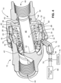
- the sealed chamber 26 is pressurized via a pressure port 66 that provides a fluid connection between the chamber 26 and a source 68 of a pressurized fluid, such as a source of pressurized air.
- the port may be a conduit extending through a stem 70 attached to a sidewall of the inlet cap 12.
- the stem 70 includes a connector 72 that may connect to a hose linking the pressurized fluid source 68 to the port 66.
- the outlet of the port is open to the sealed chamber 26.
- the shuttle 42 may be configured to operate as an on-off valve for water flow through the pressure regulator 10. To shut off water flow, the shuttle 42 moves upstream to the valve seat 52.
- the shuttle has an inner wall that slides over an outer rim of the valve seat 52 and its strut 54.
- the sealed chamber 26 may be pressurized from the source of a pressurized fluid 68 to move the shuttle 42 to the off position such that the shuttle covers the valve seat 52 and thereby closes the water flow passage into the inlet 50 to the plunger flow passage 46.
- the pressure in the sealed chamber must be sufficient to overcome the water pressure in the inlet flow passage 44 that acts on the front face of the shuttle 42.
- the force of the spring 36 assists the force applied by the pressure in the sealed chamber 26 to move the shuttle to the closed position.
- pressure in the sealed chamber 26 is released by venting through the port 66 to the atmosphere or a vacuum. Releasing the pressure allows the sealed chamber 26 to be near or below atmospheric pressure, when the sealed chamber 58 is not pressurized, the water pressure in the inlet flow passage 44 overcomes the force of the spring 36 and moves the shuttle in a downstream direction and thereby opens the flow passage.
- the shuttle 42 By controlling the pressure in the sealed chamber 26, the shuttle 42 may be moved to turn on and off water flow through the pressure regulator 10.
- the pressure in the sealed chamber 26 may be controlled by a controller 74 that actuates a valve 76 connected to the port 66 for the sealed chamber.
- the valve may have an open position that allows pressurized fluid from the source of the pressurized fluid 68 to flow into the sealed chamber 26, and a vent position that allows pressure from the sealed chamber 26 to vent to the atmosphere.
- the valve may also have a closed position that prevents gas flowing out of the port 66.
- the controller 74 may be a computer control system or processor that communicates via a wired or wireless link with a respective valve 76 for each of the pressure regulators in an irrigation system. Similarly, a valve 76 may control the fluid pressure applied to a group of pressure regulators. The valve 76 for each pressure regulator or group of regulators may include an actuator which is controlled by the controller and turns the valve to its different positions.
- the controller 74 may be configured to control each pressure regulator 10 to turn on and off water flow in accordance with a schedule set by an operator or set in accordance with the agriculture crop to be irrigated or the field to be irrigated.
- the schedule may be that for every 30-second interval the pressure regulator allows water flow for a certain period, such as 20 seconds, and turns off the water flow for 10 seconds.
- This schedule of turning on and off water flow may be used for all the pressure regulators in an irrigation system.
- the schedule is achieved by having the controller 74 command the valves 76 for all the pressure regulators to pressurize and vent the sealed chambers in the pressure regulators based on the schedule.
- the shuttle may function as an automatic shut-off for the pressure regulator.
- This automatic shut-off function is independent of the controller and is operable while the sealed chamber 26 is near or below atmospheric pressure.
- the shut-off function may be to shut off water flow through the pressure regulator automatically when the water pressure at the inlet passage 44 falls below a threshold pressure level.
- the automatic shut-off operates based on the force the spring 36 applies to the shuttle 42.
- the shuttle 42 is biased by the spring 36 towards an upstream position that shuts off water flow through the pressure regulator. If the water pressure at the inlet flow passage 44 is not sufficient to overcome the spring force applied to the shuttle, then the spring 36 keeps the shuttle 42 biased in an upstream direction and thereby closes the gap between the plunger inlet 50 and the valve seat 52.
- the shuttle is moved from the shut-off position by water pressure in the inlet flow passage 44 that acts on the front face of the shuttle. As the water pressure increases in the inlet flow passage, the shuttle 42 is moved towards a downstream position that creates an opening between the shuttle, the valve seat 52 and the inlet 50 of the plunger 38. This opening allows water to flow through the pressure regulator 10.
- the water pressure at the inlet flow passage 44 needed to move the shuttle 42 and thereby open the pressure regulator to water flow may be a predetermined threshold pressure level.
- the shuttle may be configured to shut off water flow through the pressure regulator 10 while the water pressure at the inlet flow passage 44 is below the threshold pressure level.
- Pressurizing the sealed chamber 26 with enough pressure from the source 68 of the pressurized fluid will overcome the water pressure in the inlet flow passage and move the shuttle 42 to an upstream position to stop water flow.
- FIG. 5 shows the shuttle 42 in partial cross section and in a perspective view.
- the shuttle 42 includes a front face 78 that faces upstream towards the water flow coming through the inlet flow passage 44.
- the front face 78 is annular and may have a concave shape in cross section.
- Ribs 80 may be arranged symmetrically around the front face 78. The concave shape of the front face and the ribs 80 assist in directing water from the front face radially inward towards a gap between the shuttle and the valve seat.
- An annular slot 82 in the rear of the shuttle 42 is configured to receive the coil spring 36.
- the shuttle 42 has an outer cylindrical surface 84 and an inner cylindrical surface 86. Both surfaces 84, 86 have grooves to receive respective O-ring seals 88, 90.
- the O-ring seal 88 in the annular groove on outer cylindrical surface 84 forms a water tight seal between the shuttle and an inner cylindrical surface 87 of the inlet cap 12.
- the O-ring seal 90 in the annular groove on the inner cylindrical surface 86 forms a water tight seal between the shuttle 42 and an outer cylindrical surface ( FIG. 3 ) of the plunger 38.
- These O-ring seals 88, 90 remain in their respective grooves of the shuttle and slide against the surfaces of the inlet cap or plunger.
- the shuttle 42 also includes a second set of O-ring seals 92, 94 that assists in providing a water tight seal with the valve seat 52 while the shuttle is its upstream-most position in the inlet cap 12.
- the O-ring 92 is in a groove on an inner cylindrical surface 96 which has a larger diameter than does the inner radial surface 86 which seats the O-ring 90.
- O-ring 92 has a larger diameter and is radially outward of the other O-ring 90 on the inner surface 86 of the shuttle 42. Because of its larger diameter, the O-ring 92 does not abut or slide against the outer surface of the plunger 38.
- the O-ring 92 is sized to form a seal with an outer cylindrical surface 97 ( FIG.
- the O-ring 92 engages the surface 97 of the strut 54 only while the shuttle 42 is in the upstream-most position.
- the O-ring 92 forms a water tight seal against the surface 97 of the strut, while the shuttle is in the upstream-most position.
- the O-ring 92 does not form a water tight seal while the shuttle 42 is moved downstream and the O-ring 92 is not engaged with the surface 97 of the strut.
- the O-ring 94 is seated in a groove in an outer cylindrical surface 98 of the shuttle 42, which is radially inward of the outer cylindrical surface 84.
- the O-ring 94 has a smaller diameter and is radially inward of the O-ring 88.
- O-ring 94 does not abut and does not slide against the same cylindrical surface 87 against which slides O-ring 88.
- the O-ring 94 engages and seals against a cylindrical surface 100 ( FIG. 3 ) on the inlet cap and in the inlet flow passage 44.
- the surface 100 has a narrower diameter than the cylindrical surface 87 which is also on the inlet cap and in the inlet flow passage 44.
- a small annular step 102 or ramp transitions the inlet flow passage between the surfaces 87 and 100.
- the O-ring 94 abuts and forms a water tight seal with the cylindrical surface 100 while the shuttle 42 is at the upstream-most position.
- the shuttle may move quickly between the shut-off and open positions. Similarly, it may be desirable to avoid a position in which the shuttle is, for extended periods, in an intermediate position between the upstream-most and downstream-most positions. If left in an intermediate position, the shuttle may reduce water flow through the pressure regulator in an undesired manner.
- the O-ring 94 and annular step 102 assists in transitioning the shuttle from a shut-off position (where the shuttle is in the most upstream position) to an open position (where the shuttle is moved to a downstream-most position).
- the O-ring 94 slides away from the inner surface 100 on the inlet cap, water flows around the O-ring and acts on the annular step 102 in addition to the front face 78 of the shuttle 42.
- the force applied by the water to the shuttle similarly increases as the O-ring slides from the inner surface 100. The increase in the force applied by the water to the shuttle acts to move the shuttle quickly to the downstream-most position.
- the invention may also be embodied as a flow control device that does not regulate the pressure of liquid, such as water, flowing through the device.
- the structure of such as device may be the same as shown in FIGS. 1 to 6 , except that the plunger need not move with respect to the housing.
- the plunger may be fixed in position in the housing, e.g., inlet cap and outlet cap, by the liner 22 and outlet cap 14. If the plunger is fixed to the housing, the plunger is not capable of moving axially towards the valve seat and thereby regulate a pressure drop through the gap (G) between the inlet of the plunger 50 and the valve seat 52. If the plunger is fixed, it may be a fixed flow conduit within the housing.
Landscapes
- Physics & Mathematics (AREA)
- Engineering & Computer Science (AREA)
- Fluid Mechanics (AREA)
- General Physics & Mathematics (AREA)
- Automation & Control Theory (AREA)
- General Engineering & Computer Science (AREA)
- Mechanical Engineering (AREA)
- Power Engineering (AREA)
- Control Of Fluid Pressure (AREA)
Claims (14)
- Druckregler (10), umfassend:ein Gehäuse (12, 14) mit einem Strömungskanal (44, 46, 48);einen Kolben (38), der konfiguriert ist für eine Bewegung in dem Gehäuse, wobei der Kolben hohl ist und einen Kolbenkanal (46) aufweist, der in dem Strömungskanal enthalten ist;einen Ventilsitz (52) in dem Gehäuse, der in dem Strömungskanal unmittelbar stromaufwärts eines Einlasses (50) zu dem Kolbenkanal (46) angeordnet ist;gekennzeichnet durcheinen Schieber (42) in dem Gehäuse, der konfiguriert ist für eine Bewegung zwischen einer äußersten stromaufwärts gelegenen Position, in der der Schieber an dem Ventilsitz anliegt, um den Strömungskanal zu schließen, und einer stromabwärts gelegenen Position, die von dem Ventilsitz verlagert ist und den Strömungskanal öffnet;eine abgedichtete Kammer (26) in dem Gehäuse und zwischen dem Kolben und dem Schieber, wobei die abgedichtete Kammer für einen Betrieb mit anderen Drücken als dem Atmosphärendruck ausgebildet ist; undeine Öffnung (66) in dem Gehäuse, die zu der abgedichteten Kammer offen ist, wobei die Öffnung für eine Verbindung mit einer Quelle (68) eines unter Druck stehenden Fluids konfiguriert ist.
- Druckregler nach Anspruch 1, ferner umfassend eine Feder (36) in der abgedichteten Kammer (26), wobei ein Ende der Feder an den Schieber (42) drückt und ein gegenüberliegendes Ende der Feder an einen Flansch (40) des Kolbens (38) drückt.
- Druckregler nach Anspruch 1 oder 2, wobei die Quelle (68) des unter Druck stehenden Fluids eine Druckgasquelle ist.
- Druckregler nach Anspruch 1, ferner umfassend ein Ventil (76), das mit der Öffnung (66) verbunden ist, wobei das Ventil eine erste Position aufweist, in der das unter Druck stehende Fluid aus der Quelle (68) des unter Druck stehenden Fluids in die abgedichtete Kammer (26) einströmt, und eine zweite Position, in der das Fluid zur Druckentlastung in der Kammer aus der Kammer ausströmt.
- Druckregler nach Anspruch 1, ferner umfassend eine Steuereinheit (74), die derart konfiguriert ist, dass sie die abgedichtete Kammer (26) gemäß einem Druckbeaufschlagungszyklus mit Druck beaufschlagt.
- Druckregler nach Anspruch 1, wobei der Schieber (42) aufweist:eine erste innere zylindrische Fläche (87) mit einer ersten Dichtung (90), die für einen gleitenden Eingriff mit dem Kolben ausgebildet ist,und eine zweite innere zylindrische Fläche (96) mit einer zweiten Dichtung (92), die für einen Eingriff mit dem Ventilsitz (52) ausgebildet ist,wobei ein Durchmesser der zweiten inneren zylindrischen Fläche größer ist als ein Durchmesser der ersten inneren zylindrischen Fläche, wobei optional die erste innere zylindrische Fläche (96) eine erste Ringnut aufweist und die erste Dichtung (90) ein in der ersten Ringnut sitzender O-Ring ist und die zweite innere zylindrische Fläche (96) eine zweite Ringnut aufweist und die zweite Dichtung (92) ein in der zweiten Ringnut sitzender O-Ring ist.
- Druckregler nach Anspruch 1, wobei der Schieber (42) ringförmig ist und aufweist:eine erste äußere zylindrische Fläche (84) mit einer dritten Dichtung (88), die für einen gleitenden Eingriff mit einer ersten inneren zylindrischen Fläche (87) des Gehäuses konfiguriert ist, undeine zweite äußere zylindrische Fläche (98) mit einer vierten Dichtung (94), die konfiguriert ist für den Eingriff mit einer zweiten inneren zylindrischen Fläche (100) des Gehäuses, während sich der Schieber in der äußersten stromaufwärts gelegenen Position befindet,wobei optional ein Durchmesser der ersten äußeren zylindrischen Fläche (84) des Schiebers größer ist als ein Durchmesser der zweiten äußeren zylindrischen Fläche (98) des Schiebers,wobei die erste äußere zylindrische Fläche (84) des Schiebers eine dritte Ringnut aufweist und die dritte Dichtung (88) ein in der dritten Ringnut sitzender O-Ring ist und wobei die zweite äußere zylindrische Fläche (98) eine vierte Ringnut aufweist und die vierte Dichtung (94) ein in der vierten Ringnut sitzender O-Ring ist.
- Durchflusssteuerungs-/Regelungsvorrichtung (10), umfassend:ein Gehäuse (12, 14) mit einem Strömungskanal (44, 46, 48), der sich von einem Gehäuseeinlass durch das Gehäuse zu einem Gehäuseauslass erstreckt;ein Hohlrohr (38), das einen Rohrdurchlass (46) definiert, der in dem Strömungskanal des Gehäuses enthalten ist;einen Ventilsitz (52) in dem Gehäuse, der in dem Strömungskanal unmittelbar stromaufwärts eines Einlasses (90) des Rohrdurchlasses angeordnet ist;gekennzeichnet durcheinen Schieber (42) in dem Gehäuse, der konfiguriert ist für eine wechselseitige Bewegung hinsichtlich des Gehäuses wie auch des Hohlrohrs, wobei der Schieber in dem Gehäuse eine äußerste stromaufwärts gelegene Position aufweist, in der der Schieber an dem Ventilsitz anliegt und den Strömungskanal schließt, und eine stromabwärts gelegene Position, die von dem Ventilsitz verlagert ist und die den Strömungskanal öffnet;eine abgedichtete Kammer (26) in dem Gehäuse und zwischen dem Hohlrohr und dem Schieber, wobei die abgedichtete Kammer konfiguriert ist für einen Betrieb mit anderen Drücken als dem Atmosphärendruck; undeine Öffnung (66) in dem Gehäuse, die zu der abgedichteten Kammer offen ist, wobei die Öffnung für eine Verbindung mit einer Quelle (68) eines unter Druck gesetzten Fluids konfiguriert ist.
- Durchflusssteuerungs-/Regelungsvorrichtung nach Anspruch 8, ferner umfassend:eine Feder (36) in der abgedichteten Kammer (26), wobei ein Ende der Feder an den Schieber (42) und ein gegenüberliegendes Ende der Feder an einen Flansch (40) des Hohlrohrs drückt, oderein Ventil (76), das mit der Öffnung verbunden ist, wobei das Ventil eine erste Position aufweist, in der ein unter Druck gesetztes Fluid aus der Quelle (68) des unter Druck gesetzten Fluids in die abgedichtete Kammer einströmt, und eine zweite Position, in der zur Druckentlastung der abgedichteten Kammer Fluid aus der abgedichteten Kammer ausströmt,eine Steuereinheit (74), die derart konfiguriert ist, dass sie die abgedichtete Kammer gemäß einem Druckbeaufschlagungszyklus mit Druck beaufschlagt.
- Durchflusssteuerungs-/Regelungsvorrichtung nach Anspruch 8, wobei der Schieber (42) aufweist:eine erste äußere zylindrische Fläche (84) mit einer dritten Dichtung (88), die für einen gleitenden Eingriff mit einer ersten inneren zylindrischen Fläche (87) des Gehäuses konfiguriert ist, undeine zweite äußere zylindrische Fläche (98) mit einer vierten Dichtung (94), die konfiguriert ist für den Eingriff mit einer zweiten inneren zylindrischen Fläche (100) des Gehäuses, während sich der Schieber in der äußersten stromaufwärts gelegenen Position befindet,wobei optional ein Durchmesser der ersten äußeren zylindrischen Fläche (84) des Schiebers größer ist als ein Durchmesser der zweiten äußeren zylindrischen Fläche (98) des Schiebers,wobei die erste äußere zylindrische Fläche (84) des Schiebers eine dritte Ringnut aufweist und die dritte Dichtung (88) ein in der dritten Ringnut sitzender O-Ring ist und wobei die zweite äußere zylindrische Fläche (98) eine vierte Ringnut aufweist und die vierte Dichtung (94) ein in der vierten Ringnut sitzender O-Ring ist.
- Verfahren zum Steuern/Regeln einer Flüssigkeitssteuerungs- /Regelungsvorrichtung (10) mit einem Gehäuse (12, 14), das einen Strömungskanal (44, 46, 48) aufweist, der sich von einem Einlass zu einem Auslass durch das Gehäuse erstreckt, wobei der Strömungskanal zum Teil durch ein Hohlrohr (38) in dem Gehäuse, eine abgedichtete Kammer (26) zwischen dem Hohlrohr und dem Gehäuse definiert wird und durch einen Schieber (42) gekennzeichnet ist, wobei das Verfahren umfasst:Bewegen des Schiebers in dem Gehäuse zum Schließen eines Spalts (G) zwischen einem Ventilsitz (52) in dem Gehäuse und einem Einlass (44) zu dem Hohlrohrdurchlass, wobei die Bewegung des Schiebers angetrieben wird durch Einspritzen eines unter Druck gesetzten Fluids in die abgedichtete Kammer und wobei das Schließen des Spalts den Strömungskanal schließt;und Wegbewegen des Schiebers von dem Ventilsitz, um den Spalt zu öffnen und zu ermöglichen, dass Flüssigkeit in den Einlass des Hohlrohrs und aus dem Auslass des Gehäuses strömt, wobei die Bewegung des Schiebers angetrieben wird durch Ablassen des unter Druck gesetzten Fluids aus der abgedichteten Kammer zur Druckentlastung der abgedichteten Kammer.
- Verfahren nach Anspruch 11, wobei das Einspritzen des unter Druck gesetzten Fluids in die abgedichtete Kammer (26) und die Bewegungen des Schiebers (42) optional nach einem Zeitplan erfolgen,
wobei der Zeitplan einen sich wiederholenden Zyklus enthält mit einer Periode, während der der Schieber (42) an dem Ventilsitz (52) anliegt und der Strömungskanal (G) geschlossen ist, und mit einer weiteren Periode, während der der Schieber (42) von dem Ventilsitz (52) entfernt ist und der Strömungskanal (G) offen ist. - Verfahren nach einem der Ansprüche 11 oder 12, ferner umfassend das Bewegen des Schiebers (42) zur Abdichtung an dem Ventilsitz (52), um den Spalt (G) in dem Strömungskanal zu schließen in Reaktion darauf, dass ein Wasserdruck an einem Einlass zu dem Strömungskanal unter einem Schwellen-Wasserdruck liegt.
- Verfahren nach Anspruch 11, wobei die Bewegung des Schiebers (42) durch eine Feder (36) angetrieben wird, die den Schieber in Richtung auf den Ventilsitz (52) drückt, wobei ein Druck in der abgedichteten Kammer (26) den Schieber in Richtung auf den Ventilsitz drückt,
und durch Flüssigkeitsdruck in dem Gehäuse und stromaufwärts des Ventilsitzes, der den Schieber von dem Ventilsitz abdrückt.
Applications Claiming Priority (2)
| Application Number | Priority Date | Filing Date | Title |
|---|---|---|---|
| US201862658968P | 2018-04-17 | 2018-04-17 | |
| PCT/US2019/027814 WO2019204396A1 (en) | 2018-04-17 | 2019-04-17 | Multi-function pressure regulation valve |
Publications (3)
| Publication Number | Publication Date |
|---|---|
| EP3782003A1 EP3782003A1 (de) | 2021-02-24 |
| EP3782003A4 EP3782003A4 (de) | 2022-01-19 |
| EP3782003B1 true EP3782003B1 (de) | 2024-03-20 |
Family
ID=68160004
Family Applications (1)
| Application Number | Title | Priority Date | Filing Date |
|---|---|---|---|
| EP19788042.0A Active EP3782003B1 (de) | 2018-04-17 | 2019-04-17 | Multifunktionsdruckregelventil |
Country Status (5)
| Country | Link |
|---|---|
| US (1) | US11126208B2 (de) |
| EP (1) | EP3782003B1 (de) |
| CN (1) | CN112236735A (de) |
| AU (1) | AU2019255268B2 (de) |
| WO (1) | WO2019204396A1 (de) |
Families Citing this family (12)
| Publication number | Priority date | Publication date | Assignee | Title |
|---|---|---|---|---|
| US11933408B2 (en) * | 2018-04-17 | 2024-03-19 | Nelson Irrigation Corporation | Multi-function pressure regulation valve |
| US11933417B2 (en) | 2019-09-27 | 2024-03-19 | Rain Bird Corporation | Irrigation sprinkler service valve |
| US11408515B2 (en) * | 2020-01-29 | 2022-08-09 | Nelson Irrigation Corporation | Pressure regulator having an oblique valve seat |
| USD966123S1 (en) | 2020-02-28 | 2022-10-11 | Nelson Irrigation Corporation | Pressure regulator |
| CA3188140A1 (en) | 2020-06-24 | 2021-12-30 | Winston Products Llc | Expandable hose |
| US12030072B2 (en) | 2020-11-16 | 2024-07-09 | Rain Bird Corporation | Pressure regulation device and method for irrigation sprinklers |
| IT202100012794A1 (it) * | 2021-05-18 | 2022-11-18 | Komet Austria Gmbh | Regolatore di pressione per un liquido con flusso deviato |
| EP4286975B1 (de) * | 2022-06-01 | 2024-05-08 | Husqvarna AB | Druckminderer |
| EP4630718A1 (de) * | 2022-12-07 | 2025-10-15 | Engineered Controls International, LLC | Zweistufiger druckregler für druckgas |
| US12222736B2 (en) * | 2022-12-20 | 2025-02-11 | Balboa Water Group, Llc | Flow control valve and spa recirculation system with heat pump using the valve |
| US12443208B2 (en) | 2023-02-08 | 2025-10-14 | Rain Bird Corporation | Control zone devices, systems and methods |
| US12498049B2 (en) | 2024-03-29 | 2025-12-16 | Rain Bird Corporation | Zone control devices, systems and methods |
Family Cites Families (32)
| Publication number | Priority date | Publication date | Assignee | Title |
|---|---|---|---|---|
| US383314A (en) * | 1888-05-22 | Half to horace j | ||
| US2761389A (en) * | 1952-05-09 | 1956-09-04 | Gen Motors Corp | Regulating valves for jet pumps |
| US3515165A (en) * | 1968-10-16 | 1970-06-02 | Vapor Corp | Pressure regulator |
| US3890999A (en) * | 1972-12-15 | 1975-06-24 | Eugene D Moskow | Fluid pressure regulator |
| US3874404A (en) * | 1973-04-05 | 1975-04-01 | Lockheed Aircraft Corp | Check valve |
| US4693267A (en) * | 1986-03-31 | 1987-09-15 | Tescom Corporation | Self-venting pressure reducing regulator |
| US5009368A (en) | 1989-06-21 | 1991-04-23 | Light Ideas Incorporated | Constant-pressure, variable-volume irrigation sprinklers |
| US5246164A (en) | 1991-12-16 | 1993-09-21 | Mccann Ian R | Method and apparatus for variable application of irrigation water and chemicals |
| US5257646A (en) | 1992-08-17 | 1993-11-02 | Nelson Irrigation Corporation | O-ring damped regulator |
| US5427151A (en) * | 1994-05-18 | 1995-06-27 | Simpson Cleaning Systems, Inc. | Pressure regulating chemical injector valve |
| ES2132844T3 (es) * | 1995-11-16 | 1999-08-16 | Boc Group Plc | Valvulas de reduccion de la presion. |
| US5875815A (en) | 1997-10-20 | 1999-03-02 | Nelson Irrigation Corporation | Combination pressure regulator/drain check valve |
| US6374853B1 (en) | 2000-11-30 | 2002-04-23 | Lindsay Manufacturing Company | Combined pressure regulator and shut-off valve |
| US6755362B2 (en) | 2001-10-04 | 2004-06-29 | Neal Krieger | Irrigation system with variable speed drive system |
| US20040007269A1 (en) * | 2002-07-12 | 2004-01-15 | Larsen Todd W. | Inline pressure reducing regulator |
| US6752169B2 (en) * | 2002-10-31 | 2004-06-22 | Lindsay Manufacturing Co. | Pressure regulator and shut-off valve |
| US6923205B2 (en) * | 2002-10-31 | 2005-08-02 | Lindsay Manufacturing Co. | Pressure regulator and shut-off valve |
| US6938842B2 (en) | 2003-05-23 | 2005-09-06 | Lindsay Manufacturing Company | Flow control for irrigation machines |
| US7048001B2 (en) | 2004-04-13 | 2006-05-23 | Nelson Irrigation Corporation | Pressure regulator with single strut regulator seat |
| US7401622B2 (en) | 2006-06-09 | 2008-07-22 | Nelson Irrigation Corporation | Modular pressure regulator |
| US7805221B2 (en) | 2007-05-17 | 2010-09-28 | Rain Bird Corporation | Automatically adjusting irrigation controller |
| US20100032493A1 (en) | 2008-08-06 | 2010-02-11 | Kevin Abts | Precision variable rate irrigation system |
| US9128489B2 (en) | 2010-02-09 | 2015-09-08 | Nelson Irrigation Corporation | Inductively coupled distributed control system |
| US8567433B2 (en) | 2011-03-11 | 2013-10-29 | Nelson Irrigation Corporation | Pressure regulator with manual shut-off valve |
| US9459631B2 (en) | 2011-05-11 | 2016-10-04 | Senninger Irrigation, Inc. | Pressure regulator seat assembly |
| US8678029B2 (en) * | 2011-05-11 | 2014-03-25 | Nelson Irrigation Corporation | Pressure regulator with remotely controlled shut-off valve |
| LU92040B1 (fr) * | 2012-07-09 | 2014-01-10 | Luxembourg Patent Co | Robinet detendeur avec fonction de pression residuelle integree dans le detendeur |
| US9367070B2 (en) | 2014-04-14 | 2016-06-14 | Nelson Irrigation Corporation | Pressure regulator having single strut seat with strut coaxial to plunger |
| ITUB20150884A1 (it) | 2015-05-25 | 2016-11-25 | Arno Drechsel | Dispositivo regolatore di pressione per un liquido |
| LU93061B1 (en) * | 2016-05-09 | 2017-12-22 | Luxembourg Patent Co | Compressed gas regulator with integrated pressure relief valve |
| EP3593021B1 (de) | 2017-03-05 | 2021-12-01 | Bermad CS Ltd. | Druckminderndes ventil mit absperrung |
| US10906052B2 (en) * | 2017-05-26 | 2021-02-02 | Nelson Irrigation Corporation | Drain check in pressure regulator |
-
2019
- 2019-04-17 AU AU2019255268A patent/AU2019255268B2/en active Active
- 2019-04-17 WO PCT/US2019/027814 patent/WO2019204396A1/en not_active Ceased
- 2019-04-17 EP EP19788042.0A patent/EP3782003B1/de active Active
- 2019-04-17 CN CN201980026246.7A patent/CN112236735A/zh active Pending
- 2019-04-17 US US16/386,899 patent/US11126208B2/en active Active
Also Published As
| Publication number | Publication date |
|---|---|
| WO2019204396A1 (en) | 2019-10-24 |
| AU2019255268A1 (en) | 2020-10-22 |
| AU2019255268B2 (en) | 2024-03-07 |
| EP3782003A4 (de) | 2022-01-19 |
| US11126208B2 (en) | 2021-09-21 |
| BR112020021284A2 (pt) | 2021-01-26 |
| US20190317534A1 (en) | 2019-10-17 |
| EP3782003A1 (de) | 2021-02-24 |
| CN112236735A (zh) | 2021-01-15 |
Similar Documents
| Publication | Publication Date | Title |
|---|---|---|
| EP3782003B1 (de) | Multifunktionsdruckregelventil | |
| US11933408B2 (en) | Multi-function pressure regulation valve | |
| EP1342141B1 (de) | Kombinierter druckregler und verschlussventil | |
| CA2502737C (en) | Pressure regulator and shut-off valve | |
| US7475863B2 (en) | Piston for reverse flow diaphragm valve | |
| US20040261859A1 (en) | Pressure regulator and shut-off valve | |
| US20110226354A1 (en) | Flow Controller | |
| US10302209B2 (en) | Stabilizer cartridge for a fluid regulator | |
| WO2018051150A1 (en) | Flowrate stabilising monoblock cartridge for hydraulic valves | |
| US4314582A (en) | Combined pressure-regulator and manual shut-off valve | |
| US9662752B2 (en) | Method and apparatus for damping an actuator on a fluid regulator | |
| CN111102365B (zh) | 流体调节器 | |
| US20210046498A1 (en) | Sprinkler elbow connector with integral pressure regulator | |
| BR112020021284B1 (pt) | Válvula de regulagem de pressão multifuncional | |
| JP7572182B2 (ja) | 弁装置 | |
| CN114207546A (zh) | 用于先导阀的致动器 | |
| WO2005045546A1 (en) | Combined pressure regulator and shut-off valve | |
| GB1576677A (en) | Gas valve assembly |
Legal Events
| Date | Code | Title | Description |
|---|---|---|---|
| STAA | Information on the status of an ep patent application or granted ep patent |
Free format text: STATUS: THE INTERNATIONAL PUBLICATION HAS BEEN MADE |
|
| PUAI | Public reference made under article 153(3) epc to a published international application that has entered the european phase |
Free format text: ORIGINAL CODE: 0009012 |
|
| STAA | Information on the status of an ep patent application or granted ep patent |
Free format text: STATUS: REQUEST FOR EXAMINATION WAS MADE |
|
| 17P | Request for examination filed |
Effective date: 20201028 |
|
| AK | Designated contracting states |
Kind code of ref document: A1 Designated state(s): AL AT BE BG CH CY CZ DE DK EE ES FI FR GB GR HR HU IE IS IT LI LT LU LV MC MK MT NL NO PL PT RO RS SE SI SK SM TR |
|
| AX | Request for extension of the european patent |
Extension state: BA ME |
|
| DAV | Request for validation of the european patent (deleted) | ||
| DAX | Request for extension of the european patent (deleted) | ||
| A4 | Supplementary search report drawn up and despatched |
Effective date: 20211216 |
|
| RIC1 | Information provided on ipc code assigned before grant |
Ipc: G05D 16/20 20060101ALI20211210BHEP Ipc: G05D 16/10 20060101ALI20211210BHEP Ipc: G05D 16/04 20060101ALI20211210BHEP Ipc: B05B 1/00 20060101ALI20211210BHEP Ipc: F16K 17/00 20060101ALI20211210BHEP Ipc: G05D 16/00 20060101AFI20211210BHEP |
|
| GRAP | Despatch of communication of intention to grant a patent |
Free format text: ORIGINAL CODE: EPIDOSNIGR1 |
|
| STAA | Information on the status of an ep patent application or granted ep patent |
Free format text: STATUS: GRANT OF PATENT IS INTENDED |
|
| RIC1 | Information provided on ipc code assigned before grant |
Ipc: F16K 15/08 20060101ALI20230615BHEP Ipc: G05D 16/20 20060101ALI20230615BHEP Ipc: G05D 16/10 20060101ALI20230615BHEP Ipc: G05D 16/04 20060101ALI20230615BHEP Ipc: B05B 1/00 20060101ALI20230615BHEP Ipc: F16K 17/00 20060101ALI20230615BHEP Ipc: G05D 16/00 20060101AFI20230615BHEP |
|
| INTG | Intention to grant announced |
Effective date: 20230703 |
|
| GRAJ | Information related to disapproval of communication of intention to grant by the applicant or resumption of examination proceedings by the epo deleted |
Free format text: ORIGINAL CODE: EPIDOSDIGR1 |
|
| STAA | Information on the status of an ep patent application or granted ep patent |
Free format text: STATUS: REQUEST FOR EXAMINATION WAS MADE |
|
| GRAP | Despatch of communication of intention to grant a patent |
Free format text: ORIGINAL CODE: EPIDOSNIGR1 |
|
| INTC | Intention to grant announced (deleted) | ||
| STAA | Information on the status of an ep patent application or granted ep patent |
Free format text: STATUS: GRANT OF PATENT IS INTENDED |
|
| P01 | Opt-out of the competence of the unified patent court (upc) registered |
Effective date: 20231024 |
|
| INTG | Intention to grant announced |
Effective date: 20231109 |
|
| GRAS | Grant fee paid |
Free format text: ORIGINAL CODE: EPIDOSNIGR3 |
|
| GRAA | (expected) grant |
Free format text: ORIGINAL CODE: 0009210 |
|
| STAA | Information on the status of an ep patent application or granted ep patent |
Free format text: STATUS: THE PATENT HAS BEEN GRANTED |
|
| AK | Designated contracting states |
Kind code of ref document: B1 Designated state(s): AL AT BE BG CH CY CZ DE DK EE ES FI FR GB GR HR HU IE IS IT LI LT LU LV MC MK MT NL NO PL PT RO RS SE SI SK SM TR |
|
| REG | Reference to a national code |
Ref country code: GB Ref legal event code: FG4D |
|
| REG | Reference to a national code |
Ref country code: CH Ref legal event code: EP |
|
| REG | Reference to a national code |
Ref country code: IE Ref legal event code: FG4D |
|
| REG | Reference to a national code |
Ref country code: DE Ref legal event code: R096 Ref document number: 602019048665 Country of ref document: DE |
|
| PG25 | Lapsed in a contracting state [announced via postgrant information from national office to epo] |
Ref country code: LT Free format text: LAPSE BECAUSE OF FAILURE TO SUBMIT A TRANSLATION OF THE DESCRIPTION OR TO PAY THE FEE WITHIN THE PRESCRIBED TIME-LIMIT Effective date: 20240320 |
|
| REG | Reference to a national code |
Ref country code: LT Ref legal event code: MG9D |
|
| PG25 | Lapsed in a contracting state [announced via postgrant information from national office to epo] |
Ref country code: GR Free format text: LAPSE BECAUSE OF FAILURE TO SUBMIT A TRANSLATION OF THE DESCRIPTION OR TO PAY THE FEE WITHIN THE PRESCRIBED TIME-LIMIT Effective date: 20240621 |
|
| PG25 | Lapsed in a contracting state [announced via postgrant information from national office to epo] |
Ref country code: RS Free format text: LAPSE BECAUSE OF FAILURE TO SUBMIT A TRANSLATION OF THE DESCRIPTION OR TO PAY THE FEE WITHIN THE PRESCRIBED TIME-LIMIT Effective date: 20240620 Ref country code: HR Free format text: LAPSE BECAUSE OF FAILURE TO SUBMIT A TRANSLATION OF THE DESCRIPTION OR TO PAY THE FEE WITHIN THE PRESCRIBED TIME-LIMIT Effective date: 20240320 |
|
| REG | Reference to a national code |
Ref country code: NL Ref legal event code: MP Effective date: 20240320 |
|
| PG25 | Lapsed in a contracting state [announced via postgrant information from national office to epo] |
Ref country code: RS Free format text: LAPSE BECAUSE OF FAILURE TO SUBMIT A TRANSLATION OF THE DESCRIPTION OR TO PAY THE FEE WITHIN THE PRESCRIBED TIME-LIMIT Effective date: 20240620 Ref country code: NO Free format text: LAPSE BECAUSE OF FAILURE TO SUBMIT A TRANSLATION OF THE DESCRIPTION OR TO PAY THE FEE WITHIN THE PRESCRIBED TIME-LIMIT Effective date: 20240620 Ref country code: LT Free format text: LAPSE BECAUSE OF FAILURE TO SUBMIT A TRANSLATION OF THE DESCRIPTION OR TO PAY THE FEE WITHIN THE PRESCRIBED TIME-LIMIT Effective date: 20240320 Ref country code: HR Free format text: LAPSE BECAUSE OF FAILURE TO SUBMIT A TRANSLATION OF THE DESCRIPTION OR TO PAY THE FEE WITHIN THE PRESCRIBED TIME-LIMIT Effective date: 20240320 Ref country code: GR Free format text: LAPSE BECAUSE OF FAILURE TO SUBMIT A TRANSLATION OF THE DESCRIPTION OR TO PAY THE FEE WITHIN THE PRESCRIBED TIME-LIMIT Effective date: 20240621 Ref country code: FI Free format text: LAPSE BECAUSE OF FAILURE TO SUBMIT A TRANSLATION OF THE DESCRIPTION OR TO PAY THE FEE WITHIN THE PRESCRIBED TIME-LIMIT Effective date: 20240320 Ref country code: BG Free format text: LAPSE BECAUSE OF FAILURE TO SUBMIT A TRANSLATION OF THE DESCRIPTION OR TO PAY THE FEE WITHIN THE PRESCRIBED TIME-LIMIT Effective date: 20240320 |
|
| PG25 | Lapsed in a contracting state [announced via postgrant information from national office to epo] |
Ref country code: SE Free format text: LAPSE BECAUSE OF FAILURE TO SUBMIT A TRANSLATION OF THE DESCRIPTION OR TO PAY THE FEE WITHIN THE PRESCRIBED TIME-LIMIT Effective date: 20240320 Ref country code: LV Free format text: LAPSE BECAUSE OF FAILURE TO SUBMIT A TRANSLATION OF THE DESCRIPTION OR TO PAY THE FEE WITHIN THE PRESCRIBED TIME-LIMIT Effective date: 20240320 |
|
| PG25 | Lapsed in a contracting state [announced via postgrant information from national office to epo] |
Ref country code: NL Free format text: LAPSE BECAUSE OF FAILURE TO SUBMIT A TRANSLATION OF THE DESCRIPTION OR TO PAY THE FEE WITHIN THE PRESCRIBED TIME-LIMIT Effective date: 20240320 |
|
| PG25 | Lapsed in a contracting state [announced via postgrant information from national office to epo] |
Ref country code: NL Free format text: LAPSE BECAUSE OF FAILURE TO SUBMIT A TRANSLATION OF THE DESCRIPTION OR TO PAY THE FEE WITHIN THE PRESCRIBED TIME-LIMIT Effective date: 20240320 |
|
| PG25 | Lapsed in a contracting state [announced via postgrant information from national office to epo] |
Ref country code: IS Free format text: LAPSE BECAUSE OF FAILURE TO SUBMIT A TRANSLATION OF THE DESCRIPTION OR TO PAY THE FEE WITHIN THE PRESCRIBED TIME-LIMIT Effective date: 20240720 |
|
| PG25 | Lapsed in a contracting state [announced via postgrant information from national office to epo] |
Ref country code: SM Free format text: LAPSE BECAUSE OF FAILURE TO SUBMIT A TRANSLATION OF THE DESCRIPTION OR TO PAY THE FEE WITHIN THE PRESCRIBED TIME-LIMIT Effective date: 20240320 Ref country code: PT Free format text: LAPSE BECAUSE OF FAILURE TO SUBMIT A TRANSLATION OF THE DESCRIPTION OR TO PAY THE FEE WITHIN THE PRESCRIBED TIME-LIMIT Effective date: 20240722 |
|
| PG25 | Lapsed in a contracting state [announced via postgrant information from national office to epo] |
Ref country code: ES Free format text: LAPSE BECAUSE OF FAILURE TO SUBMIT A TRANSLATION OF THE DESCRIPTION OR TO PAY THE FEE WITHIN THE PRESCRIBED TIME-LIMIT Effective date: 20240320 |
|
| PG25 | Lapsed in a contracting state [announced via postgrant information from national office to epo] |
Ref country code: EE Free format text: LAPSE BECAUSE OF FAILURE TO SUBMIT A TRANSLATION OF THE DESCRIPTION OR TO PAY THE FEE WITHIN THE PRESCRIBED TIME-LIMIT Effective date: 20240320 Ref country code: CZ Free format text: LAPSE BECAUSE OF FAILURE TO SUBMIT A TRANSLATION OF THE DESCRIPTION OR TO PAY THE FEE WITHIN THE PRESCRIBED TIME-LIMIT Effective date: 20240320 |
|
| PG25 | Lapsed in a contracting state [announced via postgrant information from national office to epo] |
Ref country code: PL Free format text: LAPSE BECAUSE OF FAILURE TO SUBMIT A TRANSLATION OF THE DESCRIPTION OR TO PAY THE FEE WITHIN THE PRESCRIBED TIME-LIMIT Effective date: 20240320 |
|
| PG25 | Lapsed in a contracting state [announced via postgrant information from national office to epo] |
Ref country code: SK Free format text: LAPSE BECAUSE OF FAILURE TO SUBMIT A TRANSLATION OF THE DESCRIPTION OR TO PAY THE FEE WITHIN THE PRESCRIBED TIME-LIMIT Effective date: 20240320 |
|
| PG25 | Lapsed in a contracting state [announced via postgrant information from national office to epo] |
Ref country code: SM Free format text: LAPSE BECAUSE OF FAILURE TO SUBMIT A TRANSLATION OF THE DESCRIPTION OR TO PAY THE FEE WITHIN THE PRESCRIBED TIME-LIMIT Effective date: 20240320 Ref country code: SK Free format text: LAPSE BECAUSE OF FAILURE TO SUBMIT A TRANSLATION OF THE DESCRIPTION OR TO PAY THE FEE WITHIN THE PRESCRIBED TIME-LIMIT Effective date: 20240320 Ref country code: RO Free format text: LAPSE BECAUSE OF FAILURE TO SUBMIT A TRANSLATION OF THE DESCRIPTION OR TO PAY THE FEE WITHIN THE PRESCRIBED TIME-LIMIT Effective date: 20240320 Ref country code: PT Free format text: LAPSE BECAUSE OF FAILURE TO SUBMIT A TRANSLATION OF THE DESCRIPTION OR TO PAY THE FEE WITHIN THE PRESCRIBED TIME-LIMIT Effective date: 20240722 Ref country code: PL Free format text: LAPSE BECAUSE OF FAILURE TO SUBMIT A TRANSLATION OF THE DESCRIPTION OR TO PAY THE FEE WITHIN THE PRESCRIBED TIME-LIMIT Effective date: 20240320 Ref country code: IS Free format text: LAPSE BECAUSE OF FAILURE TO SUBMIT A TRANSLATION OF THE DESCRIPTION OR TO PAY THE FEE WITHIN THE PRESCRIBED TIME-LIMIT Effective date: 20240720 Ref country code: ES Free format text: LAPSE BECAUSE OF FAILURE TO SUBMIT A TRANSLATION OF THE DESCRIPTION OR TO PAY THE FEE WITHIN THE PRESCRIBED TIME-LIMIT Effective date: 20240320 Ref country code: EE Free format text: LAPSE BECAUSE OF FAILURE TO SUBMIT A TRANSLATION OF THE DESCRIPTION OR TO PAY THE FEE WITHIN THE PRESCRIBED TIME-LIMIT Effective date: 20240320 Ref country code: CZ Free format text: LAPSE BECAUSE OF FAILURE TO SUBMIT A TRANSLATION OF THE DESCRIPTION OR TO PAY THE FEE WITHIN THE PRESCRIBED TIME-LIMIT Effective date: 20240320 |
|
| REG | Reference to a national code |
Ref country code: DE Ref legal event code: R119 Ref document number: 602019048665 Country of ref document: DE |
|
| REG | Reference to a national code |
Ref country code: CH Ref legal event code: PL |
|
| PG25 | Lapsed in a contracting state [announced via postgrant information from national office to epo] |
Ref country code: IT Free format text: LAPSE BECAUSE OF FAILURE TO SUBMIT A TRANSLATION OF THE DESCRIPTION OR TO PAY THE FEE WITHIN THE PRESCRIBED TIME-LIMIT Effective date: 20240320 |
|
| PG25 | Lapsed in a contracting state [announced via postgrant information from national office to epo] |
Ref country code: LU Free format text: LAPSE BECAUSE OF NON-PAYMENT OF DUE FEES Effective date: 20240417 |
|
| REG | Reference to a national code |
Ref country code: BE Ref legal event code: MM Effective date: 20240430 |
|
| PG25 | Lapsed in a contracting state [announced via postgrant information from national office to epo] |
Ref country code: LU Free format text: LAPSE BECAUSE OF NON-PAYMENT OF DUE FEES Effective date: 20240417 Ref country code: IT Free format text: LAPSE BECAUSE OF FAILURE TO SUBMIT A TRANSLATION OF THE DESCRIPTION OR TO PAY THE FEE WITHIN THE PRESCRIBED TIME-LIMIT Effective date: 20240320 |
|
| PG25 | Lapsed in a contracting state [announced via postgrant information from national office to epo] |
Ref country code: MC Free format text: LAPSE BECAUSE OF FAILURE TO SUBMIT A TRANSLATION OF THE DESCRIPTION OR TO PAY THE FEE WITHIN THE PRESCRIBED TIME-LIMIT Effective date: 20240320 |
|
| PG25 | Lapsed in a contracting state [announced via postgrant information from national office to epo] |
Ref country code: DE Free format text: LAPSE BECAUSE OF NON-PAYMENT OF DUE FEES Effective date: 20241105 |
|
| PG25 | Lapsed in a contracting state [announced via postgrant information from national office to epo] |
Ref country code: DK Free format text: LAPSE BECAUSE OF FAILURE TO SUBMIT A TRANSLATION OF THE DESCRIPTION OR TO PAY THE FEE WITHIN THE PRESCRIBED TIME-LIMIT Effective date: 20240320 |
|
| PG25 | Lapsed in a contracting state [announced via postgrant information from national office to epo] |
Ref country code: BE Free format text: LAPSE BECAUSE OF NON-PAYMENT OF DUE FEES Effective date: 20240430 |
|
| PLBE | No opposition filed within time limit |
Free format text: ORIGINAL CODE: 0009261 |
|
| STAA | Information on the status of an ep patent application or granted ep patent |
Free format text: STATUS: NO OPPOSITION FILED WITHIN TIME LIMIT |
|
| PG25 | Lapsed in a contracting state [announced via postgrant information from national office to epo] |
Ref country code: MC Free format text: LAPSE BECAUSE OF FAILURE TO SUBMIT A TRANSLATION OF THE DESCRIPTION OR TO PAY THE FEE WITHIN THE PRESCRIBED TIME-LIMIT Effective date: 20240320 Ref country code: DK Free format text: LAPSE BECAUSE OF FAILURE TO SUBMIT A TRANSLATION OF THE DESCRIPTION OR TO PAY THE FEE WITHIN THE PRESCRIBED TIME-LIMIT Effective date: 20240320 Ref country code: DE Free format text: LAPSE BECAUSE OF NON-PAYMENT OF DUE FEES Effective date: 20241105 Ref country code: BE Free format text: LAPSE BECAUSE OF NON-PAYMENT OF DUE FEES Effective date: 20240430 Ref country code: CH Free format text: LAPSE BECAUSE OF NON-PAYMENT OF DUE FEES Effective date: 20240430 |
|
| REG | Reference to a national code |
Ref country code: AT Ref legal event code: UEP Ref document number: 1668401 Country of ref document: AT Kind code of ref document: T Effective date: 20240320 |
|
| 26N | No opposition filed |
Effective date: 20241223 |
|
| GBPC | Gb: european patent ceased through non-payment of renewal fee |
Effective date: 20240620 |
|
| PG25 | Lapsed in a contracting state [announced via postgrant information from national office to epo] |
Ref country code: IE Free format text: LAPSE BECAUSE OF NON-PAYMENT OF DUE FEES Effective date: 20240417 |
|
| PG25 | Lapsed in a contracting state [announced via postgrant information from national office to epo] |
Ref country code: SI Free format text: LAPSE BECAUSE OF FAILURE TO SUBMIT A TRANSLATION OF THE DESCRIPTION OR TO PAY THE FEE WITHIN THE PRESCRIBED TIME-LIMIT Effective date: 20240320 |
|
| PG25 | Lapsed in a contracting state [announced via postgrant information from national office to epo] |
Ref country code: GB Free format text: LAPSE BECAUSE OF NON-PAYMENT OF DUE FEES Effective date: 20240620 |
|
| PGFP | Annual fee paid to national office [announced via postgrant information from national office to epo] |
Ref country code: FR Payment date: 20250425 Year of fee payment: 7 |
|
| PGFP | Annual fee paid to national office [announced via postgrant information from national office to epo] |
Ref country code: AT Payment date: 20250402 Year of fee payment: 7 |
|
| PG25 | Lapsed in a contracting state [announced via postgrant information from national office to epo] |
Ref country code: CY Free format text: LAPSE BECAUSE OF FAILURE TO SUBMIT A TRANSLATION OF THE DESCRIPTION OR TO PAY THE FEE WITHIN THE PRESCRIBED TIME-LIMIT; INVALID AB INITIO Effective date: 20190417 |
|
| PG25 | Lapsed in a contracting state [announced via postgrant information from national office to epo] |
Ref country code: HU Free format text: LAPSE BECAUSE OF FAILURE TO SUBMIT A TRANSLATION OF THE DESCRIPTION OR TO PAY THE FEE WITHIN THE PRESCRIBED TIME-LIMIT; INVALID AB INITIO Effective date: 20190417 |