EP4114035A2 - Casque doté d'un bras détachable - Google Patents
Casque doté d'un bras détachable Download PDFInfo
- Publication number
- EP4114035A2 EP4114035A2 EP22181743.0A EP22181743A EP4114035A2 EP 4114035 A2 EP4114035 A2 EP 4114035A2 EP 22181743 A EP22181743 A EP 22181743A EP 4114035 A2 EP4114035 A2 EP 4114035A2
- Authority
- EP
- European Patent Office
- Prior art keywords
- headset
- arm
- earcup
- magnet
- microphone
- Prior art date
- Legal status (The legal status is an assumption and is not a legal conclusion. Google has not performed a legal analysis and makes no representation as to the accuracy of the status listed.)
- Pending
Links
Images

Classifications
-
- H—ELECTRICITY
- H04—ELECTRIC COMMUNICATION TECHNIQUE
- H04R—LOUDSPEAKERS, MICROPHONES, GRAMOPHONE PICK-UPS OR LIKE ACOUSTIC ELECTROMECHANICAL TRANSDUCERS; DEAF-AID SETS; PUBLIC ADDRESS SYSTEMS
- H04R5/00—Stereophonic arrangements
- H04R5/033—Headphones for stereophonic communication
-
- H—ELECTRICITY
- H04—ELECTRIC COMMUNICATION TECHNIQUE
- H04R—LOUDSPEAKERS, MICROPHONES, GRAMOPHONE PICK-UPS OR LIKE ACOUSTIC ELECTROMECHANICAL TRANSDUCERS; DEAF-AID SETS; PUBLIC ADDRESS SYSTEMS
- H04R1/00—Details of transducers, loudspeakers or microphones
- H04R1/10—Earpieces; Attachments therefor ; Earphones; Monophonic headphones
- H04R1/1041—Mechanical or electronic switches, or control elements
-
- H—ELECTRICITY
- H04—ELECTRIC COMMUNICATION TECHNIQUE
- H04R—LOUDSPEAKERS, MICROPHONES, GRAMOPHONE PICK-UPS OR LIKE ACOUSTIC ELECTROMECHANICAL TRANSDUCERS; DEAF-AID SETS; PUBLIC ADDRESS SYSTEMS
- H04R1/00—Details of transducers, loudspeakers or microphones
- H04R1/10—Earpieces; Attachments therefor ; Earphones; Monophonic headphones
- H04R1/1008—Earpieces of the supra-aural or circum-aural type
-
- H—ELECTRICITY
- H04—ELECTRIC COMMUNICATION TECHNIQUE
- H04R—LOUDSPEAKERS, MICROPHONES, GRAMOPHONE PICK-UPS OR LIKE ACOUSTIC ELECTROMECHANICAL TRANSDUCERS; DEAF-AID SETS; PUBLIC ADDRESS SYSTEMS
- H04R1/00—Details of transducers, loudspeakers or microphones
- H04R1/10—Earpieces; Attachments therefor ; Earphones; Monophonic headphones
- H04R1/1025—Accumulators or arrangements for charging
-
- H—ELECTRICITY
- H04—ELECTRIC COMMUNICATION TECHNIQUE
- H04R—LOUDSPEAKERS, MICROPHONES, GRAMOPHONE PICK-UPS OR LIKE ACOUSTIC ELECTROMECHANICAL TRANSDUCERS; DEAF-AID SETS; PUBLIC ADDRESS SYSTEMS
- H04R1/00—Details of transducers, loudspeakers or microphones
- H04R1/10—Earpieces; Attachments therefor ; Earphones; Monophonic headphones
- H04R1/105—Earpiece supports, e.g. ear hooks
-
- H—ELECTRICITY
- H04—ELECTRIC COMMUNICATION TECHNIQUE
- H04R—LOUDSPEAKERS, MICROPHONES, GRAMOPHONE PICK-UPS OR LIKE ACOUSTIC ELECTROMECHANICAL TRANSDUCERS; DEAF-AID SETS; PUBLIC ADDRESS SYSTEMS
- H04R1/00—Details of transducers, loudspeakers or microphones
- H04R1/10—Earpieces; Attachments therefor ; Earphones; Monophonic headphones
- H04R1/1058—Manufacture or assembly
- H04R1/1075—Mountings of transducers in earphones or headphones
-
- H—ELECTRICITY
- H04—ELECTRIC COMMUNICATION TECHNIQUE
- H04R—LOUDSPEAKERS, MICROPHONES, GRAMOPHONE PICK-UPS OR LIKE ACOUSTIC ELECTROMECHANICAL TRANSDUCERS; DEAF-AID SETS; PUBLIC ADDRESS SYSTEMS
- H04R1/00—Details of transducers, loudspeakers or microphones
- H04R1/10—Earpieces; Attachments therefor ; Earphones; Monophonic headphones
- H04R1/1091—Details not provided for in groups H04R1/1008 - H04R1/1083
-
- H—ELECTRICITY
- H04—ELECTRIC COMMUNICATION TECHNIQUE
- H04R—LOUDSPEAKERS, MICROPHONES, GRAMOPHONE PICK-UPS OR LIKE ACOUSTIC ELECTROMECHANICAL TRANSDUCERS; DEAF-AID SETS; PUBLIC ADDRESS SYSTEMS
- H04R1/00—Details of transducers, loudspeakers or microphones
- H04R1/20—Arrangements for obtaining desired frequency or directional characteristics
- H04R1/32—Arrangements for obtaining desired frequency or directional characteristics for obtaining desired directional characteristic only
- H04R1/326—Arrangements for obtaining desired frequency or directional characteristics for obtaining desired directional characteristic only for microphones
-
- H—ELECTRICITY
- H04—ELECTRIC COMMUNICATION TECHNIQUE
- H04R—LOUDSPEAKERS, MICROPHONES, GRAMOPHONE PICK-UPS OR LIKE ACOUSTIC ELECTROMECHANICAL TRANSDUCERS; DEAF-AID SETS; PUBLIC ADDRESS SYSTEMS
- H04R2201/00—Details of transducers, loudspeakers or microphones covered by H04R1/00 but not provided for in any of its subgroups
- H04R2201/10—Details of earpieces, attachments therefor, earphones or monophonic headphones covered by H04R1/10 but not provided for in any of its subgroups
- H04R2201/107—Monophonic and stereophonic headphones with microphone for two-way hands free communication
-
- H—ELECTRICITY
- H04—ELECTRIC COMMUNICATION TECHNIQUE
- H04R—LOUDSPEAKERS, MICROPHONES, GRAMOPHONE PICK-UPS OR LIKE ACOUSTIC ELECTROMECHANICAL TRANSDUCERS; DEAF-AID SETS; PUBLIC ADDRESS SYSTEMS
- H04R2420/00—Details of connection covered by H04R, not provided for in its groups
- H04R2420/09—Applications of special connectors, e.g. USB, XLR, in loudspeakers, microphones or headphones
Definitions
- the present disclosure relates to a headset, or earphones, having a detachable arm. More particularly, the disclosure relates to a headset, or earphones, having a detachable arm, where the arm is attached to a part of the headset or earphone via one or more magnets. Further, according to the present disclosure, such a headset may comprise a multitude of microphones, where at least one microphone is arranged in or on the arm.
- a headset may be used by a person as hands-free personal communication device, e.g. during gaming or other entertainment or communication activity.
- such headsets for hands-free personal communication devices may be used in a variety of known work and personal environments.
- hands-free personal communication devices are useful in any application where it is desirable to provide one-way or two-way communication that leaves the user's hands free and performs a variety of other tasks.
- the present disclosure provides at least an alternative to the prior art.
- the present disclosure provides a headset comprising a headband and an earcup.
- a recess may be formed in or at the earcup.
- An arm may be arranged detachably connectable to the earcup via the recess.
- the arm may be a boom arm.
- the arm may comprise one or more input transducers.
- the one or more input transducers may be arranged so that when the headset is positioned on the head of a user, the one or more transducers may be arranged to pick up sound mainly from the mouth of the user.
- a headset provides an output signal based on one or more microphones in, or connected to the headset, which output signal comprises the user's/wearer's voice.
- This output signal is then preferably provided to a device, e.g., a computer, mobile phone, video game console or the like.
- the wearer's voice may then be transmitted to a far-end receiver, e.g., another player in a game or a remote person in a telephone call, either phone-based or data-connection, such as video conferencing software and/or video conferencing hardware and/or softphone connection.
- the output signal, or simply signal, representing or comprising the user's voice may be filtered and/or processed in order to provide a relatively clean speech signal.
- the headset may be configured to use beamforming techniques to pick up sounds or utterances from the user wearing the headset.
- Such a beamformer may be established using two or more microphones of the headset, e.g., two microphones in a earcup of the headset or one microphone in an earcup and one in an arm attached to the earcup, or two microphones in an arm attached to the headset or combinations thereof.
- the beamformer may be adaptable in the sense that the processing of sound picked up is
- a headset according to the present disclosure may include first and second earcups connected by a headband which is intended to sit across the head of the wearer.
- the earcup may be dismountable from the headband.
- the first and/or second earcup may be pivotable so that they may conform better to the individual head shape of the wearer and/or provide a tighter fit to the head of the user/wearer.
- the arm may be detachably connected to the earcup, e.g. so that one or more magnets in the earcup may be arranged to attract one or more metallic members in the arm.
- one or more magnets in the arm may be arranged to attract one or more metallic members in the earcup.
- one magnet in the earcup may be arranged to attract one metallic member in the arm and one magnet in the arm may be arranged to attract one metallic member in the earcup.
- such members may be arranged e.g. opposite each other, next to each other, such as perpendicular to each other.
- Two magnets and/or metallic members may be arranged symmetrically around a protraction configured to be received in the recess of a earcup in a headset according to the present disclosure.
- One magnet may be arranged so as to encircle the recess in the earcup and/or one magnet may be arranged so as to encircle a protrusion on the arm configured to engage with the recess in the earcup.
- the arm may comprise electrical connections configured to engage with corresponding connections at the earcup, e.g., in the form of pads or sockets.
- the recess may be arranged in a rotatable member in the earcup.
- This could e.g. be a slightly angled position relative to horizontal for the first mode, and an angle of at least 45 degrees from horizontal for the second mode.
- the headset or headphones described herein may include one or more additional microphones arranged on or in an earcup. This would allow the headset to base an output signal on signals from the one or more microphones in the arm and signals from the one or more additional microphones in the earcup.
- the headset may have two earcups.
- a wired or a wireless interface may be provided.
- the headset may communicate a signal representing the user's voice to an external device, such as a computer or a mobile phone, and the headset may receive a signal to be reproduced via an earcup.
- the signal to be reproduced to the user/wearer may be a stereo signal, a mono signal or a multi-channel signal.
- the headset may comprise a processor with capabilities to transform a signal received from an external device from one format to another, including transforming the signal from having one set of channels to a signal having a different set of channels. This could include reducing the number of channels prior to supplying audio to the user or increasing the number of channels prior to providing audio to the user.
- the headset comprises two earcups, e.g., a first earcup and a second earcup, and a multitude of microphones
- active microphone signals from the following microphones are used as a basis for the headsets output signal:
- Similar set could be defined if the headset comprised only one earcup.
- the microphones mentioned above could be input transducers arranged as omni directional microphones or directional microphones. E.g., a directional input transducer could be arranged at the first earcup, while an omni directional microphone could be arranged in the arm.
- the headset could thus be configured to provide an output signal based on one, two or more of the above listed microphone configurations.
- the output signal could be provided wired or wirelessly to an external device.
- the external device could be a computer device, a mobile phone device, a hand-held device, such as a hand-held gaming device or other suitable device.
- the headset according to the present disclosure where the headset comprises at least one earcup and a headband, where the at least one earcup comprises at least one microphone, the headset being configured to engage with a detachable arm having at least one microphone, could be configured so that when the arm is attached to the headset, the headset could be configured to operate in a first mode where an output signal is based on a signal from the at least one microphone in the earcup and the at least one microphone in the arm, and when the arm is not attached, the headset could be configured to operate in a second mode were an output signal is based on the at least one microphone in the earcup alone.
- the headset could be configured to seamlessly switch between two such modes, pending a detection of the arm being attached or detached.
- Detecting that the arm is attached or not could be achieved via a contact, such as a capacitive contact configured to sense the presence of the arm, an electrical contact configured to sense signals between, such as to and/or from, the arm and the headset, a processor in the headset may be configured to determine if a signal is present on a microphone connection between the headset and the arm.
- a contact such as a capacitive contact configured to sense the presence of the arm
- an electrical contact configured to sense signals between, such as to and/or from, the arm and the headset
- a processor in the headset may be configured to determine if a signal is present on a microphone connection between the headset and the arm.
- a cover plate may be attached. This could provide a protection against dust and/or debris, which could hinder connection force and/or reduce electrical connection stability.
- the cover plate may be attached via one or more magnets in or on the cover plate or as mechanical interface that temporarily attach the cover plate to the earcup/headset.
- a mechanical interface could be a protrusion configured to fit into a recess of the earcup, e.g., where the arm is configured to attach to the earcup.
- a range of mechanic stops may be provided in a rotation arrangement in an earcup of a headset. This could provide a differentiation between functions in the headset.
- One stop could be around -40 degree relative to horizontal, in which position the arm would provide a microphone signal to a processor in the headset.
- a headset may comprise an active noise cancellation or reduction function, where a signal from a microphone provides an input to a filter configured to provide a signal that (at least substantially) cancel noise at/in the earcup.
- An earcup of a headset may comprise an opening adjacent to an annular cushion, where the cushion is configured to provide a comfortable interface with the skin of the wearer during use of the headset.
- the headset may comprise a touch interface, e.g. at an earcup not being configured to receiving a detachable arm.
- a touch interface could comprise a capacitive interface, an accelerometer, or comprise other suitable sensor to detect input of a user.
- the headset may comprise an antenna for providing wireless communication between the headset and an external device, such as a phone, computer, tablet computer or the like.
- the antenna may be formed in an earcup, the headband, both in an earcup and in the headband, partly in the detachable arm and/or in two earcups.
- the antenna may be configured to operate in the range of 2 to 6 GHz, such as at 2.4 GHz, or other suitable frequency.
- Wireless communication may be provided via a protocol such as Bluetooth, Bluetooth Low Energy, or other suitable protocol.
- the present disclosure also relates to a kit of parts comprising a headset and a detachable arm.
- the present disclosure further relates to a kit of parts comprising a headset, a detachable arm and a cover plate.
- the present disclosure provides a method of operating a headset comprising an earcup and a detachable arm, where the earcup comprises an earcup input transducer and the arm comprises an arm input transducer.
- the method may then comprise detecting the presence or absence of the arm being attached to the earcup, and operating the headset accordingly. This could be to operate the headset in a first mode if the arm is detected as attached and in a second, different, mode if the arm is not detected as attached.
- the first mode could then mean that a processor in the headset establishes an output signal based on the earcup input transducer and the earcup input transducer.
- the output signal could be processed so that it comprises signals representing speech of the person wearing the headset. This could allow the headset to operate as a voice input device for a telephone, a computer, a tablet or the like.
- the method may include, in an attached configuration, to detect a position of the arm relative to the earcup, and if the arm is in a first orientation relative to the earcup to mute all signals from input transducers, and in a second, different, orientation of the arm relative to the earcup, allow signals from the arm input transducer and/or earcup input transducer to be used to establish the output signal.
- the method may include to operate the headset according to the additional, optional, features of the headset as disclosed herein.
- the electronic hardware may include micro-electronic-mechanical systems (MEMS), integrated circuits (e.g. application specific), microprocessors, microcontrollers, digital signal processors (DSPs), field programmable gate arrays (FPGAs), programmable logic devices (PLDs), gated logic, discrete hardware circuits, printed circuit boards (PCB) (e.g. flexible PCBs), and other suitable hardware configured to perform the various functionality described throughout this disclosure, e.g. sensors, e.g. for sensing and/or registering physical properties of the environment, the device, the user, etc.
- MEMS micro-electronic-mechanical systems
- integrated circuits e.g. application specific
- DSPs digital signal processors
- FPGAs field programmable gate arrays
- PLDs programmable logic devices
- gated logic discrete hardware circuits
- PCB printed circuit boards
- PCB printed circuit boards
- Computer program shall be construed broadly to mean instructions, instruction sets, code, code segments, program code, programs, subprograms, software modules, applications, software applications, software packages, routines, subroutines, objects, executables, threads of execution, procedures, functions, etc., whether referred to as software, firmware, middleware, microcode, hardware description language, or otherwise.
- a headset may comprise i) an input unit such as a microphone for receiving an acoustic signal from a user's surroundings and providing a corresponding input audio signal, and/or ii) a receiving unit for electronically receiving an input audio signal.
- the headset may further include a signal processing unit for processing the input audio signal and an output unit for providing an audible signal to the user in dependence on the processed audio signal.
- the input unit may include multiple input microphones, e.g. for providing directiondependent audio signal processing.
- Such directional microphone system is adapted to (relatively) enhance a target acoustic source among a multitude of acoustic sources in the user's environment and/or to attenuate other sources (e.g. noise).
- the directional system is adapted to detect (such as adaptively detect) from which direction a particular part of the microphone signal originates. This may be achieved by using conventionally known methods.
- A, relatively, fixed direction may be preferred, e.g.
- the signal processing unit may include an amplifier that is adapted to apply a frequency dependent gain to the input audio signal.
- the signal processing unit may further be adapted to provide other relevant functionality such as compression, noise reduction, etc.
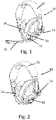
- Fig. 1 schematically illustrates a headset 10 having a first 12 and a second 14 earcup.
- the two earcups 12,14 are configured to be placed over the ears of a wearer.
- the first 12 and the second 14 earcup are connected by a headband 16.
- the headband 16 may be adjustable, e.g., via a slide configured to lengthen or shorten the headband 16, at least the headband 16 is, somewhat, flexible so as to allow a comfortable fit to the user's head. Other adjustment mechanisms may be employed.
- the earcups 12, 14 comprise a pad to provide both a comfortable interface to the user's skin and to provide an at least partial, passive, dampening of sound from the environment of the user.
- the first earcup 12 comprises a recess 18, visible in Fig. 2 , which is configured to connected to a connected part of an arm 20.
- Fig. 2 the headset 10 with an attached arm 20 is illustrated.
- the headset 10 with an attached arm 20 is illustrated.
- the second earcup 14, opposite the first earcup 12 may be omitted.
- the shape and/or size of the earcup or earcups may be varied other than what is illustrated.
- the first earcup 12 further comprises a slide switch 32 and a button 34.
- the button 34 provides an interface for the user to e.g. initiate Bluetooth pairing, and/or other functions, such as changing between sound programs/settings.
- the slide switch 32 provides an interface for the user to change between active noise cancellation settings, e.g., off and on, or between levels or degrees of active noise cancellation.
- An electrical interface in the form of a plug is provided. This interface allows the user/wearer to recharge a battery in the headset 10 so that the headset may operate wirelessly.
- the electrical interface may also be used to provide a wired interface to e.g. a computer for providing a signal representing sound to be played in the headset and/or a signal representing speech to be transmitted out of the headset 10 to a computer.
- the recess 18 comprises an electrical socket and the arm 20 comprises a corresponding plug 22, illustrated in Fig, 4 .
- the socket/recess 18 and plug 22 may be or comprise a USB-type connection, such as a mini-USB, USB-C or other USB type connection.
- electrical connection is established via a set of pogo pins, 24, 26, 28.
- the contacts i.e. here the pogo pins 24, 26 and 28, are placed on a raised part which is shaped to mate with a receptacle formed in the outer surface of the earcup.
- the raised part constitutes a mechanical interface as discussed below.
- Fig. 4 schematically illustrates a detachable boom arm 20 for a headset 10.
- the arm 20 comprises one microphone 30 arranged at a distal end of the arm 20, i.e., remote from the plug part 22.
- the arm 20 is shaped so that the microphone 30 is placed near the mouth of the wearer when the arm 20 is arranged substantially vertical or below. A lower position would also reduce noise induced by the wearer exhaling which still being able to pick up sound in a favorable position.
- the microphone is positioned behind five grooves or slits.
- the headset 10 When the arm 20 is connected to the headset, the headset 10 is configured to operate in different modes based on the orientation of the arm relative to the first earcup 12. This could allow the arm to be positioned in at least two positions during use, e.g. an active state or position where the arm is arranged generally so that one or more microphones are able to pick up sound from the user's mouth, and a mute state where, owing to the position of the arm, signals from at least the one or more microphones in the arm is muted so that privacy of the user is ensured.
- an active state or position where the arm is arranged generally so that one or more microphones are able to pick up sound from the user's mouth
- a mute state where, owing to the position of the arm, signals from at least the one or more microphones in the arm is muted so that privacy of the user is ensured.
- a range of mechanic stops may be provided in a rotation arrangement in an earcup of a headset. This could provide a differentiation between functions in the headset.
- One stop could be around -40 degree relative to horizontal, in which position the arm would provide a microphone signal to a processor in the headset.
- a limit switch is arranged so that the limit switch will be activated when the boom arm 20 is in position about 70 degrees, in which position the limit switch will touch a protrusion so that the microphone mute function is activated.
- a metal spring will abut at another point, and a rib will produce a sound to provide a tactile feedback to the user, and thus provide a better feel for the user, altering or informing the user that the microphone, or microphones, is muted. Similar feedback to the user is provided when the arm 20 is moved in the reverse direction and passes the about 70 degree position.
- Fig. 2 schematically illustrates the headset 10 with a recess 18 for receiving the detachable boom arm 20.
- the headset 10 is configured to operate in a mode where the headset 10 provides a signal based on an output signal from a microphone in the first earcup 12.
- This signal should mainly comprise the wearer's voice.
- Such a signal is then provided via a wireless, or wired, connection to an external device.
- the external device may be a computer device, a mobile phone or the like.
- the recess is here overall rectangular shaped. Further, at one end a first structural feature is provided, and at the opposite, second end of the recess, a second structural feature is provided. The first and second structural features are different.
- the overall oblong shape of the recess also provides an improved rotational properties to the arm/headset interface. The user is able to rotate the arm into different positions so as to achieve different modes of operation.
- Fig. 3 schematically illustrates the headset 10 with a cover plate mounted 36.
- the cover plate 36 provides protection of the recess 18 from dust and/or other debris.
- the cover plate 36 is intended to be placed over the recess 18 when the user detach the arm 20.
- the user could wish to detach the arm 20 when the user wishes to use the headset 10 when walking or being outside his/her house, but not needing the arm 20.
- the headset 10 without the arm 20 could be considered less obtrusive by the user, and, detaching the arm 20 from the headset could be done while the user, e.g., is engaged in a game on a handheld device, such as a smartphone or the like.
- the headset 10 would then be able to transition between operation modes without the user loosing connection to the device.
- the user could be engaged in a conversation via a softphone application on a smartphone while being at the office but needs to leave the office while maintaining the connection to the call.
- the headset 10 detect the configuration change and automatically switch to a mode where a microphone in the headset is used to provide a signal representing the user's voice to the far end of the call.
- the headset 10 could be configured to automatically switch to a mode where at least the microphone 30 in the arm 20 is used to provide a signal comprising the user's voice.
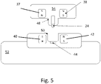
- Fig. 5 schematically illustrates a conceptual interface between a detachable boom arm 20 and a headset 10 in a cross-sectional view.
- a section 54 thereof is configured to attach to a section or part of the earcup as discussed above.
- the section 54 comprises first 37 and second 38 magnets. These are arranged symmetrically at a mechanical interface 48. As shown here, the first and second magnets 37, 38 are arranged with opposite polarities.
- a second mechanical interface 50 is provided in the arm 52.
- the second mechanical interface 50 is configured to mate with the first mechanical interface 48 of the arm 20.
- third 40 and fourth 42 magnets are arranged symmetrically at the second mechanical interface 50.
- the third magnet 40 is arranged so that the polarity match with the polarity of the first magnet 37
- the fourth magnet 42 is arranged so that the polarity match with the second magnet 38. This arrangement is contemplated to allow the arm 20 to be held in place while providing a sufficient retention force which allow the user to manipulate the arm 20 as discussed above regarding rotation of the arm 20 without the arm 20 unintentionally being detached from the earcup of the headset.
- a pogo pin 46 in the arm 20 provides an electrical connection to a contact pad 44 in the earcup.
- the headset is configured to detect if the arm is attached or not. The headset is then configured to modify the operation of the headset dependent on the arm being attached or not.
Landscapes
- Engineering & Computer Science (AREA)
- Physics & Mathematics (AREA)
- Acoustics & Sound (AREA)
- Signal Processing (AREA)
- Manufacturing & Machinery (AREA)
- Health & Medical Sciences (AREA)
- Otolaryngology (AREA)
- Headphones And Earphones (AREA)
- Telephone Set Structure (AREA)
Applications Claiming Priority (1)
| Application Number | Priority Date | Filing Date | Title |
|---|---|---|---|
| EP21182883 | 2021-06-30 |
Publications (2)
| Publication Number | Publication Date |
|---|---|
| EP4114035A2 true EP4114035A2 (fr) | 2023-01-04 |
| EP4114035A3 EP4114035A3 (fr) | 2023-03-22 |
Family
ID=76730426
Family Applications (1)
| Application Number | Title | Priority Date | Filing Date |
|---|---|---|---|
| EP22181743.0A Pending EP4114035A3 (fr) | 2021-06-30 | 2022-06-29 | Casque doté d'un bras détachable |
Country Status (3)
| Country | Link |
|---|---|
| US (1) | US20230007382A1 (fr) |
| EP (1) | EP4114035A3 (fr) |
| CN (1) | CN115550779A (fr) |
Family Cites Families (2)
| Publication number | Priority date | Publication date | Assignee | Title |
|---|---|---|---|---|
| CN203896488U (zh) * | 2014-06-06 | 2014-10-22 | 青岛歌尔声学科技有限公司 | 一种耳机装置 |
| EP3588973B1 (fr) * | 2018-06-21 | 2023-06-21 | Savox Communications Oy AB (LTD) | Casque d'écoute pour casque |
-
2022
- 2022-06-29 US US17/853,157 patent/US20230007382A1/en active Pending
- 2022-06-29 EP EP22181743.0A patent/EP4114035A3/fr active Pending
- 2022-06-30 CN CN202210771595.5A patent/CN115550779A/zh active Pending
Also Published As
| Publication number | Publication date |
|---|---|
| US20230007382A1 (en) | 2023-01-05 |
| EP4114035A3 (fr) | 2023-03-22 |
| CN115550779A (zh) | 2022-12-30 |
Similar Documents
| Publication | Publication Date | Title |
|---|---|---|
| JP6706766B2 (ja) | 音声入出力装置および骨伝導ヘッドセットシステム | |
| US9491534B2 (en) | Monaural wireless headset | |
| US8014553B2 (en) | Ear-mounted transducer and ear-device | |
| EP2320674B1 (fr) | Casque de protection auriculaire pour transmission bidirectionell | |
| EP2840807A1 (fr) | Réseau de microphone externe et prothèse auditive utilisant celui-ci | |
| US9455677B2 (en) | Wireless audio control apparatus | |
| US20070154052A1 (en) | Noise cancelling cable assembly | |
| JP2010147982A (ja) | リモコン付きステレオイヤホンマイク | |
| US10748522B2 (en) | In-ear microphone with active noise control | |
| US10582291B2 (en) | Wireless hearing device | |
| WO2000072628A1 (fr) | Emetteur-recepteur comportant un haut-parleur a conduction osseuse | |
| EP1371261A2 (fr) | Casque audio | |
| EP4114035A2 (fr) | Casque doté d'un bras détachable | |
| US11523209B1 (en) | Method and system for headset with wireless auxiliary device | |
| EP3041257A1 (fr) | Casque d'écoute sans fil monophonique avec capteur tactile | |
| CN115004717B (zh) | 具有更高抗风噪性能的无线耳麦 | |
| KR101847070B1 (ko) | 신체활용형 스마트 통화장치 | |
| KR20100119470A (ko) | 감시기능과 이어폰 겸용 귓속형 마이크를 가지는 무선 헤드셋 장치 | |
| JPH02288455A (ja) | 会議用通話装置 | |
| US20230403494A1 (en) | Earphone and acoustic control method | |
| EP4362499A1 (fr) | Prothèse auditive avec suspension améliorée | |
| JP2023181809A (ja) | イヤフォン、音響制御方法およびプログラム | |
| JPS6327484Y2 (fr) | ||
| KR200315112Y1 (ko) | 복합 무선 이어 마이크 | |
| JP2009239551A (ja) | ワイヤレス通信システム及びワイヤレス通信システムの制御装置 |
Legal Events
| Date | Code | Title | Description |
|---|---|---|---|
| PUAI | Public reference made under article 153(3) epc to a published international application that has entered the european phase |
Free format text: ORIGINAL CODE: 0009012 |
|
| STAA | Information on the status of an ep patent application or granted ep patent |
Free format text: STATUS: THE APPLICATION HAS BEEN PUBLISHED |
|
| AK | Designated contracting states |
Kind code of ref document: A2 Designated state(s): AL AT BE BG CH CY CZ DE DK EE ES FI FR GB GR HR HU IE IS IT LI LT LU LV MC MK MT NL NO PL PT RO RS SE SI SK SM TR |
|
| PUAL | Search report despatched |
Free format text: ORIGINAL CODE: 0009013 |
|
| AK | Designated contracting states |
Kind code of ref document: A3 Designated state(s): AL AT BE BG CH CY CZ DE DK EE ES FI FR GB GR HR HU IE IS IT LI LT LU LV MC MK MT NL NO PL PT RO RS SE SI SK SM TR |
|
| RIC1 | Information provided on ipc code assigned before grant |
Ipc: H04R 1/32 20060101ALI20230213BHEP Ipc: H04R 1/10 20060101ALI20230213BHEP Ipc: H04R 5/033 20060101AFI20230213BHEP |
|
| STAA | Information on the status of an ep patent application or granted ep patent |
Free format text: STATUS: REQUEST FOR EXAMINATION WAS MADE |
|
| 17P | Request for examination filed |
Effective date: 20230922 |
|
| RBV | Designated contracting states (corrected) |
Designated state(s): AL AT BE BG CH CY CZ DE DK EE ES FI FR GB GR HR HU IE IS IT LI LT LU LV MC MK MT NL NO PL PT RO RS SE SI SK SM TR |