EP4113596A1 - Heat dissipation member - Google Patents
Heat dissipation member Download PDFInfo
- Publication number
- EP4113596A1 EP4113596A1 EP21760143.4A EP21760143A EP4113596A1 EP 4113596 A1 EP4113596 A1 EP 4113596A1 EP 21760143 A EP21760143 A EP 21760143A EP 4113596 A1 EP4113596 A1 EP 4113596A1
- Authority
- EP
- European Patent Office
- Prior art keywords
- heat dissipation
- holes
- intermediate member
- hole
- dissipation member
- Prior art date
- Legal status (The legal status is an assumption and is not a legal conclusion. Google has not performed a legal analysis and makes no representation as to the accuracy of the status listed.)
- Pending
Links
Images






Classifications
-
- F—MECHANICAL ENGINEERING; LIGHTING; HEATING; WEAPONS; BLASTING
- F28—HEAT EXCHANGE IN GENERAL
- F28D—HEAT-EXCHANGE APPARATUS, NOT PROVIDED FOR IN ANOTHER SUBCLASS, IN WHICH THE HEAT-EXCHANGE MEDIA DO NOT COME INTO DIRECT CONTACT
- F28D15/00—Heat-exchange apparatus with the intermediate heat-transfer medium in closed tubes passing into or through the conduit walls ; Heat-exchange apparatus employing intermediate heat-transfer medium or bodies
- F28D15/02—Heat-exchange apparatus with the intermediate heat-transfer medium in closed tubes passing into or through the conduit walls ; Heat-exchange apparatus employing intermediate heat-transfer medium or bodies in which the medium condenses and evaporates, e.g. heat pipes
- F28D15/0233—Heat-exchange apparatus with the intermediate heat-transfer medium in closed tubes passing into or through the conduit walls ; Heat-exchange apparatus employing intermediate heat-transfer medium or bodies in which the medium condenses and evaporates, e.g. heat pipes the conduits having a particular shape, e.g. non-circular cross-section, annular
-
- F—MECHANICAL ENGINEERING; LIGHTING; HEATING; WEAPONS; BLASTING
- F28—HEAT EXCHANGE IN GENERAL
- F28D—HEAT-EXCHANGE APPARATUS, NOT PROVIDED FOR IN ANOTHER SUBCLASS, IN WHICH THE HEAT-EXCHANGE MEDIA DO NOT COME INTO DIRECT CONTACT
- F28D15/00—Heat-exchange apparatus with the intermediate heat-transfer medium in closed tubes passing into or through the conduit walls ; Heat-exchange apparatus employing intermediate heat-transfer medium or bodies
- F28D15/02—Heat-exchange apparatus with the intermediate heat-transfer medium in closed tubes passing into or through the conduit walls ; Heat-exchange apparatus employing intermediate heat-transfer medium or bodies in which the medium condenses and evaporates, e.g. heat pipes
- F28D15/04—Heat-exchange apparatus with the intermediate heat-transfer medium in closed tubes passing into or through the conduit walls ; Heat-exchange apparatus employing intermediate heat-transfer medium or bodies in which the medium condenses and evaporates, e.g. heat pipes with tubes having a capillary structure
-
- F—MECHANICAL ENGINEERING; LIGHTING; HEATING; WEAPONS; BLASTING
- F28—HEAT EXCHANGE IN GENERAL
- F28D—HEAT-EXCHANGE APPARATUS, NOT PROVIDED FOR IN ANOTHER SUBCLASS, IN WHICH THE HEAT-EXCHANGE MEDIA DO NOT COME INTO DIRECT CONTACT
- F28D15/00—Heat-exchange apparatus with the intermediate heat-transfer medium in closed tubes passing into or through the conduit walls ; Heat-exchange apparatus employing intermediate heat-transfer medium or bodies
- F28D15/02—Heat-exchange apparatus with the intermediate heat-transfer medium in closed tubes passing into or through the conduit walls ; Heat-exchange apparatus employing intermediate heat-transfer medium or bodies in which the medium condenses and evaporates, e.g. heat pipes
- F28D15/04—Heat-exchange apparatus with the intermediate heat-transfer medium in closed tubes passing into or through the conduit walls ; Heat-exchange apparatus employing intermediate heat-transfer medium or bodies in which the medium condenses and evaporates, e.g. heat pipes with tubes having a capillary structure
- F28D15/046—Heat-exchange apparatus with the intermediate heat-transfer medium in closed tubes passing into or through the conduit walls ; Heat-exchange apparatus employing intermediate heat-transfer medium or bodies in which the medium condenses and evaporates, e.g. heat pipes with tubes having a capillary structure characterised by the material or the construction of the capillary structure
-
- H—ELECTRICITY
- H05—ELECTRIC TECHNIQUES NOT OTHERWISE PROVIDED FOR
- H05K—PRINTED CIRCUITS; CASINGS OR CONSTRUCTIONAL DETAILS OF ELECTRIC APPARATUS; MANUFACTURE OF ASSEMBLAGES OF ELECTRICAL COMPONENTS
- H05K7/00—Constructional details common to different types of electric apparatus
- H05K7/20—Modifications to facilitate cooling, ventilating, or heating
-
- H—ELECTRICITY
- H10—SEMICONDUCTOR DEVICES; ELECTRIC SOLID-STATE DEVICES NOT OTHERWISE PROVIDED FOR
- H10W—GENERIC PACKAGES, INTERCONNECTIONS, CONNECTORS OR OTHER CONSTRUCTIONAL DETAILS OF DEVICES COVERED BY CLASS H10
- H10W40/00—Arrangements for thermal protection or thermal control
- H10W40/70—Fillings or auxiliary members in containers or in encapsulations for thermal protection or control
- H10W40/73—Fillings or auxiliary members in containers or in encapsulations for thermal protection or control for cooling by change of state
Definitions
- the present disclosure relates to a heat dissipation member.
- a known heat dissipation member transfers heat from a high-temperature part to a low-temperature part by utilizing a cycle of evaporation and condensation of a working liquid.
- Patent Document 1 discloses a metal heat pipe in which a plate-shaped intermediate member is interposed between a plate-shaped upper member and a plate-shaped lower member. Lattice-shaped grooves are formed on each of the lower surface of the upper member and the upper surface of the lower member. A plurality of vapor holes extending radially and a plurality of fine through holes generating capillary force are formed in the intermediate member.
- the vapor holes communicate with respective recessed portions of the upper member and the lower member to form a vapor diffusion channel for diffusing the vapor of the working liquid in a plane direction.
- Through holes communicate with each of the recessed portions of the upper member and the lower member, thereby forming a fine capillary channel for returning the working liquid in a direction orthogonal to the plane direction.
- Patent Document 2 discloses a heat pipe made of a ceramic.
- a heat dissipation member includes a plate-shaped intermediate member, a first member and a second member, made of a ceramic.
- the intermediate member includes a plurality of through holes each penetrating through the first surface and the second surface located opposite to each other.
- the first member includes a first groove portion on a third surface facing the first surface of the intermediate member.
- the second member includes a plurality of second groove portions on a fourth surface facing the second surface of the intermediate member, and a heat source is arranged on a fifth surface located opposite to the fourth surface.
- Each of the plurality of through holes decreases in diameter from the first surface side toward the second surface side.
- an X-axis direction, a Y-axis direction, and a Z-axis direction that are orthogonal to each other may be defined to illustrate a rectangular coordinate system in which the Z-axis positive direction is the vertically upward direction.
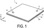
- FIG. 1 is a perspective view of a heat dissipation member according to an embodiment.
- a heat dissipation member 1 includes a first member 10, a second member 20, and an intermediate member 30.
- the first member 10, the second member 20, and the intermediate member 30 are all plate-shaped, and are layered such that the intermediate member 30 is sandwiched between the first member 10 and the second member 20.
- the heat dissipation member 1 includes an internal space in which a working liquid is sealed.
- a working liquid for example, water, a hydrocarbon-based compound, an organic liquid such as ethanol or methanol, or a liquid such as ammonia may be used.
- the first member 10 includes a working liquid injection hole 14 and a gas discharge hole 15.
- the working liquid is injected from the working liquid injection hole 14 into the internal space of the heat dissipation member 1.
- the gas existing in the internal space of the first member 10 is discharged from the gas discharge hole 15 to the outside.
- the working liquid injection hole 14 is located near one of the four corners of the first member 10, and the gas discharge hole 15 is located near another corner located diagonally opposite the working liquid injection hole 14.
- the working liquid injection hole 14 and the gas discharge hole 15 are blocked by sealing members 4 and 5, respectively.
- the working liquid injection hole 14 and the gas discharge hole 15 are blocked, so that the internal space of the heat dissipation member 1 is closed and the working liquid is sealed in the internal space. This can withstand, for example, an increase in internal pressure during a high-temperature load, and enhance thermal diffusivity.
- a ceramic of the same material as the first member 10, the second member 20 and the intermediate member 30 can be used for the sealing members 4 and 5, for example.
- a ceramic of a different material from the first member 10, the second member 20 and the intermediate member 30 can be used for the sealing members 4 and 5, for example.
- the sealing members 4 and 5 are not limited to a ceramic but may be a metal, a resin or the like.
- a respective adhesive may be interposed between the working liquid injection hole 14 and the sealing member 4, and between the gas discharge hole 15 and the sealing member 5.
- the adhesive may be, for example, a resin such as silicone or polyimide.
- the working liquid is filled, for example, at a ratio of 10 vol% to 95 vol% with respect to the total volume of the internal space of the operating region 100.
- the ratio is 30 vol% to 75 vol%. More preferably, the ratio is 40 vol% to 65 vol%.
- the remaining portion of the internal space of the heat dissipation member 1 other than the working liquid is in a vacuum state including some of the vaporized working liquid.
- the first member 10, the second member 20 and the intermediate member 30 are made of a ceramic.
- the ceramic constituting the first member 10, the second member 20 and the intermediate member 30 for example, alumina (Al 2 O 3 ), zirconia (ZrO 2 ), silicon carbide (SiC), silicon nitride (Si 3 N 4 ), aluminum nitride (A1N), cordierite (Mg 2 Al 3 (AlSi 5 O 18 )), silicon impregnated silicon carbide (SiSiC) or the like, can be used.
- the ceramic constituting the first member 10, the second member 20 and the intermediate member 30 may be a single crystal.
- the metal heat dissipation member 1 has room for improvement in corrosion resistance because the part in contact with the working liquid is metal.
- the heat dissipation member 1 since the first member 10, the second member 20, and the intermediate member 30, are all made of a ceramic, the heat dissipation member 1 can be made thinner and has excellent corrosion resistance as compared with a heat dissipation member made of a metal.
- the heat dissipation member 1 is installed with the first member 10 facing upward, but the installation state of the heat dissipation member 1 is not limited to the example illustrated in FIG. 1 .
- the heat dissipation member 1 may be installed with the first member 10 facing downward.
- the heat dissipation member 1 is not limited to the horizontal arrangement as illustrated in FIG. 1 , but may be arranged vertically.
- FIG. 2 is a view in which a first member 10 according to an embodiment is viewed from the Z-axis negative direction side toward the Z-axis positive direction.
- FIG. 2 illustrates a lower surface of the first member 10, specifically, a surface (third surface) facing the upper surface (first surface) of the intermediate member 30.
- the first member 10 includes a lattice-shaped first groove portion 11 on the third surface.
- the first groove portion 11 includes a first recessed portion 11a recessed with respect to the third surface and a plurality of first protruding portions 11b located within the first recessed portion 11a.
- the first recessed portion 11a is located at the center portion of the third surface, and its outline in plan view is, for example, a square.
- the plurality of first protruding portions 11b are arranged longitudinally (Y-axis direction) and laterally (X-axis direction) at intervals from each other within the first recessed portion 11a.
- the first recessed portion 11a and the plurality of first protruding portions 11b make the first groove portion 11 have a lattice shape.
- an area where the first groove portion 11 is located on the third surface of the first member 10, will be referred to as a "groove forming region 100".
- the working liquid injection hole 14 and the gas discharge hole 15 are located in the groove forming region 100.
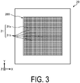
- FIG. 3 is a view in which the second member 20 according to an embodiment is viewed from the Z-axis positive direction side toward the Z-axis negative direction.
- FIG. 3 illustrates the upper surface of the second member 20, specifically, the surface (the fourth surface) facing the lower surface (the second surface) of the intermediate member 30.
- the second member 20 includes a lattice-shaped second groove portion 21 on the fourth surface.
- the second groove portion 21 includes a second recessed portion 21a recessed with respect to the fourth surface and a plurality of second protruding portions 21b located within the second recessed portion 21a.
- the second recessed portion 21a is located at the center portion of the fourth surface, and its outline in plan view is, for example, a square.
- the plurality of second protruding portions 21b are arranged longitudinally (Y-axis direction) and laterally (X-axis direction) at intervals from each other within the second recessed portion 21a.
- the second recessed portion 21a and the plurality of second protruding portions 21b make the second groove portion 21 have a lattice shape.
- groove forming region 200 an area where the second groove portion 21 is located on the fourth surface of the second member 20 will be referred to as a "groove forming region 200".
- the size of the groove forming region 200 in the second member 20 is the same as the size of the groove forming region 100 in the first member 10.
- the position of the groove forming region 200 on the fourth surface of the second member 20 is the same as the position of the groove forming region 100 on the third surface of the first member 10.
- a heat source is arranged on the lower surface (fifth surface) located opposite to the upper surface (fourth surface) of the second member 20.
- each of the first groove portion 11 and the second groove portion 21 in a lattice shape, the working liquid can be efficiently circulated in the internal space of the heat dissipation member 1.
- each of the first groove portion 11 and the second groove portion 21 need not necessarily have a lattice shape.
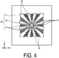
- FIG. 4 is a view in which an intermediate member 30 according to an embodiment is viewed from the Z-axis positive direction side toward the Z-axis negative direction.
- the intermediate member 30 includes: an edge portion 31 having a rectangular frame shape; a center portion 32 having a circular shape in plan view located inside the edge portion 31; and a plurality of connecting portions 33 located between the center portion 32 and the edge portion 31 and connecting the center portion 32 and the edge portion 31.
- the center portion 32 is located at the center of intermediate member 30.
- the plurality of connecting portions 33 extend radially, widening from the center portion 32 toward the edge portion 31, at intervals from each other.
- the intermediate member 30 further includes a plurality of vapor holes 35 and a plurality of through holes 37.
- Each of the plurality of vapor holes 35 and each of the plurality of through holes 37 penetrate the upper surface (first surface) and the lower surface (second surface) of the intermediate member 30.
- the plurality of vapor holes 35 function as a part of a channel for the vapor of the working liquid.
- Each of the plurality of vapor holes 35 is located between two adjacent connecting portions 33. That is, each of the plurality of vapor holes 35 and each of the plurality of connecting portions 33 are alternately located in the circumferential direction.
- the plurality of vapor holes 35 like the plurality of connecting portions 33, extend radially, widening from the center portion 32 toward the edge portion 31 at intervals from each other.
- the plurality of through holes 37 function as a part of a channel for the working liquid.
- Each of the through holes 37 is a fine hole having a smaller opening area than the vapor hole 35 described above. Specifically, the through hole 37 is small enough to cause a capillary phenomenon in the working liquid passing the through hole 37.
- the plurality of through holes 37 are located at the center portion 32 and the plurality of connecting portions 33, of the intermediate member 30.
- FIG. 5 is an enlarged view of the periphery of the center portion 32 in the intermediate member 30.
- the plurality of through holes 37 include a plurality of types (here, three types) of through holes having different opening diameters (in other words, the opening diameter on the first member 10 side), when the intermediate member 30 is viewed from the Z-axis positive direction toward the Z-axis negative direction.
- the three types are a plurality of first through holes 37a, a second through hole 37b and a plurality of third through holes 37c.
- a plurality of first through holes 37a are located at each of the connecting portions 33 of the intermediate member 30.
- the opening diameter of the first through holes 37a as viewed from the first member 10 side is, for example, from 250 ⁇ m to 700 ⁇ m.
- the second through hole 37b is located at the center of the center portion 32 of the intermediate member 30.
- the second through hole 37b has a larger diameter than the first through hole 37a.
- the opening diameter of the second through hole 37b as viewed from the first member 10 side is, for example, from 550 ⁇ m to 900 ⁇ m. Note that a plurality of second through holes 37b may be provided at the center portion 32.
- a plurality of third through holes 37c is located at each of the connecting portions 33 of the intermediate member 30. Specifically, a plurality of third through holes 37c is located in a region within each of the connecting portions 33, near the center portion 32. A plurality of third through holes 37c is also located at the center portion 32 of the intermediate member 30. Specifically, a plurality of third through holes 37c is located on the outer peripheral portion side of the center portion 32, that is, in a region near the connecting portion 33. The third through holes 37c have a smaller diameter than the first through holes 37a. For example, the opening diameter of the third through holes 37c as viewed from the first member 10 side is, for example, from 200 to 400 ⁇ m.
- the plurality of through holes 37 are located in the order of the second through hole 37b having a large opening diameter, the third through holes 37c each having a small opening diameter, and the first through holes 37a each having a medium opening diameter, advancing from the center to the outer periphery of the intermediate member 30.
- the center portion 32 of the intermediate member 30 has a longer distance to each of the vapor holes 35 than the connecting portions 33, the circulating flow of the working liquid tends to stagnate at the center portion 32. That is, the center portion of the heat dissipation member 1 tends to be a heat spot.
- the heat dissipation member 1 according to the embodiment by providing the center portion 32 of the intermediate member 30 with the second through hole 37b having a large opening diameter, the vapor generated at the center portion 32 can be moved from the second through hole 37b to the low-temperature side.
- the circulating flow of the working liquid at the center portion of the heat dissipation member 1 can be promoted. Accordingly, the center portion of the heat dissipation member 1 can be suppressed from becoming a heat spot.
- the density of the through holes 37 at the center portion 32 of the intermediate member 30 is smaller than the density of the through holes 37 at the connecting portions 33 of the intermediate member 30.
- the ratio of the opening area of the through holes 37 (the second through hole 37b and the plurality of third through holes 37c) to the area of the center portion 32 is smaller than the ratio of the opening area of the through holes 37 (the plurality of first through holes 37a and the plurality of third through holes 37c) to the area of the connecting portions 33.
- FIG. 6 is a diagram in which a groove forming region 100 illustrated in FIG. 2 and a groove forming region 200 illustrated in FIG. 3 are superimposed on the intermediate member 30 illustrated in FIG. 4 .
- the groove forming regions 100 and 200 formed respectively on the first member 10 and the second member 20 overlap the edge portion 31 of the intermediate member 30. That is, the groove forming regions 100 and 200 each spread outward from the region (hereinafter referred to as "hole forming region") where the plurality of vapor holes 35 and the plurality of through holes 37 are formed in the intermediate member 30.
- the internal space of the heat dissipation member 1 can be spread outward as compared with the case where the groove forming regions 100 and 200 are each made equal to the hole forming region.
- the heat source is arranged at the center portion of the heat dissipation member 1, and the temperature of the heat dissipation member 1 becomes lower with increasing distance from the heat source, that is, approaching the outer peripheral portion of the heat dissipation member 1.
- the vapor of the working liquid condenses into a liquid upon moving to a low-temperature region. Accordingly, by spreading the internal space of the heat dissipation member 1 outward, condensation of the working liquid is more likely to occur. This makes it difficult for dry out to occur.
- first groove forming region 110 and the second groove forming region 120 spread outward from the hole forming region of the intermediate member 30 are illustrated; however, the configuration is not limited to this, the hole forming region of the intermediate member 30 may spread outward from the first groove forming region 110 and the second groove forming region 120.
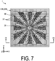
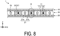
- FIGs. 7 and 8 are diagrams illustrating the flow of the working liquid in the heat dissipation member 1 according to the embodiment.
- FIG. 7 is a diagram in which the edge portion 31 is omitted from the view illustrated in FIG. 6
- FIG. 8 is a cross-sectional diagram taken along an IX-IX arrow in FIG. 7 .
- the vapor flow is indicated by a hollow arrow and the liquid flow is indicated by a black arrow.
- the working liquid is vaporized into a vapor by being heated by a heat source.
- the heat source is located at the center portion of the lower surface (fifth surface) of the second member 20 (see FIGs. 1 and 3 ).
- the vapor of the working liquid is generated at the center portion of the high-temperature side space (space sandwiched between the second member 20 and the intermediate member 30) where the heat source is arranged.
- the vapor of the working liquid is diffused (see the hollow arrow illustrated in FIG. 7 ) in the in-plane direction (XY plane direction) of the heat dissipation member 1 through the groove forming region 200 (second groove portion 21), and moves (see the white arrow illustrated in FIG. 8 ) to the upper low-temperature-side space (space between the first member 10 and the intermediate member 30) through the plurality of vapor holes 35.
- the vapor that has moved to the low-temperature-side space condenses into a liquid as the temperature decreases.
- the liquefied working liquid moves (see the black arrow illustrated in FIG. 7 ) in the groove forming region 100 (first groove portion 11) toward the center portion of the heat dissipation member 1, by the capillary force of the groove forming region 100.
- the working liquid enters the through holes 37 and is returned to the high-temperature-side space by the capillary force of the through holes 37 (see the black arrow in FIG. 8 ).
- the heat dissipation member 1 can transfer heat from the heat source.
- FIG. 9 is an enlarged view of the H portion illustrated in FIG. 8 .
- the through hole 37 decreases in diameter from an upper surface 301 (the first surface) side, which is a low-temperature-side surface of the plate surfaces of the intermediate member 30, toward the lower surface 302 (the second surface) side, which is a high-temperature-side surface.
- the opening diameter of the through hole 37 narrows from the low-temperature side to the high-temperature side.
- the working liquid can easily enter the through hole 37.
- the magnitude of the capillary force in the through hole 37 can be increased toward the high-temperature side.
- the working liquid entering the through hole 37 from the low-temperature side can be pulled to the high-temperature side at an accelerated rate by the capillary force gradually increasing.
- the heat dissipation member 1 by forming the through hole 37 in a tapered shape, allows the circulation efficiency of the working liquid to be enhanced.
- the second through hole 37b (see FIG. 5 ) among the plurality of through holes 37 is also used as a channel for vapor.
- the second through hole 37b may be formed in a straight shape with a constant opening diameter configured to facilitate movement of the vapor.
- the surface roughness of an inner surface 371 of the through hole 37 is larger than that of the upper surface 301 (the first surface) of the intermediate member 30.
- the working liquid is more likely to enter the through hole 37 having a larger surface roughness.
- the circulation efficiency of the working liquid can be enhanced.
- the surface roughness of the inner surface 211 of the second groove portion 21 is larger than that of the inner surface 371 of the through hole 37. Thus, the working liquid is easily discharged from the inside of the through hole 37 to the second groove portion 21.
- respective green sheets are formed by a doctor blade method or a roll compaction method using respective materials of the first member 10, the second member 20 and the intermediate member 30. Then, by layering a plurality of the respective green sheets, a laminate is obtained.
- the obtained laminate is subjected to laser beam machining or die punching, thereby obtaining a respective compact of the first member 10, the second member 20 and the intermediate member 30.
- a compact of the intermediate member 30 having therein a plurality of vapor holes 35 and a plurality of through holes 37 formed can be obtained, by applying laser beam machining to the laminate.
- the surface roughness of the inner surface 371 of the through hole 37 can be made larger than the surface roughness of the upper surface 301 (the first surface) of the intermediate member 30 by this laser beam machining.
- Respective compacts of the first member 10 and the second member 20 on which the groove forming regions 100 and 200 are formed respectively are obtained by applying laser beam machining to the obtained laminate.
- the surface roughness of the inner surface 211 of the second groove portion 21 can be made larger than the surface roughness of the inner surface 371 of the through hole 37 by adjusting the output of the laser in the laser beam machining.
- the working liquid is injected into the sintered body from the working liquid injection hole 14 provided in the first member 10.
- the gas existing inside the sintered body is discharged to the outside from the gas discharge hole 15 of the first member 10 with the injection of the working liquid.
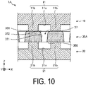
- FIG. 10 is a diagram illustrating the configuration of a through hole according to a first variation. As illustrated in FIG. 10 , the heat dissipation member 1A according to the first variation includes an intermediate member 30A.
- the intermediate member 30A according to the first variation includes a chamfered portion 372 between the upper surface 301 (the first surface) and the through hole 37.
- the chamfered portion 372 includes a curved convex surface connecting, for example, the upper surface 301 (the first surface) and the inner surface 371 of the through hole 37.
- the working liquid can easily enter the through hole 37.
- the chamfered portion 372 is not necessarily curved (R-shaped), but may be planar (C-shaped), for example.
- the output of the laser beam machining or the shape of the die may be adjusted. Thereafter, the obtained compact is fired together with the first member 10 and the second member 20 to obtain a sintered body in which the first member 10, the second member 20 and the intermediate member 30A are integrated.
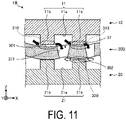
- FIG. 11 is a diagram illustrating the configuration of a through hole according to a second variation. As illustrated in FIG. 11 , the heat dissipation member 1B according to the second variation includes an intermediate member 30B.
- the intermediate member 30B according to the second variation is meandering with respect to the XY plane.
- the heat dissipation member 1B includes a first gap 310 between at least one of a plurality of first protruding portions 11b of the first groove portion 11 and the upper surface 301 of the intermediate member 30B.
- the heat dissipation member 1B enables the working liquid to circulate in not only the first groove portion 11 but also in the first gap 310.
- the working liquid is guided to the through hole 37 by capillary force in the first gap 310 and enters the through hole 37.
- the heat dissipation member 1B enables the circulation efficiency of the working liquid to be further enhanced by including the first gap 310.
- the heat dissipation member 1B includes a second gap 320 between at least one of the plurality of second protruding portions 21b of the second groove portion 21 and the lower surface 302 of the intermediate member 30B.
- the heat dissipation member 1B enables the vapor of the working liquid to circulate in not only the second groove portion 21 but also in the second gap 320.
- the heat dissipation member 1B enables the diffusion of the vapor of the working liquid to accelerate by including the second gap 320. That is, the circulation efficiency of the working liquid can be enhanced.
- the pressure applied to the laminate at the time of layering the green sheets may be adjusted.
- a compact of the intermediate member 30B meandering with respect to the XY plane can be obtained.
- the obtained compact is fired together with the first member 10 and the second member 20 to obtain a sintered body in which the first member 10, the second member 20 and the intermediate member 30B are integrated.
- the surface roughness of the inner surface 211 of the second groove portion 21 is larger than that of the lower surface 302 (second surface) of the intermediate member 30. Thus, the working liquid is easily discharged from the lower surface 302 (second surface) of the intermediate member 30 to the second groove portion 21.
- the circulation efficiency of the working liquid can be enhanced.
- the surface roughness of the upper surface 301 (the first surface) of the intermediate member 30, the inner surface 371 of the through hole 37, the lower surface 302 (the second surface), and the inner surface 211 of the second groove portion 21 may be adjusted within a range in which the arithmetic mean roughness Ra is, for example, from 0.08 ⁇ m to 0.4 ⁇ m, from 0.3 ⁇ m to 0.6 ⁇ m, from 0.08 ⁇ m to 0.4 ⁇ m, and from 0.5 ⁇ m to 0.8 ⁇ m, respectively.
- FIG. 12 is a side view of a heat dissipation member according to a third variation.
- a heat dissipation member 1C may include a conductor 6 on the lower surface (the fifth surface) of the second member 20 that is on the high-temperature side.
- the heat dissipation member 1C made of a ceramic, which is an insulator, an electronic component can be directly mounted thereon by using the conductor 6 as a wiring or an electrode.
- FIG. 13 is a side view of a heat dissipation member according to a fourth variation.
- a heat dissipation member 1D may include a covering layer 7 covering at least a part of the conductor 6 on the lower surface (the fifth surface) of the second member 20 that is on the high-temperature side.
- FIG. 14 is a side view of a heat dissipation member according to a fifth variation.
- a heat dissipation member 1E may include a heat sink 8 on the upper surface (sixth surface) of the first member 10 that is on the low-temperature side.
- the heat sink 8 may be made of a metal or a ceramic.
- the heat sink 8 includes, for example, a plurality of fins 81. Thus, the heat dissipation effect can be further enhanced.
- FIG. 15 is a side view of a heat dissipation member according to a sixth variation.
- the heat dissipation member 1F may include a first member 10F in which a plurality of fins 18 made of a ceramic are integrally formed on the upper surface (the sixth surface) of the first member 10F.
- the first member 10F is obtained, for example, by firing a compact in which a plurality of fins 18 are formed by laser beam machining or die punching on a laminate of green sheets.
- an adhesive or the like for attaching the fin 18 is not required, so that reliability can be improved. Heat dissipation is not hindered by an adhesive or the like.
- Some of the fins 18 are preferably located outside the internal space, of the heat dissipation member IF, formed by the groove forming region 100 of the first member 10F, the groove forming region 200 of the second member 20, and the vapor holes 35 and the through holes 37 of the intermediate member 30.
- the heat dissipation effect can be further enhanced.
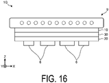
- FIG. 16 is a side view of a heat dissipation member according to a seventh variation.
- a heat dissipation member 1G may include a temperature adjusting plate 9 on the upper surface (sixth surface) of the first member 10 that is on the low-temperature side.
- the temperature adjusting plate 9 may be, for example, water-cooled, air-cooled, or resistance-heated.
- the heat dissipation member (e.g., heat dissipation member 1, 1A to 1G) according to the embodiments includes a plate-shaped intermediate member (e.g., intermediate member 30, 30A, 30B), a first member (e.g., first member 10, 10F) and a second member (e.g., second member 20), made of a ceramic.
- the intermediate member includes a plurality of through holes (e.g., through hole 37) each penetrating through the first surface (e.g., upper surface 301) and the second surface (e.g., lower surface 302), of the intermediate member, located on opposite sides to each other.
- the first member includes a first groove portion (e.g., first groove portion 11) on a third surface (e.g., lower surface) facing the first surface of the intermediate member.
- the second member includes a plurality of second groove portions (e.g., the second groove portion 21) on a fourth surface (e.g., upper surface) facing the second surface of the intermediate member, and a heat source is arranged on a fifth surface (e.g., lower surface) located opposite to the fourth surface.
- the surface roughness of the inner surface of the through hole is larger than that of the first surface.
- the first groove portion and the second groove portion are lattice-shaped.
- the working liquid can be efficiently circulated in the internal space of the heat dissipation member.
- the surface roughness of the inner surface of the second groove portion is larger than that of the inner surface of the through hole. Therefore, the working liquid is easily discharged from the inside of the through hole to the second groove portion, so that the circulation efficiency of the working liquid can be enhanced.
- the first groove portion includes a first recessed portion (e.g., first recessed portion 11a) recessed with respect to the third surface and a plurality of first protruding portions (the first protruding portions 11b) located in the first recessed portion.
- the heat dissipation member according to the embodiment includes a gap (e.g., first gap 310) between at least one of the plurality of first protruding portions and the first surface.
- the second groove portion includes a second recessed portion (e.g., the second recessed portion 21a) recessed with respect to the fourth surface and a plurality of second protruding portions (e.g., the second protruding portions 21b) located in the second recessed portion.
- the heat dissipation member according to the embodiment includes a gap (e.g., second gap 320) between at least one of the plurality of second protruding portions and the second surface.
- the intermediate member includes an edge portion (e.g., edge portion 31), a center portion (e.g., center portion 32), and a plurality of connecting portions (e.g., connecting portions 33) located between the center portion and the edge portion and connecting the center portion and the edge portion.
- the plurality of through holes includes a plurality of first through holes (e.g., first through holes 37a) located at a connecting portion and at least one second through hole (e.g., second through hole 37b) located at a center portion and having an opening area larger than that of the first through hole.
- the first groove portion and the second groove portion overlap the edge portion.
- Each of the plurality of through holes decreases in diameter from the first surface side toward the second surface side.
- the working liquid can easily enter the through hole.
- the magnitude of the capillary force in the through hole can be increased toward the high-temperature side.
- the circulation efficiency of the working liquid can be enhanced. That is, the heat dissipation efficiency can be further improved.
- the intermediate member includes a chamfered portion (e.g., chamfered portion 372) between the first surface and the through hole.
- a chamfered portion e.g., chamfered portion 372
- the shape of the through hole is a shape (tapered shape) in which the through hole decreases in diameter from the first surface side toward the second surface side of the intermediate member
- the shape of the through hole is not limited to a tapered shape.
- the shape of the through hole may be a shape (reverse taper shape) in which the through hole spreads in diameter from the first surface side to the second surface side of the intermediate member.
- the shape of the through hole may be a shape (straight shape) in which the through hole is substantially constant in diameter from the first surface side to the second surface side of the intermediate member.
Landscapes
- Engineering & Computer Science (AREA)
- Physics & Mathematics (AREA)
- Thermal Sciences (AREA)
- Life Sciences & Earth Sciences (AREA)
- Sustainable Development (AREA)
- Mechanical Engineering (AREA)
- General Engineering & Computer Science (AREA)
- Microelectronics & Electronic Packaging (AREA)
- Cooling Or The Like Of Semiconductors Or Solid State Devices (AREA)
- Cooling Or The Like Of Electrical Apparatus (AREA)
Abstract
Description
- The present disclosure relates to a heat dissipation member.
- A known heat dissipation member (heat pipe) transfers heat from a high-temperature part to a low-temperature part by utilizing a cycle of evaporation and condensation of a working liquid.
-
Patent Document 1 discloses a metal heat pipe in which a plate-shaped intermediate member is interposed between a plate-shaped upper member and a plate-shaped lower member. Lattice-shaped grooves are formed on each of the lower surface of the upper member and the upper surface of the lower member. A plurality of vapor holes extending radially and a plurality of fine through holes generating capillary force are formed in the intermediate member. - In the heat pipe described in
Patent Document 1, the vapor holes communicate with respective recessed portions of the upper member and the lower member to form a vapor diffusion channel for diffusing the vapor of the working liquid in a plane direction. Through holes communicate with each of the recessed portions of the upper member and the lower member, thereby forming a fine capillary channel for returning the working liquid in a direction orthogonal to the plane direction. - Patent Document 2 discloses a heat pipe made of a ceramic.
-
- Patent Document 1:
JP 4112602 B - Patent Document 2:
JP 59-173690 A - In an aspect of the present disclosure, a heat dissipation member includes a plate-shaped intermediate member, a first member and a second member, made of a ceramic. The intermediate member includes a plurality of through holes each penetrating through the first surface and the second surface located opposite to each other. The first member includes a first groove portion on a third surface facing the first surface of the intermediate member. The second member includes a plurality of second groove portions on a fourth surface facing the second surface of the intermediate member, and a heat source is arranged on a fifth surface located opposite to the fourth surface. Each of the plurality of through holes decreases in diameter from the first surface side toward the second surface side.
-
-
FIG. 1 is a perspective view of a heat dissipation member according to an embodiment. -
FIG. 2 is a view in which a first member according to an embodiment is viewed from a Z-axis negative direction side toward a Z-axis positive direction. -
FIG. 3 is a view in which a second member according to an embodiment is viewed from a Z-axis positive direction side toward a Z-axis negative direction. -
FIG. 4 is a view in which an intermediate member according to an embodiment is viewed from the Z-axis positive direction side toward the Z-axis negative direction. -
FIG. 5 is an enlarged view of the periphery of the center portion in anintermediate member 30. -
FIG. 6 is a diagram in which a groove forming region illustrated inFIG. 2 and a groove forming region illustrated inFIG. 3 are superimposed on the intermediate member illustrated inFIG. 4 . -
FIG. 7 is a diagram illustrating the flow of a working liquid in a heat dissipation member according to an embodiment. -
FIG. 8 is a diagram illustrating the flow of a working liquid in a heat dissipation member according to an embodiment. -
FIG. 9 is an enlarged view of an H portion illustrated inFIG. 8 . -
FIG. 10 is a diagram illustrating the configuration of a through hole according to a first variation. -
FIG. 11 is a diagram illustrating the configuration of a through hole according to a second variation. -
FIG. 12 is a side view of a heat dissipation member according to a third variation. -
FIG. 13 is a side view of a heat dissipation member according to a fourth variation. -
FIG. 14 is a side view of a heat dissipation member according to a fifth variation. -
FIG. 15 is a side view of a heat dissipation member according to a sixth variation. -
FIG. 16 is a side view of a heat dissipation member according to a seventh variation. - Hereinafter, configurations (hereinafter referred to as "embodiments") for implementing the heat dissipation member according to the present disclosure will be described in detail with reference to the drawings. The present disclosure is not limited by the embodiments. The respective embodiments can be suitably combined to the extent that they do not contradict each other in terms of processing content. Note that, in the following embodiments, the same parts are denoted by the same reference signs, and duplicate descriptions are omitted.
- In the following embodiments, expressions such as "constant", "orthogonal", "vertical" or "parallel" may be used, but these expressions need not be strictly "constant", "orthogonal", "vertical" or "parallel". That is, each of the expressions described above allows for deviations in, for example, manufacturing accuracy, installation accuracy, and the like.
- In each of the drawings referred to below, for ease of explanation, an X-axis direction, a Y-axis direction, and a Z-axis direction that are orthogonal to each other may be defined to illustrate a rectangular coordinate system in which the Z-axis positive direction is the vertically upward direction.
- First, the overall configuration of a heat dissipation member according to an embodiment will be described with reference to
FIG. 1. FIG. 1 is a perspective view of a heat dissipation member according to an embodiment. - As illustrated in
FIG. 1 , aheat dissipation member 1 includes afirst member 10, asecond member 20, and anintermediate member 30. Thefirst member 10, thesecond member 20, and theintermediate member 30 are all plate-shaped, and are layered such that theintermediate member 30 is sandwiched between thefirst member 10 and thesecond member 20. - The
heat dissipation member 1 includes an internal space in which a working liquid is sealed. As the working liquid, for example, water, a hydrocarbon-based compound, an organic liquid such as ethanol or methanol, or a liquid such as ammonia may be used. - The
first member 10 includes a workingliquid injection hole 14 and agas discharge hole 15. The working liquid is injected from the workingliquid injection hole 14 into the internal space of theheat dissipation member 1. As the working liquid is injected, the gas existing in the internal space of thefirst member 10 is discharged from thegas discharge hole 15 to the outside. The workingliquid injection hole 14 is located near one of the four corners of thefirst member 10, and thegas discharge hole 15 is located near another corner located diagonally opposite the workingliquid injection hole 14. - The working
liquid injection hole 14 and thegas discharge hole 15 are blocked by sealingmembers liquid injection hole 14 and thegas discharge hole 15 are blocked, so that the internal space of theheat dissipation member 1 is closed and the working liquid is sealed in the internal space. This can withstand, for example, an increase in internal pressure during a high-temperature load, and enhance thermal diffusivity. - A ceramic of the same material as the
first member 10, thesecond member 20 and theintermediate member 30 can be used for the sealingmembers first member 10, thesecond member 20 and theintermediate member 30 can be used for the sealingmembers members liquid injection hole 14 and the sealingmember 4, and between thegas discharge hole 15 and the sealingmember 5. The adhesive may be, for example, a resin such as silicone or polyimide. - The working liquid is filled, for example, at a ratio of 10 vol% to 95 vol% with respect to the total volume of the internal space of the
operating region 100. Preferably, the ratio is 30 vol% to 75 vol%. More preferably, the ratio is 40 vol% to 65 vol%. The remaining portion of the internal space of theheat dissipation member 1 other than the working liquid is in a vacuum state including some of the vaporized working liquid. Thus, since the vapor-liquid equilibrium can be maintained even under a high-temperature environment, dryout is less prone to occur, and since heat diffusion is efficiently performed even under a low-temperature environment, heat diffusivity can be enhanced in various temperature ranges. - The
first member 10, thesecond member 20 and theintermediate member 30 are made of a ceramic. As the ceramic constituting thefirst member 10, thesecond member 20 and theintermediate member 30, for example, alumina (Al2O3), zirconia (ZrO2), silicon carbide (SiC), silicon nitride (Si3N4), aluminum nitride (A1N), cordierite (Mg2Al3(AlSi5O18)), silicon impregnated silicon carbide (SiSiC) or the like, can be used. The ceramic constituting thefirst member 10, thesecond member 20 and theintermediate member 30 may be a single crystal. - It is difficult to make the metal heat dissipation member rigid due to the material and construction method thereof, and it is difficult to make thin. The metal heat dissipation member has room for improvement in corrosion resistance because the part in contact with the working liquid is metal. On the other hand, in the
heat dissipation member 1 according to an embodiment, since thefirst member 10, thesecond member 20, and theintermediate member 30, are all made of a ceramic, theheat dissipation member 1 can be made thinner and has excellent corrosion resistance as compared with a heat dissipation member made of a metal. - In the example illustrated in
FIG. 1 , theheat dissipation member 1 is installed with thefirst member 10 facing upward, but the installation state of theheat dissipation member 1 is not limited to the example illustrated inFIG. 1 . For example, theheat dissipation member 1 may be installed with thefirst member 10 facing downward. Theheat dissipation member 1 is not limited to the horizontal arrangement as illustrated inFIG. 1 , but may be arranged vertically. - The configuration of the
first member 10 will be described with reference toFIG. 2. FIG. 2 is a view in which afirst member 10 according to an embodiment is viewed from the Z-axis negative direction side toward the Z-axis positive direction. -
FIG. 2 illustrates a lower surface of thefirst member 10, specifically, a surface (third surface) facing the upper surface (first surface) of theintermediate member 30. As illustrated inFIG. 2 , thefirst member 10 includes a lattice-shapedfirst groove portion 11 on the third surface. - The
first groove portion 11 includes a first recessedportion 11a recessed with respect to the third surface and a plurality of first protrudingportions 11b located within the first recessedportion 11a. The first recessedportion 11a is located at the center portion of the third surface, and its outline in plan view is, for example, a square. The plurality of first protrudingportions 11b are arranged longitudinally (Y-axis direction) and laterally (X-axis direction) at intervals from each other within the first recessedportion 11a. The first recessedportion 11a and the plurality of first protrudingportions 11b make thefirst groove portion 11 have a lattice shape. - Hereinafter, an area where the
first groove portion 11 is located on the third surface of thefirst member 10, will be referred to as a "groove forming region 100". The workingliquid injection hole 14 and thegas discharge hole 15 are located in thegroove forming region 100. - The configuration of the
second member 20 will be described with reference toFIG. 3. FIG. 3 is a view in which thesecond member 20 according to an embodiment is viewed from the Z-axis positive direction side toward the Z-axis negative direction. -
FIG. 3 illustrates the upper surface of thesecond member 20, specifically, the surface (the fourth surface) facing the lower surface (the second surface) of theintermediate member 30. As illustrated inFIG. 3 , thesecond member 20 includes a lattice-shapedsecond groove portion 21 on the fourth surface. - The
second groove portion 21 includes a second recessedportion 21a recessed with respect to the fourth surface and a plurality of second protrudingportions 21b located within the second recessedportion 21a. The second recessedportion 21a is located at the center portion of the fourth surface, and its outline in plan view is, for example, a square. The plurality of second protrudingportions 21b are arranged longitudinally (Y-axis direction) and laterally (X-axis direction) at intervals from each other within the second recessedportion 21a. The second recessedportion 21a and the plurality of second protrudingportions 21b make thesecond groove portion 21 have a lattice shape. - Hereinafter, an area where the
second groove portion 21 is located on the fourth surface of thesecond member 20 will be referred to as a "groove forming region 200". - The size of the
groove forming region 200 in thesecond member 20 is the same as the size of thegroove forming region 100 in thefirst member 10. The position of thegroove forming region 200 on the fourth surface of thesecond member 20 is the same as the position of thegroove forming region 100 on the third surface of thefirst member 10. - A heat source is arranged on the lower surface (fifth surface) located opposite to the upper surface (fourth surface) of the
second member 20. - Thus, by forming each of the
first groove portion 11 and thesecond groove portion 21 in a lattice shape, the working liquid can be efficiently circulated in the internal space of theheat dissipation member 1. Note that each of thefirst groove portion 11 and thesecond groove portion 21 need not necessarily have a lattice shape. - The configuration of the
intermediate member 30 will be described with reference toFIG. 4. FIG. 4 is a view in which anintermediate member 30 according to an embodiment is viewed from the Z-axis positive direction side toward the Z-axis negative direction. - As illustrated in
FIG. 4 , theintermediate member 30 includes: anedge portion 31 having a rectangular frame shape; acenter portion 32 having a circular shape in plan view located inside theedge portion 31; and a plurality of connectingportions 33 located between thecenter portion 32 and theedge portion 31 and connecting thecenter portion 32 and theedge portion 31. In the example illustrated inFIG. 4 , thecenter portion 32 is located at the center ofintermediate member 30. The plurality of connectingportions 33 extend radially, widening from thecenter portion 32 toward theedge portion 31, at intervals from each other. - The
intermediate member 30 further includes a plurality of vapor holes 35 and a plurality of throughholes 37. Each of the plurality of vapor holes 35 and each of the plurality of throughholes 37 penetrate the upper surface (first surface) and the lower surface (second surface) of theintermediate member 30. - The plurality of vapor holes 35 function as a part of a channel for the vapor of the working liquid. Each of the plurality of vapor holes 35 is located between two adjacent connecting
portions 33. That is, each of the plurality of vapor holes 35 and each of the plurality of connectingportions 33 are alternately located in the circumferential direction. The plurality of vapor holes 35, like the plurality of connectingportions 33, extend radially, widening from thecenter portion 32 toward theedge portion 31 at intervals from each other. - The plurality of through
holes 37 function as a part of a channel for the working liquid. Each of the throughholes 37 is a fine hole having a smaller opening area than thevapor hole 35 described above. Specifically, the throughhole 37 is small enough to cause a capillary phenomenon in the working liquid passing the throughhole 37. - The plurality of through
holes 37 are located at thecenter portion 32 and the plurality of connectingportions 33, of theintermediate member 30. Here, a specific configuration of the plurality of throughholes 37 will be described with reference toFIG. 5. FIG. 5 is an enlarged view of the periphery of thecenter portion 32 in theintermediate member 30. - As illustrated in
FIG. 5 , the plurality of throughholes 37 include a plurality of types (here, three types) of through holes having different opening diameters (in other words, the opening diameter on thefirst member 10 side), when theintermediate member 30 is viewed from the Z-axis positive direction toward the Z-axis negative direction. Specifically, the three types are a plurality of first throughholes 37a, a second throughhole 37b and a plurality of third throughholes 37c. - A plurality of first through
holes 37a are located at each of the connectingportions 33 of theintermediate member 30. For example, the opening diameter of the first throughholes 37a as viewed from thefirst member 10 side is, for example, from 250 µm to 700 µm. - The second through
hole 37b is located at the center of thecenter portion 32 of theintermediate member 30. The second throughhole 37b has a larger diameter than the first throughhole 37a. For example, the opening diameter of the second throughhole 37b as viewed from thefirst member 10 side is, for example, from 550 µm to 900 µm. Note that a plurality of second throughholes 37b may be provided at thecenter portion 32. - A plurality of third through
holes 37c is located at each of the connectingportions 33 of theintermediate member 30. Specifically, a plurality of third throughholes 37c is located in a region within each of the connectingportions 33, near thecenter portion 32. A plurality of third throughholes 37c is also located at thecenter portion 32 of theintermediate member 30. Specifically, a plurality of third throughholes 37c is located on the outer peripheral portion side of thecenter portion 32, that is, in a region near the connectingportion 33. The third throughholes 37c have a smaller diameter than the first throughholes 37a. For example, the opening diameter of the third throughholes 37c as viewed from thefirst member 10 side is, for example, from 200 to 400 µm. - Thus, the plurality of through
holes 37 are located in the order of the second throughhole 37b having a large opening diameter, the third throughholes 37c each having a small opening diameter, and the first throughholes 37a each having a medium opening diameter, advancing from the center to the outer periphery of theintermediate member 30. - Since the
center portion 32 of theintermediate member 30 has a longer distance to each of the vapor holes 35 than the connectingportions 33, the circulating flow of the working liquid tends to stagnate at thecenter portion 32. That is, the center portion of theheat dissipation member 1 tends to be a heat spot. On the other hand, in theheat dissipation member 1 according to the embodiment, by providing thecenter portion 32 of theintermediate member 30 with the second throughhole 37b having a large opening diameter, the vapor generated at thecenter portion 32 can be moved from the second throughhole 37b to the low-temperature side. Thus, the circulating flow of the working liquid at the center portion of theheat dissipation member 1 can be promoted. Accordingly, the center portion of theheat dissipation member 1 can be suppressed from becoming a heat spot. - The density of the through
holes 37 at thecenter portion 32 of theintermediate member 30 is smaller than the density of the throughholes 37 at the connectingportions 33 of theintermediate member 30. In other words, when theintermediate member 30 is viewed from the Z-axis positive direction side toward the Z-axis negative direction, the ratio of the opening area of the through holes 37 (the second throughhole 37b and the plurality of third throughholes 37c) to the area of thecenter portion 32 is smaller than the ratio of the opening area of the through holes 37 (the plurality of first throughholes 37a and the plurality of third throughholes 37c) to the area of the connectingportions 33. Thus, by relatively reducing the density of the throughholes 37 at thecenter portion 32, a decrease in the strength of theintermediate member 30 can be suppressed. -
FIG. 6 is a diagram in which agroove forming region 100 illustrated inFIG. 2 and agroove forming region 200 illustrated inFIG. 3 are superimposed on theintermediate member 30 illustrated inFIG. 4 . - As illustrated in
FIG. 6 , thegroove forming regions first member 10 and thesecond member 20 overlap theedge portion 31 of theintermediate member 30. That is, thegroove forming regions holes 37 are formed in theintermediate member 30. - Thus, by making the
groove forming region 100 of thefirst member 10 and thegroove forming region 200 of thesecond member 20 wider than the hole forming region of theintermediate member 30, the internal space of theheat dissipation member 1 can be spread outward as compared with the case where thegroove forming regions - The heat source is arranged at the center portion of the
heat dissipation member 1, and the temperature of theheat dissipation member 1 becomes lower with increasing distance from the heat source, that is, approaching the outer peripheral portion of theheat dissipation member 1. The vapor of the working liquid condenses into a liquid upon moving to a low-temperature region. Accordingly, by spreading the internal space of theheat dissipation member 1 outward, condensation of the working liquid is more likely to occur. This makes it difficult for dry out to occur. - Here, an example in which the first groove forming region 110 and the second groove forming region 120 spread outward from the hole forming region of the
intermediate member 30 is illustrated; however, the configuration is not limited to this, the hole forming region of theintermediate member 30 may spread outward from the first groove forming region 110 and the second groove forming region 120. - Next, in the
heat dissipation member 1 according to the embodiment, the flow of the working liquid will be described with reference toFIGs. 7 and8 .FIGs. 7 and8 are diagrams illustrating the flow of the working liquid in theheat dissipation member 1 according to the embodiment.FIG. 7 is a diagram in which theedge portion 31 is omitted from the view illustrated inFIG. 6 , andFIG. 8 is a cross-sectional diagram taken along an IX-IX arrow inFIG. 7 . InFIGs. 7 and8 , the vapor flow is indicated by a hollow arrow and the liquid flow is indicated by a black arrow. - The working liquid is vaporized into a vapor by being heated by a heat source. As described above, the heat source is located at the center portion of the lower surface (fifth surface) of the second member 20 (see
FIGs. 1 and3 ). Thus, the vapor of the working liquid is generated at the center portion of the high-temperature side space (space sandwiched between thesecond member 20 and the intermediate member 30) where the heat source is arranged. - The vapor of the working liquid is diffused (see the hollow arrow illustrated in
FIG. 7 ) in the in-plane direction (XY plane direction) of theheat dissipation member 1 through the groove forming region 200 (second groove portion 21), and moves (see the white arrow illustrated inFIG. 8 ) to the upper low-temperature-side space (space between thefirst member 10 and the intermediate member 30) through the plurality of vapor holes 35. - The vapor that has moved to the low-temperature-side space condenses into a liquid as the temperature decreases. The liquefied working liquid moves (see the black arrow illustrated in
FIG. 7 ) in the groove forming region 100 (first groove portion 11) toward the center portion of theheat dissipation member 1, by the capillary force of thegroove forming region 100. In this process, the working liquid enters the throughholes 37 and is returned to the high-temperature-side space by the capillary force of the through holes 37 (see the black arrow inFIG. 8 ). By repeating the above cycle, theheat dissipation member 1 can transfer heat from the heat source. - A specific configuration of the through
hole 37 formed in theintermediate member 30 will be described with reference toFIG. 9. FIG. 9 is an enlarged view of the H portion illustrated inFIG. 8 . - As illustrated in
FIG. 9 , the throughhole 37 decreases in diameter from an upper surface 301 (the first surface) side, which is a low-temperature-side surface of the plate surfaces of theintermediate member 30, toward the lower surface 302 (the second surface) side, which is a high-temperature-side surface. In other words, the opening diameter of the throughhole 37 narrows from the low-temperature side to the high-temperature side. - By relatively increasing the opening diameter on the low-temperature side of the through
hole 37, the working liquid can easily enter the throughhole 37. By relatively reducing the opening diameter on the high-temperature side of the throughhole 37, the magnitude of the capillary force in the throughhole 37 can be increased toward the high-temperature side. Thus, the working liquid entering the throughhole 37 from the low-temperature side can be pulled to the high-temperature side at an accelerated rate by the capillary force gradually increasing. - Thus, the
heat dissipation member 1, by forming the throughhole 37 in a tapered shape, allows the circulation efficiency of the working liquid to be enhanced. Theheat dissipation member 1, by forming the throughhole 37 in a tapered shape, allows the reverse flow of the working liquid or vapor to be suppressed. - As described above, the second through
hole 37b (seeFIG. 5 ) among the plurality of throughholes 37 is also used as a channel for vapor. For this reason, the second throughhole 37b may be formed in a straight shape with a constant opening diameter configured to facilitate movement of the vapor. - The surface roughness of an
inner surface 371 of the throughhole 37 is larger than that of the upper surface 301 (the first surface) of theintermediate member 30. The greater the surface roughness, the higher the wettability. Thus, the working liquid is more likely to enter the throughhole 37 having a larger surface roughness. - Thus, by making the surface roughness of the
inner surface 371 of the throughhole 37 larger than that of the upper surface 301 (the first surface) of theintermediate member 30, the circulation efficiency of the working liquid can be enhanced. - The surface roughness of the
inner surface 211 of thesecond groove portion 21 is larger than that of theinner surface 371 of the throughhole 37. Thus, the working liquid is easily discharged from the inside of the throughhole 37 to thesecond groove portion 21. - Thus, by making the surface roughness of the
inner surface 211 of thesecond groove portion 21 larger than that of theinner surface 371 of the throughhole 37, the circulation efficiency of the working liquid can be enhanced. - An example of the manufacturing method of the above-mentioned
heat dissipation member 1 will be described. First, respective green sheets are formed by a doctor blade method or a roll compaction method using respective materials of thefirst member 10, thesecond member 20 and theintermediate member 30. Then, by layering a plurality of the respective green sheets, a laminate is obtained. - Subsequently, the obtained laminate is subjected to laser beam machining or die punching, thereby obtaining a respective compact of the
first member 10, thesecond member 20 and theintermediate member 30. For example, a compact of theintermediate member 30 having therein a plurality of vapor holes 35 and a plurality of throughholes 37 formed can be obtained, by applying laser beam machining to the laminate. The surface roughness of theinner surface 371 of the throughhole 37 can be made larger than the surface roughness of the upper surface 301 (the first surface) of theintermediate member 30 by this laser beam machining. - Respective compacts of the
first member 10 and thesecond member 20 on which thegroove forming regions inner surface 211 of thesecond groove portion 21 can be made larger than the surface roughness of theinner surface 371 of the throughhole 37 by adjusting the output of the laser in the laser beam machining. - Subsequently, respective compacts of the
first member 10, thesecond member 20, and theintermediate member 30 are layered in the order of thesecond member 20, theintermediate member 30, and thefirst member 10, and then fired. Thus, a sintered body in which thefirst member 10, thesecond member 20, and theintermediate member 30 are integrated, is obtained. In this way, thefirst member 10, thesecond member 20 and theintermediate member 30 are integrally formed. Accordingly, since an adhesive or the like is not required, a highly reliableheat dissipation member 1 can be obtained. - Subsequently, the working liquid is injected into the sintered body from the working
liquid injection hole 14 provided in thefirst member 10. The gas existing inside the sintered body is discharged to the outside from thegas discharge hole 15 of thefirst member 10 with the injection of the working liquid. - Subsequently, the working
liquid injection hole 14 and thegas discharge hole 15 are closed with a respective one of sealingmembers heat dissipation member 1 is obtained. -
FIG. 10 is a diagram illustrating the configuration of a through hole according to a first variation. As illustrated inFIG. 10 , theheat dissipation member 1A according to the first variation includes anintermediate member 30A. - The
intermediate member 30A according to the first variation includes a chamferedportion 372 between the upper surface 301 (the first surface) and the throughhole 37. The chamferedportion 372 includes a curved convex surface connecting, for example, the upper surface 301 (the first surface) and theinner surface 371 of the throughhole 37. - Thus, by providing the chamfered
portion 372 between the upper surface 301 (the first surface) and the throughhole 37, the working liquid can easily enter the throughhole 37. - The chamfered
portion 372 is not necessarily curved (R-shaped), but may be planar (C-shaped), for example. - When a compact of the
intermediate member 30A including the chamferedportion 372 is manufactured, for example, when performing laser beam machining or die punching on a laminate of green sheets, the output of the laser beam machining or the shape of the die may be adjusted. Thereafter, the obtained compact is fired together with thefirst member 10 and thesecond member 20 to obtain a sintered body in which thefirst member 10, thesecond member 20 and theintermediate member 30A are integrated. -
FIG. 11 is a diagram illustrating the configuration of a through hole according to a second variation. As illustrated inFIG. 11 , theheat dissipation member 1B according to the second variation includes anintermediate member 30B. - The
intermediate member 30B according to the second variation is meandering with respect to the XY plane. Theheat dissipation member 1B includes afirst gap 310 between at least one of a plurality of first protrudingportions 11b of thefirst groove portion 11 and theupper surface 301 of theintermediate member 30B. - The
heat dissipation member 1B enables the working liquid to circulate in not only thefirst groove portion 11 but also in thefirst gap 310. The working liquid is guided to the throughhole 37 by capillary force in thefirst gap 310 and enters the throughhole 37. Thus, theheat dissipation member 1B enables the circulation efficiency of the working liquid to be further enhanced by including thefirst gap 310. - The
heat dissipation member 1B includes asecond gap 320 between at least one of the plurality of second protrudingportions 21b of thesecond groove portion 21 and thelower surface 302 of theintermediate member 30B. - The
heat dissipation member 1B enables the vapor of the working liquid to circulate in not only thesecond groove portion 21 but also in thesecond gap 320. Thus, theheat dissipation member 1B enables the diffusion of the vapor of the working liquid to accelerate by including thesecond gap 320. That is, the circulation efficiency of the working liquid can be enhanced. - When a compact of the
intermediate member 30B meandering with respect to the XY plane is manufactured, for example, the pressure applied to the laminate at the time of layering the green sheets may be adjusted. For example, by applying pressure to the laminate non-uniformly, a compact of theintermediate member 30B meandering with respect to the XY plane can be obtained. Thereafter, the obtained compact is fired together with thefirst member 10 and thesecond member 20 to obtain a sintered body in which thefirst member 10, thesecond member 20 and theintermediate member 30B are integrated. - The surface roughness of the
inner surface 211 of thesecond groove portion 21 is larger than that of the lower surface 302 (second surface) of theintermediate member 30. Thus, the working liquid is easily discharged from the lower surface 302 (second surface) of theintermediate member 30 to thesecond groove portion 21. - Thus, by making the surface roughness of the
inner surface 211 of thesecond groove portion 21 larger than that of the lower surface 302 (second surface) of theintermediate member 30, the circulation efficiency of the working liquid can be enhanced. - The surface roughness of the upper surface 301 (the first surface) of the
intermediate member 30, theinner surface 371 of the throughhole 37, the lower surface 302 (the second surface), and theinner surface 211 of thesecond groove portion 21 may be adjusted within a range in which the arithmetic mean roughness Ra is, for example, from 0.08 µm to 0.4 µm, from 0.3 µm to 0.6 µm, from 0.08 µm to 0.4 µm, and from 0.5 µm to 0.8 µm, respectively. -
FIG. 12 is a side view of a heat dissipation member according to a third variation. As illustrated inFIG. 12 , a heat dissipation member 1C may include aconductor 6 on the lower surface (the fifth surface) of thesecond member 20 that is on the high-temperature side. - Since the heat dissipation member itself serves as a conductor in the metal heat dissipation member, an insulator is required to be provided in order to form a circuit or the like. On the other hand, according to the heat dissipation member 1C made of a ceramic, which is an insulator, an electronic component can be directly mounted thereon by using the
conductor 6 as a wiring or an electrode. -
FIG. 13 is a side view of a heat dissipation member according to a fourth variation. As illustrated inFIG. 13 , aheat dissipation member 1D may include acovering layer 7 covering at least a part of theconductor 6 on the lower surface (the fifth surface) of thesecond member 20 that is on the high-temperature side. -
FIG. 14 is a side view of a heat dissipation member according to a fifth variation. As illustrated inFIG. 14 , aheat dissipation member 1E may include aheat sink 8 on the upper surface (sixth surface) of thefirst member 10 that is on the low-temperature side. Theheat sink 8 may be made of a metal or a ceramic. Theheat sink 8 includes, for example, a plurality offins 81. Thus, the heat dissipation effect can be further enhanced. -
FIG. 15 is a side view of a heat dissipation member according to a sixth variation. As illustrated inFIG. 15 , theheat dissipation member 1F may include afirst member 10F in which a plurality offins 18 made of a ceramic are integrally formed on the upper surface (the sixth surface) of thefirst member 10F. Thefirst member 10F is obtained, for example, by firing a compact in which a plurality offins 18 are formed by laser beam machining or die punching on a laminate of green sheets. According to the heat dissipation member IF, an adhesive or the like for attaching thefin 18 is not required, so that reliability can be improved. Heat dissipation is not hindered by an adhesive or the like. - Some of the
fins 18 are preferably located outside the internal space, of the heat dissipation member IF, formed by thegroove forming region 100 of thefirst member 10F, thegroove forming region 200 of thesecond member 20, and the vapor holes 35 and the throughholes 37 of theintermediate member 30. Thus, the heat dissipation effect can be further enhanced. -
FIG. 16 is a side view of a heat dissipation member according to a seventh variation. As illustrated inFIG. 16 , aheat dissipation member 1G may include atemperature adjusting plate 9 on the upper surface (sixth surface) of thefirst member 10 that is on the low-temperature side. Thetemperature adjusting plate 9 may be, for example, water-cooled, air-cooled, or resistance-heated. - As described above, the heat dissipation member (e.g.,
heat dissipation member intermediate member first member - The first groove portion and the second groove portion are lattice-shaped. Thus, the working liquid can be efficiently circulated in the internal space of the heat dissipation member.
- The surface roughness of the inner surface of the second groove portion is larger than that of the inner surface of the through hole. Thereby, the working liquid is easily discharged from the inside of the through hole to the second groove portion, so that the circulation efficiency of the working liquid can be enhanced.
- The first groove portion includes a first recessed portion (e.g., first recessed
portion 11a) recessed with respect to the third surface and a plurality of first protruding portions (the first protrudingportions 11b) located in the first recessed portion. The heat dissipation member according to the embodiment includes a gap (e.g., first gap 310) between at least one of the plurality of first protruding portions and the first surface. Thus, the working liquid flows not only in the first groove portion but also in the gap, so that the circulation efficiency of the working liquid can be enhanced. - The second groove portion includes a second recessed portion (e.g., the second recessed
portion 21a) recessed with respect to the fourth surface and a plurality of second protruding portions (e.g., the second protrudingportions 21b) located in the second recessed portion. The heat dissipation member according to the embodiment includes a gap (e.g., second gap 320) between at least one of the plurality of second protruding portions and the second surface. Thus, the working liquid flows not only in the second groove portion but also in the gap, so that the circulation efficiency of the working liquid can be enhanced. - The intermediate member includes an edge portion (e.g., edge portion 31), a center portion (e.g., center portion 32), and a plurality of connecting portions (e.g., connecting portions 33) located between the center portion and the edge portion and connecting the center portion and the edge portion. The plurality of through holes includes a plurality of first through holes (e.g., first through
holes 37a) located at a connecting portion and at least one second through hole (e.g., second throughhole 37b) located at a center portion and having an opening area larger than that of the first through hole. By providing a second through hole having a large opening diameter at the center portion of the intermediate member, the center portion of the heat dissipation member can be suppressed from becoming a heat spot. - In plan view, the first groove portion and the second groove portion overlap the edge portion. By spreading the internal space of the heat dissipation member outward, condensation of the working liquid tends to occur, and thus the dry out hardly occurs.
- Each of the plurality of through holes decreases in diameter from the first surface side toward the second surface side. By relatively increasing the opening diameter on the low-temperature side, the working liquid can easily enter the through hole. By relatively reducing the opening diameter on the high-temperature side, the magnitude of the capillary force in the through hole can be increased toward the high-temperature side. Thus, the circulation efficiency of the working liquid can be enhanced. That is, the heat dissipation efficiency can be further improved.
- The intermediate member includes a chamfered portion (e.g., chamfered portion 372) between the first surface and the through hole. Thus, the working liquid can easily enter the through hole.
- Note that although the above-described embodiments and variations have been described with respect to an example in which the shape of the through hole is a shape (tapered shape) in which the through hole decreases in diameter from the first surface side toward the second surface side of the intermediate member, the shape of the through hole is not limited to a tapered shape. For example, the shape of the through hole may be a shape (reverse taper shape) in which the through hole spreads in diameter from the first surface side to the second surface side of the intermediate member. The shape of the through hole may be a shape (straight shape) in which the through hole is substantially constant in diameter from the first surface side to the second surface side of the intermediate member.
- Note that the embodiment disclosed herein is exemplary in all respects and not restrictive. Indeed, the embodiments described above may be embodied in a variety of forms. The above-described embodiments may be omitted, substituted or modified in various forms without departing from the scope and spirit of the appended claims.
-
- 1 Heat dissipation member
- 4, 5 Sealing member
- 6 Conductor
- 7 Covering layer
- 8 Heat sink
- 9 Temperature adjusting plate
- 10 First member
- 11 First groove portion
- 11a First recessed portion
- 11b First protruding portion
- 14 Working liquid injection hole
- 15 Gas discharge hole
- 20 Second member
- 21 Second groove portion
- 21a Second recessed portion
- 21b Second protruding portion
- 30 Intermediate member
- 31 Edge portion
- 32 Center portion
- 33 Connecting portion
- 35 Vapor hole
- 37 Through hole
- 37a First through hole
- 37b Second through hole
- 37c Third through hole
- 100 Groove forming region
- 200 Groove forming region
Claims (12)
- A heat dissipation member comprising:an intermediate member with a plate shape made of a ceramic and comprising a plurality of through holes, each of the plurality of through holes penetrating through a first surface and a second surface of the intermediate member, located opposite to each other;a first member with a plate shape made of a ceramic and comprising a first groove portion on a third surface facing the first surface of the intermediate member; anda second member with a plate shape made of a ceramic and comprising a plurality of second groove portions on a fourth surface facing the second surface of the intermediate member, the second member comprising a heat source arranged on a fifth surface located opposite to the fourth surface.
- The heat dissipation member according to claim 1, wherein
a surface roughness of the inner surface of each of the plurality of second groove portions is larger than a surface roughness of the inner surface of each of the plurality of through holes in the intermediate member. - The heat dissipation member according to claim 1, wherein
the intermediate member has a surface roughness of the inner surface of each of the plurality of through holes larger than a surface roughness of the first surface. - The heat dissipation member according to claim 1, wherein
each of the plurality of through holes decreases in diameter from the first surface side toward the second surface side. - The heat dissipation member according to any one of claims 2 to 4, wherein
a surface roughness of the inner surface of each of the plurality of second groove portions is larger than a surface roughness of the second surface of the intermediate member. - The heat dissipation member according to any one of claims 2 to 5, wherein
the first groove portion and the plurality of second groove portions are respectively lattice-shaped. - The heat dissipation member according to any one of claims 2 to 6, wherein
the intermediate member comprises at least one chamfered portion between the first surface and the plurality of through holes - The heat dissipation member according to any one of claims 2 to 7, whereinthe first groove portion comprises a first recessed portion recessed with respect to the third surface and a plurality of first protruding portions located within the first recessed portion, anda gap is provided between at least one of the plurality of first protruding portions and the first surface.
- The heat dissipation member according to any one of claims 2 to 8, whereinthe second groove portion comprises a second recessed portion recessed with respect to the fourth surface and a plurality of second protruding portions located within the second recessed portion, anda gap is provided between at least one of the plurality of second protruding portions and the second surface.
- The heat dissipation member according to any one of claims 2 to 9, wherein the intermediate member comprises an edge portion, a center portion, and a plurality of connecting portions located between the center portion and the edge portion and connecting the center portion and the edge portion, and
the plurality of through holes comprises:a plurality of first through holes located at the plurality of connecting portions; andat least one second through hole located at the center portion, each of the at least one second through hole having an opening area larger than each of the plurality of first through holes. - The heat dissipation member according to claim 10, wherein
the density of the plurality of through holes at the center portion is smaller than the density of the plurality of through holes at the plurality of connecting portions. - The heat dissipation member according to any one of claims 2 to 11, wherein the intermediate member comprises an edge portion, a center portion, and a plurality of connecting portions located between the center portion and the edge portion and connecting the center portion and the edge portion, and
the first groove portion and the plurality of second groove portions each overlap the edge portion in plan view.
Applications Claiming Priority (4)
| Application Number | Priority Date | Filing Date | Title |
|---|---|---|---|
| JP2020031059 | 2020-02-26 | ||
| JP2020031035 | 2020-02-26 | ||
| JP2020031049 | 2020-02-26 | ||
| PCT/JP2021/007216 WO2021172479A1 (en) | 2020-02-26 | 2021-02-25 | Heat dissipation member |
Publications (2)
| Publication Number | Publication Date |
|---|---|
| EP4113596A1 true EP4113596A1 (en) | 2023-01-04 |
| EP4113596A4 EP4113596A4 (en) | 2024-03-27 |
Family
ID=77491710
Family Applications (1)
| Application Number | Title | Priority Date | Filing Date |
|---|---|---|---|
| EP21760143.4A Pending EP4113596A4 (en) | 2020-02-26 | 2021-02-25 | HEAT DISSIPATION PART |
Country Status (5)
| Country | Link |
|---|---|
| US (1) | US12292238B2 (en) |
| EP (1) | EP4113596A4 (en) |
| JP (4) | JP7451678B2 (en) |
| CN (1) | CN115136302B (en) |
| WO (1) | WO2021172479A1 (en) |
Families Citing this family (7)
| Publication number | Priority date | Publication date | Assignee | Title |
|---|---|---|---|---|
| JP7593793B2 (en) * | 2020-11-26 | 2024-12-03 | 古河電気工業株式会社 | Vapor chamber and method for manufacturing vapor chamber |
| JP2022110792A (en) * | 2021-01-19 | 2022-07-29 | 株式会社デンソー | Boiling cooling device and its manufacturing method |
| CN218483134U (en) * | 2022-01-25 | 2023-02-14 | 株式会社村田制作所 | Thermal diffusion device and electronic apparatus |
| CN218483131U (en) * | 2022-01-25 | 2023-02-14 | 株式会社村田制作所 | Thermal diffusion device and electronic apparatus |
| US20250354759A1 (en) * | 2022-05-31 | 2025-11-20 | Kyocera Corporation | Thermal device |
| DE112023006272T5 (en) * | 2023-04-24 | 2026-04-23 | Kyoto University | COOLER |
| WO2026048992A1 (en) * | 2024-08-29 | 2026-03-05 | 京セラ株式会社 | Thermal device |
Family Cites Families (42)
| Publication number | Priority date | Publication date | Assignee | Title |
|---|---|---|---|---|
| JPS5729335Y2 (en) | 1976-09-18 | 1982-06-26 | ||
| JPS5818596B2 (en) | 1976-11-12 | 1983-04-13 | 日本特殊陶業株式会社 | Ceramic heat exchanger plate and method for manufacturing the heat exchanger plate |
| JPS5732613Y2 (en) | 1976-12-31 | 1982-07-17 | ||
| JPS5729318Y2 (en) | 1977-04-19 | 1982-06-26 | ||
| JPS59173690A (en) | 1983-03-18 | 1984-10-01 | Ngk Spark Plug Co Ltd | Ic base plate with heat pipe structure |
| JP2000031363A (en) * | 1998-07-09 | 2000-01-28 | Honda Motor Co Ltd | Heat sink and substrate on which the heat sink is arranged |
| JP2002039693A (en) * | 2000-07-21 | 2002-02-06 | Toufuji Denki Kk | Flat type heat pipe |
| JP4088079B2 (en) * | 2002-02-12 | 2008-05-21 | ティーエス ヒートロニクス 株式会社 | Plate type heat pipe |
| US7775261B2 (en) * | 2002-02-26 | 2010-08-17 | Mikros Manufacturing, Inc. | Capillary condenser/evaporator |
| DE10253457B3 (en) * | 2002-11-16 | 2004-07-22 | Stiebel Eltron Gmbh & Co. Kg | A heat transfer partition with a structured layer with peaks and valleys especially useful for electric heaters for water heating containers or heat exchangers |
| US20050287044A1 (en) * | 2004-06-24 | 2005-12-29 | International Business Machines Corporation | Test apparatus and method |
| WO2007019558A2 (en) * | 2005-08-09 | 2007-02-15 | The Regents Of The University Of California | Nanostructured micro heat pipes |
| WO2007029359A1 (en) | 2005-09-01 | 2007-03-15 | Fuchigami Micro Co., Ltd. | Heat pipe and method for manufacturing same |
| JP4112602B2 (en) | 2005-09-01 | 2008-07-02 | 株式会社渕上ミクロ | heat pipe |
| JP4874664B2 (en) | 2006-02-08 | 2012-02-15 | 株式会社フジクラ | heat pipe |
| JP2007266153A (en) * | 2006-03-28 | 2007-10-11 | Sony Corp | Plate-type heat transport device and electronic device |
| CN101351901B (en) * | 2006-04-03 | 2012-06-20 | 株式会社渊上微 | Heat pipe |
| JP2009024933A (en) * | 2007-07-19 | 2009-02-05 | Sony Corp | Thermal diffusion device and manufacturing method thereof |
| JP4557055B2 (en) | 2008-06-25 | 2010-10-06 | ソニー株式会社 | Heat transport device and electronic equipment |
| JP5334288B2 (en) | 2008-09-05 | 2013-11-06 | 日本モレックス株式会社 | Heat pipes and electronics |
| JP5455503B2 (en) | 2009-08-11 | 2014-03-26 | モレックス インコーポレイテド | Heat transport unit, electronic equipment |
| JP2011096994A (en) | 2009-09-29 | 2011-05-12 | Kyocera Corp | Cooler, wiring board and light emitting body |
| JP2011124456A (en) * | 2009-12-12 | 2011-06-23 | Molex Inc | Cooling device and electronic apparatus |
| TWI429848B (en) * | 2011-11-25 | 2014-03-11 | 財團法人工業技術研究院 | Soaking structure and its preparation method and heat dissipation module having the same |
| US9835383B1 (en) * | 2013-03-15 | 2017-12-05 | Hrl Laboratories, Llc | Planar heat pipe with architected core and vapor tolerant arterial wick |
| JP6311279B2 (en) | 2013-11-11 | 2018-04-18 | 大日本印刷株式会社 | Heat dissipation member, manufacturing method thereof, and structure using heat dissipation member |
| CN104754916A (en) * | 2013-12-27 | 2015-07-01 | 奇鋐科技股份有限公司 | Heat sink device |
| DE202014001008U1 (en) * | 2014-01-31 | 2014-08-18 | Asia Vital Components Co., Ltd. | cooler |
| JP5759606B1 (en) * | 2014-09-30 | 2015-08-05 | 株式会社フジクラ | heat pipe |
| US10352626B2 (en) * | 2016-12-14 | 2019-07-16 | Shinko Electric Industries Co., Ltd. | Heat pipe |
| TWI699507B (en) | 2017-12-13 | 2020-07-21 | 奇鋐科技股份有限公司 | Basic structural body for constructing heat dissipation device and manufacturing method thereof |
| JP7386469B2 (en) | 2017-12-22 | 2023-11-27 | 国立大学法人 鹿児島大学 | heat pipe |
| JP6920231B2 (en) * | 2018-02-06 | 2021-08-18 | 新光電気工業株式会社 | Loop type heat pipe |
| US20190285357A1 (en) * | 2018-03-19 | 2019-09-19 | Asia Vital Components Co., Ltd. | Middle member of heat dissipation device and the heat dissipation device |
| JP2019207759A (en) * | 2018-05-28 | 2019-12-05 | 信越ポリマー株式会社 | Heat dissipation structure and battery |
| CN112902717B (en) * | 2018-05-30 | 2022-03-11 | 大日本印刷株式会社 | Plates for evaporation chambers, evaporation chambers and electronics |
| CN108882644B (en) | 2018-07-25 | 2020-09-04 | 奇鋐科技股份有限公司 | cooling unit |
| US10935325B2 (en) * | 2018-09-28 | 2021-03-02 | Microsoft Technology Licensing, Llc | Two-phase thermodynamic system having a porous microstructure sheet with varying surface energy to optimize utilization of a working fluid |
| US10962298B2 (en) * | 2018-09-28 | 2021-03-30 | Microsoft Technology Licensing, Llc | Two-phase thermodynamic system having a porous microstructure sheet to increase an aggregate thin-film evaporation area of a working fluid |
| TWM577130U (en) * | 2019-01-02 | 2019-04-21 | 奇鋐科技股份有限公司 | Heat dissipation apparatus |
| US11013145B1 (en) * | 2020-05-15 | 2021-05-18 | Murata Manufacturing Co., Ltd. | Vapor chamber |
| TWI837008B (en) | 2023-05-31 | 2024-03-21 | 科定企業股份有限公司 | Improved chamfered floor structure |
-
2021
- 2021-02-25 EP EP21760143.4A patent/EP4113596A4/en active Pending
- 2021-02-25 WO PCT/JP2021/007216 patent/WO2021172479A1/en not_active Ceased
- 2021-02-25 US US17/802,127 patent/US12292238B2/en active Active
- 2021-02-25 CN CN202180014916.0A patent/CN115136302B/en active Active
- 2021-02-25 JP JP2022503729A patent/JP7451678B2/en active Active
-
2024
- 2024-03-06 JP JP2024034262A patent/JP2024059993A/en active Pending
- 2024-03-06 JP JP2024033597A patent/JP7693043B2/en active Active
- 2024-03-06 JP JP2024033596A patent/JP7710554B2/en active Active
Also Published As
| Publication number | Publication date |
|---|---|
| CN115136302A (en) | 2022-09-30 |
| JP2024059993A (en) | 2024-05-01 |
| US20230080077A1 (en) | 2023-03-16 |
| JP7451678B2 (en) | 2024-03-18 |
| JP2024069313A (en) | 2024-05-21 |
| WO2021172479A1 (en) | 2021-09-02 |
| JP2024059978A (en) | 2024-05-01 |
| US12292238B2 (en) | 2025-05-06 |
| JP7710554B2 (en) | 2025-07-18 |
| JP7693043B2 (en) | 2025-06-16 |
| CN115136302B (en) | 2025-12-23 |
| EP4113596A4 (en) | 2024-03-27 |
| JPWO2021172479A1 (en) | 2021-09-02 |
Similar Documents
| Publication | Publication Date | Title |
|---|---|---|
| US12292238B2 (en) | Heat dissipation member | |
| US20190075682A1 (en) | Loop heat pipe, manufacturing method thereof, and electronic device | |
| US20120327603A1 (en) | Cooling device for a power module, and a related method thereof | |
| JP7111266B2 (en) | vapor chamber | |
| US10859323B2 (en) | Vapor chamber and manufacturing method for the same | |
| TW202328618A (en) | heat spreader | |
| US12595974B2 (en) | Ceramic thermal device with three-layer vapor chamber | |
| US20230152045A1 (en) | Liquid cooling heat dissipation substrate with partial compression reinforcement | |
| TWM568349U (en) | Middle member of heat dissipation device and the heat dissipation device | |
| KR20220165054A (en) | Semiconductor device thermal management module and manufacturing method thereof | |
| CN220187502U (en) | Heat diffusion device and electronic apparatus | |
| CN1851911A (en) | Microchannel-group integrated heat-pipe radiator | |
| TWM454707U (en) | Heat dissipative structure | |
| KR102368500B1 (en) | Flat Plate Type Heat Dissipation Device that Could be Separated to Cool Several Heat Sources Simultaneously | |
| US12050063B2 (en) | Loop heat pipe | |
| EP4534942A1 (en) | Thermal device | |
| JP7311057B2 (en) | Heat spreading devices and electronics | |
| US20240357770A1 (en) | Thermal management system | |
| WO2022025254A1 (en) | Heat conduction member | |
| WO2026048992A1 (en) | Thermal device | |
| JP2025004680A (en) | Heat dissipation structure device, electronic device, vapor chamber and heat dissipation device | |
| WO2022025257A1 (en) | Heat conducting member | |
| CN120403301A (en) | Grooved heat spreader capillary reflux structure | |
| WO2024142975A1 (en) | Thermal diffusion device and electronic apparatus | |
| JP2024180019A (en) | Heat diffusion device and electronic device |
Legal Events
| Date | Code | Title | Description |
|---|---|---|---|
| STAA | Information on the status of an ep patent application or granted ep patent |
Free format text: STATUS: THE INTERNATIONAL PUBLICATION HAS BEEN MADE |
|
| PUAI | Public reference made under article 153(3) epc to a published international application that has entered the european phase |
Free format text: ORIGINAL CODE: 0009012 |
|
| STAA | Information on the status of an ep patent application or granted ep patent |
Free format text: STATUS: REQUEST FOR EXAMINATION WAS MADE |
|
| 17P | Request for examination filed |
Effective date: 20220816 |
|
| AK | Designated contracting states |
Kind code of ref document: A1 Designated state(s): AL AT BE BG CH CY CZ DE DK EE ES FI FR GB GR HR HU IE IS IT LI LT LU LV MC MK MT NL NO PL PT RO RS SE SI SK SM TR |
|
| DAV | Request for validation of the european patent (deleted) | ||
| DAX | Request for extension of the european patent (deleted) | ||
| P01 | Opt-out of the competence of the unified patent court (upc) registered |
Effective date: 20230505 |
|
| A4 | Supplementary search report drawn up and despatched |
Effective date: 20240226 |
|
| RIC1 | Information provided on ipc code assigned before grant |
Ipc: H05K 7/20 20060101ALI20240220BHEP Ipc: F28D 15/04 20060101ALI20240220BHEP Ipc: F28D 15/02 20060101ALI20240220BHEP Ipc: H01L 23/427 20060101AFI20240220BHEP |