EP4113423A1 - Charging authentication system, charging control device, and charging authentication method - Google Patents
Charging authentication system, charging control device, and charging authentication method Download PDFInfo
- Publication number
- EP4113423A1 EP4113423A1 EP21760445.3A EP21760445A EP4113423A1 EP 4113423 A1 EP4113423 A1 EP 4113423A1 EP 21760445 A EP21760445 A EP 21760445A EP 4113423 A1 EP4113423 A1 EP 4113423A1
- Authority
- EP
- European Patent Office
- Prior art keywords
- charging
- authentication
- control device
- user
- user terminal
- Prior art date
- Legal status (The legal status is an assumption and is not a legal conclusion. Google has not performed a legal analysis and makes no representation as to the accuracy of the status listed.)
- Pending
Links
Images




Classifications
-
- G—PHYSICS
- G06—COMPUTING OR CALCULATING; COUNTING
- G06Q—INFORMATION AND COMMUNICATION TECHNOLOGY [ICT] SPECIALLY ADAPTED FOR ADMINISTRATIVE, COMMERCIAL, FINANCIAL, MANAGERIAL OR SUPERVISORY PURPOSES; SYSTEMS OR METHODS SPECIALLY ADAPTED FOR ADMINISTRATIVE, COMMERCIAL, FINANCIAL, MANAGERIAL OR SUPERVISORY PURPOSES, NOT OTHERWISE PROVIDED FOR
- G06Q30/00—Commerce
- G06Q30/04—Billing or invoicing
-
- G—PHYSICS
- G06—COMPUTING OR CALCULATING; COUNTING
- G06Q—INFORMATION AND COMMUNICATION TECHNOLOGY [ICT] SPECIALLY ADAPTED FOR ADMINISTRATIVE, COMMERCIAL, FINANCIAL, MANAGERIAL OR SUPERVISORY PURPOSES; SYSTEMS OR METHODS SPECIALLY ADAPTED FOR ADMINISTRATIVE, COMMERCIAL, FINANCIAL, MANAGERIAL OR SUPERVISORY PURPOSES, NOT OTHERWISE PROVIDED FOR
- G06Q10/00—Administration; Management
- G06Q10/02—Reservations, e.g. for tickets, services or events
-
- B—PERFORMING OPERATIONS; TRANSPORTING
- B60—VEHICLES IN GENERAL
- B60L—PROPULSION OF ELECTRICALLY-PROPELLED VEHICLES; SUPPLYING ELECTRIC POWER FOR AUXILIARY EQUIPMENT OF ELECTRICALLY-PROPELLED VEHICLES; ELECTRODYNAMIC BRAKE SYSTEMS FOR VEHICLES IN GENERAL; MAGNETIC SUSPENSION OR LEVITATION FOR VEHICLES; MONITORING OPERATING VARIABLES OF ELECTRICALLY-PROPELLED VEHICLES; ELECTRIC SAFETY DEVICES FOR ELECTRICALLY-PROPELLED VEHICLES
- B60L53/00—Methods of charging batteries, specially adapted for electric vehicles; Charging stations or on-board charging equipment therefor; Exchange of energy storage elements in electric vehicles
- B60L53/10—Methods of charging batteries, specially adapted for electric vehicles; Charging stations or on-board charging equipment therefor; Exchange of energy storage elements in electric vehicles characterised by the energy transfer between the charging station and the vehicle
- B60L53/14—Conductive energy transfer
- B60L53/16—Connectors, e.g. plugs or sockets, specially adapted for charging electric vehicles
-
- B—PERFORMING OPERATIONS; TRANSPORTING
- B60—VEHICLES IN GENERAL
- B60L—PROPULSION OF ELECTRICALLY-PROPELLED VEHICLES; SUPPLYING ELECTRIC POWER FOR AUXILIARY EQUIPMENT OF ELECTRICALLY-PROPELLED VEHICLES; ELECTRODYNAMIC BRAKE SYSTEMS FOR VEHICLES IN GENERAL; MAGNETIC SUSPENSION OR LEVITATION FOR VEHICLES; MONITORING OPERATING VARIABLES OF ELECTRICALLY-PROPELLED VEHICLES; ELECTRIC SAFETY DEVICES FOR ELECTRICALLY-PROPELLED VEHICLES
- B60L53/00—Methods of charging batteries, specially adapted for electric vehicles; Charging stations or on-board charging equipment therefor; Exchange of energy storage elements in electric vehicles
- B60L53/10—Methods of charging batteries, specially adapted for electric vehicles; Charging stations or on-board charging equipment therefor; Exchange of energy storage elements in electric vehicles characterised by the energy transfer between the charging station and the vehicle
- B60L53/14—Conductive energy transfer
- B60L53/18—Cables specially adapted for charging electric vehicles
-
- B—PERFORMING OPERATIONS; TRANSPORTING
- B60—VEHICLES IN GENERAL
- B60L—PROPULSION OF ELECTRICALLY-PROPELLED VEHICLES; SUPPLYING ELECTRIC POWER FOR AUXILIARY EQUIPMENT OF ELECTRICALLY-PROPELLED VEHICLES; ELECTRODYNAMIC BRAKE SYSTEMS FOR VEHICLES IN GENERAL; MAGNETIC SUSPENSION OR LEVITATION FOR VEHICLES; MONITORING OPERATING VARIABLES OF ELECTRICALLY-PROPELLED VEHICLES; ELECTRIC SAFETY DEVICES FOR ELECTRICALLY-PROPELLED VEHICLES
- B60L53/00—Methods of charging batteries, specially adapted for electric vehicles; Charging stations or on-board charging equipment therefor; Exchange of energy storage elements in electric vehicles
- B60L53/30—Constructional details of charging stations
- B60L53/305—Communication interfaces
-
- B—PERFORMING OPERATIONS; TRANSPORTING
- B60—VEHICLES IN GENERAL
- B60L—PROPULSION OF ELECTRICALLY-PROPELLED VEHICLES; SUPPLYING ELECTRIC POWER FOR AUXILIARY EQUIPMENT OF ELECTRICALLY-PROPELLED VEHICLES; ELECTRODYNAMIC BRAKE SYSTEMS FOR VEHICLES IN GENERAL; MAGNETIC SUSPENSION OR LEVITATION FOR VEHICLES; MONITORING OPERATING VARIABLES OF ELECTRICALLY-PROPELLED VEHICLES; ELECTRIC SAFETY DEVICES FOR ELECTRICALLY-PROPELLED VEHICLES
- B60L53/00—Methods of charging batteries, specially adapted for electric vehicles; Charging stations or on-board charging equipment therefor; Exchange of energy storage elements in electric vehicles
- B60L53/60—Monitoring or controlling charging stations
- B60L53/65—Monitoring or controlling charging stations involving identification of vehicles or their battery types
-
- B—PERFORMING OPERATIONS; TRANSPORTING
- B60—VEHICLES IN GENERAL
- B60L—PROPULSION OF ELECTRICALLY-PROPELLED VEHICLES; SUPPLYING ELECTRIC POWER FOR AUXILIARY EQUIPMENT OF ELECTRICALLY-PROPELLED VEHICLES; ELECTRODYNAMIC BRAKE SYSTEMS FOR VEHICLES IN GENERAL; MAGNETIC SUSPENSION OR LEVITATION FOR VEHICLES; MONITORING OPERATING VARIABLES OF ELECTRICALLY-PROPELLED VEHICLES; ELECTRIC SAFETY DEVICES FOR ELECTRICALLY-PROPELLED VEHICLES
- B60L53/00—Methods of charging batteries, specially adapted for electric vehicles; Charging stations or on-board charging equipment therefor; Exchange of energy storage elements in electric vehicles
- B60L53/60—Monitoring or controlling charging stations
- B60L53/66—Data transfer between charging stations and vehicles
- B60L53/665—Methods related to measuring, billing or payment
-
- B—PERFORMING OPERATIONS; TRANSPORTING
- B60—VEHICLES IN GENERAL
- B60L—PROPULSION OF ELECTRICALLY-PROPELLED VEHICLES; SUPPLYING ELECTRIC POWER FOR AUXILIARY EQUIPMENT OF ELECTRICALLY-PROPELLED VEHICLES; ELECTRODYNAMIC BRAKE SYSTEMS FOR VEHICLES IN GENERAL; MAGNETIC SUSPENSION OR LEVITATION FOR VEHICLES; MONITORING OPERATING VARIABLES OF ELECTRICALLY-PROPELLED VEHICLES; ELECTRIC SAFETY DEVICES FOR ELECTRICALLY-PROPELLED VEHICLES
- B60L53/00—Methods of charging batteries, specially adapted for electric vehicles; Charging stations or on-board charging equipment therefor; Exchange of energy storage elements in electric vehicles
- B60L53/60—Monitoring or controlling charging stations
- B60L53/68—Off-site monitoring or control, e.g. remote control
-
- G—PHYSICS
- G06—COMPUTING OR CALCULATING; COUNTING
- G06Q—INFORMATION AND COMMUNICATION TECHNOLOGY [ICT] SPECIALLY ADAPTED FOR ADMINISTRATIVE, COMMERCIAL, FINANCIAL, MANAGERIAL OR SUPERVISORY PURPOSES; SYSTEMS OR METHODS SPECIALLY ADAPTED FOR ADMINISTRATIVE, COMMERCIAL, FINANCIAL, MANAGERIAL OR SUPERVISORY PURPOSES, NOT OTHERWISE PROVIDED FOR
- G06Q30/00—Commerce
- G06Q30/02—Marketing; Price estimation or determination; Fundraising
- G06Q30/0283—Price estimation or determination
-
- G—PHYSICS
- G06—COMPUTING OR CALCULATING; COUNTING
- G06Q—INFORMATION AND COMMUNICATION TECHNOLOGY [ICT] SPECIALLY ADAPTED FOR ADMINISTRATIVE, COMMERCIAL, FINANCIAL, MANAGERIAL OR SUPERVISORY PURPOSES; SYSTEMS OR METHODS SPECIALLY ADAPTED FOR ADMINISTRATIVE, COMMERCIAL, FINANCIAL, MANAGERIAL OR SUPERVISORY PURPOSES, NOT OTHERWISE PROVIDED FOR
- G06Q50/00—Information and communication technology [ICT] specially adapted for implementation of business processes of specific business sectors, e.g. utilities or tourism
- G06Q50/06—Energy or water supply
-
- H—ELECTRICITY
- H02—GENERATION; CONVERSION OR DISTRIBUTION OF ELECTRIC POWER
- H02J—ELECTRIC POWER NETWORKS; CIRCUIT ARRANGEMENTS OR SYSTEMS FOR SUPPLYING OR DISTRIBUTING ELECTRIC POWER; SYSTEMS FOR STORING ELECTRIC ENERGY
- H02J7/00—Circuit arrangements for charging or discharging batteries or for supplying loads from batteries
- H02J7/40—Circuit arrangements for charging or discharging batteries or for supplying loads from batteries characterised by the exchange of charge or discharge related data
- H02J7/47—Arrangements for checking compatibility or authentication between one component, e.g. a battery or a battery charger, and another component, e.g. a power source
-
- B—PERFORMING OPERATIONS; TRANSPORTING
- B60—VEHICLES IN GENERAL
- B60L—PROPULSION OF ELECTRICALLY-PROPELLED VEHICLES; SUPPLYING ELECTRIC POWER FOR AUXILIARY EQUIPMENT OF ELECTRICALLY-PROPELLED VEHICLES; ELECTRODYNAMIC BRAKE SYSTEMS FOR VEHICLES IN GENERAL; MAGNETIC SUSPENSION OR LEVITATION FOR VEHICLES; MONITORING OPERATING VARIABLES OF ELECTRICALLY-PROPELLED VEHICLES; ELECTRIC SAFETY DEVICES FOR ELECTRICALLY-PROPELLED VEHICLES
- B60L2250/00—Driver interactions
- B60L2250/16—Driver interactions by display
-
- Y—GENERAL TAGGING OF NEW TECHNOLOGICAL DEVELOPMENTS; GENERAL TAGGING OF CROSS-SECTIONAL TECHNOLOGIES SPANNING OVER SEVERAL SECTIONS OF THE IPC; TECHNICAL SUBJECTS COVERED BY FORMER USPC CROSS-REFERENCE ART COLLECTIONS [XRACs] AND DIGESTS
- Y02—TECHNOLOGIES OR APPLICATIONS FOR MITIGATION OR ADAPTATION AGAINST CLIMATE CHANGE
- Y02T—CLIMATE CHANGE MITIGATION TECHNOLOGIES RELATED TO TRANSPORTATION
- Y02T90/00—Enabling technologies or technologies with a potential or indirect contribution to GHG emissions mitigation
- Y02T90/10—Technologies relating to charging of electric vehicles
- Y02T90/14—Plug-in electric vehicles
-
- Y—GENERAL TAGGING OF NEW TECHNOLOGICAL DEVELOPMENTS; GENERAL TAGGING OF CROSS-SECTIONAL TECHNOLOGIES SPANNING OVER SEVERAL SECTIONS OF THE IPC; TECHNICAL SUBJECTS COVERED BY FORMER USPC CROSS-REFERENCE ART COLLECTIONS [XRACs] AND DIGESTS
- Y02—TECHNOLOGIES OR APPLICATIONS FOR MITIGATION OR ADAPTATION AGAINST CLIMATE CHANGE
- Y02T—CLIMATE CHANGE MITIGATION TECHNOLOGIES RELATED TO TRANSPORTATION
- Y02T90/00—Enabling technologies or technologies with a potential or indirect contribution to GHG emissions mitigation
- Y02T90/10—Technologies relating to charging of electric vehicles
- Y02T90/16—Information or communication technologies improving the operation of electric vehicles
Definitions
- the present invention relates to a charging authentication system, a charging control device, and a charging authentication method to use a charging device that charges a battery mounted on an electric vehicle.
- Examples of an electric vehicle on which a battery is mounted include an electrically powered vehicle, a hybrid vehicle, an electric bicycle, and an electric wheelchair.
- One of problems with widespread use of the electric vehicle is a concern that, when the number of charging stations does not increase so as to cover an entire country, charging cannot be performed when the battery runs out at an outing destination.
- Patent Literature 1 JP-A-2019-103255
- the present invention has been made in view of the above circumstances, and an object of the present invention is to provide a charging authentication system, a charging control device, and a charging authentication method capable of preventing a user from erroneously using a charging device that is not permitted for use.
- a charging authentication system, a charging control device, and a charging authentication method according to the present invention are characterized by the following [1] to [10].
- the charging control device starts charging by the charging device when the authentication of the user terminal succeeds, so that it is possible to prevent the user from erroneously using a charging device that is not permitted for use.
- the user terminal transmits the charging end command for the charging device, and the charging control device controls the charging device to end charging when the charging end command is transmitted from the user terminal. Accordingly, the charging can be ended at a timing when the user wants to end the charging.
- the lock control unit controls the locking mechanism to lock the charging cable at the start of charging, and to release the lock of the charging cable at the end of charging. Accordingly, it is possible to prevent the charging cable from being stolen while the user is away from the charging device during charging.
- the server can charge the fee according to the charging time obtained based on the charging start information and the charging end information.
- the server can grasp vacancy situation of the charging device from the charging start information and the charging end information.
- the charging control device since the charging control device is detachably attached to the charging device, an authentication function of the charging device can be easily provided only by attaching the charging control device to the charging device.
- a charging authentication system capable of preventing a user from erroneously using a charging device that is not permitted for use.
- a charging authentication system 1 is a system that can search for a charging device installed in a private house, company, or the like and reserve the charging device.
- an electrically powered vehicle will be described as an example of an electric vehicle, but the electric vehicle may be a vehicle that travels using a battery as a drive source, and may be a hybrid vehicle, an electric bicycle, an electric motorcycle, or the like.
- the charging authentication system 1 includes a plurality of charging devices 2, a charging control device 3 detachably attached to the charging device 2, a communication terminal 5 (user terminal) owned by a user 4 who desires to use the charging devices 2, and a server 6 that executes search, reservation, and the like of the charging devices 2 by communication with the communication terminal 5.
- the communication terminal 5 and the server 6 are configured to be able to communicate with each other via Internet communication network 7.
- the communication terminal 5 and the charging control device 3 are configured to be able to wirelessly communicate with each other using, for example, Bluetooth (BT (registered trademark)) communication, which is one of wireless communication standards that do not require a line usage fee.
- Bluetooth registered trademark
- the charging device 2 is installed in a detached house, a store, or the like all over the country, and has an outlet (not shown) for charging the electric vehicle. Normally, the electric vehicle can be charged by inserting a plug of a charging cable 9 connected to the electric vehicle into the outlet.
- the charging control device 3 is a device that is insertable (detachable) into the outlet of the charging device 2 and controls charging of the charging device 2. As shown in Fig. 2 , the charging control device 3 includes a plug 31, an outlet 32, a switch 33, a first communication unit 34, an electromagnetic locking mechanism 35 (locking mechanism), a microcomputer (hereinafter, referred to as ⁇ COM) 36, and a housing (not shown) that houses these components.
- ⁇ COM microcomputer
- the plug 31 is insertable into the outlet provided in the charging device 2, and is provided on one surface of the housing. Charging power of the charging device 2 supplied from the plug 31 is output to the outlet 32.
- the outlet 32 is provided on a surface opposite to the one surface of the housing on which the plug 31 is provided.
- the switch 33 is provided between the plug 31 and the outlet 32, and when the switch 33 is turned on, the charging power is output from the outlet 32, and when the switch 33 is turned off, the charging power output from the outlet 32 is cut off.
- the first communication unit 34 is a communication unit to perform BT communication with the communication terminal 5.
- the electromagnetic locking mechanism 35 electromagnetically locks the charging cable 9 connected to the outlet 32, and lock and unlock is controlled by the ⁇ COM 36 described later.
- the ⁇ COM 36 is an understood microcomputer including a CPU, a ROM, and a RAM, and controls the entire charging control device 3.
- an authentication key of the charging control device 3 is stored in advance.
- the ⁇ COM 36 performs authentication using the authentication key received from the communication terminal 5 and the authentication key stored in the ROM, and when the authentication succeeds, the switch 33 is turned on to start charging.
- the communication terminal 5 includes, for example, a tablet, a smartphone, or the like. As shown in Fig. 3 , the communication terminal 5 includes a first communication unit 51, a second communication unit 52, an operation unit 53, a display unit 54, and a ⁇ COM 55.
- the first communication unit 51 is a communication unit to perform BT communication with the charging control device 3.
- the second communication unit 52 is a communication unit to connect to the Internet communication network 7.
- the operation unit 53 performs various operations for using the charging authentication system 1. Information transmitted from the server 6 is displayed on the display unit 54.
- the ⁇ COM 55 controls the entire communication terminal 5.
- a charging authentication application distributed by an operating company operating the charging authentication system 1 is downloaded and stored in the communication terminal 5.
- the ⁇ COM 55 communicates with the server 6 via the Internet communication network 7, and can reserve the charging device 2.
- the ⁇ COM 55 After receiving the authentication key of the charging control device 3 attached to the reserved charging device 2 from the server 6, the ⁇ COM 55 communicates with the charging control device 3 using BT communication, and transmits the authentication key to the charging control device 3 so that the reserved charging device 2 can be used.
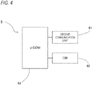
- the server 6 includes a second communication unit 61, a DB 62, and a ⁇ COM 63.
- the second communication unit 61 is a communication unit to connect to the Internet communication network 7.
- the DB 62 stores the authentication key of the charging device 2 attached to the distributed charging control device 3, registration information (installation location, use condition, surrounding information, and the like) and a reservation status of the charging device 2 to which the charging control device 3 is attached, and registration information (name, vehicle type, contact information, payment information, and the like) of the user 4.
- the ⁇ COM 63 controls the entire server 6, searches the DB 62 for the charging device 2 in response to input from the communication terminal 5, and transmits a search result to the communication terminal 5.
- the ⁇ COM 63 confirms reservation of the charging device 2 in response to the input from the communication terminal 5, and transmits the authentication key of the charging control device 3 attached to the charging device 2 to the communication terminal 5 so that a confirmed charging device 2 can be used.
- the user 4 operates the communication terminal 5 in order to reserve the charging device 2 using the charging authentication system 1 to launch the charging authentication application.
- the ⁇ COM 55 of the communication terminal 5 executes the charging authentication application.
- the communication terminal 5 determines whether the user 4 is registered in the charging authentication application (S1). If the user 4 is registered (Y in S1), the communication terminal 5 immediately proceeds to S6. If the user 4 is not registered (N in S1), the communication terminal 5 displays a registration screen Sc1 as shown in Fig. 7 on the display unit 54 (S2). When the user 4 touches "to select use plan" on the registration screen Sc1, the communication terminal 5 displays a use plan registration screen Sc2 shown in Fig. 8 .
- the communication terminal 5 transmits the registration information to the server 6 (S4), and then proceeds to S6.
- the server 6 receives the registration information and stores the registration information in the DB 62 (S5).
- the communication terminal 5 displays a search screen Sc3 as shown in Fig. 9 on the display unit 54.
- the search screen Sc3 for inputting narrowing-down conditions such as a destination, a date of use, and a time period of use as search conditions is displayed.
- a menu screen Sc4 is displayed at a lower left of the search screen Sc3, and a search result screen Sc5 is displayed at a lower right of the search screen Sc3.
- On the menu screen Sc4 a registration image of the user, a user name, and a use plan are displayed, and touch buttons for switching to a registration information change screen, a use plan change screen, a reservation list screen, and a help screen are displayed.
- a map of a surrounding is displayed before the search condition is input.
- the communication terminal 5 erases the menu screen Sc4 and enlarges the search screen Sc3 as shown in Fig. 10 .
- the communication terminal 5 transmits the search condition to the server 6 (S8).
- the server 6 receives the search condition (S9)
- the server 6 searches the charging devices 2 registered in the DB 62 for the charging device 2 that matches the search condition (S10). Thereafter, the server 6 transmits the search result to the communication terminal 5 (S11).
- the communication terminal 5 receives the search result (S12)
- the communication terminal 5 displays the search result on the search screen Sc3.
- a display example of the search result As a display example of the search result, as shown in Fig. 10 , it is considered to display an icon I1 indicating an available charging device and an icon 12 indicating an unavailable charging device among the charging devices 2 searched for on the map.
- the icon 12 When the user 4 touches the icon 12, there is a display that reservation cannot be made.
- the icon I1 an image of a place where the charging device 2 is installed, an address, a reservation date and time (date of use, time period of use), ease of parking, a fee, and a reserve button B1 are displayed.
- the charging device 2 corresponding to the touched icon I1 is input to the communication terminal 5 as the charging device 2 to be reserved (S13).
- the communication terminal 5 transmits the charging device 2 to be reserved to the server 6 (S14).
- the server 6 When the server 6 receives the charging device 2 to be reserved (S15), the server 6 confirms the reservation of the charging device 2 received in the date of use and the time period of use included in the search condition (S16), and updates the reservation status of each charging device 2 (that is, makes the time period of use of the charging device 2 for which the reservation is confirmed non-reservable). Thereafter, the server 6 transmits the authentication key of the charging device 2 for which the reservation is confirmed to the communication terminal 5 (S17). When the communication terminal 5 receives the authentication key (S18), the communication terminal 5 stores the authentication key (S19).
- the user 4 goes to a place of the charging device 2 on the date of use and the time period of use reserved by the electric vehicle 8.
- the user 4 inserts one end of the owned charging cable 9 into the outlet 32 of the charging control device 3, and inserts the other end into an outlet provided in the electric vehicle 8. That is, the charging device 2 and the electric vehicle 8 are connected using the charging cable 9.
- the user 4 operates the communication terminal 5 to launch the charging authentication application again, and transmits a charging start command and the stored authentication key to the charging control device 3 by BT communication (S20).
- charging control device 3 When the ⁇ COM 36 of the charging control device 3 (hereinafter abbreviated as “charging control device 3") receives the charging start command and the authentication key from the communication terminal 5 (S21), the ⁇ COM 36 compares the received authentication key with an authentication key stored in the ⁇ COM 36 to perform authentication (S22).
- the charging control device 3 transmits an authentication result to the communication terminal 5 (step S23), and if the authentication result fails (N in S24), the charging control device 3 immediately ends a processing, and if the authentication result succeeds (Y in S24), the charging control device 3 turns on the switch 33 to start charging and functions as a lock control unit to control the electromagnetic locking mechanism 35 to lock the charging cable 9 (S25).
- the communication terminal 5 receives the authentication result (S26), and if the authentication result succeeds (Y in S27), the communication terminal 5 transmits charging start information to the server 6 (S28). Since the charging control device 3 starts charging when the authentication succeeds, the authentication result indicating success of the authentication described above can also be referred to as the charging start information. That is, in the present embodiment, the charging start information transmitted from the charging control device 3 is transmitted to the server 6 via the communication terminal 5.
- the user 4 launches the charging authentication application on the communication terminal 5 and performs a charging end operation. Accordingly, the communication terminal 5 transmits a charging end command and the authentication key to the charging control device 3 (S29).
- the charging control device 3 receives the charging end command and the authentication key from the communication terminal 5 (S30)
- the charging control device 3 compares the received authentication key with an authentication key stored in the charging control device 3 to perform authentication (S31).
- the authentication fails (N in S32), the charging control device 3 returns to S30.
- the charging control device 3 When the authentication succeeds (Y in S32), the charging control device 3 turns off the switch 33 to stop charging and functions as the lock control unit to control the electromagnetic locking mechanism 35 to release the lock of the charging cable 9 (S33). Thereafter, the charging control device 3 transmits charging end information to the communication terminal 5 (S34), and ends a processing.
- the communication terminal 5 When the communication terminal 5 receives the charging end information from the charging control device 3 (S35), the communication terminal 5 transmits the charging end information to the server 6 (S36). Thereafter, the communication terminal 5 discards the authentication key (S37), and ends a processing.
- the server 6 When the server 6 receives the charging start information and the charging end information (S38, S39), the server 6 calculates a fee corresponding to a charging time obtained from the received charging start information and charging end information, and performs a charging settlement processing of charging (S40). In addition, the server 6 obtains vacancy information of the charging device 2 from the charging start information and the charging end information, updates the reservation status based on the vacancy information (step S41), and then ends a processing.
- the charging control device 3 starts charging by the charging device 2 when the authentication of the communication terminal 5 succeeds, so that it is possible to prevent the user 4 from erroneously using the charging device 2 that is not permitted for use.
- the communication terminal 5 transmits the charging end command for the charging device 2, and the charging control device 3 controls the charging device 2 to end the charging when the charging end command is transmitted from the communication terminal 5. Accordingly, the charging can be ended at a timing when the user wants to end the charging.
- the charging control device 3 controls the electromagnetic locking mechanism 35 to lock the charging cable 9 at the start of charging, and to release the lock of the charging cable 9 at the end of charging. Accordingly, it is possible to prevent the charging cable 9 from being stolen while the user is away from the charging device 2 during charging.
- the server 6 can charge a fee according to the charging time obtained based on the charging start information and the charging end information.
- the charging control device 3 maintains electromagnetic lock by the electromagnetic locking mechanism 35 until the charging end command is transmitted, so that the user 4 cannot retrieve the charging cable 9. Accordingly, the user 4 always operates the communication terminal 5 to prompt an end of charging, and the charging of the server 6 can be stopped.
- the server 6 can grasp vacancy situation of the charging device 2 from the charging start information and the charging end information.
- the charging control device 3 since the charging control device 3 is detachably attached to the charging device 2, an authentication function of the charging device 2 can be easily provided only by attaching the charging control device 3 to the charging device 2.
- the charging start information and the charging end information transmitted from the charging control device 3 is transmitted to the server 6 via the communication terminal 5. Accordingly, the charging control device 3 only needs to be able to perform BT communication without using the line usage fee, and does not need to perform the communication via the Internet communication network 7 that requires the line usage fee. Therefore, cost of an owner of the charging device 2 can be reduced, and the charging device 2 can be more easily provided.
- the present invention is not limited to the above-described embodiment, and modifications, improvements, and the like can be made as appropriate.
- a material, shape, size, number, arrangement position, and the like of each component in the above embodiment are optional and are not limited as long as the present invention can be achieved.
- the charging control device 3 can directly communicate with only the communication terminal 5, and transmits the charging start information and the charging end information to the server 6 via the communication terminal 5, but the present invention is not limited thereto.
- the charging control device 3 and the server 6 may communicate with each other via the Internet communication network 7 so that the charging control device 3 can directly transmit the charging start information and the charging end information to the server 6.
- the charging control device 3 is caused to perform authentication, but the present invention is not limited thereto.
- the authentication may be performed by the communication terminal 5 or the server 6.
- the charging control device 3 transmits the authentication key of the charging control device 3 to the communication terminal 5, and the communication terminal 5 compares the authentication key transmitted from the charging control device 3 with the authentication key transmitted from the server 6 in advance to perform authentication.
- the server 6 performs the authentication, for example, it is considered that the charging control device 3 and the communication terminal 5 transmit their own identification information to the server 6, and the server 6 performs the authentication based on the reservation status.
- the charging control device 3 is distributed to the owner of the charging device 2, but the present invention is not limited thereto.
- the charging control device 3 may be distributed to the user 4 who uses the charging device 2.
- the electromagnetic locking mechanism 35 is provided in the charging control device 3, but the present invention is not limited thereto.
- the electromagnetic locking mechanism 35 is not an essential component, and may be omitted.
- the server 6 calculates the fee based on the charging time and charges the fee, but the present invention is not limited thereto.
- the server 6 may calculate a fee based on an amount of charging and charge the fee.
- the charging control device 3 is detachably attached to the charging device 2 and is retrofitted to the charging device 2, but the present invention is not limited thereto.
- the charging control device may be incorporated in the charging device 2 in advance.
- an operation of the server 6 is not limited to the above-described embodiment, and when the user 4 reserves the charging device 2, when the user 4 starts charging by the charging device 2, when the user 4 ends charging by the charging device 2, or the like, the fact may be automatically distributed by a medium such as an e-mail. Accordingly, the owner can also check a usage status of the charging device 2 one by one.
- the present invention it is possible to provide a charging authentication system, a charging control device, and a charging authentication method capable of preventing a user from erroneously using a charging device that is not permitted for use.
- the present invention that provides this effect is useful for the charging authentication system, the charging control device, and the charging authentication method.
Landscapes
- Engineering & Computer Science (AREA)
- Business, Economics & Management (AREA)
- Development Economics (AREA)
- Power Engineering (AREA)
- Strategic Management (AREA)
- Economics (AREA)
- Mechanical Engineering (AREA)
- Transportation (AREA)
- General Physics & Mathematics (AREA)
- Marketing (AREA)
- Physics & Mathematics (AREA)
- General Business, Economics & Management (AREA)
- Theoretical Computer Science (AREA)
- Tourism & Hospitality (AREA)
- Accounting & Taxation (AREA)
- Finance (AREA)
- Human Resources & Organizations (AREA)
- Entrepreneurship & Innovation (AREA)
- Health & Medical Sciences (AREA)
- Quality & Reliability (AREA)
- Operations Research (AREA)
- General Health & Medical Sciences (AREA)
- Game Theory and Decision Science (AREA)
- Primary Health Care (AREA)
- Water Supply & Treatment (AREA)
- Public Health (AREA)
- Charge And Discharge Circuits For Batteries Or The Like (AREA)
- Electric Propulsion And Braking For Vehicles (AREA)
- Management, Administration, Business Operations System, And Electronic Commerce (AREA)
Abstract
Description
- The present invention relates to a charging authentication system, a charging control device, and a charging authentication method to use a charging device that charges a battery mounted on an electric vehicle.
- Examples of an electric vehicle on which a battery is mounted include an electrically powered vehicle, a hybrid vehicle, an electric bicycle, and an electric wheelchair. One of problems with widespread use of the electric vehicle (in particular, the electrically powered vehicle) is a concern that, when the number of charging stations does not increase so as to cover an entire country, charging cannot be performed when the battery runs out at an outing destination.
- Therefore, it is considered to permit others to use a charging device installed in a private house or company while an owner does not use the charging device. However, in this case, a user who wants to use the charging device may erroneously use a charging device that is not permitted for use.
- In addition, it is also considered that authentication is performed by operating an operation unit provided in a charging device (Patent Literature 1), but it is not suitable for permitting use by others.
- Patent Literature 1:
JP-A-2019-103255 - The present invention has been made in view of the above circumstances, and an object of the present invention is to provide a charging authentication system, a charging control device, and a charging authentication method capable of preventing a user from erroneously using a charging device that is not permitted for use.
- In order to achieve the above object, a charging authentication system, a charging control device, and a charging authentication method according to the present invention are characterized by the following [1] to [10].
- [1] A charging authentication system including:
- a user terminal owned by a user who desires to use a charging device for an electric vehicle and configured to transmit a charging start command for the charging device;
- an authentication unit configured to authenticate the user terminal that transmits the charging start command; and
- a charging control device connected to the charging device and configured to control the charging device to start charging when authentication by the authentication unit succeeds.
- [2] The charging authentication system according to [1], in which
- the user terminal transmits a charging end command for the charging device, and
- when the charging end command is transmitted from the user terminal, the charging control device controls the charging device to end charging.
- [3] The charging authentication system according to [2], in which
the charging control device includes an outlet into which a charging cable is inserted, a locking mechanism that locks the charging cable inserted into the outlet, and a lock control unit that controls the locking mechanism to lock the charging cable at the start of charging and to release the lock of the charging cable at the end of charging. - [4] The charging authentication system according to [2] or [3], in which
- the charging control device transmits charging start information at the start of charging and transmits charging end information at the end of charging, and
- a server is further included that calculates a fee according to a charging time obtained from the charging start information and the charging end information transmitted from the charging control device, and charges the fee.
- [5] The charging authentication system according to [4], in which
the server obtains vacancy information of the charging device based on the charging end information and the charging start information, and provides the vacancy information of the charging device to the user terminal. - [6] The charging authentication system according to any one of [1] to [5], in which
the charging control device is detachably attached to the charging device. - [7] A charging control device including:
- a plug that is insertable into an outlet provided in a charging device for an electric vehicle;
- an outlet that outputs charging power of the charging device supplied from the plug; and
- a charging control unit configured to perform wireless communication with a user terminal owned by a user who desires to use the charging device, and to output the charging power from the outlet when authentication of the user terminal succeeds.
- [8] A charging authentication method including:
- a step of transmitting, by a user terminal owned by a user who desires to use a charging device for an electric vehicle, a charging start command for the charging device;
- a step of authenticating, by an authentication unit, the user terminal that transmits the charging start command; and
- a step of controlling, by a charging control device connected to the charging device, the charging device to start charging when authentication by the authentication unit succeeds.
- [9] The charging authentication method according to [8], further including:
a step of connecting the charging device and the electric vehicle by the user using a charging cable before the user terminal transmits the charging start command. - [10] A charging authentication method including:
- a step of distributing, to an owner of a charging device, a charging control device that is detachably attached to the charging device and that controls the charging device to start charging only when authentication of a user succeeds; and
- a step of transmitting, by a user terminal owned by the user who desires to use the charging device, a charging start command for the charging device.
- According to the charging authentication system and the charging authentication method having configurations of the above [1] and [8] to [10], the charging control device starts charging by the charging device when the authentication of the user terminal succeeds, so that it is possible to prevent the user from erroneously using a charging device that is not permitted for use.
- According to the charging authentication system having a configuration of the above [2], the user terminal transmits the charging end command for the charging device, and the charging control device controls the charging device to end charging when the charging end command is transmitted from the user terminal. Accordingly, the charging can be ended at a timing when the user wants to end the charging.
- According to the charging authentication system having a configuration of the above [3], the lock control unit controls the locking mechanism to lock the charging cable at the start of charging, and to release the lock of the charging cable at the end of charging. Accordingly, it is possible to prevent the charging cable from being stolen while the user is away from the charging device during charging.
- According to the charging authentication system having a configuration of the above [4], the server can charge the fee according to the charging time obtained based on the charging start information and the charging end information.
- According to the charging authentication system having a configuration of the above [5], the server can grasp vacancy situation of the charging device from the charging start information and the charging end information.
- According to the charging authentication system and the charging control device having configurations of the above [6] and [7], since the charging control device is detachably attached to the charging device, an authentication function of the charging device can be easily provided only by attaching the charging control device to the charging device.
- According to the present invention, it is possible to provide a charging authentication system, a charging control device, and a charging authentication method capable of preventing a user from erroneously using a charging device that is not permitted for use.
- The present invention has been briefly described as above. Further, details of the present invention will be clarified by reading a mode (hereinafter, referred to as an "embodiment") for carrying out the invention to be described below with reference to the accompanying drawings.
-
- [
Fig. 1] Fig. 1 is a block diagram showing an embodiment of a charging authentication system in which a charging authentication method according to the present embodiment is implemented. - [
Fig. 2] Fig. 2 is a block diagram showing details of a charging control device shown inFig. 1 . - [
Fig. 3] Fig. 3 is a block diagram showing details of a communication terminal shown inFig. 1 . - [
Fig. 4] Fig. 4 is a block diagram showing details of a server shown inFig. 1 . - [
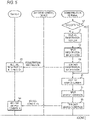
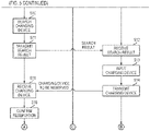
Fig. 5] Fig. 5 is a flowchart showing a processing procedure of the server, the charging control device, and the communication terminal shown inFig. 1 . - [
Fig. 6] Fig. 6 is a flowchart showing a processing procedure of the server, the charging control device, and the communication terminal shown inFig. 1 . - [
Fig. 7] Fig. 7 is an example of a registration screen displayed on the communication terminal shown inFig. 1 . - [
Fig. 8] Fig. 8 is an example of a registration screen displayed on the communication terminal shown inFig. 1 . - [
Fig. 9] Fig. 9 is an example of a search screen, a menu screen, and a search result screen displayed on the communication terminal shown inFig. 1 . - [
Fig. 10] Fig. 10 is an example of the search screen and the search result screen displayed on the communication terminal shown inFig. 1 . - A specific embodiment related to the present invention will be described below with reference to the drawings.
- A charging
authentication system 1 according to the present embodiment is a system that can search for a charging device installed in a private house, company, or the like and reserve the charging device. In the present embodiment, an electrically powered vehicle will be described as an example of an electric vehicle, but the electric vehicle may be a vehicle that travels using a battery as a drive source, and may be a hybrid vehicle, an electric bicycle, an electric motorcycle, or the like. - As shown in
Fig. 1 , the chargingauthentication system 1 includes a plurality of chargingdevices 2, a chargingcontrol device 3 detachably attached to thecharging device 2, a communication terminal 5 (user terminal) owned by auser 4 who desires to use thecharging devices 2, and aserver 6 that executes search, reservation, and the like of thecharging devices 2 by communication with thecommunication terminal 5. In the present embodiment, thecommunication terminal 5 and theserver 6 are configured to be able to communicate with each other viaInternet communication network 7. In addition, thecommunication terminal 5 and the chargingcontrol device 3 are configured to be able to wirelessly communicate with each other using, for example, Bluetooth (BT (registered trademark)) communication, which is one of wireless communication standards that do not require a line usage fee. - The charging
device 2 is installed in a detached house, a store, or the like all over the country, and has an outlet (not shown) for charging the electric vehicle. Normally, the electric vehicle can be charged by inserting a plug of a chargingcable 9 connected to the electric vehicle into the outlet. - The charging
control device 3 is a device that is insertable (detachable) into the outlet of thecharging device 2 and controls charging of thecharging device 2. As shown inFig. 2 , the chargingcontrol device 3 includes aplug 31, anoutlet 32, aswitch 33, afirst communication unit 34, an electromagnetic locking mechanism 35 (locking mechanism), a microcomputer (hereinafter, referred to as µCOM) 36, and a housing (not shown) that houses these components. - The
plug 31 is insertable into the outlet provided in thecharging device 2, and is provided on one surface of the housing. Charging power of thecharging device 2 supplied from theplug 31 is output to theoutlet 32. Theoutlet 32 is provided on a surface opposite to the one surface of the housing on which theplug 31 is provided. Theswitch 33 is provided between theplug 31 and theoutlet 32, and when theswitch 33 is turned on, the charging power is output from theoutlet 32, and when theswitch 33 is turned off, the charging power output from theoutlet 32 is cut off. - The
first communication unit 34 is a communication unit to perform BT communication with thecommunication terminal 5. Theelectromagnetic locking mechanism 35 electromagnetically locks the chargingcable 9 connected to theoutlet 32, and lock and unlock is controlled by theµCOM 36 described later. TheµCOM 36 is an understood microcomputer including a CPU, a ROM, and a RAM, and controls the entirecharging control device 3. In the ROM of theµCOM 36, an authentication key of the chargingcontrol device 3 is stored in advance. TheµCOM 36 performs authentication using the authentication key received from thecommunication terminal 5 and the authentication key stored in the ROM, and when the authentication succeeds, theswitch 33 is turned on to start charging. - The
communication terminal 5 includes, for example, a tablet, a smartphone, or the like. As shown inFig. 3 , thecommunication terminal 5 includes afirst communication unit 51, asecond communication unit 52, anoperation unit 53, adisplay unit 54, and aµCOM 55. Thefirst communication unit 51 is a communication unit to perform BT communication with the chargingcontrol device 3. Thesecond communication unit 52 is a communication unit to connect to theInternet communication network 7. Theoperation unit 53 performs various operations for using the chargingauthentication system 1. Information transmitted from theserver 6 is displayed on thedisplay unit 54. TheµCOM 55 controls theentire communication terminal 5. - In the present embodiment, as an example of the
operation unit 53 and thedisplay unit 54, a touch panel on which theoperation unit 53 and thedisplay unit 54 are integrally formed will be described. A charging authentication application distributed by an operating company operating the chargingauthentication system 1 is downloaded and stored in thecommunication terminal 5. When the charging authentication application is launched, theµCOM 55 communicates with theserver 6 via theInternet communication network 7, and can reserve thecharging device 2. After receiving the authentication key of the chargingcontrol device 3 attached to thereserved charging device 2 from theserver 6, theµCOM 55 communicates with the chargingcontrol device 3 using BT communication, and transmits the authentication key to the chargingcontrol device 3 so that thereserved charging device 2 can be used. - As shown in
Fig. 4 , theserver 6 includes asecond communication unit 61, aDB 62, and aµCOM 63. Thesecond communication unit 61 is a communication unit to connect to theInternet communication network 7. TheDB 62 stores the authentication key of thecharging device 2 attached to the distributed chargingcontrol device 3, registration information (installation location, use condition, surrounding information, and the like) and a reservation status of thecharging device 2 to which the chargingcontrol device 3 is attached, and registration information (name, vehicle type, contact information, payment information, and the like) of theuser 4. TheµCOM 63 controls theentire server 6, searches theDB 62 for thecharging device 2 in response to input from thecommunication terminal 5, and transmits a search result to thecommunication terminal 5. TheµCOM 63 confirms reservation of thecharging device 2 in response to the input from thecommunication terminal 5, and transmits the authentication key of the chargingcontrol device 3 attached to thecharging device 2 to thecommunication terminal 5 so that a confirmedcharging device 2 can be used. - Next, an operation of the charging
authentication system 1 having the above-described configuration will be described with reference toFigs. 5 and6 . Theuser 4 operates thecommunication terminal 5 in order to reserve thecharging device 2 using the chargingauthentication system 1 to launch the charging authentication application. - In response to this, the
µCOM 55 of the communication terminal 5 (hereinafter, abbreviated as the "communication terminal 5") executes the charging authentication application. When thecommunication terminal 5 executes the charging authentication application, thecommunication terminal 5 determines whether theuser 4 is registered in the charging authentication application (S1). If theuser 4 is registered (Y in S1), thecommunication terminal 5 immediately proceeds to S6. If theuser 4 is not registered (N in S1), thecommunication terminal 5 displays a registration screen Sc1 as shown inFig. 7 on the display unit 54 (S2). When theuser 4 touches "to select use plan" on the registration screen Sc1, thecommunication terminal 5 displays a use plan registration screen Sc2 shown inFig. 8 . - When the
user 4 inputs registration information (user name, vehicle type, telephone number, E-mail, credit card number, credit card expiration date, use plan) on the registration screen Sc1 and the use plan registration screen Sc2 (S3), thecommunication terminal 5 transmits the registration information to the server 6 (S4), and then proceeds to S6. Theserver 6 receives the registration information and stores the registration information in the DB 62 (S5). - In S6, the
communication terminal 5 displays a search screen Sc3 as shown inFig. 9 on thedisplay unit 54. In an example shown inFig. 9 , the search screen Sc3 for inputting narrowing-down conditions such as a destination, a date of use, and a time period of use as search conditions is displayed. A menu screen Sc4 is displayed at a lower left of the search screen Sc3, and a search result screen Sc5 is displayed at a lower right of the search screen Sc3. On the menu screen Sc4, a registration image of the user, a user name, and a use plan are displayed, and touch buttons for switching to a registration information change screen, a use plan change screen, a reservation list screen, and a help screen are displayed. On the search screen Sc3, a map of a surrounding is displayed before the search condition is input. When theuser 4 swipes the search screen Sc3, thecommunication terminal 5 erases the menu screen Sc4 and enlarges the search screen Sc3 as shown inFig. 10 . - When the
user 4 inputs the search condition on the search screen Sc3 (S7), thecommunication terminal 5 transmits the search condition to the server 6 (S8). When theserver 6 receives the search condition (S9), theserver 6 searches thecharging devices 2 registered in theDB 62 for thecharging device 2 that matches the search condition (S10). Thereafter, theserver 6 transmits the search result to the communication terminal 5 (S11). When thecommunication terminal 5 receives the search result (S12), thecommunication terminal 5 displays the search result on the search screen Sc3. - As a display example of the search result, as shown in
Fig. 10 , it is considered to display an icon I1 indicating an available charging device and anicon 12 indicating an unavailable charging device among the chargingdevices 2 searched for on the map. When theuser 4 touches theicon 12, there is a display that reservation cannot be made. When theuser 4 touches the icon I1, an image of a place where thecharging device 2 is installed, an address, a reservation date and time (date of use, time period of use), ease of parking, a fee, and a reserve button B1 are displayed. - When the
user 4 touches the icon I1 of the available chargingdevice 2 to be reserved and touches the reserve button B1, the chargingdevice 2 corresponding to the touched icon I1 is input to thecommunication terminal 5 as thecharging device 2 to be reserved (S13). When thecharging device 2 is input (S13), thecommunication terminal 5 transmits thecharging device 2 to be reserved to the server 6 (S14). - When the
server 6 receives thecharging device 2 to be reserved (S15), theserver 6 confirms the reservation of thecharging device 2 received in the date of use and the time period of use included in the search condition (S16), and updates the reservation status of each charging device 2 (that is, makes the time period of use of thecharging device 2 for which the reservation is confirmed non-reservable). Thereafter, theserver 6 transmits the authentication key of thecharging device 2 for which the reservation is confirmed to the communication terminal 5 (S17). When thecommunication terminal 5 receives the authentication key (S18), thecommunication terminal 5 stores the authentication key (S19). - Thereafter, the
user 4 goes to a place of thecharging device 2 on the date of use and the time period of use reserved by theelectric vehicle 8. Theuser 4 inserts one end of the owned chargingcable 9 into theoutlet 32 of the chargingcontrol device 3, and inserts the other end into an outlet provided in theelectric vehicle 8. That is, the chargingdevice 2 and theelectric vehicle 8 are connected using the chargingcable 9. Next, theuser 4 operates thecommunication terminal 5 to launch the charging authentication application again, and transmits a charging start command and the stored authentication key to the chargingcontrol device 3 by BT communication (S20). When theµCOM 36 of the charging control device 3 (hereinafter abbreviated as "chargingcontrol device 3") receives the charging start command and the authentication key from the communication terminal 5 (S21), theµCOM 36 compares the received authentication key with an authentication key stored in theµCOM 36 to perform authentication (S22). - Thereafter, the charging
control device 3 transmits an authentication result to the communication terminal 5 (step S23), and if the authentication result fails (N in S24), the chargingcontrol device 3 immediately ends a processing, and if the authentication result succeeds (Y in S24), the chargingcontrol device 3 turns on theswitch 33 to start charging and functions as a lock control unit to control theelectromagnetic locking mechanism 35 to lock the charging cable 9 (S25). On the other hand, thecommunication terminal 5 receives the authentication result (S26), and if the authentication result succeeds (Y in S27), thecommunication terminal 5 transmits charging start information to the server 6 (S28). Since the chargingcontrol device 3 starts charging when the authentication succeeds, the authentication result indicating success of the authentication described above can also be referred to as the charging start information. That is, in the present embodiment, the charging start information transmitted from the chargingcontrol device 3 is transmitted to theserver 6 via thecommunication terminal 5. - Thereafter, when the
user 4 leaves theelectric vehicle 8 and finishes work in a surrounding and then returns, theuser 4 launches the charging authentication application on thecommunication terminal 5 and performs a charging end operation. Accordingly, thecommunication terminal 5 transmits a charging end command and the authentication key to the charging control device 3 (S29). When the chargingcontrol device 3 receives the charging end command and the authentication key from the communication terminal 5 (S30), the chargingcontrol device 3 compares the received authentication key with an authentication key stored in the chargingcontrol device 3 to perform authentication (S31). When the authentication fails (N in S32), the chargingcontrol device 3 returns to S30. When the authentication succeeds (Y in S32), the chargingcontrol device 3 turns off theswitch 33 to stop charging and functions as the lock control unit to control theelectromagnetic locking mechanism 35 to release the lock of the charging cable 9 (S33). Thereafter, the chargingcontrol device 3 transmits charging end information to the communication terminal 5 (S34), and ends a processing. - When the
communication terminal 5 receives the charging end information from the charging control device 3 (S35), thecommunication terminal 5 transmits the charging end information to the server 6 (S36). Thereafter, thecommunication terminal 5 discards the authentication key (S37), and ends a processing. - When the
server 6 receives the charging start information and the charging end information (S38, S39), theserver 6 calculates a fee corresponding to a charging time obtained from the received charging start information and charging end information, and performs a charging settlement processing of charging (S40). In addition, theserver 6 obtains vacancy information of thecharging device 2 from the charging start information and the charging end information, updates the reservation status based on the vacancy information (step S41), and then ends a processing. - According to the above-described embodiment, the charging
control device 3 starts charging by the chargingdevice 2 when the authentication of thecommunication terminal 5 succeeds, so that it is possible to prevent theuser 4 from erroneously using thecharging device 2 that is not permitted for use. - In addition, according to the above-described embodiment, the
communication terminal 5 transmits the charging end command for thecharging device 2, and the chargingcontrol device 3 controls thecharging device 2 to end the charging when the charging end command is transmitted from thecommunication terminal 5. Accordingly, the charging can be ended at a timing when the user wants to end the charging. - In addition, according to the above-described embodiment, the charging
control device 3 controls theelectromagnetic locking mechanism 35 to lock the chargingcable 9 at the start of charging, and to release the lock of the chargingcable 9 at the end of charging. Accordingly, it is possible to prevent the chargingcable 9 from being stolen while the user is away from the chargingdevice 2 during charging. - In addition, according to the above-described embodiment, the
server 6 can charge a fee according to the charging time obtained based on the charging start information and the charging end information. In addition, according to the above-described embodiment, in order to stop charging of theserver 6, it is necessary to operate thecommunication terminal 5 to transmit the charging end command to the chargingcontrol device 3. In an actual operation, it is assumed that after theuser 4 finishes the charging, the chargingcable 9 is pulled out immediately and the charging is finished. Therefore, in the present embodiment, the chargingcontrol device 3 maintains electromagnetic lock by theelectromagnetic locking mechanism 35 until the charging end command is transmitted, so that theuser 4 cannot retrieve the chargingcable 9. Accordingly, theuser 4 always operates thecommunication terminal 5 to prompt an end of charging, and the charging of theserver 6 can be stopped. - In addition, according to the above-described embodiment, the
server 6 can grasp vacancy situation of thecharging device 2 from the charging start information and the charging end information. - In addition, according to the above-described embodiment, since the charging
control device 3 is detachably attached to thecharging device 2, an authentication function of thecharging device 2 can be easily provided only by attaching the chargingcontrol device 3 to thecharging device 2. - In addition, according to the above-described embodiment, the charging start information and the charging end information transmitted from the charging
control device 3 is transmitted to theserver 6 via thecommunication terminal 5. Accordingly, the chargingcontrol device 3 only needs to be able to perform BT communication without using the line usage fee, and does not need to perform the communication via theInternet communication network 7 that requires the line usage fee. Therefore, cost of an owner of thecharging device 2 can be reduced, and thecharging device 2 can be more easily provided. - The present invention is not limited to the above-described embodiment, and modifications, improvements, and the like can be made as appropriate. In addition, a material, shape, size, number, arrangement position, and the like of each component in the above embodiment are optional and are not limited as long as the present invention can be achieved.
- According to the above-described embodiment, the charging
control device 3 can directly communicate with only thecommunication terminal 5, and transmits the charging start information and the charging end information to theserver 6 via thecommunication terminal 5, but the present invention is not limited thereto. The chargingcontrol device 3 and theserver 6 may communicate with each other via theInternet communication network 7 so that the chargingcontrol device 3 can directly transmit the charging start information and the charging end information to theserver 6. - According to the above-described embodiment, the charging
control device 3 is caused to perform authentication, but the present invention is not limited thereto. The authentication may be performed by thecommunication terminal 5 or theserver 6. For example, when the authentication is performed by thecommunication terminal 5, it is considered that the chargingcontrol device 3 transmits the authentication key of the chargingcontrol device 3 to thecommunication terminal 5, and thecommunication terminal 5 compares the authentication key transmitted from the chargingcontrol device 3 with the authentication key transmitted from theserver 6 in advance to perform authentication. In addition, when theserver 6 performs the authentication, for example, it is considered that the chargingcontrol device 3 and thecommunication terminal 5 transmit their own identification information to theserver 6, and theserver 6 performs the authentication based on the reservation status. - In addition, according to the above-described embodiment, the charging
control device 3 is distributed to the owner of thecharging device 2, but the present invention is not limited thereto. The chargingcontrol device 3 may be distributed to theuser 4 who uses thecharging device 2. - In addition, according to the above-described embodiment, the
electromagnetic locking mechanism 35 is provided in the chargingcontrol device 3, but the present invention is not limited thereto. Theelectromagnetic locking mechanism 35 is not an essential component, and may be omitted. - In addition, according to the above-described embodiment, the
server 6 calculates the fee based on the charging time and charges the fee, but the present invention is not limited thereto. Theserver 6 may calculate a fee based on an amount of charging and charge the fee. - In addition, according to the above-described embodiment, the charging
control device 3 is detachably attached to thecharging device 2 and is retrofitted to thecharging device 2, but the present invention is not limited thereto. The charging control device may be incorporated in thecharging device 2 in advance. - In addition, an operation of the
server 6 is not limited to the above-described embodiment, and when theuser 4 reserves thecharging device 2, when theuser 4 starts charging by the chargingdevice 2, when theuser 4 ends charging by the chargingdevice 2, or the like, the fact may be automatically distributed by a medium such as an e-mail. Accordingly, the owner can also check a usage status of thecharging device 2 one by one. - Here, characteristics of the embodiment of the charging authentication system, the charging control device, and the charging authentication method according to the present invention described above are briefly summarized and listed in the following [1] to [10].
- [1] A charging authentication system (1) including:
- a user terminal (5) owned by a user (4) who desires to use a charging device (2) for an electric vehicle (8) and configured to transmit a charging start command for the charging device (2);
- an authentication unit (36) configured to authenticate the user terminal (5) that transmits the charging start command; and
- a charging control device (3) connected to the charging device (2) and configured to control the charging device (2) to start charging when authentication by the authentication unit (36) succeeds.
- [2] The charging authentication system (1) according to [1], in which
- the user terminal (5) transmits a charging end command for the charging device (2), and
- when the charging end command is transmitted from the user terminal (5), the charging control device (3) controls the charging device (2) to end charging.
- [3] The charging authentication system (1) according to [2], in which
the charging control device (3) includes an outlet (32) into which a charging cable (9) is inserted, a locking mechanism (35) that locks the charging cable (9) inserted into the outlet (32), and a lock control unit (36) that controls the locking mechanism (35) to lock the charging cable (9) at the start of charging and to release the lock of the charging cable (9) at the end of charging. - [4] The charging authentication system (1) according to [2] or [3], in which
- the charging control device (3) transmits charging start information at the start of charging and transmits charging end information at the end of charging, and
- a server (6) is further included that calculates a fee according to a charging time obtained from the charging start information and the charging end information transmitted from the charging control device (3), and charges the fee.
- [5] The charging authentication system (1) according to [4], in which
the server (6) obtains vacancy information of the charging device (2) based on the charging end information and the charging start information, and provides the vacancy information of the charging device (2) to the user terminal (5). - [6] The charging authentication system (1) according to any one of [1] to [5], in which
the charging control device (3) is detachably attached to the charging device (2). - [7] A charging control device (3) including:
- a plug (31) that is insertable into an outlet provided in a charging device (2) for an electric vehicle (8);
- an outlet (32) that outputs charging power of the charging device (2) supplied from the plug (31); and
- a charging control unit (36) configured to perform wireless communication with a user terminal (5) owned by a user (4) who desires to use the charging device (2), and to output the charging power from the outlet (32) when authentication of the user terminal (5) succeeds.
- [8] A charging authentication method including:
- a step of transmitting, by a user terminal (5) owned by a user (4) who desires to use a charging device (2) for an electric vehicle (8), a charging start command for the charging device (2);
- a step of authenticating, by an authentication unit (36), the user terminal (5) that transmits the charging start command; and
- a step of controlling, by a charging control device (3) connected to the charging device (2), the charging device (2) to start charging when authentication by the authentication unit (36) succeeds.
- [9] The charging authentication method according to [8], further including:
a step of connecting the charging device (2) and the electric vehicle (8) by the user (4) using a charging cable before the user terminal (5) transmits the charging start command. - [10] A charging authentication method including:
- a step of distributing, to an owner of a charging device (2), a charging control device (3) that is detachably attached to the charging device (2) and that controls the charging device (2) to start charging only when authentication of a user (4) succeeds; and
- a step of transmitting, by a user terminal (5) owned by the user (4) who desires to use the charging device (2), a charging start command for the charging device (2).
- Although the present invention has been described in detail with reference to a specific embodiment, it will be apparent to those skilled in the art that various changes and modifications can be made without departing from the spirit and the scope of the present invention.
- The present application is based on the Japanese patent application (
Japanese Patent Application No. 2020-034114) filed on February 28, 2020 - According to the present invention, it is possible to provide a charging authentication system, a charging control device, and a charging authentication method capable of preventing a user from erroneously using a charging device that is not permitted for use. The present invention that provides this effect is useful for the charging authentication system, the charging control device, and the charging authentication method.
-
- 2 charging device
- 3 charging control device
- 4 user
- 5 communication terminal (user terminal)
- 8 electric vehicle
- 9 charging cable
- 31 plug
- 32 outlet
- 35 electromagnetic locking mechanism (locking mechanism)
- 36 µCOM (authentication unit, lock control unit, charging control unit)
Claims (10)
- A charging authentication system comprising:a user terminal owned by a user who desires to use a charging device for an electric vehicle and configured to transmit a charging start command for the charging device;an authentication unit configured to authenticate the user terminal that transmits the charging start command; anda charging control device connected to the charging device and configured to control the charging device to start charging when authentication by the authentication unit succeeds.
- The charging authentication system according to claim 1, whereinthe user terminal transmits a charging end command for the charging device, andwhen the charging end command is transmitted from the user terminal, the charging control device controls the charging device to end charging.
- The charging authentication system according to claim 2, wherein
the charging control device includes an outlet into which a charging cable is inserted, a locking mechanism that locks the charging cable inserted into the outlet, and a lock control unit that controls the locking mechanism to lock the charging cable at the start of charging and to release the lock of the charging cable at the end of charging. - The charging authentication system according to claim 2 or 3, whereinthe charging control device transmits charging start information at the start of charging and transmits charging end information at the end of charging, anda server is further included that calculates a fee according to a charging time obtained from the charging start information and the charging end information transmitted from the charging control device, and charges the fee.
- The charging authentication system according to claim 4, wherein
the server obtains vacancy information of the charging device based on the charging end information and the charging start information, and provides the vacancy information of the charging device to the user terminal. - The charging authentication system according to any one of claims 1 to 5, wherein the charging control device is detachably attached to the charging device.
- A charging control device comprising:a plug that is insertable into an outlet provided in a charging device for an electric vehicle;an outlet that outputs charging power of the charging device supplied from the plug; anda charging control unit configured to perform wireless communication with a user terminal owned by a user who desires to use the charging device, and to output the charging power from the outlet when authentication of the user terminal succeeds.
- A charging authentication method comprising:a step of transmitting, by a user terminal owned by a user who desires to use a charging device for an electric vehicle, a charging start command for the charging device;a step of authenticating, by an authentication unit, the user terminal that transmits the charging start command; anda step of controlling, by a charging control device connected to the charging device, the charging device to start charging when authentication by the authentication unit succeeds.
- The charging authentication method according to claim 8, further comprising:
a step of connecting the charging device and the electric vehicle by the user using a charging cable before the user terminal transmits the charging start command. - A charging authentication method comprising:a step of distributing, to an owner of a charging device, a charging control device that is detachably attached to the charging device and that controls the charging device to start charging only when authentication of a user succeeds; anda step of transmitting, by a user terminal owned by the user who desires to use the charging device, a charging start command for the charging device.
Applications Claiming Priority (2)
| Application Number | Priority Date | Filing Date | Title |
|---|---|---|---|
| JP2020034114A JP7319213B2 (en) | 2020-02-28 | 2020-02-28 | Charging service system and charging service method |
| PCT/JP2021/002922 WO2021171886A1 (en) | 2020-02-28 | 2021-01-27 | Charging authentication system, charging control device, and charging authentication method |
Publications (2)
| Publication Number | Publication Date |
|---|---|
| EP4113423A1 true EP4113423A1 (en) | 2023-01-04 |
| EP4113423A4 EP4113423A4 (en) | 2023-08-02 |
Family
ID=77490463
Family Applications (1)
| Application Number | Title | Priority Date | Filing Date |
|---|---|---|---|
| EP21760445.3A Pending EP4113423A4 (en) | 2020-02-28 | 2021-01-27 | CHARGE AUTHENTICATION SYSTEM, CHARGE CONTROL DEVICE AND CHARGE AUTHENTICATION METHOD |
Country Status (5)
| Country | Link |
|---|---|
| US (1) | US12265927B2 (en) |
| EP (1) | EP4113423A4 (en) |
| JP (1) | JP7319213B2 (en) |
| CN (1) | CN115023727A (en) |
| WO (1) | WO2021171886A1 (en) |
Families Citing this family (3)
| Publication number | Priority date | Publication date | Assignee | Title |
|---|---|---|---|---|
| JP2024034507A (en) * | 2022-08-31 | 2024-03-13 | パナソニックIpマネジメント株式会社 | Management system, management method, management program, user terminal control method, user side program, host terminal control method, and host side program |
| KR102860444B1 (en) * | 2022-09-19 | 2025-09-17 | (주)클린일렉스 | Electric vehicle charging system and operating method based on information exchange between user terminal and charger |
| WO2025004314A1 (en) * | 2023-06-30 | 2025-01-02 | 株式会社Subaru | Charger |
Family Cites Families (16)
| Publication number | Priority date | Publication date | Assignee | Title |
|---|---|---|---|---|
| JP4825996B2 (en) | 2001-06-11 | 2011-11-30 | 株式会社東京アールアンドデー | Electric vehicle shared use system |
| JP2009084813A (en) * | 2007-09-28 | 2009-04-23 | Toyota Motor Corp | Vehicle key, vehicle charging system and charging key |
| JP2011164771A (en) * | 2010-02-05 | 2011-08-25 | Motion:Kk | Server and system for operation management of charging station |
| JP2011211880A (en) * | 2010-03-31 | 2011-10-20 | Motion:Kk | In-vehicle battery charging system, management server, management server control method, and program |
| JP5793245B2 (en) | 2011-07-26 | 2015-10-14 | ゴゴロ インク | Apparatus, method and article for providing vehicle diagnostic data |
| US9348381B2 (en) | 2011-10-19 | 2016-05-24 | Zeco Systems Pte Ltd | Methods and apparatuses for charging of electric vehicles |
| JP2013198230A (en) | 2012-03-16 | 2013-09-30 | Mitsubishi Motors Corp | Management operation device for charging equipment |
| EP2843613B1 (en) * | 2012-04-27 | 2017-05-10 | NEC Corporation | Charger, charging method |
| JP5730262B2 (en) * | 2012-10-18 | 2015-06-03 | オムロンオートモーティブエレクトロニクス株式会社 | In-vehicle system, vehicle control method, and vehicle control system |
| SG11201506735UA (en) * | 2013-02-27 | 2015-09-29 | Softbank Corp | Power supply system |
| JP5886333B2 (en) | 2014-02-04 | 2016-03-16 | ソフトバンク株式会社 | Power supply system |
| US20200286077A1 (en) * | 2014-05-13 | 2020-09-10 | Clear Token, Inc. | Payment And Enforcement System For Electric Vehicle Charging Stations |
| JP2019103255A (en) | 2017-12-04 | 2019-06-24 | 日東工業株式会社 | Authentication unit with authentication function added to charging means for vehicle |
| AU2019222634B2 (en) * | 2018-02-19 | 2024-09-26 | Power Hero Corp. | A method and device for converting standalone EV charging stations into intelligent stations with remote communications connectivity and control |
| JP2020034114A (en) | 2018-08-30 | 2020-03-05 | 本田技研工業株式会社 | Holding structure of ring gear |
| JP7386434B2 (en) * | 2018-11-19 | 2023-11-27 | パナソニックIpマネジメント株式会社 | Information processing method and information processing system |
-
2020
- 2020-02-28 JP JP2020034114A patent/JP7319213B2/en active Active
-
2021
- 2021-01-27 WO PCT/JP2021/002922 patent/WO2021171886A1/en not_active Ceased
- 2021-01-27 CN CN202180011626.0A patent/CN115023727A/en active Pending
- 2021-01-27 EP EP21760445.3A patent/EP4113423A4/en active Pending
-
2022
- 2022-07-18 US US17/866,974 patent/US12265927B2/en active Active
Also Published As
| Publication number | Publication date |
|---|---|
| JP7319213B2 (en) | 2023-08-01 |
| WO2021171886A1 (en) | 2021-09-02 |
| CN115023727A (en) | 2022-09-06 |
| US12265927B2 (en) | 2025-04-01 |
| EP4113423A4 (en) | 2023-08-02 |
| JP2021135955A (en) | 2021-09-13 |
| US20220351261A1 (en) | 2022-11-03 |
Similar Documents
| Publication | Publication Date | Title |
|---|---|---|
| US12265927B2 (en) | Charging authentication system, charging control device, and charging authentication method | |
| EP3174177B1 (en) | Charging system and charging start control method | |
| US11535115B2 (en) | Electric vehicle capable of providing power to another vehicle, method for controlling the same, and system | |
| JP6662965B2 (en) | Car sharing system and vehicle lending return method | |
| JP5270328B2 (en) | Electric vehicle charging system | |
| EP2716502A1 (en) | Vehicle communication apparatus | |
| JP2017068449A (en) | Car sharing system and vehicle lending and returning method | |
| JP6526300B1 (en) | Charge control system, application program and control method in charge control system | |
| CN105303653A (en) | Phone sleeve vehicle fob | |
| CN101855861A (en) | Authentication method, authentication system, vehicle-mounted device, and authentication device | |
| WO2019062964A1 (en) | Charging method and device for electric vehicle, storage medium and electric vehicle | |
| KR101769261B1 (en) | Establishing communication links automatically with local devices | |
| CN116626811A (en) | Lock release system for fusion splicing devices | |
| JP6066328B2 (en) | Infrared communication system | |
| KR101962750B1 (en) | Vehicle starting Control System by Using Face Perception Data and Method thereof | |
| JP5826640B2 (en) | Charger | |
| JP2013027249A (en) | Portable terminal, portable terminal charging system, portable terminal charging method, and program | |
| JP7182090B2 (en) | Charging service system and server device | |
| US20080294558A1 (en) | Portable electronic appliance, data processor, data communication system, computer program, data processing method | |
| US20100052881A1 (en) | Emergency starting system of vehicle and method thereof | |
| CN107862772A (en) | Gate control system with wireless induction function | |
| CN107833381B (en) | Information processing method, electronic device, and storage medium | |
| JP7271585B2 (en) | Charging service system, mobile battery, application software for mobile communication terminal, and service server for charging service | |
| JP5809071B2 (en) | Charger | |
| JP5035201B2 (en) | Portable terminal information management system, portable terminal device with portable terminal information management function, connection device with portable terminal information management function, portable terminal information management method, and portable terminal information management program |
Legal Events
| Date | Code | Title | Description |
|---|---|---|---|
| STAA | Information on the status of an ep patent application or granted ep patent |
Free format text: STATUS: THE INTERNATIONAL PUBLICATION HAS BEEN MADE |
|
| PUAI | Public reference made under article 153(3) epc to a published international application that has entered the european phase |
Free format text: ORIGINAL CODE: 0009012 |
|
| STAA | Information on the status of an ep patent application or granted ep patent |
Free format text: STATUS: REQUEST FOR EXAMINATION WAS MADE |
|
| 17P | Request for examination filed |
Effective date: 20220727 |
|
| AK | Designated contracting states |
Kind code of ref document: A1 Designated state(s): AL AT BE BG CH CY CZ DE DK EE ES FI FR GB GR HR HU IE IS IT LI LT LU LV MC MK MT NL NO PL PT RO RS SE SI SK SM TR |
|
| DAV | Request for validation of the european patent (deleted) | ||
| DAX | Request for extension of the european patent (deleted) | ||
| RAP3 | Party data changed (applicant data changed or rights of an application transferred) |
Owner name: YAZAKI CORPORATION |
|
| REG | Reference to a national code |
Ref country code: DE Ref legal event code: R079 Free format text: PREVIOUS MAIN CLASS: G06Q0050060000 Ipc: G06Q0030040000 |
|
| A4 | Supplementary search report drawn up and despatched |
Effective date: 20230705 |
|
| RIC1 | Information provided on ipc code assigned before grant |
Ipc: B60L 53/66 20190101ALI20230629BHEP Ipc: B60L 53/30 20190101ALI20230629BHEP Ipc: B60L 53/18 20190101ALI20230629BHEP Ipc: H02J 7/00 20060101ALI20230629BHEP Ipc: B60L 53/68 20190101ALI20230629BHEP Ipc: B60L 53/65 20190101ALI20230629BHEP Ipc: B60L 53/16 20190101ALI20230629BHEP Ipc: G06Q 10/02 20120101ALI20230629BHEP Ipc: G06Q 30/04 20120101AFI20230629BHEP |
|
| STAA | Information on the status of an ep patent application or granted ep patent |
Free format text: STATUS: EXAMINATION IS IN PROGRESS |
|
| 17Q | First examination report despatched |
Effective date: 20260311 |