EP4113091B1 - Battery pack leakage detection system and detection method based on tracer gas cumulative test - Google Patents
Battery pack leakage detection system and detection method based on tracer gas cumulative test Download PDFInfo
- Publication number
- EP4113091B1 EP4113091B1 EP22152741.9A EP22152741A EP4113091B1 EP 4113091 B1 EP4113091 B1 EP 4113091B1 EP 22152741 A EP22152741 A EP 22152741A EP 4113091 B1 EP4113091 B1 EP 4113091B1
- Authority
- EP
- European Patent Office
- Prior art keywords
- battery pack
- test cavity
- gas
- test
- tracer gas
- Prior art date
- Legal status (The legal status is an assumption and is not a legal conclusion. Google has not performed a legal analysis and makes no representation as to the accuracy of the status listed.)
- Active
Links
Images



Classifications
-
- G—PHYSICS
- G01—MEASURING; TESTING
- G01M—TESTING STATIC OR DYNAMIC BALANCE OF MACHINES OR STRUCTURES; TESTING OF STRUCTURES OR APPARATUS, NOT OTHERWISE PROVIDED FOR
- G01M3/00—Investigating fluid-tightness of structures
- G01M3/02—Investigating fluid-tightness of structures by using fluid or vacuum
- G01M3/04—Investigating fluid-tightness of structures by using fluid or vacuum by detecting the presence of fluid at the leakage point
- G01M3/20—Investigating fluid-tightness of structures by using fluid or vacuum by detecting the presence of fluid at the leakage point using special tracer materials, e.g. dye, fluorescent material, radioactive material
- G01M3/202—Investigating fluid-tightness of structures by using fluid or vacuum by detecting the presence of fluid at the leakage point using special tracer materials, e.g. dye, fluorescent material, radioactive material using mass spectrometer detection systems
- G01M3/205—Accessories or associated equipment; Pump constructions
-
- G—PHYSICS
- G01—MEASURING; TESTING
- G01M—TESTING STATIC OR DYNAMIC BALANCE OF MACHINES OR STRUCTURES; TESTING OF STRUCTURES OR APPARATUS, NOT OTHERWISE PROVIDED FOR
- G01M3/00—Investigating fluid-tightness of structures
- G01M3/02—Investigating fluid-tightness of structures by using fluid or vacuum
- G01M3/04—Investigating fluid-tightness of structures by using fluid or vacuum by detecting the presence of fluid at the leakage point
- G01M3/20—Investigating fluid-tightness of structures by using fluid or vacuum by detecting the presence of fluid at the leakage point using special tracer materials, e.g. dye, fluorescent material, radioactive material
- G01M3/22—Investigating fluid-tightness of structures by using fluid or vacuum by detecting the presence of fluid at the leakage point using special tracer materials, e.g. dye, fluorescent material, radioactive material for pipes, cables or tubes; for pipe joints or seals; for valves; for welds; for containers, e.g. radiators
- G01M3/223—Investigating fluid-tightness of structures by using fluid or vacuum by detecting the presence of fluid at the leakage point using special tracer materials, e.g. dye, fluorescent material, radioactive material for pipes, cables or tubes; for pipe joints or seals; for valves; for welds; for containers, e.g. radiators for pipe joints or seals
-
- G—PHYSICS
- G01—MEASURING; TESTING
- G01M—TESTING STATIC OR DYNAMIC BALANCE OF MACHINES OR STRUCTURES; TESTING OF STRUCTURES OR APPARATUS, NOT OTHERWISE PROVIDED FOR
- G01M3/00—Investigating fluid-tightness of structures
- G01M3/02—Investigating fluid-tightness of structures by using fluid or vacuum
- G01M3/04—Investigating fluid-tightness of structures by using fluid or vacuum by detecting the presence of fluid at the leakage point
- G01M3/20—Investigating fluid-tightness of structures by using fluid or vacuum by detecting the presence of fluid at the leakage point using special tracer materials, e.g. dye, fluorescent material, radioactive material
- G01M3/202—Investigating fluid-tightness of structures by using fluid or vacuum by detecting the presence of fluid at the leakage point using special tracer materials, e.g. dye, fluorescent material, radioactive material using mass spectrometer detection systems
-
- G—PHYSICS
- G01—MEASURING; TESTING
- G01M—TESTING STATIC OR DYNAMIC BALANCE OF MACHINES OR STRUCTURES; TESTING OF STRUCTURES OR APPARATUS, NOT OTHERWISE PROVIDED FOR
- G01M3/00—Investigating fluid-tightness of structures
- G01M3/02—Investigating fluid-tightness of structures by using fluid or vacuum
- G01M3/04—Investigating fluid-tightness of structures by using fluid or vacuum by detecting the presence of fluid at the leakage point
- G01M3/20—Investigating fluid-tightness of structures by using fluid or vacuum by detecting the presence of fluid at the leakage point using special tracer materials, e.g. dye, fluorescent material, radioactive material
- G01M3/22—Investigating fluid-tightness of structures by using fluid or vacuum by detecting the presence of fluid at the leakage point using special tracer materials, e.g. dye, fluorescent material, radioactive material for pipes, cables or tubes; for pipe joints or seals; for valves; for welds; for containers, e.g. radiators
- G01M3/226—Investigating fluid-tightness of structures by using fluid or vacuum by detecting the presence of fluid at the leakage point using special tracer materials, e.g. dye, fluorescent material, radioactive material for pipes, cables or tubes; for pipe joints or seals; for valves; for welds; for containers, e.g. radiators for containers, e.g. radiators
- G01M3/229—Investigating fluid-tightness of structures by using fluid or vacuum by detecting the presence of fluid at the leakage point using special tracer materials, e.g. dye, fluorescent material, radioactive material for pipes, cables or tubes; for pipe joints or seals; for valves; for welds; for containers, e.g. radiators for containers, e.g. radiators removably mounted in a test cell
-
- H—ELECTRICITY
- H01—ELECTRIC ELEMENTS
- H01M—PROCESSES OR MEANS, e.g. BATTERIES, FOR THE DIRECT CONVERSION OF CHEMICAL ENERGY INTO ELECTRICAL ENERGY
- H01M10/00—Secondary cells; Manufacture thereof
- H01M10/42—Methods or arrangements for servicing or maintenance of secondary cells or secondary half-cells
- H01M10/4228—Leak testing of cells or batteries
-
- H—ELECTRICITY
- H01—ELECTRIC ELEMENTS
- H01M—PROCESSES OR MEANS, e.g. BATTERIES, FOR THE DIRECT CONVERSION OF CHEMICAL ENERGY INTO ELECTRICAL ENERGY
- H01M10/00—Secondary cells; Manufacture thereof
- H01M10/42—Methods or arrangements for servicing or maintenance of secondary cells or secondary half-cells
- H01M10/4285—Testing apparatus
-
- H—ELECTRICITY
- H01—ELECTRIC ELEMENTS
- H01M—PROCESSES OR MEANS, e.g. BATTERIES, FOR THE DIRECT CONVERSION OF CHEMICAL ENERGY INTO ELECTRICAL ENERGY
- H01M10/00—Secondary cells; Manufacture thereof
- H01M10/42—Methods or arrangements for servicing or maintenance of secondary cells or secondary half-cells
- H01M10/48—Accumulators combined with arrangements for measuring, testing or indicating the condition of cells, e.g. the level or density of the electrolyte
-
- H—ELECTRICITY
- H01—ELECTRIC ELEMENTS
- H01M—PROCESSES OR MEANS, e.g. BATTERIES, FOR THE DIRECT CONVERSION OF CHEMICAL ENERGY INTO ELECTRICAL ENERGY
- H01M2220/00—Batteries for particular applications
- H01M2220/20—Batteries in motive systems, e.g. vehicle, ship, plane
-
- H—ELECTRICITY
- H01—ELECTRIC ELEMENTS
- H01M—PROCESSES OR MEANS, e.g. BATTERIES, FOR THE DIRECT CONVERSION OF CHEMICAL ENERGY INTO ELECTRICAL ENERGY
- H01M50/00—Constructional details or processes of manufacture of the non-active parts of electrochemical cells other than fuel cells, e.g. hybrid cells
- H01M50/10—Primary casings; Jackets or wrappings
- H01M50/183—Sealing members
-
- Y—GENERAL TAGGING OF NEW TECHNOLOGICAL DEVELOPMENTS; GENERAL TAGGING OF CROSS-SECTIONAL TECHNOLOGIES SPANNING OVER SEVERAL SECTIONS OF THE IPC; TECHNICAL SUBJECTS COVERED BY FORMER USPC CROSS-REFERENCE ART COLLECTIONS [XRACs] AND DIGESTS
- Y02—TECHNOLOGIES OR APPLICATIONS FOR MITIGATION OR ADAPTATION AGAINST CLIMATE CHANGE
- Y02E—REDUCTION OF GREENHOUSE GAS [GHG] EMISSIONS, RELATED TO ENERGY GENERATION, TRANSMISSION OR DISTRIBUTION
- Y02E60/00—Enabling technologies; Technologies with a potential or indirect contribution to GHG emissions mitigation
- Y02E60/10—Energy storage using batteries
Definitions
- the present invention relates to the technical field of battery pack leakage detection, and in particular, to a battery pack leakage detection system and detection method based on tracer gas cumulative test.
- the traditional gas detection method is influenced by various factors such as environmental temperature change, pack volume change and the like, and is therefore far from meeting the detection requirements.
- the market needs a detection method with higher precision to realize reliable waterproof grade tests corresponding to IP67 and IP68.
- Helium belongs to extremely active gas molecules and is easy to escape from tiny fine leakage positions. In order to detect the tightness of a workpiece, helium is commonly used in industry as a tracer gas, mass spectrometry is carried out on the workpiece in a vacuum box, and high-precision leakage rate measurement is rapidly realized. This method is called box vacuum helium test.
- the method needs to be carried out under vacuum, but the battery pack is easy to deform and cannot bear larger internal and external pressure difference, so that the capacity of synchronous vacuum inside and outside the battery pack is needed, to cause the internal and external pressure difference to be kept within a design range.
- a known battery pack leakage detection system and method is disclosed in CN 111 912 577 .
- the present invention provides a battery pack leakage detection system and detection method based on tracer gas cumulative test.
- the present disclosure provides a battery pack leakage detection system and detection method based on tracer gas cumulative test as set out in the appended set of claims.
- the leakage detection method of the present invention can test the sealing performance of the battery pack under the atmospheric pressure, so that the battery pack can meet the corresponding sealing grade requirements of IP67 and IP68.
- the method not only solves the problem that the traditional gas detection method cannot meet the test requirements of IP67 and IP68 due to insufficient measurement precision, but also solves the problem that the traditional vacuum helium detection method will damage the battery cells in the battery pack.
- a first embodiment of the present invention relates to a battery pack leakage detection system based on tracer gas cumulative test.
- the leakage detection system 10 is used to detect whether the sealing requirement of the battery pack 20 is satisfied or not.
- the battery pack 20 may be typically a vehicle battery pack that can be used in vehicles.
- the leakage detection system 10 includes a test container 11, a gas filling subsystem 12, a gas stirring subsystem 13, and a test analysis subsystem 14.
- the gas filling subsystem 12 is used to fill an interior of the battery pack 20 with a quantity of tracer gas, wherein the tracer gas may be helium or hydrogen or other gases which can serve as a tracer gas.
- the gas filling subsystem 12 includes a vacuumizing device 121 (such as a vacuum pump) used to vacuumize the interior of the battery pack 20, a gas filling device 122 used to fill the tracer gas into the interior of the battery pack 20, a pressure monitoring device 123 used to monitor the pressure of the tracer gas in the interior of the battery pack 20, and a concentration monitoring device 124 used to monitor the concentration of the tracer gas in the interior of the battery pack 20. Because the internal volume of the battery pack 20 is relatively large and the inner structure of the battery pack 20 is relatively complicated, the gas filling subsystem 12 needs to guarantee the filled tracer gas to be evenly distributed in the battery pack 20.
- the internal pressure of the interior of the battery pack 20 is greater than the pressure in the test cavity 111, and the tracer gas is distributed evenly in the battery pack 20, wherein the pressure in the test cavity 111 is atmospheric pressure.
- the battery pack 20 is filled with the tracer gas before it is placed into the test cavity 111.
- the battery pack 20 is filled with the tracer gas after it is placed into the test cavity 111. That is, filling the tracer into the battery pack 20 can be done either outside the test cavity 111 or inside the test cavity 111.
- the test container 11 is used to carry out the cumulative test on the battery pack 20 filled with the tracer gas, so as to determine whether the sealing requirement of the battery pack 20 is satisfied or not.
- a test cavity 111 used to accommodate the battery pack 20 is provided inside the test container 11. If the sealing performance of the battery pack 20 is not good, the filled tracer gas will leak out from the leakage hole of the battery pack 20 to the test cavity 111, the leaked tracer gas will accumulate in the test cavity 111, and the content of the tracer gas in the test cavity 111 will increase.
- the gas stirring subsystem 13 is arranged in the test cavity 111 of the test container 11.
- the gas stirring subsystem 13 is used to stir the air in the test cavity 111, so that the leaked tracer gas that leaks out from the battery pack 20 into the test cavity 111, if any, is accelerated to mix with the air in the test cavity 111 for rapidly realizing the uniform distribution of the leaked tracer gas in the test cavity 111.
- the gas stirring subsystem 13 includes at least one stirring fan 131 used for stirring the leaked tracer gas so that the leaked tracer gas is uniformly distributed in the test cavity 111.
- stirring fans 131 there are a plurality of stirring fans 131 arranged and distributed in the test cavity 111, and the position distribution and the opening frequency of the stirring fans 131 can be adjusted according to different sizes and/or shapes of the test container 11.
- the stirring fans 131 are mounted to an inner surface of a top plate (not labelled) of the test container 11. During testing, the stirring fans 131 are started in a specific frequency and mode to stir the air in the test cavity 111 to accelerate air mixing, so that the leaked tracer gas will be quickly and uniformly distributed in the test cavity 111.
- the test container 11 is a closed box for gas stirring and accumulation testing. Specifically, the test container 11 is provided with a door 112 at one side thereof for the entrance and exit of the battery pack 20. The upper side of the test container 11 is provided with a gas exhaust port 114 used to discharge the leaked tracer gas out of the test cavity 111 after the leakage detection testing is finished, so that before the next leakage detection testing begins, there is no any tracer gas in the test cavity 111.
- the gas exhaust port 114 may be provided through the top plate of the test container 11.
- a support frame 15 is provided below the test container 11, and the test container 11 is supported on the support frame 15. Further, a conveying mechanism 113 is provided in the test cavity 111, and the conveying mechanism 113 is used to convey the battery pack 20 to enter or leave the test cavity 111.
- the battery pack 20 filled with the tracer gas is placed into the test cavity 111, and the gas stirring subsystem 13 starts to work to accelerate the gas flow in the test cavity 111. Because the internal pressure of the interior of the battery pack 20 is greater than the pressure in the test cavity 111, the tracer gas in the battery pack 20 will leak into the test cavity 111 through the potential leakage hole of the battery pack 20 under the action of pressure difference and is mixed with the air in the test cavity 111. Under the stirring action of the gas stirring subsystem 13, the mixing between the leaked tracer gas and the air in the test cavity 111 is quicker and more uniform, so that the leaked tracer gas is uniformly distributed in the test cavity 111.
- the test analysis subsystem 14 is used to sample the mixed gas in the test cavity 111 and analyze the sampled gas to obtain the content of the leaked tracer gas in the test cavity 111, so as to determine whether the sealing requirement of the battery pack 20 is satisfied or not according to the content of the leaked tracer gas in the test cavity 111.
- the test analysis subsystem 14 may be typically a mass spectrum test analysis subsystem.
- the test analysis subsystem 14 includes a mass spectrometer 141 which may be a helium mass spectrometer or a hydrogen mass spectrometer and a computing device 142 which may be a computer.
- the mass spectrometer 141 is used to sample the mixed gas in the test cavity 111 and perform mass spectrum analysis on the sampled gas to determine the content of the leaked tracer gas in the test cavity 111.
- the present invention further provides a battery pack leakage detection method based on tracer gas cumulative test, which will be described below.
- a second embodiment of the present invention relates to a battery pack leakage detection method based on tracer gas cumulative test.
- the battery pack 20 is filled with the tracer gas before it is placed into the test cavity 111. That is, the battery pack 20 is filled with the tracer gas at the outside of the test container 11, and after being filled with the tracer gas, the battery pack 20 is then placed into the test container 11 for leakage detection testing.
- the leakage detection method includes the following steps:
- a third embodiment of the present invention relates to a battery pack leakage detection method based on tracer gas cumulative test.
- the battery pack 20 is filled with the tracer gas after it is placed into the test cavity 111. That is, the battery pack 20 without being filled with the tracer gas is placed into the test container 11, and then the battery pack 20 is filled with the tracer gas at the inside of the test container 11.
- the leakage detection method includes the following steps:
- the leakage detection method of the present invention can test the sealing performance of the battery pack under the atmospheric pressure, so that the battery pack can meet the corresponding sealing grade requirements of IP67 and IP68.
- the method not only solves the problem that the traditional gas detection method cannot meet the test requirements of IP67 and IP68 due to insufficient measurement precision, but also solves the problem that the traditional vacuum helium detection method will damage the battery cells in the battery pack.
Landscapes
- Physics & Mathematics (AREA)
- General Physics & Mathematics (AREA)
- Engineering & Computer Science (AREA)
- Manufacturing & Machinery (AREA)
- Chemical & Material Sciences (AREA)
- Chemical Kinetics & Catalysis (AREA)
- Electrochemistry (AREA)
- General Chemical & Material Sciences (AREA)
- Examining Or Testing Airtightness (AREA)
- Secondary Cells (AREA)
Description
- This application is based upon and claims the priority to
Chinese Patent Application No. 202110747794.8 filed on July 1, 2021 - The present invention relates to the technical field of battery pack leakage detection, and in particular, to a battery pack leakage detection system and detection method based on tracer gas cumulative test.
- With the rapid development of new energy vehicles, the waterproof protection requirement on battery packs is higher and higher, and the protection requirements of IP67 and even IP68 are provided. The traditional gas detection method is influenced by various factors such as environmental temperature change, pack volume change and the like, and is therefore far from meeting the detection requirements. The market needs a detection method with higher precision to realize reliable waterproof grade tests corresponding to IP67 and IP68.
- Helium belongs to extremely active gas molecules and is easy to escape from tiny fine leakage positions. In order to detect the tightness of a workpiece, helium is commonly used in industry as a tracer gas, mass spectrometry is carried out on the workpiece in a vacuum box, and high-precision leakage rate measurement is rapidly realized. This method is called box vacuum helium test.
- However, the method needs to be carried out under vacuum, but the battery pack is easy to deform and cannot bear larger internal and external pressure difference, so that the capacity of synchronous vacuum inside and outside the battery pack is needed, to cause the internal and external pressure difference to be kept within a design range.
- However, this will bring new problem. If the inside of the battery pack is in a vacuum state, the battery cells in the battery pack are placed in the vacuum state, and the battery cells begin to expand under the action of pressure difference, so that the safety gap of the battery cells will be damaged, and the safety of the battery pack is seriously endangered.
- A known battery pack leakage detection system and method is disclosed in
CN 111 912 577 - In view of the above, the present invention provides a battery pack leakage detection system and detection method based on tracer gas cumulative test.
- The present disclosure provides a battery pack leakage detection system and detection method based on tracer gas cumulative test as set out in the appended set of claims.
- The beneficial effects of the present invention are: the leakage detection method of the present invention can test the sealing performance of the battery pack under the atmospheric pressure, so that the battery pack can meet the corresponding sealing grade requirements of IP67 and IP68. The method not only solves the problem that the traditional gas detection method cannot meet the test requirements of IP67 and IP68 due to insufficient measurement precision, but also solves the problem that the traditional vacuum helium detection method will damage the battery cells in the battery pack.
- Hereinafter, some specific embodiments of the present invention will be described in detail in an exemplary but not restrictive manner with reference to the accompanying drawings. Those skilled in the art should understand that these drawings are not necessarily drawn to scale. In the drawings:
-
FIG. 1 is a block diagram of a battery pack leakage detection system based on tracer gas cumulative test according to a first embodiment of the present invention. -
FIG. 2 is a block diagram of a gas filling subsystem of the battery pack leakage detection system shown inFIG. 1 . -
FIG. 3 is a block diagram of a test analysis subsystem of the battery pack leakage detection system shown inFIG. 1 . -
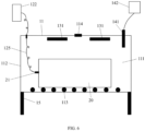
FIG. 4 is a schematic diagram of the structure used for carrying out a battery pack leakage detection method according to a second embodiment of the present invention. -
FIG. 5 is a flow chart of the battery pack leakage detection method according to the second embodiment of the present invention. -
FIG. 6 is a schematic diagram of the structure used for carrying out a battery pack leakage detection method according to a third embodiment of the present invention. -
FIG. 7 is a flow chart of the battery pack leakage detection method according to the third embodiment of the present invention. - The present invention is further described in detail with reference to the following specific embodiments and the accompanying drawings. The procedures, conditions, experimental methods and the like for carrying out the present invention are general knowledge and common general knowledge in the art except for the contents specifically mentioned below.
- Referring to
FIG. 1 to FIG. 3 , a first embodiment of the present invention relates to a battery pack leakage detection system based on tracer gas cumulative test. Theleakage detection system 10 is used to detect whether the sealing requirement of thebattery pack 20 is satisfied or not. Thebattery pack 20 may be typically a vehicle battery pack that can be used in vehicles. Theleakage detection system 10 includes atest container 11, agas filling subsystem 12, agas stirring subsystem 13, and atest analysis subsystem 14. - The
gas filling subsystem 12 is used to fill an interior of thebattery pack 20 with a quantity of tracer gas, wherein the tracer gas may be helium or hydrogen or other gases which can serve as a tracer gas. Specifically, in this embodiment, thegas filling subsystem 12 includes a vacuumizing device 121 (such as a vacuum pump) used to vacuumize the interior of thebattery pack 20, agas filling device 122 used to fill the tracer gas into the interior of thebattery pack 20, apressure monitoring device 123 used to monitor the pressure of the tracer gas in the interior of thebattery pack 20, and aconcentration monitoring device 124 used to monitor the concentration of the tracer gas in the interior of thebattery pack 20. Because the internal volume of thebattery pack 20 is relatively large and the inner structure of thebattery pack 20 is relatively complicated, thegas filling subsystem 12 needs to guarantee the filled tracer gas to be evenly distributed in thebattery pack 20. - After the tracer gas is filled into the
battery pack 20, the internal pressure of the interior of thebattery pack 20 is greater than the pressure in thetest cavity 111, and the tracer gas is distributed evenly in thebattery pack 20, wherein the pressure in thetest cavity 111 is atmospheric pressure. In an example, thebattery pack 20 is filled with the tracer gas before it is placed into thetest cavity 111. In another example, thebattery pack 20 is filled with the tracer gas after it is placed into thetest cavity 111. That is, filling the tracer into thebattery pack 20 can be done either outside thetest cavity 111 or inside thetest cavity 111. - The
test container 11 is used to carry out the cumulative test on thebattery pack 20 filled with the tracer gas, so as to determine whether the sealing requirement of thebattery pack 20 is satisfied or not. Atest cavity 111 used to accommodate thebattery pack 20 is provided inside thetest container 11. If the sealing performance of thebattery pack 20 is not good, the filled tracer gas will leak out from the leakage hole of thebattery pack 20 to thetest cavity 111, the leaked tracer gas will accumulate in thetest cavity 111, and the content of the tracer gas in thetest cavity 111 will increase. - The gas stirring
subsystem 13 is arranged in thetest cavity 111 of thetest container 11. Thegas stirring subsystem 13 is used to stir the air in thetest cavity 111, so that the leaked tracer gas that leaks out from thebattery pack 20 into thetest cavity 111, if any, is accelerated to mix with the air in thetest cavity 111 for rapidly realizing the uniform distribution of the leaked tracer gas in thetest cavity 111. Specifically, in this embodiment, thegas stirring subsystem 13 includes at least one stirringfan 131 used for stirring the leaked tracer gas so that the leaked tracer gas is uniformly distributed in thetest cavity 111. In a specific embodiment, there are a plurality of stirringfans 131 arranged and distributed in thetest cavity 111, and the position distribution and the opening frequency of the stirringfans 131 can be adjusted according to different sizes and/or shapes of thetest container 11. The stirringfans 131 are mounted to an inner surface of a top plate (not labelled) of thetest container 11. During testing, thestirring fans 131 are started in a specific frequency and mode to stir the air in thetest cavity 111 to accelerate air mixing, so that the leaked tracer gas will be quickly and uniformly distributed in thetest cavity 111. - The
test container 11 is a closed box for gas stirring and accumulation testing. Specifically, thetest container 11 is provided with adoor 112 at one side thereof for the entrance and exit of thebattery pack 20. The upper side of thetest container 11 is provided with agas exhaust port 114 used to discharge the leaked tracer gas out of thetest cavity 111 after the leakage detection testing is finished, so that before the next leakage detection testing begins, there is no any tracer gas in thetest cavity 111. Thegas exhaust port 114 may be provided through the top plate of thetest container 11. Asupport frame 15 is provided below thetest container 11, and thetest container 11 is supported on thesupport frame 15. Further, aconveying mechanism 113 is provided in thetest cavity 111, and theconveying mechanism 113 is used to convey thebattery pack 20 to enter or leave thetest cavity 111. - After the tracer gas is filled into the
battery pack 20, thebattery pack 20 filled with the tracer gas is placed into thetest cavity 111, and the gas stirringsubsystem 13 starts to work to accelerate the gas flow in thetest cavity 111. Because the internal pressure of the interior of thebattery pack 20 is greater than the pressure in thetest cavity 111, the tracer gas in thebattery pack 20 will leak into thetest cavity 111 through the potential leakage hole of thebattery pack 20 under the action of pressure difference and is mixed with the air in thetest cavity 111. Under the stirring action of the gas stirringsubsystem 13, the mixing between the leaked tracer gas and the air in thetest cavity 111 is quicker and more uniform, so that the leaked tracer gas is uniformly distributed in thetest cavity 111. - The
test analysis subsystem 14 is used to sample the mixed gas in thetest cavity 111 and analyze the sampled gas to obtain the content of the leaked tracer gas in thetest cavity 111, so as to determine whether the sealing requirement of thebattery pack 20 is satisfied or not according to the content of the leaked tracer gas in thetest cavity 111. Thetest analysis subsystem 14 may be typically a mass spectrum test analysis subsystem. In this embodiment, thetest analysis subsystem 14 includes amass spectrometer 141 which may be a helium mass spectrometer or a hydrogen mass spectrometer and acomputing device 142 which may be a computer. Themass spectrometer 141 is used to sample the mixed gas in thetest cavity 111 and perform mass spectrum analysis on the sampled gas to determine the content of the leaked tracer gas in thetest cavity 111. Thecomputing device 142 is used to calculate by the following formula to obtain the product leakage rate of thebattery pack 20.
- Q: the product leakage rate, typically in unit of mbar.l/s, or Pa.m3/s;
- ΔC: the rate of change of the content of the tracer gas in the
test cavity 111, typically in unit of %/s; - Pt: the pressure in the
test cavity 111, typically in unit of Pa; - V: the net volume in the
test cavity 111, typically in unit of m3. - Based on the above leakage detection system, the present invention further provides a battery pack leakage detection method based on tracer gas cumulative test, which will be described below.
- Referring to
FIG. 4 to FIG. 5 , a second embodiment of the present invention relates to a battery pack leakage detection method based on tracer gas cumulative test. In this embodiment, thebattery pack 20 is filled with the tracer gas before it is placed into thetest cavity 111. That is, thebattery pack 20 is filled with the tracer gas at the outside of thetest container 11, and after being filled with the tracer gas, thebattery pack 20 is then placed into thetest container 11 for leakage detection testing. The leakage detection method includes the following steps: - step 1: filling the tracer gas into the interior of the
battery pack 20;
Specifically, in step 1, thegas filling device 122 is firstly connected to thegas filling hole 21 of thebattery pack 20 through agas filling pipe 125 in the gas filling station, so that a certain amount of the tracer gas is filled into the interior of thebattery pack 20 through thegas filling device 122 and thegas filling pipe 125 at the outside of thetest container 11, and the filled tracer gas is uniformly distributed in thebattery pack 20, wherein the tracer gas may be helium or hydrogen or other gases which can serve as a tracer gas, and thegas filling pipe 125 may be a hose. During filling of the tracer gas, the pressure and concentration of the tracer gas in thebattery pack 20 are monitored respectively by thepressure monitoring device 123 and theconcentration monitoring device 124 until the pressure and concentration of the tracer gas in thebattery pack 20 meet preset requirements. After the tracer gas is filled into thebattery pack 20, thebattery pack 20 is disconnected from thegas filling pipe 125. After the tracer gas is filled into thebattery pack 20, the internal pressure of the interior of thebattery pack 20 is greater than the pressure in thetest cavity 111, so that the filled tracer gas in thebattery pack 20 will leak into thetest cavity 111 through the potential leakage hole of thebattery pack 20 under the action of pressure difference, wherein the pressure in thetest cavity 111 is atmospheric pressure. - step 2: after the
battery pack 20 is filled with the tracer gas, placing thebattery pack 20 into thetest cavity 111;
Specifically, in step 2, after thebattery pack 20 is filled with the tracer gas, thebattery pack 20 is placed into thetest cavity 111, wherein thebattery pack 20 is conveyed to enter thetest cavity 111 through the conveyingmechanism 113, and then thedoor 112 of thetest container 11 is closed. - step 3: stirring the air in the
test cavity 111 to accelerate the leaked tracer gas that leaks out from thebattery pack 20 to mix with the air in thetest cavity 111 such that the leaked tracer gas is uniformly distributed in thetest cavity 111;
Specifically, in step 3, at least one stirringfan 131 may be employed and arranged in thetest cavity 111 in order to stir the air in thetest cavity 111 to realize the uniform distribution of the leaked tracer gas in thetest cavity 111. - step 4: after the specified time period for testing is reached, sampling the mixed gas in the
test cavity 111 and analyzing the sampled gas to obtain the content of the leaked tracer gas in thetest cavity 111, so as to determine whether the sealing requirement of thebattery pack 20 is satisfied or not according to the content of the leaked tracer gas in thetest cavity 111.
Specifically, in step 4, as an example, themass spectrometer 141 is used to sample the mixed gas in thetest cavity 111 in real-time during testing and perform mass spectrum analysis in real-time on the sampled gas to obtain the rate of change of the content of the leaked tracer gas in thetest cavity 111. Finally, the product leakage rate of thebattery pack 20 is calculated by the following calculation formula:

- Q: the product leakage rate, in unit of mbar.l/s, or Pa.m3/s;
- ΔC: the rate of change of the content of the tracer gas in the
test cavity 111, in unit of %/s; - Pt: the pressure in the
test cavity 111, in unit of Pa; - V: the net volume in the
test cavity 111, in unit of m3.
- step 5: after the test is finished, opening the
door 112 of thetest container 11 and taking thebattery pack 20 out of thetest container 11. - Through the above leakage detection testing, if the product leakage rate is lower than a specified value, then it is determined that the sealing requirement of the battery pack is satisfied; if the product leakage rate is greater than the specified value, then it is determined that the sealing requirement of the battery pack is not satisfied.
- Referring to
FIG. 6 to FIG. 7 , a third embodiment of the present invention relates to a battery pack leakage detection method based on tracer gas cumulative test. In this embodiment, thebattery pack 20 is filled with the tracer gas after it is placed into thetest cavity 111. That is, thebattery pack 20 without being filled with the tracer gas is placed into thetest container 11, and then thebattery pack 20 is filled with the tracer gas at the inside of thetest container 11. The leakage detection method includes the following steps: - step 1: placing the
battery pack 20 into thetest cavity 111 and connecting thegas filling device 122 with thegas filling hole 21 of thebattery pack 20 through agas filling pipe 125;
Specifically, in step 1, thebattery pack 20 is conveyed to enter thetest cavity 111 through the conveyingmechanism 113, and after connecting thegas filling device 122 with thegas filling hole 21 of thebattery pack 20 through thegas filling pipe 125, thedoor 112 of thetest container 11 is closed, wherein thegas filling pipe 125 may be a hose. - step 2: filling the tracer gas into the interior of the
battery pack 20;
Specifically, in step 2, a certain amount of the tracer gas is filled into the interior of thebattery pack 20 through thegas filling device 122 and thegas filling pipe 125 at the inside of thetest container 11, and the filled tracer gas is uniformly distributed in thebattery pack 20, wherein the tracer gas may be helium or hydrogen or other gases which can serve as a tracer gas. During filling of the tracer gas, the pressure and concentration of the tracer gas in thebattery pack 20 are monitored respectively by thepressure monitoring device 123 and theconcentration monitoring device 124 until the pressure and concentration of the tracer gas in thebattery pack 20 meet preset requirements. After thebattery pack 20 is filled with the tracer gas, the connection between thegas filling device 122 and thegas filling pipe 125 is cut off, for example, a switch (not shown) provided on thegas filling device 122 or on thegas filling pipe 125 is turned off, so that the filled tracer gas will not escape through thegas filling pipe 125. After the tracer gas is filled into thebattery pack 20, the internal pressure of the interior of thebattery pack 20 is greater than the pressure in thetest cavity 111, so that the filled tracer gas in thebattery pack 20 will leak into thetest cavity 111 through the potential leakage hole of thebattery pack 20 under the action of pressure difference, wherein the pressure in thetest cavity 111 is atmospheric pressure. - step 3: after the
battery pack 20 is filled with the tracer gas, stirring the air in thetest cavity 111 to accelerate the leaked tracer gas that leaks out from thebattery pack 20 to mix with the air in thetest cavity 111 such that the leaked tracer gas is uniformly distributed in thetest cavity 111;
Specifically, in step 3, at least one stirringfan 131 may be employed and arranged in thetest cavity 111 in order to stir the air in thetest cavity 111 to realize the uniform distribution of the leaked tracer gas in thetest cavity 111. - step 4: after the specified time period for testing is reached, sampling the mixed gas in the
test cavity 111 and analyzing the sampled gas to obtain the content of the leaked tracer gas in thetest cavity 111, so as to determine whether the sealing requirement of thebattery pack 20 is satisfied or not according to the content of the leaked tracer gas in thetest cavity 111.
Specifically, in step 4, as an example, themass spectrometer 141 is used to sample the mixed gas in thetest cavity 111 in real-time during testing and perform mass spectrum analysis in real-time on the sampled gas to obtain the rate of change of the content of the leaked tracer gas in thetest cavity 111. Finally, the product leakage rate of thebattery pack 20 is calculated by the following calculation formula:

- Q: the product leakage rate, in unit of mbar.l/s, or Pa.m3/s;
- ΔC: the rate of change of the content of the tracer gas in the
test cavity 111, in unit of %/s; - Pt: the pressure in the
test cavity 111, in unit of Pa; - V: the net volume in the
test cavity 111, in unit of m3.
- step 5: after the test is finished, opening the
door 112 of thetest container 11, removing thegas filling pipe 125 from the gas filling hole of thebattery pack 20, and taking thebattery pack 20 out of thetest container 11. - Through the above leakage detection testing, if the product leakage rate is lower than a specified value, then it is determined that the sealing requirement of the battery pack is satisfied; if the product leakage rate is greater than the specified value, then it is determined that the sealing requirement of the battery pack is not satisfied.
- The beneficial effects of the present invention are: the leakage detection method of the present invention can test the sealing performance of the battery pack under the atmospheric pressure, so that the battery pack can meet the corresponding sealing grade requirements of IP67 and IP68. The method not only solves the problem that the traditional gas detection method cannot meet the test requirements of IP67 and IP68 due to insufficient measurement precision, but also solves the problem that the traditional vacuum helium detection method will damage the battery cells in the battery pack.
- The protection of the present invention is not limited to the above embodiments. Variations and advantages that may occur to those skilled in the art may be incorporated into the present invention without departing from the inventive concept, and the protection scope of the present invention should be defined by the appended claims.
Claims (14)
- A battery pack leakage detection system (10), comprising:a test container (11) provided with a test cavity (111) configured for accommodating the battery pack (20) therein;a gas filling subsystem (12) configured for filling an interior of the battery pack (20) with a quantity of tracer gas;a gas stirring subsystem (13) arranged in the test cavity (111) and configured for stir the air in the test cavity (111), such that the leaked tracer gas that leaks out from the battery pack (20) into the test cavity (111) is accelerated to mix with the air in the test cavity (111) for realizing the uniform distribution of the leaked tracer gas in the test cavity (111); anda test analysis subsystem (14) configured for sampling the mixed gas in the test cavity (111) and analyzing the sampled gas to obtain the content of the leaked tracer gas in the test cavity (111), so as to determine whether the sealing requirement of the battery pack (20) is satisfied or not according to the content of the leaked tracer gas in the test cavity (111);wherein the test container (11) is a closed box for housing the battery pack (20) during test of the battery pack (20),characterized in that:a support frame (15) is provided below the test container (11), and the test container (11) is supported on the support frame (15);the test container (11) is provided with a door (112) at one lateral side thereof for the entrance and exit of the battery pack (20), the gas stirring subsystem (13) comprises at least one stirring fan (131) mounted to an inner surface of a top plate of the test container (11), a conveying mechanism (113) is provided in the test cavity (111) and arranged on an inner surface of a bottom plate of the test container (11), and the conveying mechanism (113) is configured for conveying the battery pack (20) to enter or leave the test cavity (111) via the door (112).
- The system according to claim 1, wherein the gas filling subsystem (12) comprises a vacuumizing device (121) used to vacuumize the interior of the battery pack (20), a gas filling device (122) used to fill the tracer gas into the interior of the battery pack (20), a pressure monitoring device (123) used to monitor the pressure of the tracer gas in the interior of the battery pack (20), and a concentration monitoring device (124) used to monitor the concentration of the tracer gas in the interior of the battery pack (20).
- The system according to claim 1, wherein the gas filling subsystem (12) is further configured for ensuring that, after the tracer gas is filled into the battery pack (20), an internal pressure of the interior of the battery pack (20) is greater than a pressure in the test cavity (111).
- The system according to claim 1, wherein the test analysis subsystem (14) is a mass spectrum test analysis subsystem.
- The system according to claim 4, wherein the test analysis subsystem (14) comprises a mass spectrometer (141) and a computing device (142), wherein the mass spectrometer (141) is configured for sampling the mixed gas in the test cavity (111) and performing mass spectrum analysis on the sampled gas to determine the content of the leaked tracer gas in the test cavity (111), the computing device (142) is configured for calculating to obtain the product leakage rate of the battery pack (20).
- The system according to claim 1, wherein the tracer gas is helium of hydrogen.
- A battery pack leakage detection method using the battery pack leakage detection system as claimed in claim 1, comprising the following steps:step 1: filling a tracer gas into an interior of the battery pack (20);step 2: after the battery pack (20) is filled with the tracer gas, placing the battery pack (20) into the test cavity (111), wherein the battery pack (20) is conveyed to enter the test cavity through the conveying mechanism (113), and then the door (112) of the test container (11) is closed;step 3: stirring the air in the test cavity (111) to accelerate the leaked tracer gas that leaks out from the battery pack (20) to mix with the air in the test cavity (111) such that the leaked tracer gas is uniformly distributed in the test cavity (111); andstep 4: after a specified time period for testing is reached, sampling the mixed gas in the test cavity (111) and analyzing the sampled gas to obtain the content of the leaked tracer gas in the test cavity (111), so as to determine whether the sealing requirement of the battery pack (20) is satisfied or not according to the content of the leaked tracer gas in the test cavity (111).
- The method according to claim 7, wherein in step 2, after the tracer gas is filled into the battery pack (20), an internal pressure of the interior of the battery pack (20) is greater than a pressure in the test cavity (111), such that the filled tracer gas in the battery pack (20) will leak into the test cavity (111) through a potential leakage hole of the battery pack (20) under the action of pressure difference, wherein the pressure in the test cavity (111) is atmospheric pressure.
- The method according to claim 7, wherein in step 4, the mixed gas in the test cavity (111) is sampled in real-time during testing, and a mass spectrometer (141) is provided to perform mass spectrum analysis in real-time on the sampled gas to obtain the rate of change of the content of the leaked tracer gas in the test cavity (111).
- The method according to claim 9, wherein a product leakage rate of the battery pack (20) is calculated by the following calculation formula:
 Q: the product leakage rate, in unit of mbar.l/s, or Pa.m3/s;ΔC: the rate of change of the content of the tracer gas in the test cavity (111), in unit of %/s;Pt: the pressure in the test cavity (111), in unit of Pa;V: the net volume in the test cavity (111), in unit of m3;if the product leakage rate is lower than a specified value, then it is determined that the sealing requirement of the battery pack (20) is satisfied; andif the product leakage rate is greater than the specified value, then it is determined that the sealing requirement of the battery pack (20) is not satisfied.
 - A battery pack leakage detection method using the battery pack leakage detection system as claimed in claim 1, comprising the following steps:step 1: placing the battery pack (20) into the test cavity (111), wherein the battery pack (20) is conveyed to enter the test cavity through the conveying mechanism (113),
and connecting a gas filling device (122) with a gas filling hole (21) of the battery pack (20) through a gas filling pipe (125), and the door (112) of the test container (11) is closed;step 2: filling a tracer gas into an interior of the battery pack (20);step 3: after the battery pack (20) is filled with the tracer gas, stirring the air in the test cavity (111) to accelerate the leaked tracer gas that leaks out from the battery pack (20) to mix with the air in the test cavity (111) such that the leaked tracer gas is uniformly distributed in the test cavity (111); andstep 4: after a specified time period for testing is reached, sampling the mixed gas in the test cavity (111) and analyzing the sampled gas to obtain the content of the leaked tracer gas in the test cavity (111), so as to determine whether the sealing requirement of the battery pack (20) is satisfied or not according to the content of the leaked tracer gas in the test cavity (111). - The method according to claim 11, wherein in step 2, after the tracer gas is filled into the battery pack (20), an internal pressure of the interior of the battery pack (20) is greater than a pressure in the test cavity (111), such that the filled tracer gas in the battery pack (20) will leak into the test cavity (111) through a potential leakage hole of the battery pack (20) under the action of pressure difference, wherein the pressure in the test cavity (111) is atmospheric pressure.
- The method according to claim 11, wherein in step 4, the mixed gas in the test cavity (111) is sampled in real-time during testing, and a mass spectrometer (141) is provided to perform mass spectrum analysis in real-time on the sampled gas to obtain the rate of change of the content of the leaked tracer gas in the test cavity (111).
- The method according to claim 13, wherein a product leakage rate of the battery pack (20) is calculated by the following calculation formula:
 Q: the product leakage rate, in unit of mbar.l/s, or Pa.m3/s;ΔC: the rate of change of the content of the tracer gas in the test cavity (111), in unit of %/s;Pt: the pressure in the test cavity (111), in unit of Pa;V: the net volume in the test cavity (111), in unit of m3;if the product leakage rate is lower than a specified value, then it is determined that the sealing requirement of the battery pack (20) is satisfied; andif the product leakage rate is greater than the specified value, then it is determined that the sealing requirement of the battery pack (20) is not satisfied.
Applications Claiming Priority (1)
| Application Number | Priority Date | Filing Date | Title |
|---|---|---|---|
| CN202110747794.8A CN113514197B (en) | 2021-07-01 | 2021-07-01 | Vehicle battery PACK package leakage detection system and detection method based on accumulative test |
Publications (3)
| Publication Number | Publication Date |
|---|---|
| EP4113091A1 EP4113091A1 (en) | 2023-01-04 |
| EP4113091B1 true EP4113091B1 (en) | 2025-02-19 |
| EP4113091C0 EP4113091C0 (en) | 2025-02-19 |
Family
ID=78066670
Family Applications (1)
| Application Number | Title | Priority Date | Filing Date |
|---|---|---|---|
| EP22152741.9A Active EP4113091B1 (en) | 2021-07-01 | 2022-01-21 | Battery pack leakage detection system and detection method based on tracer gas cumulative test |
Country Status (5)
| Country | Link |
|---|---|
| US (1) | US11860064B2 (en) |
| EP (1) | EP4113091B1 (en) |
| JP (1) | JP7329884B2 (en) |
| CN (1) | CN113514197B (en) |
| HU (1) | HUE070799T2 (en) |
Families Citing this family (6)
| Publication number | Priority date | Publication date | Assignee | Title |
|---|---|---|---|---|
| CN115751155A (en) * | 2022-11-22 | 2023-03-07 | 广州灵帕机电科技有限公司 | Variable internal volume accumulation chamber for tracer gas accumulation leak detection system |
| JP2025030193A (en) | 2023-08-23 | 2025-03-07 | 株式会社 マルナカ | Method and device for testing resin sheet sealed products for leaks |
| CN117862043A (en) * | 2023-12-04 | 2024-04-12 | 广舜检测技术(上海)有限公司 | A method for miniaturizing high-speed helium inspection equipment for cylindrical battery cells |
| CN119936711B (en) * | 2024-01-31 | 2025-10-14 | 武汉亿纬储能有限公司 | Battery screening method, device and system |
| CN118352673B (en) * | 2024-05-23 | 2024-12-20 | 南方电网调峰调频发电有限公司储能科研院 | Overheat early-warning battery, preparation method thereof and overheat early-warning battery pack |
| CN119915444B (en) * | 2025-01-13 | 2025-09-16 | 深圳市大德激光技术有限公司 | A fully automatic helium inspection machine with spot inspection function |
Family Cites Families (17)
| Publication number | Priority date | Publication date | Assignee | Title |
|---|---|---|---|---|
| JP4671462B2 (en) * | 2000-02-22 | 2011-04-20 | パナソニック株式会社 | Airtight inspection method for nickel metal hydride secondary battery |
| CA2455063A1 (en) * | 2003-01-09 | 2004-07-09 | Ballard Power Systems Inc. | Method and apparatus for locating internal transfer leaks within fuel cell stacks |
| JP4816934B2 (en) | 2006-07-14 | 2011-11-16 | 東洋製罐株式会社 | Sealed container sealing inspection method and apparatus |
| US7905132B1 (en) * | 2007-08-14 | 2011-03-15 | LACO Technologies, Inc. | Leak testing using tracer gas permeable membrane |
| CN101738294A (en) * | 2008-11-17 | 2010-06-16 | 北京卫星环境工程研究所 | Atmosphere accumulation leak detection system and leak detection method thereof |
| JP5386319B2 (en) * | 2009-11-19 | 2014-01-15 | 株式会社アルバック | Leak detection system |
| RU2531058C2 (en) * | 2010-06-17 | 2014-10-20 | Ниссан Мотор Ко., Лтд. | Air tightness test method and air tightness tester for sealed accumulator |
| CN202631207U (en) * | 2012-04-16 | 2012-12-26 | 宁德新能源科技有限公司 | A power battery air tightness detection device |
| CN103471783A (en) * | 2013-10-09 | 2013-12-25 | 中国东方电气集团有限公司 | Nondestructive sodium battery leakage detecting method |
| CN105784288A (en) * | 2014-12-23 | 2016-07-20 | 中国电子科技集团公司第十八研究所 | Nickel-cadmium battery helium mass spectrometer leak rate test method |
| CN109425469B (en) | 2017-08-21 | 2024-05-10 | 宁德时代新能源科技股份有限公司 | Battery module and battery module air tightness detection method |
| JP6708191B2 (en) * | 2017-09-21 | 2020-06-10 | 株式会社デンソー | Leak inspection device and leak inspection method |
| IT201800005260A1 (en) * | 2018-05-11 | 2019-11-11 | METHOD FOR TIGHTNESS CHECK OF A BATTERY CELL AND RELATIVE CHECK SYSTEM | |
| CN109357819A (en) * | 2018-12-19 | 2019-02-19 | 国联汽车动力电池研究院有限责任公司 | A device and method for testing the sealing performance of a battery system box |
| EP3690419B1 (en) * | 2019-02-01 | 2021-11-03 | Sartorius Stedim Fmt Sas | System and method for detecting a possible loss of integrity of a flexible bag for biopharmaceutical product |
| CN210426902U (en) * | 2019-08-29 | 2020-04-28 | 武汉逸飞激光设备有限公司 | Helium detecting device |
| CN111912577A (en) | 2020-08-18 | 2020-11-10 | 广州小鹏汽车科技有限公司 | Detection method and device |
-
2021
- 2021-07-01 CN CN202110747794.8A patent/CN113514197B/en active Active
-
2022
- 2022-01-21 HU HUE22152741A patent/HUE070799T2/en unknown
- 2022-01-21 US US17/581,849 patent/US11860064B2/en active Active
- 2022-01-21 EP EP22152741.9A patent/EP4113091B1/en active Active
- 2022-01-31 JP JP2022012681A patent/JP7329884B2/en active Active
Also Published As
| Publication number | Publication date |
|---|---|
| EP4113091A1 (en) | 2023-01-04 |
| EP4113091C0 (en) | 2025-02-19 |
| US11860064B2 (en) | 2024-01-02 |
| JP2023008779A (en) | 2023-01-19 |
| CN113514197B (en) | 2023-04-07 |
| HUE070799T2 (en) | 2025-07-28 |
| CN113514197A (en) | 2021-10-19 |
| US20230003602A1 (en) | 2023-01-05 |
| JP7329884B2 (en) | 2023-08-21 |
Similar Documents
| Publication | Publication Date | Title |
|---|---|---|
| EP4113091B1 (en) | Battery pack leakage detection system and detection method based on tracer gas cumulative test | |
| CN103674448B (en) | Control pressurer system and space capsule junction device for detecting leak rate and method | |
| CN106525354A (en) | Leak detection system and method for gas pipeline bus housing | |
| CN109506844A (en) | A kind of ring network cabinet SF6 gas tank helium check system and method | |
| JPH10300626A (en) | Method and system for inspecting leakage | |
| EP4116691A1 (en) | Leakage detection method and leakage detection system for box | |
| CN105510174A (en) | Apparatus and method for detecting gas inside battery | |
| CN101881689A (en) | Large-capacity power lithium-ion battery sealing-performance testing equipment and test method thereof | |
| CN108802276A (en) | Gas production test system for battery cell | |
| CN117091772A (en) | Air tightness detection method and air tightness detection system | |
| JPH06265435A (en) | Airtight checking method and device | |
| JPS60111132A (en) | Leakage inspecting method of tank | |
| CN113405740A (en) | Fluoride leakage detection equipment and detection method | |
| CN222144454U (en) | Vacuum test device for leak detection | |
| CN216669170U (en) | Vehicle battery PACK package leak detection system based on accumulative test | |
| CN215178461U (en) | Pouch battery air tightness detection device | |
| JP3238242B2 (en) | Airtightness inspection method and device | |
| CN222704392U (en) | Soft pack battery exhaust device and gas measuring device | |
| CN116182075A (en) | A vehicle-mounted hydrogen cylinder helium leak detection box | |
| CN120593980B (en) | Airtightness detection method and system, controller and computer-readable storage medium | |
| CN218035544U (en) | Tightness testing device and tightness testing system | |
| CN116067574A (en) | A kind of sealing waterproof test method | |
| CN208012828U (en) | A kind of Aluminum Drum tightness tester | |
| CN109163859A (en) | A kind of automation equipment and method of quick testing product leakproofness | |
| CN221859827U (en) | A custom chip packaging leak detection machine |
Legal Events
| Date | Code | Title | Description |
|---|---|---|---|
| PUAI | Public reference made under article 153(3) epc to a published international application that has entered the european phase |
Free format text: ORIGINAL CODE: 0009012 |
|
| STAA | Information on the status of an ep patent application or granted ep patent |
Free format text: STATUS: REQUEST FOR EXAMINATION WAS MADE |
|
| 17P | Request for examination filed |
Effective date: 20220128 |
|
| AK | Designated contracting states |
Kind code of ref document: A1 Designated state(s): AL AT BE BG CH CY CZ DE DK EE ES FI FR GB GR HR HU IE IS IT LI LT LU LV MC MK MT NL NO PL PT RO RS SE SI SK SM TR |
|
| GRAP | Despatch of communication of intention to grant a patent |
Free format text: ORIGINAL CODE: EPIDOSNIGR1 |
|
| STAA | Information on the status of an ep patent application or granted ep patent |
Free format text: STATUS: GRANT OF PATENT IS INTENDED |
|
| INTG | Intention to grant announced |
Effective date: 20241129 |
|
| GRAS | Grant fee paid |
Free format text: ORIGINAL CODE: EPIDOSNIGR3 |
|
| GRAA | (expected) grant |
Free format text: ORIGINAL CODE: 0009210 |
|
| STAA | Information on the status of an ep patent application or granted ep patent |
Free format text: STATUS: THE PATENT HAS BEEN GRANTED |
|
| AK | Designated contracting states |
Kind code of ref document: B1 Designated state(s): AL AT BE BG CH CY CZ DE DK EE ES FI FR GB GR HR HU IE IS IT LI LT LU LV MC MK MT NL NO PL PT RO RS SE SI SK SM TR |
|
| REG | Reference to a national code |
Ref country code: GB Ref legal event code: FG4D |
|
| REG | Reference to a national code |
Ref country code: CH Ref legal event code: EP |
|
| REG | Reference to a national code |
Ref country code: DE Ref legal event code: R096 Ref document number: 602022010658 Country of ref document: DE |
|
| REG | Reference to a national code |
Ref country code: IE Ref legal event code: FG4D |
|
| U01 | Request for unitary effect filed |
Effective date: 20250304 |
|
| U07 | Unitary effect registered |
Designated state(s): AT BE BG DE DK EE FI FR IT LT LU LV MT NL PT RO SE SI Effective date: 20250312 |
|
| PG25 | Lapsed in a contracting state [announced via postgrant information from national office to epo] |
Ref country code: RS Free format text: LAPSE BECAUSE OF FAILURE TO SUBMIT A TRANSLATION OF THE DESCRIPTION OR TO PAY THE FEE WITHIN THE PRESCRIBED TIME-LIMIT Effective date: 20250519 |
|
| PG25 | Lapsed in a contracting state [announced via postgrant information from national office to epo] |
Ref country code: PL Free format text: LAPSE BECAUSE OF FAILURE TO SUBMIT A TRANSLATION OF THE DESCRIPTION OR TO PAY THE FEE WITHIN THE PRESCRIBED TIME-LIMIT Effective date: 20250219 |
|
| PG25 | Lapsed in a contracting state [announced via postgrant information from national office to epo] |
Ref country code: ES Free format text: LAPSE BECAUSE OF FAILURE TO SUBMIT A TRANSLATION OF THE DESCRIPTION OR TO PAY THE FEE WITHIN THE PRESCRIBED TIME-LIMIT Effective date: 20250219 |
|
| PG25 | Lapsed in a contracting state [announced via postgrant information from national office to epo] |
Ref country code: NO Free format text: LAPSE BECAUSE OF FAILURE TO SUBMIT A TRANSLATION OF THE DESCRIPTION OR TO PAY THE FEE WITHIN THE PRESCRIBED TIME-LIMIT Effective date: 20250519 Ref country code: IS Free format text: LAPSE BECAUSE OF FAILURE TO SUBMIT A TRANSLATION OF THE DESCRIPTION OR TO PAY THE FEE WITHIN THE PRESCRIBED TIME-LIMIT Effective date: 20250619 |
|
| PG25 | Lapsed in a contracting state [announced via postgrant information from national office to epo] |
Ref country code: HR Free format text: LAPSE BECAUSE OF FAILURE TO SUBMIT A TRANSLATION OF THE DESCRIPTION OR TO PAY THE FEE WITHIN THE PRESCRIBED TIME-LIMIT Effective date: 20250219 |
|
| REG | Reference to a national code |
Ref country code: HU Ref legal event code: AG4A Ref document number: E070799 Country of ref document: HU |
|
| PG25 | Lapsed in a contracting state [announced via postgrant information from national office to epo] |
Ref country code: SM Free format text: LAPSE BECAUSE OF FAILURE TO SUBMIT A TRANSLATION OF THE DESCRIPTION OR TO PAY THE FEE WITHIN THE PRESCRIBED TIME-LIMIT Effective date: 20250219 |
|
| PG25 | Lapsed in a contracting state [announced via postgrant information from national office to epo] |
Ref country code: CZ Free format text: LAPSE BECAUSE OF FAILURE TO SUBMIT A TRANSLATION OF THE DESCRIPTION OR TO PAY THE FEE WITHIN THE PRESCRIBED TIME-LIMIT Effective date: 20250219 |
|
| PG25 | Lapsed in a contracting state [announced via postgrant information from national office to epo] |
Ref country code: SK Free format text: LAPSE BECAUSE OF FAILURE TO SUBMIT A TRANSLATION OF THE DESCRIPTION OR TO PAY THE FEE WITHIN THE PRESCRIBED TIME-LIMIT Effective date: 20250219 |
|
| PLBE | No opposition filed within time limit |
Free format text: ORIGINAL CODE: 0009261 |
|
| STAA | Information on the status of an ep patent application or granted ep patent |
Free format text: STATUS: NO OPPOSITION FILED WITHIN TIME LIMIT |
|
| 26N | No opposition filed |
Effective date: 20251120 |
|
| U20 | Renewal fee for the european patent with unitary effect paid |
Year of fee payment: 5 Effective date: 20251224 |
|
| PGFP | Annual fee paid to national office [announced via postgrant information from national office to epo] |
Ref country code: HU Payment date: 20251223 Year of fee payment: 5 |