EP4112964A1 - Bremssattelabdeckungsanordnung und herstellungsverfahren dafür - Google Patents
Bremssattelabdeckungsanordnung und herstellungsverfahren dafür Download PDFInfo
- Publication number
- EP4112964A1 EP4112964A1 EP20926308.6A EP20926308A EP4112964A1 EP 4112964 A1 EP4112964 A1 EP 4112964A1 EP 20926308 A EP20926308 A EP 20926308A EP 4112964 A1 EP4112964 A1 EP 4112964A1
- Authority
- EP
- European Patent Office
- Prior art keywords
- bracket
- caliper cover
- caliper
- cover body
- installation
- Prior art date
- Legal status (The legal status is an assumption and is not a legal conclusion. Google has not performed a legal analysis and makes no representation as to the accuracy of the status listed.)
- Granted
Links
Images

Classifications
-
- F—MECHANICAL ENGINEERING; LIGHTING; HEATING; WEAPONS; BLASTING
- F16—ENGINEERING ELEMENTS AND UNITS; GENERAL MEASURES FOR PRODUCING AND MAINTAINING EFFECTIVE FUNCTIONING OF MACHINES OR INSTALLATIONS; THERMAL INSULATION IN GENERAL
- F16D—COUPLINGS FOR TRANSMITTING ROTATION; CLUTCHES; BRAKES
- F16D65/00—Parts or details
- F16D65/005—Components of axially engaging brakes not otherwise provided for
- F16D65/0068—Brake calipers
- F16D65/0075—Brake calipers assembled from a plurality of parts
-
- F—MECHANICAL ENGINEERING; LIGHTING; HEATING; WEAPONS; BLASTING
- F16—ENGINEERING ELEMENTS AND UNITS; GENERAL MEASURES FOR PRODUCING AND MAINTAINING EFFECTIVE FUNCTIONING OF MACHINES OR INSTALLATIONS; THERMAL INSULATION IN GENERAL
- F16D—COUPLINGS FOR TRANSMITTING ROTATION; CLUTCHES; BRAKES
- F16D65/00—Parts or details
- F16D65/005—Components of axially engaging brakes not otherwise provided for
- F16D65/0081—Brake covers
-
- F—MECHANICAL ENGINEERING; LIGHTING; HEATING; WEAPONS; BLASTING
- F16—ENGINEERING ELEMENTS AND UNITS; GENERAL MEASURES FOR PRODUCING AND MAINTAINING EFFECTIVE FUNCTIONING OF MACHINES OR INSTALLATIONS; THERMAL INSULATION IN GENERAL
- F16D—COUPLINGS FOR TRANSMITTING ROTATION; CLUTCHES; BRAKES
- F16D65/00—Parts or details
- F16D65/02—Braking members; Mounting thereof
-
- F—MECHANICAL ENGINEERING; LIGHTING; HEATING; WEAPONS; BLASTING
- F16—ENGINEERING ELEMENTS AND UNITS; GENERAL MEASURES FOR PRODUCING AND MAINTAINING EFFECTIVE FUNCTIONING OF MACHINES OR INSTALLATIONS; THERMAL INSULATION IN GENERAL
- F16D—COUPLINGS FOR TRANSMITTING ROTATION; CLUTCHES; BRAKES
- F16D55/00—Brakes with substantially-radial braking surfaces pressed together in axial direction, e.g. disc brakes
- F16D2055/0004—Parts or details of disc brakes
- F16D2055/0016—Brake calipers
- F16D2055/002—Brake calipers assembled from a plurality of parts
-
- F—MECHANICAL ENGINEERING; LIGHTING; HEATING; WEAPONS; BLASTING
- F16—ENGINEERING ELEMENTS AND UNITS; GENERAL MEASURES FOR PRODUCING AND MAINTAINING EFFECTIVE FUNCTIONING OF MACHINES OR INSTALLATIONS; THERMAL INSULATION IN GENERAL
- F16D—COUPLINGS FOR TRANSMITTING ROTATION; CLUTCHES; BRAKES
- F16D55/00—Brakes with substantially-radial braking surfaces pressed together in axial direction, e.g. disc brakes
- F16D2055/0004—Parts or details of disc brakes
- F16D2055/0037—Protective covers
-
- F—MECHANICAL ENGINEERING; LIGHTING; HEATING; WEAPONS; BLASTING
- F16—ENGINEERING ELEMENTS AND UNITS; GENERAL MEASURES FOR PRODUCING AND MAINTAINING EFFECTIVE FUNCTIONING OF MACHINES OR INSTALLATIONS; THERMAL INSULATION IN GENERAL
- F16D—COUPLINGS FOR TRANSMITTING ROTATION; CLUTCHES; BRAKES
- F16D2250/00—Manufacturing; Assembly
- F16D2250/0084—Assembly or disassembly
Definitions
- Embodiments of the present application relate to the field of automotive accessories, and in particular to a caliper cover assembly and a production method thereof.
- caliper covers There are two forms of common caliper covers. One is made of early plastic material, and is fixed by glue, which is easy to be deformed and damaged after long-term use, thus affecting the driving safety of vehicle; the other is made of aluminum alloy material, in which an improved is made from glue bonding to fixation by screws. A shell and a bracket of such caliper cover are welded and fixed according to different profiles of the brake caliper during the installation process, and a bending process is carried out. Due to the unstable relationship between production tolerance and welding firmness, a lot of problems arise when installing the product; for example: 1. the degree of fit is poor; 2. the connection position of the shell and the bracket is prone to breakage; 3.
- a buckle is inserted into a gap between the brake caliper bracket and a top of a brake disc for fixed installation, wherein the buckle is greatly influenced by the gap and installation space, is prone to deformation, and will rub against the brake disc to produce abnormal noise and wear.
- embodiments of the present application provide a caliper cover assembly and a production method thereof, so as to solve the problem of interfering stability and safety of existing caliper covers.
- a caliper cover assembly includes a caliper cover body, a first bracket, a second bracket, and buckles; the first bracket and the second bracket are respectively integrally formed with the caliper cover body; the first bracket and the second bracket are symmetrically disposed, and are respectively provided with an installation hole; the buckles are provided in two; the two buckles are symmetrically disposed, separately disposed on the first bracket and the second bracket, and fixedly connected with the first bracket or the second bracket through bolts passing through the installation holes respectively.
- the first bracket includes a first straight portion, a first inclined portion, and a first vertical portion that are connected in sequence, and the first straight portion, the first inclined portion and the first vertical portion are integrally formed;
- the second bracket includes a second straight portion, a second inclined portion, and a second vertical portion that are connected in sequence, and the second straight portion, the second inclined portion, and the second vertical portion are integrally formed;
- the first straight portion and the second straight portion are symmetrically disposed, the first inclined portion and the second inclined portion are symmetrically disposed, and the first vertical portion and the second vertical portion are symmetrically disposed;
- the installation holes are disposed in the first vertical portion and the second vertical portion.
- a limiting protrusion is disposed at an end of the first straight portion that is away from the first inclined portion, and the limiting protrusion is integrally formed with the first straight portion.
- an installation groove is disposed in the first vertical portion and the second vertical portion respectively.
- the buckle includes an installation portion, a connecting portion, and a limiting portion.
- One end of the installation portion is fixedly connected to the connecting portion, and the installation portion is fixed to the first bracket or the second bracket by bolts.
- a length direction of the connecting portion is along a width direction of the installation portion, and the connecting portion is perpendicular to the installation portion.
- the limiting portion is coplanar with the connecting portion, and a length direction of the limiting portion is perpendicular to the length direction of the connecting portion.
- the limiting portion and the installation portion are disposed in a staggered manner in the length direction of the connecting portion.
- a side of the caliper cover body that is connected to the first bracket and the second bracket is provided with a limiting ring plate that surrounds an edge of the caliper cover body by one turn, and the limiting ring plate is integrally formed with the caliper cover body.
- first bracket and the second bracket are connected to a side of the limiting ring plate that is away from the caliper cover body.
- first bracket, the second bracket and the limiting ring plate are respectively provided with thermally conductive silicone.
- the caliper cover body is made of aluminum alloy.
- the present application also provides a method for producing a caliper cover assembly, which includes the following steps:
- the caliper cover body, the first bracket and the second bracket are integrally formed, the structure is firm, and breakage is not easy to occur at the connection position, which is advantageous for driving safety; the structure of the first bracket and the second bracket can better fit the brake caliper and leads to a good stability; the buckles can be clamped and fixed with the brake caliper, and there is no need to insert them into the gap between the brake caliper bracket and the top of the brake disc, so the installation adaptability is better; the first bracket, the second bracket and the limiting ring plate are respectively provided with thermally conductive silicone so that heat conduction can be accelerated and the caliper cover assembly is prevented from affecting heat dissipation of the brake caliper.
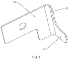
- the embodiment of the present application provides a caliper cover assembly which, as shown in FIGS. 1 to 3 , includes a caliper cover body 1, a first bracket 2, a second bracket 3 and buckles 4, wherein a decorative oil pipe, a decorative grease nipple and decorative nails are provided on the caliper cover body 1.
- the caliper cover body 1 is configured to be installed on the side of the brake caliper to block the brake caliper and increase the aesthetic effect of the brake caliper; the first bracket 2 and the second bracket 3 are respectively integrally formed with the caliper cover body 1 so that the connection structure of the first bracket 2, the second bracket 3 and the caliper cover is firm and reliable, and is not easy to break.
- the first bracket 2 and the second bracket 3 are symmetrically disposed at two ends of an upper portion on one side of the caliper cover body 1.
- the first bracket 2 and the second bracket 3 are respectively provided with an installation hole 232, which is a through hole penetrating the first bracket 2 or the second bracket 3.
- the two buckles 4 are symmetrically disposed with respect to a plane perpendicular to a length direction of the caliper cover body 1.
- the symmetry plane of the first bracket 2 and the second bracket 3 is coplanar with the symmetry plane of the two buckles 4.
- the two buckles 4 are disposed on the first bracket 2 and the second bracket 3 separately, and are fixedly connected to the first bracket 2 or the second bracket 3 by bolts passing through the installation holes 232 respectively.
- the buckles 4 can play a fixing function.
- the first bracket 2 includes a first straight portion 21, a first inclined portion 22, and a first vertical portion 23 that are connected in sequence.
- Each of the first straight portion 21, the first inclined portion 22 and the first vertical portion 23 is an elongated strip-shaped plate, and is fixed to one side of the caliper cover in a perpendicular manner, wherein the first straight portion 21 is perpendicular to the symmetry plane of the first bracket 2 and the second bracket 3, and the first vertical portion is parallel to the symmetry plane of the first bracket 2 and the second bracket 3;
- the first inclined portion 22 connects the first straight portion 21 and the first vertical portion, and the first straight portion 21, the first inclined portion 22 and the first vertical portion 23 are integrally formed;
- the second bracket 3 includes a second straight portion 31, a second inclined portion 32, and a second vertical portion 33 that are connected in sequence; the second straight portion 31, the second inclined portion 32 and the second vertical portion 33 are integrally formed.
- the first straight portion 21 and the second straight portion 22 are symmetrically disposed, the first inclined portion 22 and the second inclined portion 32 are symmetrically disposed, and the first vertical portion 23 and the second vertical portion 33 are symmetrically disposed.
- the installation holes 232 are disposed in the first vertical portion 23 and the second vertical portion 33, and the buckles 4 are fixed on the first vertical portion or the second vertical portion by bolts.
- the first bracket 2 and the second brackets 3 are respectively overlapped on two shoulders on the upper end of the brake caliper, and the buckles 4 abut against a side of the brake caliper that is away from the caliper cover body 1, so that the caliper cover assembly is fixed to the outer side of the brake caliper.
- a lower side on an end of the first straight portion 21 that is away from the first inclined portion 22 is provided with a limiting protrusion 24.
- the limiting protrusion 24 is integrally formed with the first straight portion 21, and the limiting protrusion 24 can limit the first bracket 2 during the installation process.
- the first bracket 2 is installed in place through the limiting protrusion 24, and then the buckles 4 on the first bracket 2 and the second bracket 3 are fine-tuned according to the actual size of the brake caliper.
- the caliper cover assembly and the brake caliper are connected more closely.
- the first vertical portion 23 and the second vertical portion 33 are respectively provided with an installation groove 231
- the installation groove 231 is provided with a notch at one end that is away from the caliper cover body 1, and the installation hole 232 is located in the installation groove 231.
- the width of the installation groove 231 is the same as the width of the buckle 4 at a position where it fits the first vertical portion 23 and the second vertical portion 33.
- the installation grooves 231 can make the connection between the buckles 4 and the first bracket 2 or the second bracket 3 more stable, and no rotation will occur.
- the buckle 4 includes an installation portion 41, a connecting portion 42, and a limiting portion 43.
- Each of the installation portion 41, the connecting portion 42 and the limiting portion 43 has a plate-shaped structure.
- the installation portion 41 is fixed to the first bracket 2 or the second bracket 3 by bolts.
- the installation portion 41 is located in the installation groove 231, and one end of the installation portion 41 is fixedly connected to the connecting portion 42.
- a length direction of the connecting portion 42 is along a width direction of the installation portion 41.
- the length of the connecting portion 42 is larger than the width of the installation portion 41.
- the connecting portion 42 is perpendicular to the installation portion 41.
- the limiting portion 43 is coplanar with the connecting portion 42, and a length direction of the limiting portion 43 is perpendicular to the length direction of the connecting portion 42.
- the limiting portion 43 and the installation portion 41 are disposed in a staggered manner in the length direction of the connecting portion 42.
- the limiting portion 43 and the first straight portion 21 or the second straight portion 31 clamp on upper and lower sides of the caliper
- the limiting portion 43 and the caliper cover body 1 clamp on front and rear sides of the caliper
- the first vertical portion 23 and the second vertical portion 33 clamp on left and right sides of the caliper, so that the caliper cover assembly can be firmly installed on the caliper.
- a side of the caliper cover body 1 that is connected to the first bracket 2 and the second bracket 3 is provided with a limiting ring plate 11 that surrounds an edge of the caliper cover body 1 by one turn.
- a width direction of the limiting ring plate 11 is perpendicular to the caliper cover body 1, and the limiting ring plate 11 is integrally formed with the caliper cover body 1.
- the limiting ring plate 11 can fit the edge of the caliper to further increase the stability of the installation of the caliper cover assembly.
- the first bracket 2 and the second bracket 3 are connected to a side of the limiting ring plate 11 that is away from the caliper cover body 1, so that the first bracket 2 and the second bracket 3 occupy a small space on the side of the caliper cover body 1 that is close to the caliper.
- the degree of fit between the caliper cover body 1 and the caliper is higher.
- the first bracket 2, the second bracket 3 and the limiting ring plate 11 are respectively provided with thermally conductive silicone 5, and the thermally conductive silicone 5 is located on sides of the first bracket 2, the second bracket 3 and the limiting ring plate that fit the caliper.
- the heat generated on the caliper can be quickly transferred to the first bracket 2, the second bracket 3, the limiting ring plate 11 and the caliper cover body 1 through the thermally conductive silicone 5, which solves the problem of the caliper cover affecting heat dissipation of the caliper.
- the caliper cover body 1 is made of aluminum alloy, which has good thermal conductivity, avoids overheating of the caliper, and has the advantages of good firmness, long service life, resistance to oxidation and easy processing.
- the caliper cover assembly provided by the present application has a high degree of fit with the caliper, has a firm structure, is not prone to breakage, is not affected by gaps during installation, is more convenient to install, has good thermal conductivity, and has a higher degree of safety in use.
- the embodiment of the present application provides a method for producing a caliper cover assembly, which includes the following steps:
- the caliper cover body 1 is integrally formed with the first bracket 2 and the second bracket 3 so that the connection firmness of the caliper cover body 1 with the first bracket 2 and the second bracket 3 is better, and breakage is less likely to occur as compared to welding.
Landscapes
- Engineering & Computer Science (AREA)
- General Engineering & Computer Science (AREA)
- Mechanical Engineering (AREA)
- Braking Arrangements (AREA)
Applications Claiming Priority (2)
| Application Number | Priority Date | Filing Date | Title |
|---|---|---|---|
| CN202010187278.XA CN111306222A (zh) | 2020-03-17 | 2020-03-17 | 卡钳罩组件及其生产方法 |
| PCT/CN2020/109136 WO2021184658A1 (zh) | 2020-03-17 | 2020-08-14 | 卡钳罩组件及其生产方法 |
Publications (4)
| Publication Number | Publication Date |
|---|---|
| EP4112964A1 true EP4112964A1 (de) | 2023-01-04 |
| EP4112964A4 EP4112964A4 (de) | 2023-08-23 |
| EP4112964C0 EP4112964C0 (de) | 2024-07-10 |
| EP4112964B1 EP4112964B1 (de) | 2024-07-10 |
Family
ID=71157228
Family Applications (1)
| Application Number | Title | Priority Date | Filing Date |
|---|---|---|---|
| EP20926308.6A Active EP4112964B1 (de) | 2020-03-17 | 2020-08-14 | Bremssattelabdeckungsanordnung und herstellungsverfahren dafür |
Country Status (8)
| Country | Link |
|---|---|
| US (1) | US12078217B2 (de) |
| EP (1) | EP4112964B1 (de) |
| JP (1) | JP7523566B2 (de) |
| KR (1) | KR20230002398A (de) |
| CN (1) | CN111306222A (de) |
| CA (1) | CA3132016C (de) |
| ES (1) | ES2986508T3 (de) |
| WO (1) | WO2021184658A1 (de) |
Families Citing this family (4)
| Publication number | Priority date | Publication date | Assignee | Title |
|---|---|---|---|---|
| USD921547S1 (en) * | 2018-01-22 | 2021-06-08 | Marshall Genuine Products, Llc | Caliper cover |
| CN111306222A (zh) | 2020-03-17 | 2020-06-19 | 张建平 | 卡钳罩组件及其生产方法 |
| CN217814657U (zh) * | 2022-08-01 | 2022-11-15 | 漳州车马如龙汽车科技有限公司 | 安全卡钳罩 |
| EP4656897A1 (de) * | 2024-05-27 | 2025-12-03 | ZF CV Systems Europe BV | Sattelabdeckungsanordnung für einen bremssattel, bremssattelbaugruppe für eine kraftfahrzeug-scheibenbremse sowie nutzfahrzeug-scheibenbremse |
Family Cites Families (21)
| Publication number | Priority date | Publication date | Assignee | Title |
|---|---|---|---|---|
| US20040074716A1 (en) | 2002-09-13 | 2004-04-22 | Harco Industries, Inc. | Caliper brake cover for use with a motor vehicle wheel |
| US20050258008A1 (en) * | 2004-05-20 | 2005-11-24 | King William J | Caliper cover |
| JP4794286B2 (ja) * | 2005-11-29 | 2011-10-19 | 株式会社ショーワ | 電動パワーステアリング装置 |
| US9046143B2 (en) * | 2008-06-25 | 2015-06-02 | Michael T. Barland | Caliper cover |
| JP5715932B2 (ja) * | 2011-11-18 | 2015-05-13 | 本田技研工業株式会社 | ディスクブレーキ装置 |
| DE102013100178A1 (de) * | 2013-01-09 | 2014-07-10 | Knorr-Bremse Systeme für Nutzfahrzeuge GmbH | Scheibenbremse für ein Nutzfahrzeug |
| DE102016008840A1 (de) * | 2016-07-19 | 2018-01-25 | Lucas Automotive Gmbh | Schutzblende sowie Bremsträger und Schwimmsattelbremse mit einer solchen Schutzblende |
| US10066687B2 (en) * | 2016-10-04 | 2018-09-04 | Michael Barland | Caliper cover |
| JP6547722B2 (ja) * | 2016-10-31 | 2019-07-24 | 株式会社アドヴィックス | ディスクブレーキ装置 |
| CN107237845A (zh) * | 2017-08-15 | 2017-10-10 | 张建平 | 一种汽车刹车卡钳罩连接与紧固方法 |
| CN107289045A (zh) * | 2017-08-15 | 2017-10-24 | 张建平 | 一种可变装配式汽车刹车卡钳罩 |
| US20190084638A1 (en) * | 2017-09-21 | 2019-03-21 | Thomas W. Melcher | Leaning Quad-Wheeled All-Terrain Vehicle |
| IT201800002973A1 (it) * | 2018-02-23 | 2019-08-23 | Freni Brembo Spa | Corpo pinza fisso per un disco di freno a disco |
| KR101942683B1 (ko) * | 2018-05-02 | 2019-01-25 | 박진수 | 캘리퍼 커버 |
| CN108980235A (zh) * | 2018-09-25 | 2018-12-11 | 张建平 | 小空间轮毂专用汽车卡钳罩 |
| CN209604449U (zh) * | 2018-11-29 | 2019-11-08 | 江再富 | 一种汽车碟式制动器的卡钳罩 |
| CN209458317U (zh) * | 2018-12-26 | 2019-10-01 | 胡舜娟 | 汽车刹车卡钳保护罩连接结构 |
| CN209875797U (zh) * | 2019-02-22 | 2019-12-31 | 江再富 | 一种可调式汽车碟式制动器的卡钳罩 |
| CN113819171B (zh) * | 2019-08-23 | 2023-05-12 | 张建平 | 一种汽车卡钳罩的固定结构 |
| CN111306222A (zh) * | 2020-03-17 | 2020-06-19 | 张建平 | 卡钳罩组件及其生产方法 |
| CN211852591U (zh) * | 2020-03-17 | 2020-11-03 | 张建平 | 卡钳罩组件 |
-
2020
- 2020-03-17 CN CN202010187278.XA patent/CN111306222A/zh active Pending
- 2020-08-14 EP EP20926308.6A patent/EP4112964B1/de active Active
- 2020-08-14 ES ES20926308T patent/ES2986508T3/es active Active
- 2020-08-14 KR KR1020227035354A patent/KR20230002398A/ko not_active Ceased
- 2020-08-14 JP JP2022556131A patent/JP7523566B2/ja active Active
- 2020-08-14 US US17/603,010 patent/US12078217B2/en active Active
- 2020-08-14 WO PCT/CN2020/109136 patent/WO2021184658A1/zh not_active Ceased
- 2020-08-14 CA CA3132016A patent/CA3132016C/en active Active
Also Published As
| Publication number | Publication date |
|---|---|
| EP4112964A4 (de) | 2023-08-23 |
| JP2023518436A (ja) | 2023-05-01 |
| CN111306222A (zh) | 2020-06-19 |
| US12078217B2 (en) | 2024-09-03 |
| WO2021184658A1 (zh) | 2021-09-23 |
| CA3132016C (en) | 2023-10-31 |
| EP4112964C0 (de) | 2024-07-10 |
| US20220196089A1 (en) | 2022-06-23 |
| KR20230002398A (ko) | 2023-01-05 |
| CA3132016A1 (en) | 2021-09-23 |
| JP7523566B2 (ja) | 2024-07-26 |
| ES2986508T3 (es) | 2024-11-11 |
| EP4112964B1 (de) | 2024-07-10 |
Similar Documents
| Publication | Publication Date | Title |
|---|---|---|
| US12078217B2 (en) | Caliper cover assembly and production method thereof | |
| JP5131981B2 (ja) | 電気接続箱の端子装着構造 | |
| WO2018099351A1 (zh) | 电池模组 | |
| CN110985996A (zh) | 一种利用铝型材做散热器的一体式led车灯 | |
| WO2019130188A1 (en) | Brake disc for a disc brake and method | |
| CN214223010U (zh) | 灯具 | |
| CN223319045U (zh) | 一种全对流低温升的隧道灯 | |
| CN218409804U (zh) | 一种用于灯具的后盖槽位与金属件冲压固定防脱保险安装机构 | |
| CN219083002U (zh) | 紧固装置及灯具 | |
| CN223770251U (zh) | 一种用于电力设备带电检测的电线线夹 | |
| CN222423334U (zh) | 一种压缩机电机用的电机冲片 | |
| CN106541285B (zh) | 电机壳体的工装夹具 | |
| CN210637419U (zh) | 一种易于散热的气压盘式制动器 | |
| CN215294659U (zh) | 一种支架组件及灯具 | |
| CN217008504U (zh) | 一种铭牌安装结构 | |
| CN210715491U (zh) | 一种衬套螺栓组合件 | |
| US11339574B2 (en) | Handrail | |
| CN222136634U (zh) | 车辆的雷达支架和车辆 | |
| CN209786928U (zh) | 一种电机刷盒及电机 | |
| CN216045132U (zh) | 一种高效汽车制动器 | |
| CN217301284U (zh) | 一种用于汽车底盘的衬套套筒 | |
| CN211656773U (zh) | 一种型材散热器 | |
| CN210441142U (zh) | 一种增加散热效果的汽车灯散热器 | |
| CN212298688U (zh) | 一种灯具的型材结构 | |
| CN221151834U (zh) | 一种高效散热器 |
Legal Events
| Date | Code | Title | Description |
|---|---|---|---|
| STAA | Information on the status of an ep patent application or granted ep patent |
Free format text: STATUS: THE INTERNATIONAL PUBLICATION HAS BEEN MADE |
|
| PUAI | Public reference made under article 153(3) epc to a published international application that has entered the european phase |
Free format text: ORIGINAL CODE: 0009012 |
|
| STAA | Information on the status of an ep patent application or granted ep patent |
Free format text: STATUS: REQUEST FOR EXAMINATION WAS MADE |
|
| 17P | Request for examination filed |
Effective date: 20220926 |
|
| AK | Designated contracting states |
Kind code of ref document: A1 Designated state(s): AL AT BE BG CH CY CZ DE DK EE ES FI FR GB GR HR HU IE IS IT LI LT LU LV MC MK MT NL NO PL PT RO RS SE SI SK SM TR |
|
| DAV | Request for validation of the european patent (deleted) | ||
| DAX | Request for extension of the european patent (deleted) | ||
| A4 | Supplementary search report drawn up and despatched |
Effective date: 20230725 |
|
| RIC1 | Information provided on ipc code assigned before grant |
Ipc: F16D 65/84 20060101AFI20230719BHEP |
|
| GRAP | Despatch of communication of intention to grant a patent |
Free format text: ORIGINAL CODE: EPIDOSNIGR1 |
|
| STAA | Information on the status of an ep patent application or granted ep patent |
Free format text: STATUS: GRANT OF PATENT IS INTENDED |
|
| INTG | Intention to grant announced |
Effective date: 20240416 |
|
| GRAS | Grant fee paid |
Free format text: ORIGINAL CODE: EPIDOSNIGR3 |
|
| GRAA | (expected) grant |
Free format text: ORIGINAL CODE: 0009210 |
|
| STAA | Information on the status of an ep patent application or granted ep patent |
Free format text: STATUS: THE PATENT HAS BEEN GRANTED |
|
| AK | Designated contracting states |
Kind code of ref document: B1 Designated state(s): AL AT BE BG CH CY CZ DE DK EE ES FI FR GB GR HR HU IE IS IT LI LT LU LV MC MK MT NL NO PL PT RO RS SE SI SK SM TR |
|
| REG | Reference to a national code |
Ref country code: CH Ref legal event code: EP |
|
| REG | Reference to a national code |
Ref country code: DE Ref legal event code: R096 Ref document number: 602020033933 Country of ref document: DE |
|
| U01 | Request for unitary effect filed |
Effective date: 20240710 |
|
| U07 | Unitary effect registered |
Designated state(s): AT BE BG DE DK EE FI FR IT LT LU LV MT NL PT SE SI Effective date: 20240717 |
|
| U20 | Renewal fee for the european patent with unitary effect paid |
Year of fee payment: 5 Effective date: 20240829 |
|
| PGFP | Annual fee paid to national office [announced via postgrant information from national office to epo] |
Ref country code: GB Payment date: 20240823 Year of fee payment: 5 |
|
| PGFP | Annual fee paid to national office [announced via postgrant information from national office to epo] |
Ref country code: ES Payment date: 20240909 Year of fee payment: 5 |
|
| REG | Reference to a national code |
Ref country code: ES Ref legal event code: FG2A Ref document number: 2986508 Country of ref document: ES Kind code of ref document: T3 Effective date: 20241111 |
|
| PG25 | Lapsed in a contracting state [announced via postgrant information from national office to epo] |
Ref country code: NO Free format text: LAPSE BECAUSE OF FAILURE TO SUBMIT A TRANSLATION OF THE DESCRIPTION OR TO PAY THE FEE WITHIN THE PRESCRIBED TIME-LIMIT Effective date: 20241010 |
|
| PG25 | Lapsed in a contracting state [announced via postgrant information from national office to epo] |
Ref country code: GR Free format text: LAPSE BECAUSE OF FAILURE TO SUBMIT A TRANSLATION OF THE DESCRIPTION OR TO PAY THE FEE WITHIN THE PRESCRIBED TIME-LIMIT Effective date: 20241011 Ref country code: PL Free format text: LAPSE BECAUSE OF FAILURE TO SUBMIT A TRANSLATION OF THE DESCRIPTION OR TO PAY THE FEE WITHIN THE PRESCRIBED TIME-LIMIT Effective date: 20240710 |
|
| PG25 | Lapsed in a contracting state [announced via postgrant information from national office to epo] |
Ref country code: IS Free format text: LAPSE BECAUSE OF FAILURE TO SUBMIT A TRANSLATION OF THE DESCRIPTION OR TO PAY THE FEE WITHIN THE PRESCRIBED TIME-LIMIT Effective date: 20241110 |
|
| PG25 | Lapsed in a contracting state [announced via postgrant information from national office to epo] |
Ref country code: HR Free format text: LAPSE BECAUSE OF FAILURE TO SUBMIT A TRANSLATION OF THE DESCRIPTION OR TO PAY THE FEE WITHIN THE PRESCRIBED TIME-LIMIT Effective date: 20240710 |
|
| PG25 | Lapsed in a contracting state [announced via postgrant information from national office to epo] |
Ref country code: RS Free format text: LAPSE BECAUSE OF FAILURE TO SUBMIT A TRANSLATION OF THE DESCRIPTION OR TO PAY THE FEE WITHIN THE PRESCRIBED TIME-LIMIT Effective date: 20241010 |
|
| PG25 | Lapsed in a contracting state [announced via postgrant information from national office to epo] |
Ref country code: RS Free format text: LAPSE BECAUSE OF FAILURE TO SUBMIT A TRANSLATION OF THE DESCRIPTION OR TO PAY THE FEE WITHIN THE PRESCRIBED TIME-LIMIT Effective date: 20241010 Ref country code: PL Free format text: LAPSE BECAUSE OF FAILURE TO SUBMIT A TRANSLATION OF THE DESCRIPTION OR TO PAY THE FEE WITHIN THE PRESCRIBED TIME-LIMIT Effective date: 20240710 Ref country code: NO Free format text: LAPSE BECAUSE OF FAILURE TO SUBMIT A TRANSLATION OF THE DESCRIPTION OR TO PAY THE FEE WITHIN THE PRESCRIBED TIME-LIMIT Effective date: 20241010 Ref country code: IS Free format text: LAPSE BECAUSE OF FAILURE TO SUBMIT A TRANSLATION OF THE DESCRIPTION OR TO PAY THE FEE WITHIN THE PRESCRIBED TIME-LIMIT Effective date: 20241110 Ref country code: HR Free format text: LAPSE BECAUSE OF FAILURE TO SUBMIT A TRANSLATION OF THE DESCRIPTION OR TO PAY THE FEE WITHIN THE PRESCRIBED TIME-LIMIT Effective date: 20240710 Ref country code: GR Free format text: LAPSE BECAUSE OF FAILURE TO SUBMIT A TRANSLATION OF THE DESCRIPTION OR TO PAY THE FEE WITHIN THE PRESCRIBED TIME-LIMIT Effective date: 20241011 |
|
| REG | Reference to a national code |
Ref country code: CH Ref legal event code: PL |
|
| PG25 | Lapsed in a contracting state [announced via postgrant information from national office to epo] |
Ref country code: SM Free format text: LAPSE BECAUSE OF FAILURE TO SUBMIT A TRANSLATION OF THE DESCRIPTION OR TO PAY THE FEE WITHIN THE PRESCRIBED TIME-LIMIT Effective date: 20240710 |
|
| PG25 | Lapsed in a contracting state [announced via postgrant information from national office to epo] |
Ref country code: MC Free format text: LAPSE BECAUSE OF FAILURE TO SUBMIT A TRANSLATION OF THE DESCRIPTION OR TO PAY THE FEE WITHIN THE PRESCRIBED TIME-LIMIT Effective date: 20240710 Ref country code: CH Free format text: LAPSE BECAUSE OF NON-PAYMENT OF DUE FEES Effective date: 20240831 |
|
| PG25 | Lapsed in a contracting state [announced via postgrant information from national office to epo] |
Ref country code: CZ Free format text: LAPSE BECAUSE OF FAILURE TO SUBMIT A TRANSLATION OF THE DESCRIPTION OR TO PAY THE FEE WITHIN THE PRESCRIBED TIME-LIMIT Effective date: 20240710 |
|
| PG25 | Lapsed in a contracting state [announced via postgrant information from national office to epo] |
Ref country code: SK Free format text: LAPSE BECAUSE OF FAILURE TO SUBMIT A TRANSLATION OF THE DESCRIPTION OR TO PAY THE FEE WITHIN THE PRESCRIBED TIME-LIMIT Effective date: 20240710 |
|
| PLBE | No opposition filed within time limit |
Free format text: ORIGINAL CODE: 0009261 |
|
| STAA | Information on the status of an ep patent application or granted ep patent |
Free format text: STATUS: NO OPPOSITION FILED WITHIN TIME LIMIT |
|
| 26N | No opposition filed |
Effective date: 20250411 |
|
| PG25 | Lapsed in a contracting state [announced via postgrant information from national office to epo] |
Ref country code: IE Free format text: LAPSE BECAUSE OF NON-PAYMENT OF DUE FEES Effective date: 20240814 |
|
| PG25 | Lapsed in a contracting state [announced via postgrant information from national office to epo] |
Ref country code: RO Free format text: LAPSE BECAUSE OF FAILURE TO SUBMIT A TRANSLATION OF THE DESCRIPTION OR TO PAY THE FEE WITHIN THE PRESCRIBED TIME-LIMIT Effective date: 20240710 |
|
| U1N | Appointed representative for the unitary patent procedure changed after the registration of the unitary effect |
Representative=s name: SANTARELLI; FR |
|
| PG25 | Lapsed in a contracting state [announced via postgrant information from national office to epo] |
Ref country code: CY Free format text: LAPSE BECAUSE OF FAILURE TO SUBMIT A TRANSLATION OF THE DESCRIPTION OR TO PAY THE FEE WITHIN THE PRESCRIBED TIME-LIMIT; INVALID AB INITIO Effective date: 20200814 |
|
| PG25 | Lapsed in a contracting state [announced via postgrant information from national office to epo] |
Ref country code: HU Free format text: LAPSE BECAUSE OF FAILURE TO SUBMIT A TRANSLATION OF THE DESCRIPTION OR TO PAY THE FEE WITHIN THE PRESCRIBED TIME-LIMIT; INVALID AB INITIO Effective date: 20200814 |