EP4112918A1 - Wave energy recovery apparatus with power-take-off arrangement - Google Patents
Wave energy recovery apparatus with power-take-off arrangement Download PDFInfo
- Publication number
- EP4112918A1 EP4112918A1 EP22189253.2A EP22189253A EP4112918A1 EP 4112918 A1 EP4112918 A1 EP 4112918A1 EP 22189253 A EP22189253 A EP 22189253A EP 4112918 A1 EP4112918 A1 EP 4112918A1
- Authority
- EP
- European Patent Office
- Prior art keywords
- panel
- generators
- wave energy
- pto
- energy recovery
- Prior art date
- Legal status (The legal status is an assumption and is not a legal conclusion. Google has not performed a legal analysis and makes no representation as to the accuracy of the status listed.)
- Pending
Links
- 238000011084 recovery Methods 0.000 title claims abstract description 51
- 230000007246 mechanism Effects 0.000 claims abstract description 45
- 230000005540 biological transmission Effects 0.000 claims abstract description 39
- 230000005611 electricity Effects 0.000 claims abstract description 5
- 230000033001 locomotion Effects 0.000 claims description 38
- 229920001971 elastomer Polymers 0.000 claims description 5
- 239000000806 elastomer Substances 0.000 claims description 5
- 239000013535 sea water Substances 0.000 description 6
- 230000008901 benefit Effects 0.000 description 3
- 238000006243 chemical reaction Methods 0.000 description 3
- 230000001681 protective effect Effects 0.000 description 3
- 230000000694 effects Effects 0.000 description 2
- 230000009467 reduction Effects 0.000 description 2
- 230000008859 change Effects 0.000 description 1
- 238000012512 characterization method Methods 0.000 description 1
- 238000009434 installation Methods 0.000 description 1
- 238000012423 maintenance Methods 0.000 description 1
- 230000008439 repair process Effects 0.000 description 1
- 230000004044 response Effects 0.000 description 1
Images


Classifications
-
- F—MECHANICAL ENGINEERING; LIGHTING; HEATING; WEAPONS; BLASTING
- F03—MACHINES OR ENGINES FOR LIQUIDS; WIND, SPRING, OR WEIGHT MOTORS; PRODUCING MECHANICAL POWER OR A REACTIVE PROPULSIVE THRUST, NOT OTHERWISE PROVIDED FOR
- F03B—MACHINES OR ENGINES FOR LIQUIDS
- F03B13/00—Adaptations of machines or engines for special use; Combinations of machines or engines with driving or driven apparatus; Power stations or aggregates
- F03B13/12—Adaptations of machines or engines for special use; Combinations of machines or engines with driving or driven apparatus; Power stations or aggregates characterised by using wave or tide energy
- F03B13/14—Adaptations of machines or engines for special use; Combinations of machines or engines with driving or driven apparatus; Power stations or aggregates characterised by using wave or tide energy using wave energy
- F03B13/16—Adaptations of machines or engines for special use; Combinations of machines or engines with driving or driven apparatus; Power stations or aggregates characterised by using wave or tide energy using wave energy using the relative movement between a wave-operated member, i.e. a "wom" and another member, i.e. a reaction member or "rem"
- F03B13/18—Adaptations of machines or engines for special use; Combinations of machines or engines with driving or driven apparatus; Power stations or aggregates characterised by using wave or tide energy using wave energy using the relative movement between a wave-operated member, i.e. a "wom" and another member, i.e. a reaction member or "rem" where the other member, i.e. rem is fixed, at least at one point, with respect to the sea bed or shore
- F03B13/1805—Adaptations of machines or engines for special use; Combinations of machines or engines with driving or driven apparatus; Power stations or aggregates characterised by using wave or tide energy using wave energy using the relative movement between a wave-operated member, i.e. a "wom" and another member, i.e. a reaction member or "rem" where the other member, i.e. rem is fixed, at least at one point, with respect to the sea bed or shore and the wom is hinged to the rem
- F03B13/181—Adaptations of machines or engines for special use; Combinations of machines or engines with driving or driven apparatus; Power stations or aggregates characterised by using wave or tide energy using wave energy using the relative movement between a wave-operated member, i.e. a "wom" and another member, i.e. a reaction member or "rem" where the other member, i.e. rem is fixed, at least at one point, with respect to the sea bed or shore and the wom is hinged to the rem for limited rotation
- F03B13/182—Adaptations of machines or engines for special use; Combinations of machines or engines with driving or driven apparatus; Power stations or aggregates characterised by using wave or tide energy using wave energy using the relative movement between a wave-operated member, i.e. a "wom" and another member, i.e. a reaction member or "rem" where the other member, i.e. rem is fixed, at least at one point, with respect to the sea bed or shore and the wom is hinged to the rem for limited rotation with a to-and-fro movement
-
- F—MECHANICAL ENGINEERING; LIGHTING; HEATING; WEAPONS; BLASTING
- F03—MACHINES OR ENGINES FOR LIQUIDS; WIND, SPRING, OR WEIGHT MOTORS; PRODUCING MECHANICAL POWER OR A REACTIVE PROPULSIVE THRUST, NOT OTHERWISE PROVIDED FOR
- F03B—MACHINES OR ENGINES FOR LIQUIDS
- F03B13/00—Adaptations of machines or engines for special use; Combinations of machines or engines with driving or driven apparatus; Power stations or aggregates
- F03B13/12—Adaptations of machines or engines for special use; Combinations of machines or engines with driving or driven apparatus; Power stations or aggregates characterised by using wave or tide energy
- F03B13/26—Adaptations of machines or engines for special use; Combinations of machines or engines with driving or driven apparatus; Power stations or aggregates characterised by using wave or tide energy using tide energy
- F03B13/264—Adaptations of machines or engines for special use; Combinations of machines or engines with driving or driven apparatus; Power stations or aggregates characterised by using wave or tide energy using tide energy using the horizontal flow of water resulting from tide movement
-
- F—MECHANICAL ENGINEERING; LIGHTING; HEATING; WEAPONS; BLASTING
- F05—INDEXING SCHEMES RELATING TO ENGINES OR PUMPS IN VARIOUS SUBCLASSES OF CLASSES F01-F04
- F05B—INDEXING SCHEME RELATING TO WIND, SPRING, WEIGHT, INERTIA OR LIKE MOTORS, TO MACHINES OR ENGINES FOR LIQUIDS COVERED BY SUBCLASSES F03B, F03D AND F03G
- F05B2250/00—Geometry
- F05B2250/30—Arrangement of components
- F05B2250/31—Arrangement of components according to the direction of their main axis or their axis of rotation
- F05B2250/311—Arrangement of components according to the direction of their main axis or their axis of rotation the axes being in line
-
- F—MECHANICAL ENGINEERING; LIGHTING; HEATING; WEAPONS; BLASTING
- F05—INDEXING SCHEMES RELATING TO ENGINES OR PUMPS IN VARIOUS SUBCLASSES OF CLASSES F01-F04
- F05B—INDEXING SCHEME RELATING TO WIND, SPRING, WEIGHT, INERTIA OR LIKE MOTORS, TO MACHINES OR ENGINES FOR LIQUIDS COVERED BY SUBCLASSES F03B, F03D AND F03G
- F05B2250/00—Geometry
- F05B2250/70—Shape
- F05B2250/72—Shape symmetric
-
- F—MECHANICAL ENGINEERING; LIGHTING; HEATING; WEAPONS; BLASTING
- F05—INDEXING SCHEMES RELATING TO ENGINES OR PUMPS IN VARIOUS SUBCLASSES OF CLASSES F01-F04
- F05B—INDEXING SCHEME RELATING TO WIND, SPRING, WEIGHT, INERTIA OR LIKE MOTORS, TO MACHINES OR ENGINES FOR LIQUIDS COVERED BY SUBCLASSES F03B, F03D AND F03G
- F05B2260/00—Function
- F05B2260/40—Transmission of power
- F05B2260/403—Transmission of power through the shape of the drive components
- F05B2260/4031—Transmission of power through the shape of the drive components as in toothed gearing
- F05B2260/40311—Transmission of power through the shape of the drive components as in toothed gearing of the epicyclic, planetary or differential type
-
- F—MECHANICAL ENGINEERING; LIGHTING; HEATING; WEAPONS; BLASTING
- F05—INDEXING SCHEMES RELATING TO ENGINES OR PUMPS IN VARIOUS SUBCLASSES OF CLASSES F01-F04
- F05B—INDEXING SCHEME RELATING TO WIND, SPRING, WEIGHT, INERTIA OR LIKE MOTORS, TO MACHINES OR ENGINES FOR LIQUIDS COVERED BY SUBCLASSES F03B, F03D AND F03G
- F05B2260/00—Function
- F05B2260/42—Storage of energy
- F05B2260/421—Storage of energy in the form of rotational kinetic energy, e.g. in flywheels
-
- Y—GENERAL TAGGING OF NEW TECHNOLOGICAL DEVELOPMENTS; GENERAL TAGGING OF CROSS-SECTIONAL TECHNOLOGIES SPANNING OVER SEVERAL SECTIONS OF THE IPC; TECHNICAL SUBJECTS COVERED BY FORMER USPC CROSS-REFERENCE ART COLLECTIONS [XRACs] AND DIGESTS
- Y02—TECHNOLOGIES OR APPLICATIONS FOR MITIGATION OR ADAPTATION AGAINST CLIMATE CHANGE
- Y02E—REDUCTION OF GREENHOUSE GAS [GHG] EMISSIONS, RELATED TO ENERGY GENERATION, TRANSMISSION OR DISTRIBUTION
- Y02E10/00—Energy generation through renewable energy sources
- Y02E10/30—Energy from the sea, e.g. using wave energy or salinity gradient
Definitions
- the present invention relates to a wave energy recovery apparatus with a power-take-off arrangement as defined in the preamble of claim 1.
- the wave energy recovery apparatus is suited very well for instance to be used in connection with panels or flaps or essentially platelike wing elements, later called shorter only as panels, hinged with their lower edge to make a reciprocating movement caused by wave energy or tidal energy of seawater as shown for example in the US patent No. US7131269 (B2 ).
- the wave energy or tidal energy collected is further converted underwater with a conversion unit for instance to electric energy.
- wave energy is later mentioned when both the wave energy and the tidal energy of seawater are meant.
- the arrangements include a base, and, for instance, one or more panels pivotally connected to the base to make a reciprocating or oscillating movement about a rotation axis or pivot axis in response to wave forces or tidal forces as shown for example in the US patent No. US9279408 (B2 ) that presents, among other things, how to drive the wave energy conversion system.
- the oscillating movement is then converted for example to electric energy with the help of a power-take-off (PTO) unit equipped with a power-take-off (PTO) machinery comprising a generator or alike as shown for example in the Finnish patent No. F11197918 .
- PTO power-take-off
- PTO power-take-off
- the PTO can also be placed inside the reciprocating structure of the wave energy recovery apparatus, for instance, inside the panel as shown for example in the US patent publication No. US2016040647 A1 , or inside the tubular main shaft of the panel.
- the object of the present invention is to eliminate the drawbacks described above and to achieve a reliable, compact, economical and efficient wave energy recovery apparatus with an improved power-take-off (PTO) arrangement in order to be able to capture a maximum amount of available wave or tidal energy and which apparatus is easily controllable.
- Another object of the present invention is to make the installation, maintenance and repairs of the wave energy conversion apparatus easy and fast, and to make it possible to easily disconnect/connect the electric generators from/to the other structure without disturbing the functions of the other structure. Thus, for example one generator can be removed and replaced with another generator without disturbing the whole system.
- the wave energy recovery apparatus with a power-take-off arrangement according to the invention is characterized by what is presented in the characterization part of claim 1. Other embodiments of the invention are characterized by what is presented in the other claims.
- An aspect of the invention is to provide a wave energy recovery apparatus with a power-take-off arrangement comprising at least a base, a reciprocating panel, two power-take-off (PTO) units with one or more generators to convert kinetic energy of waves or tidal currents to electricity, at least two gear transmissions and at least two one-way clutch mechanisms, all operatively connected between the panel and the generators.
- the panel is arranged to rotate a half of the generators when the panel is rotating into one direction and another half of the generators when the panel is rotating into the opposite direction.
- the direction of rotation of each generator is controlled with one one-way clutch mechanism, which one-way clutch mechanism is preferably arranged to allow the generator to have only one direction of rotation.
- the solution of the invention has significant advantages over the solutions of the prior art.
- the number of relatively small PTO units and/or electric generators make it possible to place several PTO units and/or generators along the shaft of the reciprocating panel. This allows a torque induced stress range to be more evenly distributed along the panel thus reducing the peak stress range induced by the PTO torque and thus increasing the fatigue life of the panel. That also allows the reduction in the size of the PTO components and thus the reduction in costs.
- the small size of the PTO units and/or generators also makes it possible to incorporate the PTO units and/or generators into the panel.
- one or more generators can be arranged to rotate to one direction only and another one or more generators can be arranged to rotate to the opposite direction only.
- a first half of the generators rotates all the time in one direction, i.e. clockwise
- a second half of the generators rotates all the time in opposite direction, i.e. counter clockwise.
- the arrangement comprises at least two PTO units with generators. In that case, the PTO units can be taken separately to service and changed if necessary.
- the PTO units can be installed on both sides of the panel.
- the basic idea of the present invention is to achieve an arrangement, which comprises at least a reciprocating panel 2 hinged with its lower edge, and at least two power take-off (PTO) units 6 with their generators 14.
- the PTO units 6 or at least their generators 14 are relatively small.
- each generator 14 is arranged to rotate only to one direction, either clockwise or counterclockwise.
- the arrangement comprises an even number of generators 14 of which a half rotates clockwise, and another half rotates counterclockwise when seen from the same direction. At minimum the arrangement comprises two generators 14 but the number of generators can be also bigger.
- Figs. 1-2 present a first advantageous embodiment of the wave energy recovery apparatus according to the invention.
- the wave energy recovery apparatus according to the invention equipped with a hinged reciprocating panel 2 is presented in a simplified oblique top view
- the wave energy recovery apparatus according to Fig. 1 is presented in a side view and in a simplified and diagrammatic way with a tubular shaft 4 of the panel 2 cross-sectioned.
- the wave energy recovery apparatus comprises at least a base 1, the hinged panel 2 reciprocating about the center axis of its pivot shaft that comprises a tubular shaft 4, fitted with bearings at both ends in bearing housings 3 that are fastened to the base 1.
- One bearing housing 3 is at each end of the panel 2.
- the power-take-off (PTO) units 6 are placed inside the tubular shaft 4, one at each end of the tubular shaft 4.
- Rotation axes 12 of the generators of the PTO units 6 are fitted with bearings between support elements 7 in the bearing housings 3 and an intermediate support 3c that is inside and in the middle of the tubular shaft 4.
- the first PTO unit 6 is fitted between the first support element 7 and the first side of the intermediate support 3c
- the second PTO unit 6 is fitted between the second support element 7 and the second side of the intermediate support 3c.
- the panel 2 is fastened to the tubular shaft 4.
- the reciprocating motion or shorter only the motion of the panel 2 and the tubular shaft 4 is a back and forth rotating motion around the center axis of the tubular shaft 4.
- the rotation angle of the panel 2 is at maximum ⁇ 90° from the vertical position.
- a transmission line 5 is used to transmit the produced electricity to further use.
- the reciprocating panel 2 oscillates on the base 1 back and forth with the movement of seawater for recovering kinetic energy like wave energy of seawater.
- the panel 2 and the tubular shaft 4 rotate back and forth together simultaneously and at the same speed of rotation.
- the base 1 is preferably mounted onto the bottom of the sea, but it can also be near the bottom supported by pillars.
- Figs. 3-4 present another advantageous embodiment of the wave energy recovery apparatus according to the invention.
- the wave energy recovery apparatus according to the invention is presented in a simplified oblique top view
- Fig. 4 the wave energy recovery apparatus according to Fig. 3 is presented in a side view and in a simplified and diagrammatic way, and the lower part that comprises a tubular shaft 4 is cross-sectioned.
- the wave energy recovery apparatus comprises at least a base 1, a hinged panel 2 reciprocating about the center axis of its pivot shaft that comprises two substantially coaxial tubular shafts 4, fitted with bearings at both ends in bearing housings 3 that are fastened to the base 1.
- the panel 2 is fastened to the tubular shafts 4.
- One bearing housing 3 is at each end of the panel 2 and the third bearing housing 3 is in the middle of the panel 2 where the panel 2 has a recess 2a for the bearing housing 3.
- the power-take-off (PTO) units 6 are placed inside the tubular shafts 4.
- the reciprocating motion or shorter only motion of the panel 2 and the tubular shafts 4 is a back and forth rotating motion around the center axis of the tubular shafts 4.
- a transmission line 5 is used to transmit the produced electricity to further use.
- the reciprocating panel 2 oscillates on the base 1 back and forth with the movement of seawater for recovering kinetic energy like wave energy of seawater.
- the panel 2 and the tubular shafts 4 rotate back and forth together simultaneously and at the same speed of rotation.
- the base 1 is preferably mounted onto the bottom of the sea, but it can also be near the bottom supported by pillars.
- the embodiments according to Figs. 1-4 comprise two coaxial PTO units 6 that have been placed inside one tubular shaft 4 or two tubular shafts 4, one PTO unit 6 in each shaft 4.
- the number of PTO units 6 inside the tubular shafts 4 can be also bigger than two.
- the PTO units 6 can be inside their own tubular shafts 4 also 4, 6, 8, 10, 12 or even more but always an even number.
- Fig. 5 presents in a side view, enlarged and in a simplified, diagrammatic and a more detailed way and cross-sectioned a power take-off unit or shorter PTO unit 6 that can be used in the wave energy recovery apparatus according to the invention.
- the same kind of PTO unit 6 can be used both the wave energy recovery apparatus according Fig. 1 or Fig. 3 . Only the bearing arrangement between the two PTO units 6 differs depending on the case.
- a support element 7 with a circular cross-section is fastened inside the first bearing housing 3 so that the support element 7 extends with smaller circular crosssections towards the middlemost bearing housing 3 in the middle of the panel 2.
- the middlemost bearing housing 3 of the embodiment of Fig. 3 has in its both sides an annular groove 3a for a bearing 9 with which the tubular shafts 4 are fitted in the middlemost bearing housing 3 at their second end.
- a rotation axle 12 of the generator 14 is fitted with bearings 13 at its both ends.
- the bearing 13 At the first end of the axle 12 the bearing 13 is in its recess in the center of the support element 7 and at the second end of the axle 12 the bearing 13 is in its recess 3b in the center of the annular groove 3a for the bearing 9. Thus, all the bearings 8, 9 and 13 are coaxial.
- a speed changing gear system such as a gear transmission 11 to convert the slow motion of the panel 2 and tubular shaft 4 to a fast speed of rotation of the rotation axle 12.
- the gear transmission 11 is a planetary transmission.
- the gear transmission 11 is coupled to the slowly reciprocating tubular shaft 4 through a one-way clutch mechanism 10 so that the rotation axle 12 rotates to one direction only, either clockwise or counterclockwise.
- the outer circumference of the one-way clutch mechanism 10 is fastened to the inner circumference of the tubular shaft 4 and the inner circumference of the one-way clutch mechanism 10 is fastened to the outer part of the gear transmission 11.
- the one-way clutch mechanism 10 is operatively connected between the tubular shaft 4 and the gear transmission 11, which gear transmission 11 is further operatively connected between the one-way clutch mechanism 10 and the rotation axle 12 of the generator 14.
- the rotation axle 12 On the middle part of the rotation axle 12 there is a rotor 16 of the generator 14. A stator 15 is axially at the same location and is fastened to the inner circumference of the tubular shaft 4. On the second end of the rotation axle 12 there is a flywheel 18 that is fastened to the rotation axle 12. Axially between the generator 14 and the flywheel 18 there is a support flange 17 that is fastened to the inner circumference of the tubular shaft 4.
- the support flange 17 has a bearing, preferably similar to the bearings 13 on which the rotation axle 12 is fitted.
- the advantageous embodiments of the wave energy recovery apparatus comprises two PTO units 6.
- the embodiments of Figs. 1 and 3 advantageously comprises comprise two PTO units 6.
- Fig. 5 presents the first PTO unit 6 of the two.
- the second PTO unit 6 is otherwise similar to the first one but the second one is like a mirror image and the generator 14 inside the tubular shaft 4 is arranged to rotate to the opposite direction compared to the generator 14 of the first PTO unit 6.
- the one-way clutch mechanism 10 of the second PTO unit 6 is arranged to work reversely compared to the one-way clutch mechanism 10 of the first PTO unit 6, when seen at the same direction.
- tubular shaft 4 can also be a continuous unbroken shaft with one PTO unit 6 at its both ends, as is presented in Figs 1 and 2 . Then the middlemost bearing housing 3c is totally inside the tubular shaft 4 and rotates with the tubular shaft 4. When the apparatus comprises more than two PTO units 6 it is realistic that each PTO unit 6 is inside its own tubular shaft 4.
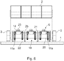
- Figs. 6-10 present a third advantageous embodiment of the wave energy recovery apparatus according to the invention.
- Fig. 6 another type of an arrangement according to the invention is presented in a side view and in a simplified and diagrammatic way.
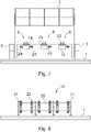
- Fig. 7 presents in a side view and in a simplified and diagrammatic way the reciprocating panel 2 with generators 14 according to the arrangement of Fig.6 .
- Fig. 8 presents in a side view and in a simplified and diagrammatic way the motionless lower part 19 of the arrangement according to Fig.6
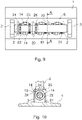
- Fig. 9 presents in a top view and in a simplified and diagrammatic way and partially cross-sectioned the wave recovery arrangement according to Fig.6
- Fig. 10 presents in a simplified and diagrammatic way the wave recovery arrangement according to Fig.6 seen cross-sectioned along the line A-A in Fig. 9 .
- the third embodiment of the wave energy recovery apparatus comprises a reciprocating hinged panel 2 that is substantially similar to the panel 2 presented in Fig. 1 .
- the panel is fitted at its ends with bearings that are in bearing housings 3 located at the ends of the panel 2.
- the bearing housings 3 are fastened to the base 1.
- the panel 2 has a downwards opening recess 2b that is almost as wide as the panel 2.
- the recess 2b makes room for the motionless lower part 19 of the arrangement.
- the panel 2 is able to make a reciprocating rotational motion partially around the motionless lower part 19.
- the arrangement according to third embodiment of the invention comprises six generators 14 that are fastened to the lower edge of the panel 2 with fastening elements 23.
- the generators 14 may be more or less than six but, however, always an even number, for example 2, 4, 8, 10, 12 or even more.
- the first half of the generators 14 are fastened to the first side of the panel 2 and the second half of the generators 14 are fastened to the second side of the same panel 2.
- each generator 14 comprises a gearwheel 24 of relatively small diameter and a one-way clutch mechanism 10, which both are mounted on the same axle.
- the one-way clutch mechanism 10 is operatively coupled between the generator axle and the gearwheel 24 axle and is arranged to allow the generator axle to rotate only to one direction, either clockwise or counterclockwise.
- the generators 14 on the first side of the panel 2 are in reverse direction compared to the generators 14 on the second side of the panel 2.
- gearwheels 24 of the generators 14 on the first side of the panel 2 are directed towards the second end of the panel 2
- gearwheels 24 of the generators 14 on the second side of the panel 2 are directed towards the first end of the panel 2. In that case, there is more room to arrange the gear assembly.
- Fig.7 only four generators 14 are presented in Fig.7 .
- Fig. 8 presents in a side view and in a simplified and diagrammatic way the motionless lower part 19 of the arrangement according to Fig.6 .
- the lower part 19 comprises a tubular shaft 20 that is supported and fastened to the base 1 with support legs 21.
- the tubular shaft 20 comprises on its outer circumference a number of motionless gear rims 22, in this case six substantially similar gear rims 22, one for each generator 14.
- the gear rims 22 are arranged to mesh with the gearwheels 24 of the generators.
- the gear rims 22 and the gearwheels 24 meshing with each other form a gear transmission 11a for the generators 14 of the third embodiment of the invention.
- the diameter of the gear rims 22 is relatively big compared to the diameter of the gearwheels 24. Therefore, the transmission ratio between the gear rim 22 and the gearwheel 24 is relatively great.
- the transmission ratio is greater than 10, suitably greater than 50 and preferably greater than 100. The greater the transmission ratio the faster the generators 14 rotate when the panel 2 makes its relatively slow reciprocating motion.
- Fig. 11-15 present a fourth advantageous embodiment of the wave energy recovery apparatus according to the invention.
- FIG. 11 yet another type of an arrangement according to the invention is presented in a side view and in a simplified and diagrammatic way.
- a protective housing 25 is removed from the first PTO unit 6.
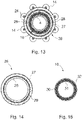
- Fig. 12 presents in a side view, enlarged, and in a simplified and diagrammatic way the first power take-off unit (PTO) 6 of the wave energy recovery apparatus according to Fig. 11 .
- Fig. 13 presents in a front view and in a simplified and diagrammatic way the power take-off unit (PTO) 6 of the wave energy recovery apparatus according to Fig. 11 .
- the figure is partially cross-sectioned so that only the tubular shaft 4 of the panel 2 is cross-sectioned.
- the actual PTO unit 6 is not necessarily cross-sectioned though it has cross-sectional lines.
- the cross-sectional lines are only presented to make the figure and its components easier to understand and to separate from each other.
- Fig. 14 presents in a front view and in a simplified and diagrammatic way a gear rim 26 of the PTO unit 6 of the wave energy recovery apparatus according to Fig. 11
- Fig. 15 presents in a front view and in a simplified and diagrammatic way a one-way clutch mechanism 10 of the PTO unit 6 of the wave energy recovery apparatus according to Fig. 11 .
- the fourth embodiment of the wave energy recovery apparatus comprises a reciprocating hinged panel 2 that is substantially like the panel 2 presented in Figs. 1 and 3 .
- the panel 2 has a hinged tubular shaft 4 that is fastened to the lower edge of the panel 2 and is arranged to rotate along with the panel 2.
- the tubular shaft 4 is fitted at its ends with bearings that are inside bearing housings 3 located at the ends of the panel 2.
- the bearing housings 3 are fastened to the base 1.
- the tubular shaft 4 acts as a pivot shaft for the reciprocating motion of the panel 2.
- the fourth embodiment of the invention comprises at least two PTO units 6, one at each end of the tubular shaft 4, which ends extend outwards from the bearing housings 3.
- Each PTO unit 6 comprises a one-way clutch mechanism 10, a gear rim 26 having a toothed outer circumference and a similar group of generators 14 coupled to the gear rim 26 through gearwheels 24 that mesh with the gear rim 26.
- the gear rim 26 and the gearwheels 24 meshing with each other form a gear transmission 11b for the generators 14 of the fourth embodiment of the invention.
- Each PTO unit 6 is coupled to the tubular shaft 4 through the one-way clutch mechanism 10 so that the one-way clutch mechanism 10 is operatively connected between the tubular shaft 4 and the inner circumference of the gear rim 26 of the gear transmission 11b.
- the gear rim 26 comprises an outer ring 27 with the toothed outer circumference, an inner ring 28 and an elastomer ring 29 between the outer and inner rings. All the rings are coaxial.
- the purpose of the elastomer ring 29 is to make the movements of the gear rim 26 softer and more flexible. Depending on local sea conditions the elastomer ring 29 may not be needed. In that case, neither the inner ring is needed.
- the gear rim 26 with or without the inner ring 28 is relatively big in its diameter and it is also relatively heavy. The mass is concentrated near the outer circumference of the gear rim 26, which means that the gear rim 26 has a high inertia.
- the gear rim 26 has properties of a flywheel and therefore it is arranged to act as a flywheel at the same time when it acts as the gear rim.
- the one-way clutch mechanism 10 can be any type of a one-way clutch, preferably the one-way clutch mechanism 10 is a so-called sprag clutch that has an outer ring 30, an inner ring 31 and an active ring 32 between the outer and inner ring.
- the active ring 32 comprises sprags that allow the rings 30 and 31 to rotate relative to each other into one direction but lock the rotation into the opposite direction.
- the one-way clutch mechanism 10 is fastened with its inner ring 31 onto the tubular shaft 4 to rotate along with the tubular shaft 4.
- the inner ring 31 rotates with the tubular shaft 4 at the same time, to the same direction and at the same speed.
- the outer ring 30 of the one-way clutch mechanism 10 is fastened to the inner circumference of the inner ring 28 of the gear rim 26 or directly to the inner circumference of the gear rim 26 if the elastomer ring 29 is not used.
- the one-way clutch mechanism 10 is arranged to allow the gear rim 26 to rotate only into one direction regardless of the direction of rotation of the tubular shaft 4.
- the diameter of the gear rim 26 is relatively big compared to the diameter of the gearwheels 24. Therefore, the transmission ratio between the gear rim 26 and the gearwheels 24 is relatively great.
- the transmission ratio is greater than 10, suitably greater than 50 and preferably greater than 100. The greater the transmission ratio the faster the generators 14 rotate when the panel 2 makes its relatively slow reciprocating motion.
- the arrangement according to fourth embodiment of the invention comprises two PTO units 6 with a group of generators 14 in each PTO unit 6.
- the generators 14 are presented eight in each PTO unit 6, but again, the generators 14 may be more or less than eight; however, always an even number, for example 2, 4, 6, 10, 12 or even more.
- the one-way clutch mechanism 10 of the first PTO unit 6 When the rotational movement of the panel 2 and the tubular shaft 4 is towards the first direction, say clockwise, the one-way clutch mechanism 10 of the first PTO unit 6 is in the working mode and the gear rim 26 of the first PTO unit 6 rotates the generators 14 of the first PTO unit 6, whereas the one-way clutch mechanism 10 of the second PTO unit 6 is in the free mode and the gear rim 26 of the second PTO unit 6 neither rotates nor decelerates the generators 14 of the second PTO unit 6 but, however, the rotation of the generators 14 of the second PTO unit 6 continues by the contribution of the flywheel effect of the gear rim 26.
- the arrangement comprises at least two PTO units 6 that each may comprise one or more generators 14.
- the generators are relatively small in size and arranged to be rotated fast by different types of gear transmissions. For example, when the generators 14 are rotated through a gear transmission the transmission ratio is greater than 10, suitably greater than 50 and preferably greater than 100. The greater the transmission ratio the faster the generators 14 rotate when the panel 2 makes its relatively slow reciprocating motion.
- a half of the generators 14 are rotated only to one direction and another half of the generators 14 are rotated only to the opposite direction.
- the first half of the generators 14 are rotated, for example, clockwise and the second half of the generators 14 are rotated counterclockwise, or vice versa.
- the first half of the generators 14 are rotated when the panel 2 makes its reciprocating movement to the first direction
- the second half of the generators 14 are rotated when the panel 2 makes its reciprocating movement to the second direction that is opposite to the movement of the first direction.
- This kind of operation is arranged by the use of one-way clutch mechanisms 10 that are placed between the movement of the panel 2 and the rotation of the axles of the generators 14.
Abstract
Description
- The present invention relates to a wave energy recovery apparatus with a power-take-off arrangement as defined in the preamble of
claim 1. - The wave energy recovery apparatus according to the invention is suited very well for instance to be used in connection with panels or flaps or essentially platelike wing elements, later called shorter only as panels, hinged with their lower edge to make a reciprocating movement caused by wave energy or tidal energy of seawater as shown for example in the US patent No.
US7131269 (B2 ). The wave energy or tidal energy collected is further converted underwater with a conversion unit for instance to electric energy. For the sake of simplicity, only the term wave energy is later mentioned when both the wave energy and the tidal energy of seawater are meant. - According to prior art there are various types of wave energy recovery systems where the arrangements include a base, and, for instance, one or more panels pivotally connected to the base to make a reciprocating or oscillating movement about a rotation axis or pivot axis in response to wave forces or tidal forces as shown for example in the US patent No.
US9279408 (B2 F11197918 - The PTO can also be placed inside the reciprocating structure of the wave energy recovery apparatus, for instance, inside the panel as shown for example in the US patent publication No.
US2016040647 A1 , or inside the tubular main shaft of the panel. - Commonly, in known wave energy converter systems it is difficult to efficiently transform the energy captured from the reciprocating movement of waves into electrical energy. For instance, the reciprocating movement of panels causes the rotors and axles of the electric generators to undergo a bi-directional rotational movement with a stop in connection with every reversing. As a consequence, the generators with components connected to them are prone to fatigue and further to breakages. In addition, controlling of the electric generators that make the reciprocating movement is complicated and difficult.
- For that reason, there have been several attempts to transform the reciprocating movement of the movable element in a unidirectional movement of the rotor of the generator. For instance, international patent publications
WO2006/118482 A1 ,WO2011/092555 A2 andWO2011/126451 A1 present different solutions to change the reciprocating movement caused by waves into a unidirectional movement of the rotor of the generator when recovering wave energy. - All these solutions of the WO publications mentioned above use at least two one-way clutches, freewheels or other anti-reverse mechanisms for each generator, which are continuously engaged and disengaged to ensure that the reciprocating movement caused by waves is changed to a unidirectional movement of the rotor of the generator. However, the continuous engagement and disengagement of the one-way clutches, freewheels or other anti-reverse mechanisms mentioned above cause mechanical wear and failures in the PTO systems. In addition, the PTO structures of the solutions of these WO publications are extremely complicated, which also cause the PTO structures to be prone to mechanical wear that reduces the lifetime of the solutions of these WO publications. Therefore, there is still a need for more efficient and/or more robust PTO systems.
- The object of the present invention is to eliminate the drawbacks described above and to achieve a reliable, compact, economical and efficient wave energy recovery apparatus with an improved power-take-off (PTO) arrangement in order to be able to capture a maximum amount of available wave or tidal energy and which apparatus is easily controllable. Another object of the present invention is to make the installation, maintenance and repairs of the wave energy conversion apparatus easy and fast, and to make it possible to easily disconnect/connect the electric generators from/to the other structure without disturbing the functions of the other structure. Thus, for example one generator can be removed and replaced with another generator without disturbing the whole system. The wave energy recovery apparatus with a power-take-off arrangement according to the invention is characterized by what is presented in the characterization part of
claim 1. Other embodiments of the invention are characterized by what is presented in the other claims. - An aspect of the invention is to provide a wave energy recovery apparatus with a power-take-off arrangement comprising at least a base, a reciprocating panel, two power-take-off (PTO) units with one or more generators to convert kinetic energy of waves or tidal currents to electricity, at least two gear transmissions and at least two one-way clutch mechanisms, all operatively connected between the panel and the generators. Advantageously, the panel is arranged to rotate a half of the generators when the panel is rotating into one direction and another half of the generators when the panel is rotating into the opposite direction. Advantageously, the direction of rotation of each generator is controlled with one one-way clutch mechanism, which one-way clutch mechanism is preferably arranged to allow the generator to have only one direction of rotation.
- The solution of the invention has significant advantages over the solutions of the prior art. The number of relatively small PTO units and/or electric generators make it possible to place several PTO units and/or generators along the shaft of the reciprocating panel. This allows a torque induced stress range to be more evenly distributed along the panel thus reducing the peak stress range induced by the PTO torque and thus increasing the fatigue life of the panel. That also allows the reduction in the size of the PTO components and thus the reduction in costs. The small size of the PTO units and/or generators also makes it possible to incorporate the PTO units and/or generators into the panel. With the help of a one-way clutch, such as a sprag clutch, one or more generators can be arranged to rotate to one direction only and another one or more generators can be arranged to rotate to the opposite direction only. Thus, a first half of the generators rotates all the time in one direction, i.e. clockwise, and a second half of the generators rotates all the time in opposite direction, i.e. counter clockwise. Yet one advantage is that the arrangement comprises at least two PTO units with generators. In that case, the PTO units can be taken separately to service and changed if necessary. Yet one advantage is that the PTO units can be installed on both sides of the panel.
- In the following, the invention will be described in detail by the aid of examples by referring to the attached simplified and diagrammatic drawings, wherein
- Fig. 1
- presents a simplified oblique top view of a wave energy recovery apparatus according to the invention equipped with a reciprocating panel,
- Fig. 2
- presents in a side view and in a simplified and diagrammatic way a lower part of the wave energy recovery apparatus according to
Fig. 1 a tubular shaft of the panel cross-sectioned, - Fig. 3
- presents a simplified oblique top view of another wave energy recovery apparatus according to the invention,
- Fig. 4
- presents in a side view and in a simplified and diagrammatic way a wave energy recovery apparatus according to
Fig. 3 with the lower part, comprising a tubular shaft, cross-sectioned, - Fig. 5
- presents in a side view, enlarged and in a simplified and diagrammatic way and cross-sectioned a power take-off unit (PTO) which can be used in the wave energy recovery apparatus according to the invention,
- Fig. 6
- presents in a side view and in a simplified and diagrammatic way yet another type of wave energy recovery apparatus according to the invention,
- Fig. 7
- presents in a side view and in a simplified and diagrammatic way the reciprocating panel with generators of the arrangement according to
Fig.6 , - Fig. 8
- presents in a side view and in a simplified and diagrammatic way the motionless lower part of the arrangement according to
Fig.6 , - Fig. 9
- presents in a top view and in a simplified and diagrammatic way and partially cross-sectioned the wave recovery arrangement according to
Fig.6 , - Fig. 10
- presents in a simplified and diagrammatic way the wave recovery arrangement according to
Fig.6 seen cross-sectioned along the line A-A inFig. 9 , - Fig. 11
- presents in a side view and in a simplified and diagrammatic way yet another type of wave energy recovery apparatus according to the invention, a protective housing removed from the first PTO unit,
- Fig. 12
- presents in a side view, enlarged, in a simplified and diagrammatic way and a power take-off unit (PTO) of the wave energy recovery apparatus according to
Fig. 11 without the protective housing, - Fig. 13
- presents in a front view and in a simplified and diagrammatic way and partially cross-sectioned the power take-off unit (PTO) of the wave energy recovery apparatus according to
Fig. 11 , - Fig. 14
- presents in a front view and in a simplified and diagrammatic way and a gear rim of the power take-off unit (PTO) of the wave energy recovery apparatus according to
Fig. 11 , and - Fig. 15
- presents in a front view and in a simplified and diagrammatic way and a one-way clutch mechanism of the power take-off unit (PTO) of the wave energy recovery apparatus according to
Fig. 11 . - The basic idea of the present invention is to achieve an arrangement, which comprises at least a
reciprocating panel 2 hinged with its lower edge, and at least two power take-off (PTO)units 6 with theirgenerators 14. Advantageously, thePTO units 6 or at least theirgenerators 14 are relatively small. In addition, eachgenerator 14 is arranged to rotate only to one direction, either clockwise or counterclockwise. Preferably, the arrangement comprises an even number ofgenerators 14 of which a half rotates clockwise, and another half rotates counterclockwise when seen from the same direction. At minimum the arrangement comprises twogenerators 14 but the number of generators can be also bigger. -
Figs. 1-2 present a first advantageous embodiment of the wave energy recovery apparatus according to the invention. InFig. 1 the wave energy recovery apparatus according to the invention equipped with a hingedreciprocating panel 2 is presented in a simplified oblique top view, and inFig. 2 the wave energy recovery apparatus according toFig. 1 is presented in a side view and in a simplified and diagrammatic way with atubular shaft 4 of thepanel 2 cross-sectioned. - The wave energy recovery apparatus comprises at least a
base 1, the hingedpanel 2 reciprocating about the center axis of its pivot shaft that comprises atubular shaft 4, fitted with bearings at both ends in bearinghousings 3 that are fastened to thebase 1. Onebearing housing 3 is at each end of thepanel 2. The power-take-off (PTO)units 6 are placed inside thetubular shaft 4, one at each end of thetubular shaft 4. Rotation axes 12 of the generators of thePTO units 6 are fitted with bearings betweensupport elements 7 in thebearing housings 3 and anintermediate support 3c that is inside and in the middle of thetubular shaft 4. Thefirst PTO unit 6 is fitted between thefirst support element 7 and the first side of theintermediate support 3c, and thesecond PTO unit 6 is fitted between thesecond support element 7 and the second side of theintermediate support 3c. Thepanel 2 is fastened to thetubular shaft 4. The reciprocating motion or shorter only the motion of thepanel 2 and thetubular shaft 4 is a back and forth rotating motion around the center axis of thetubular shaft 4. Preferably, the rotation angle of thepanel 2 is at maximum ±90° from the vertical position. Atransmission line 5 is used to transmit the produced electricity to further use. - The
reciprocating panel 2 oscillates on thebase 1 back and forth with the movement of seawater for recovering kinetic energy like wave energy of seawater. Thepanel 2 and thetubular shaft 4 rotate back and forth together simultaneously and at the same speed of rotation. At the production site thebase 1 is preferably mounted onto the bottom of the sea, but it can also be near the bottom supported by pillars. -
Figs. 3-4 present another advantageous embodiment of the wave energy recovery apparatus according to the invention. InFig. 3 the wave energy recovery apparatus according to the invention is presented in a simplified oblique top view, and inFig. 4 the wave energy recovery apparatus according toFig. 3 is presented in a side view and in a simplified and diagrammatic way, and the lower part that comprises atubular shaft 4 is cross-sectioned. - The wave energy recovery apparatus comprises at least a
base 1, a hingedpanel 2 reciprocating about the center axis of its pivot shaft that comprises two substantially coaxialtubular shafts 4, fitted with bearings at both ends in bearinghousings 3 that are fastened to thebase 1. Thepanel 2 is fastened to thetubular shafts 4. Onebearing housing 3 is at each end of thepanel 2 and thethird bearing housing 3 is in the middle of thepanel 2 where thepanel 2 has arecess 2a for the bearinghousing 3. The power-take-off (PTO)units 6 are placed inside thetubular shafts 4. The reciprocating motion or shorter only motion of thepanel 2 and thetubular shafts 4 is a back and forth rotating motion around the center axis of thetubular shafts 4. Atransmission line 5 is used to transmit the produced electricity to further use. - The
reciprocating panel 2 oscillates on thebase 1 back and forth with the movement of seawater for recovering kinetic energy like wave energy of seawater. Thepanel 2 and thetubular shafts 4 rotate back and forth together simultaneously and at the same speed of rotation. At the production site thebase 1 is preferably mounted onto the bottom of the sea, but it can also be near the bottom supported by pillars. - The embodiments according to
Figs. 1-4 comprise twocoaxial PTO units 6 that have been placed inside onetubular shaft 4 or twotubular shafts 4, onePTO unit 6 in eachshaft 4. Advantageously, the number ofPTO units 6 inside thetubular shafts 4 can be also bigger than two. Thus, thePTO units 6 can be inside their owntubular shafts 4 also 4, 6, 8, 10, 12 or even more but always an even number. -
Fig. 5 presents in a side view, enlarged and in a simplified, diagrammatic and a more detailed way and cross-sectioned a power take-off unit orshorter PTO unit 6 that can be used in the wave energy recovery apparatus according to the invention. The same kind ofPTO unit 6 can be used both the wave energy recovery apparatus accordingFig. 1 orFig. 3 . Only the bearing arrangement between the twoPTO units 6 differs depending on the case. - A
support element 7 with a circular cross-section is fastened inside thefirst bearing housing 3 so that thesupport element 7 extends with smaller circular crosssections towards themiddlemost bearing housing 3 in the middle of thepanel 2. Between the inner circumference of the bearinghousing 3 and the outer circumference of thesupport element 7 there is an annular groove for abearing 8 with which thetubular shaft 4 is fitted in the bearinghousing 3 at its first end. Correspondingly, themiddlemost bearing housing 3 of the embodiment ofFig. 3 has in its both sides anannular groove 3a for abearing 9 with which thetubular shafts 4 are fitted in themiddlemost bearing housing 3 at their second end. Arotation axle 12 of thegenerator 14 is fitted withbearings 13 at its both ends. At the first end of theaxle 12 thebearing 13 is in its recess in the center of thesupport element 7 and at the second end of theaxle 12 thebearing 13 is in itsrecess 3b in the center of theannular groove 3a for thebearing 9. Thus, all thebearings - On the first end of the
rotation axle 12 there is a speed changing gear system, such as agear transmission 11 to convert the slow motion of thepanel 2 andtubular shaft 4 to a fast speed of rotation of therotation axle 12. Preferably, thegear transmission 11 is a planetary transmission. Thegear transmission 11 is coupled to the slowly reciprocatingtubular shaft 4 through a one-wayclutch mechanism 10 so that therotation axle 12 rotates to one direction only, either clockwise or counterclockwise. In that case, the outer circumference of the one-wayclutch mechanism 10 is fastened to the inner circumference of thetubular shaft 4 and the inner circumference of the one-wayclutch mechanism 10 is fastened to the outer part of thegear transmission 11. Thus, the one-wayclutch mechanism 10 is operatively connected between thetubular shaft 4 and thegear transmission 11, whichgear transmission 11 is further operatively connected between the one-wayclutch mechanism 10 and therotation axle 12 of thegenerator 14. - On the middle part of the
rotation axle 12 there is arotor 16 of thegenerator 14. Astator 15 is axially at the same location and is fastened to the inner circumference of thetubular shaft 4. On the second end of therotation axle 12 there is aflywheel 18 that is fastened to therotation axle 12. Axially between thegenerator 14 and theflywheel 18 there is asupport flange 17 that is fastened to the inner circumference of thetubular shaft 4. Thesupport flange 17 has a bearing, preferably similar to thebearings 13 on which therotation axle 12 is fitted. - As mentioned earlier the advantageous embodiments of the wave energy recovery apparatus according to the invention comprises two
PTO units 6. For example, the embodiments ofFigs. 1 and3 advantageously comprises comprise twoPTO units 6.Fig. 5 presents thefirst PTO unit 6 of the two. Thesecond PTO unit 6 is otherwise similar to the first one but the second one is like a mirror image and thegenerator 14 inside thetubular shaft 4 is arranged to rotate to the opposite direction compared to thegenerator 14 of thefirst PTO unit 6. In that case, the one-wayclutch mechanism 10 of thesecond PTO unit 6 is arranged to work reversely compared to the one-wayclutch mechanism 10 of thefirst PTO unit 6, when seen at the same direction. - Thus, when the rotational movement of the
panel 2 and thetubular shaft 4 is towards the first direction, say clockwise, the one-wayclutch mechanism 10 of thefirst PTO unit 6 is in the working mode and thegear transmission 11 of thefirst PTO unit 6 rotates itsrotation axle 12 in the clockwise direction, whereas the one-wayclutch mechanism 10 of thesecond PTO unit 6 is in the free mode and thegear transmission 11 of thesecond PTO unit 6 neither rotates nor decelerates itsrotation axle 12. However, therotation axle 12 of thesecond PTO unit 6 continues its rotation by the contribution of theflywheel 18. - And, when the
panel 2 goes back and the rotational movement of thepanel 2 and thetubular shaft 4 is towards the second direction, say counterclockwise, the one-wayclutch mechanism 10 of thefirst PTO unit 6 is in the free mode and thegear transmission 11 of thefirst PTO unit 6 neither rotates nor decelerates itsrotation axle 12. But also now, therotation axle 12 of thefirst PTO unit 6 continues its rotation by the contribution of theflywheel 18. Whereas the one-wayclutch mechanism 10 of thesecond PTO unit 6 is in the working mode and thegear transmission 11 of thesecond PTO unit 6 rotates itsrotation axle 12 in the counterclockwise direction. And continuing so, therotation axle 12 of thefirst PTO unit 6 rotates always clockwise and therotation axle 12 of thesecond PTO unit 6 rotates always counterclockwise. The clockwise and counterclockwise directions are always seen from the same direction, for example from the first end of thepanel 2. - When the apparatus comprises only two
PTO units 6 thetubular shaft 4 can also be a continuous unbroken shaft with onePTO unit 6 at its both ends, as is presented inFigs 1 and2 . Then themiddlemost bearing housing 3c is totally inside thetubular shaft 4 and rotates with thetubular shaft 4. When the apparatus comprises more than twoPTO units 6 it is realistic that eachPTO unit 6 is inside its owntubular shaft 4. -
Figs. 6-10 present a third advantageous embodiment of the wave energy recovery apparatus according to the invention. InFig. 6 another type of an arrangement according to the invention is presented in a side view and in a simplified and diagrammatic way.Fig. 7 presents in a side view and in a simplified and diagrammatic way thereciprocating panel 2 withgenerators 14 according to the arrangement ofFig.6 .Fig. 8 presents in a side view and in a simplified and diagrammatic way the motionlesslower part 19 of the arrangement according toFig.6 , whereasFig. 9 presents in a top view and in a simplified and diagrammatic way and partially cross-sectioned the wave recovery arrangement according toFig.6 , andFig. 10 presents in a simplified and diagrammatic way the wave recovery arrangement according toFig.6 seen cross-sectioned along the line A-A inFig. 9 . - The third embodiment of the wave energy recovery apparatus according to the invention comprises a reciprocating hinged
panel 2 that is substantially similar to thepanel 2 presented inFig. 1 . The panel is fitted at its ends with bearings that are in bearinghousings 3 located at the ends of thepanel 2. The bearinghousings 3 are fastened to thebase 1. Thepanel 2 has a downwards openingrecess 2b that is almost as wide as thepanel 2. Therecess 2b makes room for the motionlesslower part 19 of the arrangement. Thus, thepanel 2 is able to make a reciprocating rotational motion partially around the motionlesslower part 19. - The arrangement according to third embodiment of the invention comprises six
generators 14 that are fastened to the lower edge of thepanel 2 withfastening elements 23. Again, thegenerators 14 may be more or less than six but, however, always an even number, for example 2, 4, 8, 10, 12 or even more. Preferably, the first half of thegenerators 14 are fastened to the first side of thepanel 2 and the second half of thegenerators 14 are fastened to the second side of thesame panel 2. - Advantageously, all the
generators 14 are substantially similar. In addition to characteristic components, eachgenerator 14 comprises agearwheel 24 of relatively small diameter and a one-wayclutch mechanism 10, which both are mounted on the same axle. The one-wayclutch mechanism 10 is operatively coupled between the generator axle and thegearwheel 24 axle and is arranged to allow the generator axle to rotate only to one direction, either clockwise or counterclockwise. In addition, thegenerators 14 on the first side of thepanel 2 are in reverse direction compared to thegenerators 14 on the second side of thepanel 2. Thus, whengearwheels 24 of thegenerators 14 on the first side of thepanel 2 are directed towards the second end of thepanel 2 thegearwheels 24 of thegenerators 14 on the second side of thepanel 2 are directed towards the first end of thepanel 2. In that case, there is more room to arrange the gear assembly. For the sake of clarity only fourgenerators 14 are presented inFig.7 . -
Fig. 8 presents in a side view and in a simplified and diagrammatic way the motionlesslower part 19 of the arrangement according toFig.6 . Thelower part 19 comprises atubular shaft 20 that is supported and fastened to thebase 1 withsupport legs 21. Thetubular shaft 20 comprises on its outer circumference a number of motionless gear rims 22, in this case six substantiallysimilar gear rims 22, one for eachgenerator 14. The gear rims 22 are arranged to mesh with thegearwheels 24 of the generators. The gear rims 22 and thegearwheels 24 meshing with each other form agear transmission 11a for thegenerators 14 of the third embodiment of the invention. - The diameter of the gear rims 22 is relatively big compared to the diameter of the
gearwheels 24. Therefore, the transmission ratio between thegear rim 22 and thegearwheel 24 is relatively great. For example, the transmission ratio is greater than 10, suitably greater than 50 and preferably greater than 100. The greater the transmission ratio the faster thegenerators 14 rotate when thepanel 2 makes its relatively slow reciprocating motion. -
Fig. 11-15 present a fourth advantageous embodiment of the wave energy recovery apparatus according to the invention. InFig. 11 yet another type of an arrangement according to the invention is presented in a side view and in a simplified and diagrammatic way. Aprotective housing 25 is removed from thefirst PTO unit 6.Fig. 12 presents in a side view, enlarged, and in a simplified and diagrammatic way the first power take-off unit (PTO) 6 of the wave energy recovery apparatus according toFig. 11 . WhereasFig. 13 presents in a front view and in a simplified and diagrammatic way the power take-off unit (PTO) 6 of the wave energy recovery apparatus according toFig. 11 . The figure is partially cross-sectioned so that only thetubular shaft 4 of thepanel 2 is cross-sectioned. Theactual PTO unit 6 is not necessarily cross-sectioned though it has cross-sectional lines. The cross-sectional lines are only presented to make the figure and its components easier to understand and to separate from each other. Correspondingly,Fig. 14 presents in a front view and in a simplified and diagrammatic way agear rim 26 of thePTO unit 6 of the wave energy recovery apparatus according toFig. 11 , and finallyFig. 15 presents in a front view and in a simplified and diagrammatic way a one-wayclutch mechanism 10 of thePTO unit 6 of the wave energy recovery apparatus according toFig. 11 . - The fourth embodiment of the wave energy recovery apparatus according to the invention comprises a reciprocating hinged
panel 2 that is substantially like thepanel 2 presented inFigs. 1 and3 . Thepanel 2 has a hingedtubular shaft 4 that is fastened to the lower edge of thepanel 2 and is arranged to rotate along with thepanel 2. Thetubular shaft 4 is fitted at its ends with bearings that are inside bearinghousings 3 located at the ends of thepanel 2. The bearinghousings 3 are fastened to thebase 1. Thetubular shaft 4 acts as a pivot shaft for the reciprocating motion of thepanel 2. - Preferably, the fourth embodiment of the invention comprises at least two
PTO units 6, one at each end of thetubular shaft 4, which ends extend outwards from the bearinghousings 3. EachPTO unit 6 comprises a one-wayclutch mechanism 10, agear rim 26 having a toothed outer circumference and a similar group ofgenerators 14 coupled to thegear rim 26 throughgearwheels 24 that mesh with thegear rim 26. Thegear rim 26 and thegearwheels 24 meshing with each other form agear transmission 11b for thegenerators 14 of the fourth embodiment of the invention. EachPTO unit 6 is coupled to thetubular shaft 4 through the one-wayclutch mechanism 10 so that the one-wayclutch mechanism 10 is operatively connected between thetubular shaft 4 and the inner circumference of the gear rim 26 of thegear transmission 11b. - The gear rim 26 comprises an
outer ring 27 with the toothed outer circumference, aninner ring 28 and anelastomer ring 29 between the outer and inner rings. All the rings are coaxial. The purpose of theelastomer ring 29 is to make the movements of thegear rim 26 softer and more flexible. Depending on local sea conditions theelastomer ring 29 may not be needed. In that case, neither the inner ring is needed. However, thegear rim 26 with or without theinner ring 28 is relatively big in its diameter and it is also relatively heavy. The mass is concentrated near the outer circumference of thegear rim 26, which means that thegear rim 26 has a high inertia. Thus, thegear rim 26 has properties of a flywheel and therefore it is arranged to act as a flywheel at the same time when it acts as the gear rim. - The one-way
clutch mechanism 10 can be any type of a one-way clutch, preferably the one-wayclutch mechanism 10 is a so-called sprag clutch that has anouter ring 30, aninner ring 31 and anactive ring 32 between the outer and inner ring. Theactive ring 32 comprises sprags that allow therings - The one-way
clutch mechanism 10 is fastened with itsinner ring 31 onto thetubular shaft 4 to rotate along with thetubular shaft 4. Theinner ring 31 rotates with thetubular shaft 4 at the same time, to the same direction and at the same speed. Theouter ring 30 of the one-wayclutch mechanism 10 is fastened to the inner circumference of theinner ring 28 of thegear rim 26 or directly to the inner circumference of thegear rim 26 if theelastomer ring 29 is not used. Thus, the one-wayclutch mechanism 10 is arranged to allow thegear rim 26 to rotate only into one direction regardless of the direction of rotation of thetubular shaft 4. - The diameter of the
gear rim 26 is relatively big compared to the diameter of thegearwheels 24. Therefore, the transmission ratio between thegear rim 26 and thegearwheels 24 is relatively great. For example, the transmission ratio is greater than 10, suitably greater than 50 and preferably greater than 100. The greater the transmission ratio the faster thegenerators 14 rotate when thepanel 2 makes its relatively slow reciprocating motion. - The arrangement according to fourth embodiment of the invention comprises two
PTO units 6 with a group ofgenerators 14 in eachPTO unit 6. Now, thegenerators 14 are presented eight in eachPTO unit 6, but again, thegenerators 14 may be more or less than eight; however, always an even number, for example 2, 4, 6, 10, 12 or even more. - When the rotational movement of the
panel 2 and thetubular shaft 4 is towards the first direction, say clockwise, the one-wayclutch mechanism 10 of thefirst PTO unit 6 is in the working mode and the gear rim 26 of thefirst PTO unit 6 rotates thegenerators 14 of thefirst PTO unit 6, whereas the one-wayclutch mechanism 10 of thesecond PTO unit 6 is in the free mode and the gear rim 26 of thesecond PTO unit 6 neither rotates nor decelerates thegenerators 14 of thesecond PTO unit 6 but, however, the rotation of thegenerators 14 of thesecond PTO unit 6 continues by the contribution of the flywheel effect of thegear rim 26. - And, when the
panel 2 goes back and the rotational movement of thepanel 2 and thetubular shaft 4 is towards the second direction, say counterclockwise, the one-wayclutch mechanism 10 of thefirst PTO unit 6 is in the free mode and the gear rim 26 of thefirst PTO unit 6 neither rotates nor decelerates thegenerators 14 of thefirst PTO unit 6. But also now, the rotation of thegenerators 14 of thefirst PTO unit 6 continues by the contribution of the flywheel effect of thegear rim 26, whereas the one-wayclutch mechanism 10 of thesecond PTO unit 6 is in the working mode and the gear rim 26 of thesecond PTO unit 6 rotates thegenerators 14 of thesecond PTO unit 6. - It is common to all the embodiments of the invention that the arrangement comprises at least two
PTO units 6 that each may comprise one ormore generators 14. Also, the generators are relatively small in size and arranged to be rotated fast by different types of gear transmissions. For example, when thegenerators 14 are rotated through a gear transmission the transmission ratio is greater than 10, suitably greater than 50 and preferably greater than 100. The greater the transmission ratio the faster thegenerators 14 rotate when thepanel 2 makes its relatively slow reciprocating motion. - Further in common is that a half of the
generators 14 are rotated only to one direction and another half of thegenerators 14 are rotated only to the opposite direction. In that case, seen from the same direction the first half of thegenerators 14 are rotated, for example, clockwise and the second half of thegenerators 14 are rotated counterclockwise, or vice versa. Thus, the first half of thegenerators 14 are rotated when thepanel 2 makes its reciprocating movement to the first direction and the second half of thegenerators 14 are rotated when thepanel 2 makes its reciprocating movement to the second direction that is opposite to the movement of the first direction. This kind of operation is arranged by the use of one-wayclutch mechanisms 10 that are placed between the movement of thepanel 2 and the rotation of the axles of thegenerators 14. - It is obvious to the person skilled in the art that the invention is not restricted to the examples described above but that it may be varied within the scope of the claims presented below. Thus, for example, the structure and positions of the PTO unit can be different from what is presented.
Claims (8)
- Wave energy recovery apparatus with a power-take-off arrangement comprising at least a base (1), a reciprocating panel (2), two power-take-off (PTO) units (6) each PTO unit comprising one or more generators (14) to convert kinetic energy of waves or tidal currents to electricity, at least two gear transmissions (11, 11a, 11b) and at least two one-way clutch mechanisms (10) where the gear transmissions (11, 11a, 11b) and one-way clutch mechanisms (10) are operatively connected between the panel (2) and the first gear wheel (11, 11a, 11b), and that the panel (2) is arranged to rotate a half of the gears and generators (14) when the panel (2) is rotating into one direction and another half of the gears and generators (14) when the panel (2) is rotating into the opposite direction, characterized in that the apparatus comprises a hinged tubular shaft (4) that is fastened to the lower edge of the panel (2) and is arranged to rotate along with the panel (2), and that the apparatus comprises two or more PTO units (6) coupled to the tubular shaft (4), each PTO unit (6) comprising a similar group of generators (14), a gear transmission (11b) for its generators (14) and a one-way clutch mechanism (10) operatively connected between the tubular shaft (4) and the gear transmission (11b).
- Wave energy recovery apparatus according to claim 1, characterized in that the direction of rotation of each gear mechanism is controlled with one one-way clutch mechanism (10).
- Wave energy recovery apparatus according to claim 1 or 2, characterized in that the one-way clutch mechanism (10) is arranged to allow the related gear mechanism (11, 11a, 11b) to have only one direction of rotation and full rotation of motion of the transmission mechanism such that all surfaces of the transmission mechanism experience equal wear.
- Wave energy recovery apparatus according to claim 1, 2 or 3, characterized in that each gear transmission (11, 11a, 11b) is equipped with a transmission ratio effecting between the rotational movement of the panel (2) and the rotation axle of the generator (14), which transmission ratio is greater than 10, suitably greater than 50 and preferably greater than 100.
- Wave energy recovery apparatus according to any of the claims above, characterized in that the PTO units (6) are equipped with an elastomer (29) and flywheel properties to maintain the rotation of the axle of the generator (14) when the generator (14) is rotating freely.
- Wave energy recovery apparatus according to any of the claims above, characterized in that the gear transmission (11b) comprises a gear rim (26) meshing with gearwheels (24) of the generators (14) that are radially placed on the outer circumference of the gear rim (26).
- Wave energy recovery apparatus according to any of the claims above, characterized in that the one-way clutch mechanism (10) operatively connected between the tubular shaft (4) and the gear transmission (11b).
- Wave energy recovery apparatus according to any of the claims above, characterized in that the one-way clutch mechanism (10) is a sprag clutch.
Priority Applications (1)
| Application Number | Priority Date | Filing Date | Title |
|---|---|---|---|
| EP22189253.2A EP4112918A1 (en) | 2018-05-30 | 2018-05-30 | Wave energy recovery apparatus with power-take-off arrangement |
Applications Claiming Priority (3)
| Application Number | Priority Date | Filing Date | Title |
|---|---|---|---|
| PCT/FI2018/050407 WO2019229290A1 (en) | 2018-05-30 | 2018-05-30 | Wave energy recovery apparatus with power-take-off arrangement |
| EP22189253.2A EP4112918A1 (en) | 2018-05-30 | 2018-05-30 | Wave energy recovery apparatus with power-take-off arrangement |
| EP18920566.9A EP3803100B1 (en) | 2018-05-30 | 2018-05-30 | Wave energy recovery apparatus with power-take-off arrangement |
Related Parent Applications (2)
| Application Number | Title | Priority Date | Filing Date |
|---|---|---|---|
| EP18920566.9A Division-Into EP3803100B1 (en) | 2018-05-30 | 2018-05-30 | Wave energy recovery apparatus with power-take-off arrangement |
| EP18920566.9A Division EP3803100B1 (en) | 2018-05-30 | 2018-05-30 | Wave energy recovery apparatus with power-take-off arrangement |
Publications (1)
| Publication Number | Publication Date |
|---|---|
| EP4112918A1 true EP4112918A1 (en) | 2023-01-04 |
Family
ID=68697867
Family Applications (3)
| Application Number | Title | Priority Date | Filing Date |
|---|---|---|---|
| EP22189253.2A Pending EP4112918A1 (en) | 2018-05-30 | 2018-05-30 | Wave energy recovery apparatus with power-take-off arrangement |
| EP22189219.3A Pending EP4112917A1 (en) | 2018-05-30 | 2018-05-30 | Wave energy recovery apparatus with power-take-off arrangement |
| EP18920566.9A Active EP3803100B1 (en) | 2018-05-30 | 2018-05-30 | Wave energy recovery apparatus with power-take-off arrangement |
Family Applications After (2)
| Application Number | Title | Priority Date | Filing Date |
|---|---|---|---|
| EP22189219.3A Pending EP4112917A1 (en) | 2018-05-30 | 2018-05-30 | Wave energy recovery apparatus with power-take-off arrangement |
| EP18920566.9A Active EP3803100B1 (en) | 2018-05-30 | 2018-05-30 | Wave energy recovery apparatus with power-take-off arrangement |
Country Status (4)
| Country | Link |
|---|---|
| US (3) | US11493016B2 (en) |
| EP (3) | EP4112918A1 (en) |
| CN (3) | CN112400059B (en) |
| WO (1) | WO2019229290A1 (en) |
Families Citing this family (2)
| Publication number | Priority date | Publication date | Assignee | Title |
|---|---|---|---|---|
| CN111022242B (en) * | 2019-12-23 | 2021-04-02 | 武汉理工大学 | Power generation device comprehensively utilizing wave energy and ocean current energy |
| WO2021205056A1 (en) * | 2020-04-07 | 2021-10-14 | Aw-Energy Oy | Coupling arrangement in a wave energy recovery apparatus |
Citations (12)
| Publication number | Priority date | Publication date | Assignee | Title |
|---|---|---|---|---|
| US1925742A (en) * | 1932-04-21 | 1933-09-05 | Robert F Bamber | Wave motor |
| US7131269B2 (en) | 2001-10-26 | 2006-11-07 | Aw-Energy Oy | Process and an apparatus for utilizing wave energy |
| WO2006118482A1 (en) | 2005-05-02 | 2006-11-09 | Martifer Energia, Equipamentos Para Energia, S.A. | Energy conversion/inversion system |
| US20090051168A1 (en) * | 2007-08-23 | 2009-02-26 | Tetsuhiko Fujisato | Gravity wave power generation apparatus |
| FI119791B (en) | 2007-02-15 | 2009-03-13 | Aw Energy Oy | linear generator |
| WO2011092555A2 (en) | 2010-01-28 | 2011-08-04 | Resnova S.R.L. | A device for generating electric energy from the wave-motion |
| WO2011126451A1 (en) | 2010-04-07 | 2011-10-13 | Ocean Harvesting Technologies Ab | Wave energy converter and transmission |
| WO2013188397A1 (en) * | 2012-06-12 | 2013-12-19 | Resolute Marine Energy, Inc. | Linear array of wave-energy converters |
| WO2015082754A1 (en) * | 2013-12-05 | 2015-06-11 | Aw-Energy Oy | Wave energy conversion apparatus |
| WO2015177400A1 (en) * | 2014-05-22 | 2015-11-26 | Aw-Energy Oy | Energy transfer arrangement of a wave energy recovery apparatus |
| US20160040647A1 (en) | 2013-04-05 | 2016-02-11 | Aw-Energy Oy | Submersible wave energy conversion unit |
| US9279408B2 (en) | 2010-03-31 | 2016-03-08 | Aw-Energy Oy | Wave energy recovery system |
Family Cites Families (12)
| Publication number | Priority date | Publication date | Assignee | Title |
|---|---|---|---|---|
| KR200400674Y1 (en) | 2005-08-23 | 2005-11-08 | 현 용 이 | Ware activated generator |
| KR200406674Y1 (en) | 2005-09-20 | 2006-01-24 | 공현식 | The emulation equipment for input and output device of server or PC with the notebook computer. |
| GB0608128D0 (en) | 2006-04-25 | 2006-06-07 | Mccague James | Movement and power generation apparatus |
| US9551125B2 (en) * | 2009-03-26 | 2017-01-24 | Aw-Energy Oy | Method for installing and servicing an apparatus recovering the kinetic energy of water, and an apparatus recovering the kinetic energy of water |
| US9528900B2 (en) * | 2009-09-19 | 2016-12-27 | Bruce Gregory | Balanced and eccentric mass compact pendulum with dynamic tuning |
| US7964984B2 (en) * | 2010-04-01 | 2011-06-21 | Saavedra John A | Electric power generator utilizing intermittent wind |
| WO2012053899A1 (en) | 2010-10-21 | 2012-04-26 | Langlee Wave Power As | Wave power device with generator |
| US8745981B1 (en) * | 2013-10-10 | 2014-06-10 | John Clark Hanna | Ocean powered take-off for multiple rotary drives |
| MX2016009032A (en) * | 2014-01-08 | 2018-02-23 | Aw Energy Oy | Surface level follow-up arrangement for a wave energy recovery system. |
| EP3175111B1 (en) * | 2014-06-18 | 2019-08-07 | AW-Energy Oy | Wave energy recovery apparatus with an energy transfer arrangement |
| EP3359806A4 (en) | 2015-10-05 | 2019-07-24 | Rohrer Technologies, Inc. | Multi mode wave energy converter with elongated wave front parallel float having integral lower shoaling extension |
| GB2565927B (en) * | 2016-04-08 | 2021-08-25 | Aw Energy Oy | Arrangement in a wave energy recovery apparatus and method for operating a wave energy recovery apparatus |
-
2018
- 2018-05-30 CN CN201880095221.8A patent/CN112400059B/en active Active
- 2018-05-30 CN CN202211417040.7A patent/CN115638076A/en active Pending
- 2018-05-30 WO PCT/FI2018/050407 patent/WO2019229290A1/en active Search and Examination
- 2018-05-30 EP EP22189253.2A patent/EP4112918A1/en active Pending
- 2018-05-30 CN CN202211417160.7A patent/CN115788750A/en active Pending
- 2018-05-30 EP EP22189219.3A patent/EP4112917A1/en active Pending
- 2018-05-30 US US17/059,846 patent/US11493016B2/en active Active
- 2018-05-30 EP EP18920566.9A patent/EP3803100B1/en active Active
-
2022
- 2022-08-17 US US17/889,888 patent/US11698051B2/en active Active
- 2022-08-17 US US17/889,839 patent/US11719218B2/en active Active
Patent Citations (12)
| Publication number | Priority date | Publication date | Assignee | Title |
|---|---|---|---|---|
| US1925742A (en) * | 1932-04-21 | 1933-09-05 | Robert F Bamber | Wave motor |
| US7131269B2 (en) | 2001-10-26 | 2006-11-07 | Aw-Energy Oy | Process and an apparatus for utilizing wave energy |
| WO2006118482A1 (en) | 2005-05-02 | 2006-11-09 | Martifer Energia, Equipamentos Para Energia, S.A. | Energy conversion/inversion system |
| FI119791B (en) | 2007-02-15 | 2009-03-13 | Aw Energy Oy | linear generator |
| US20090051168A1 (en) * | 2007-08-23 | 2009-02-26 | Tetsuhiko Fujisato | Gravity wave power generation apparatus |
| WO2011092555A2 (en) | 2010-01-28 | 2011-08-04 | Resnova S.R.L. | A device for generating electric energy from the wave-motion |
| US9279408B2 (en) | 2010-03-31 | 2016-03-08 | Aw-Energy Oy | Wave energy recovery system |
| WO2011126451A1 (en) | 2010-04-07 | 2011-10-13 | Ocean Harvesting Technologies Ab | Wave energy converter and transmission |
| WO2013188397A1 (en) * | 2012-06-12 | 2013-12-19 | Resolute Marine Energy, Inc. | Linear array of wave-energy converters |
| US20160040647A1 (en) | 2013-04-05 | 2016-02-11 | Aw-Energy Oy | Submersible wave energy conversion unit |
| WO2015082754A1 (en) * | 2013-12-05 | 2015-06-11 | Aw-Energy Oy | Wave energy conversion apparatus |
| WO2015177400A1 (en) * | 2014-05-22 | 2015-11-26 | Aw-Energy Oy | Energy transfer arrangement of a wave energy recovery apparatus |
Also Published As
| Publication number | Publication date |
|---|---|
| US20220389899A1 (en) | 2022-12-08 |
| US11698051B2 (en) | 2023-07-11 |
| CN115638076A (en) | 2023-01-24 |
| US20220389898A1 (en) | 2022-12-08 |
| US11493016B2 (en) | 2022-11-08 |
| EP3803100B1 (en) | 2024-01-03 |
| CN112400059B (en) | 2023-02-28 |
| EP3803100A4 (en) | 2022-01-05 |
| CN112400059A (en) | 2021-02-23 |
| EP4112917A1 (en) | 2023-01-04 |
| US20210222666A1 (en) | 2021-07-22 |
| WO2019229290A1 (en) | 2019-12-05 |
| CN115788750A (en) | 2023-03-14 |
| EP3803100C0 (en) | 2024-01-03 |
| EP3803100A1 (en) | 2021-04-14 |
| US11719218B2 (en) | 2023-08-08 |
Similar Documents
| Publication | Publication Date | Title |
|---|---|---|
| US11698051B2 (en) | Wave energy recovery apparatus with power-take-off arrangement | |
| US8198749B2 (en) | Wind turbine generator | |
| KR100752510B1 (en) | Wind energy converter with single main bearing | |
| US9903348B2 (en) | Drive device for a wind turbine | |
| US8529397B2 (en) | Gear system for a wind turbine | |
| EP2525090B1 (en) | Wind turbine nacelle | |
| EP2955412B1 (en) | Rotorcraft and planetary gear systems | |
| JP6188718B2 (en) | transmission | |
| CN102287333A (en) | Gear set, wind turbine incorporating such a gear set and method of servicing a wind turbine | |
| US2168164A (en) | Speed reducer | |
| WO2009044159A1 (en) | A transmission system for power generation | |
| CA2999459C (en) | Radial magnetic cycloid gear assemblies, and related systems and methods | |
| JP4909578B2 (en) | Windmill drive | |
| CN108880091A (en) | A kind of Two axle drive harmonic wave reducing motor | |
| CA2795391A1 (en) | Wind energy installation azimuth or pitch drive | |
| US20160369766A1 (en) | Wave energy conversion apparatus | |
| EP3480508B1 (en) | Lubrication system for a main bearing of a wind turbine | |
| KR101074694B1 (en) | Wind turbine gearbox with rotating housing | |
| CN214499976U (en) | Overrunning clutch system | |
| KR100723937B1 (en) | Power transmission apparatus for helicopter | |
| CN112709804A (en) | Overrunning clutch system | |
| EP2884102B1 (en) | Gearbox for wind power plant | |
| AU2006272437B2 (en) | A blade pitch control mechanism | |
| CN117366184A (en) | High-efficiency horizontal opposite power device | |
| TR202008564U5 (en) | CONSTRUCTION OF A VERSATILE POWER TRAINED REDUCER |
Legal Events
| Date | Code | Title | Description |
|---|---|---|---|
| PUAI | Public reference made under article 153(3) epc to a published international application that has entered the european phase |
Free format text: ORIGINAL CODE: 0009012 |
|
| STAA | Information on the status of an ep patent application or granted ep patent |
Free format text: STATUS: THE APPLICATION HAS BEEN PUBLISHED |
|
| AC | Divisional application: reference to earlier application |
Ref document number: 3803100 Country of ref document: EP Kind code of ref document: P |
|
| AK | Designated contracting states |
Kind code of ref document: A1 Designated state(s): AL AT BE BG CH CY CZ DE DK EE ES FI FR GB GR HR HU IE IS IT LI LT LU LV MC MK MT NL NO PL PT RO RS SE SI SK SM TR |
|
| STAA | Information on the status of an ep patent application or granted ep patent |
Free format text: STATUS: REQUEST FOR EXAMINATION WAS MADE |
|
| 17P | Request for examination filed |
Effective date: 20230630 |
|
| RBV | Designated contracting states (corrected) |
Designated state(s): AL AT BE BG CH CY CZ DE DK EE ES FI FR GB GR HR HU IE IS IT LI LT LU LV MC MK MT NL NO PL PT RO RS SE SI SK SM TR |
|
| GRAP | Despatch of communication of intention to grant a patent |
Free format text: ORIGINAL CODE: EPIDOSNIGR1 |
|
| STAA | Information on the status of an ep patent application or granted ep patent |
Free format text: STATUS: GRANT OF PATENT IS INTENDED |
|
| INTG | Intention to grant announced |
Effective date: 20240122 |