EP4112468B1 - Inflatable separation area for a vehicle interior - Google Patents
Inflatable separation area for a vehicle interior Download PDFInfo
- Publication number
- EP4112468B1 EP4112468B1 EP21183563.2A EP21183563A EP4112468B1 EP 4112468 B1 EP4112468 B1 EP 4112468B1 EP 21183563 A EP21183563 A EP 21183563A EP 4112468 B1 EP4112468 B1 EP 4112468B1
- Authority
- EP
- European Patent Office
- Prior art keywords
- inflatable
- separating region
- vehicle interior
- tubes
- designed
- Prior art date
- Legal status (The legal status is an assumption and is not a legal conclusion. Google has not performed a legal analysis and makes no representation as to the accuracy of the status listed.)
- Active
Links
- 238000000926 separation method Methods 0.000 title description 66
- 239000012528 membrane Substances 0.000 claims description 37
- 239000000463 material Substances 0.000 claims description 11
- 229920001169 thermoplastic Polymers 0.000 claims description 4
- 239000004416 thermosoftening plastic Substances 0.000 claims description 4
- 230000006978 adaptation Effects 0.000 claims 1
- 238000011161 development Methods 0.000 description 17
- 230000018109 developmental process Effects 0.000 description 17
- 238000005192 partition Methods 0.000 description 9
- 208000015181 infectious disease Diseases 0.000 description 7
- 230000001681 protective effect Effects 0.000 description 7
- 230000008901 benefit Effects 0.000 description 6
- 239000003063 flame retardant Substances 0.000 description 4
- 238000009434 installation Methods 0.000 description 4
- 244000052769 pathogen Species 0.000 description 4
- RNFJDJUURJAICM-UHFFFAOYSA-N 2,2,4,4,6,6-hexaphenoxy-1,3,5-triaza-2$l^{5},4$l^{5},6$l^{5}-triphosphacyclohexa-1,3,5-triene Chemical compound N=1P(OC=2C=CC=CC=2)(OC=2C=CC=CC=2)=NP(OC=2C=CC=CC=2)(OC=2C=CC=CC=2)=NP=1(OC=1C=CC=CC=1)OC1=CC=CC=C1 RNFJDJUURJAICM-UHFFFAOYSA-N 0.000 description 3
- 208000035473 Communicable disease Diseases 0.000 description 3
- 238000013459 approach Methods 0.000 description 3
- 238000010276 construction Methods 0.000 description 3
- 238000009423 ventilation Methods 0.000 description 3
- 238000013461 design Methods 0.000 description 2
- 230000007613 environmental effect Effects 0.000 description 2
- 230000002458 infectious effect Effects 0.000 description 2
- 238000002955 isolation Methods 0.000 description 2
- 239000000126 substance Substances 0.000 description 2
- 239000012780 transparent material Substances 0.000 description 2
- RRHGJUQNOFWUDK-UHFFFAOYSA-N Isoprene Chemical compound CC(=C)C=C RRHGJUQNOFWUDK-UHFFFAOYSA-N 0.000 description 1
- VVQNEPGJFQJSBK-UHFFFAOYSA-N Methyl methacrylate Chemical compound COC(=O)C(C)=C VVQNEPGJFQJSBK-UHFFFAOYSA-N 0.000 description 1
- 229920005372 Plexiglas® Polymers 0.000 description 1
- 239000004952 Polyamide Substances 0.000 description 1
- 239000004721 Polyphenylene oxide Substances 0.000 description 1
- 239000006093 Sitall Substances 0.000 description 1
- 241000700605 Viruses Species 0.000 description 1
- 208000027418 Wounds and injury Diseases 0.000 description 1
- 238000005299 abrasion Methods 0.000 description 1
- 239000000853 adhesive Substances 0.000 description 1
- 230000001070 adhesive effect Effects 0.000 description 1
- 239000004760 aramid Substances 0.000 description 1
- 229920006231 aramid fiber Polymers 0.000 description 1
- QVGXLLKOCUKJST-UHFFFAOYSA-N atomic oxygen Chemical compound [O] QVGXLLKOCUKJST-UHFFFAOYSA-N 0.000 description 1
- 230000004888 barrier function Effects 0.000 description 1
- 238000005452 bending Methods 0.000 description 1
- 230000004071 biological effect Effects 0.000 description 1
- 230000008859 change Effects 0.000 description 1
- 238000012937 correction Methods 0.000 description 1
- 230000006378 damage Effects 0.000 description 1
- 201000010099 disease Diseases 0.000 description 1
- 208000037265 diseases, disorders, signs and symptoms Diseases 0.000 description 1
- 229920001971 elastomer Polymers 0.000 description 1
- 238000005516 engineering process Methods 0.000 description 1
- 230000009970 fire resistant effect Effects 0.000 description 1
- 239000007789 gas Substances 0.000 description 1
- 239000011521 glass Substances 0.000 description 1
- 208000014674 injury Diseases 0.000 description 1
- 238000004519 manufacturing process Methods 0.000 description 1
- 239000000203 mixture Substances 0.000 description 1
- 238000012986 modification Methods 0.000 description 1
- 230000004048 modification Effects 0.000 description 1
- JHJNPOSPVGRIAN-SFHVURJKSA-N n-[3-[(1s)-1-[[6-(3,4-dimethoxyphenyl)pyrazin-2-yl]amino]ethyl]phenyl]-5-methylpyridine-3-carboxamide Chemical compound C1=C(OC)C(OC)=CC=C1C1=CN=CC(N[C@@H](C)C=2C=C(NC(=O)C=3C=C(C)C=NC=3)C=CC=2)=N1 JHJNPOSPVGRIAN-SFHVURJKSA-N 0.000 description 1
- 230000007935 neutral effect Effects 0.000 description 1
- 239000001301 oxygen Substances 0.000 description 1
- 229910052760 oxygen Inorganic materials 0.000 description 1
- 239000004033 plastic Substances 0.000 description 1
- 229920003023 plastic Polymers 0.000 description 1
- 229920002647 polyamide Polymers 0.000 description 1
- 229920000728 polyester Polymers 0.000 description 1
- 229920000570 polyether Polymers 0.000 description 1
- 229920001195 polyisoprene Polymers 0.000 description 1
- 229920000642 polymer Polymers 0.000 description 1
- 229920006264 polyurethane film Polymers 0.000 description 1
- 238000012545 processing Methods 0.000 description 1
- 230000001105 regulatory effect Effects 0.000 description 1
- 230000000241 respiratory effect Effects 0.000 description 1
- 230000000284 resting effect Effects 0.000 description 1
- 239000005060 rubber Substances 0.000 description 1
- 230000007480 spreading Effects 0.000 description 1
- 208000024891 symptom Diseases 0.000 description 1
Images


Classifications
-
- B—PERFORMING OPERATIONS; TRANSPORTING
- B64—AIRCRAFT; AVIATION; COSMONAUTICS
- B64D—EQUIPMENT FOR FITTING IN OR TO AIRCRAFT; FLIGHT SUITS; PARACHUTES; ARRANGEMENT OR MOUNTING OF POWER PLANTS OR PROPULSION TRANSMISSIONS IN AIRCRAFT
- B64D11/00—Passenger or crew accommodation; Flight-deck installations not otherwise provided for
- B64D11/06—Arrangements of seats, or adaptations or details specially adapted for aircraft seats
- B64D11/0606—Arrangements of seats, or adaptations or details specially adapted for aircraft seats with privacy shells, screens, separators or the like
-
- B—PERFORMING OPERATIONS; TRANSPORTING
- B64—AIRCRAFT; AVIATION; COSMONAUTICS
- B64D—EQUIPMENT FOR FITTING IN OR TO AIRCRAFT; FLIGHT SUITS; PARACHUTES; ARRANGEMENT OR MOUNTING OF POWER PLANTS OR PROPULSION TRANSMISSIONS IN AIRCRAFT
- B64D11/00—Passenger or crew accommodation; Flight-deck installations not otherwise provided for
- B64D11/0023—Movable or removable cabin dividers, e.g. for class separation
-
- B—PERFORMING OPERATIONS; TRANSPORTING
- B60—VEHICLES IN GENERAL
- B60N—SEATS SPECIALLY ADAPTED FOR VEHICLES; VEHICLE PASSENGER ACCOMMODATION NOT OTHERWISE PROVIDED FOR
- B60N2/00—Seats specially adapted for vehicles; Arrangement or mounting of seats in vehicles
- B60N2/90—Details or parts not otherwise provided for
- B60N2/91—Panels between front seats
Definitions
- the present invention relates to an inflatable partition area for a vehicle interior, in particular for a passenger cabin of an aircraft.
- the publication EP 3 272 643 A1 an inflatable partition for an aircraft, which in a passenger cabin can be installed to divide the room into different sections or areas.
- the publications EP 2 139 764 B1 and EP 2 554 477 B1 a sleeping berth with plate-shaped air chambers that form a self-supporting wall structure with side walls and ceiling, whereby the air chambers are enclosed by flexible flat material and have flexible webs in their interior to stabilize an external shape.
- the sleeping berth has a base shell with upright wall attachments onto which the wall structure can be subsequently attached.
- the publication also describes US10,888,479 B1 a biosafety booth for protecting the occupants of a vehicle from pathogens.
- the biosafety booth comprises a rigid or flexible protective cover element made of a durable and possibly fire-resistant material, e.g. glass, plexiglass or plastic, which forms a three-dimensional structure that is installed inside the vehicle and isolates one or more occupants of the biosafety booth from other occupants of the vehicle.
- a plurality of connecting elements are attached to the protective cover element, by means of which the protective cover element is fastened inside the vehicle.
- the protective cover element comprises air circulation openings for connection to an air filter device and an entrance/exit element for entering or leaving the biosafety booth through the protective cover element, wherein the entrance/exit element can have a zipper, a Velcro fastener or another suitable closure system.
- the present invention is based on the object of providing improved weight-saving solutions for separating limited cabin areas of aircraft that can be assembled and dismantled as easily and quickly as possible, even during operation.
- One idea underlying the present invention is to create a separated area for a vehicle interior that can be set up and dismantled quickly and easily by combining inflatable flexible tubes as support structures with thin flexible wall membranes that separate an interior of the separation area from the vehicle interior.
- the tubes serve as a supporting or load-bearing framework/skeleton, comparable to the tent poles of a tent, and at the same time define an outer contour of the area to be separated.
- the wall membranes provide the actual Separation of the interior space created in this way from the vehicle interior, in particular in the horizontal direction.
- the hoses can be fitted with one or more valves, through which the system can be inflated at a suitable position using an air pump, a bellows, a gas cartridge and/or a compressor.
- an air pump e.g. a pump that can provide compressed air at short notice
- systems already on board the vehicle that can provide compressed air at short notice can also be used for this purpose, e.g. an air treatment system and/or an aircraft compressor system.
- the hoses are sufficiently inflated, they stretch the wall membranes between them, which then form the walls of the separation area. No other special tools or aids are necessarily required for installation.
- the specific installation position can be selected particularly flexibly, even at short notice, depending on the interior design of the vehicle.
- the separation cabin or cell created in this way can be used for a wide variety of purposes inside the vehicle, with the simple construction allowing the system to be set up and/or dismantled at very short notice while the vehicle is in operation.
- the separation area When the separation area is not in use, it can be folded up and stowed away to save space.
- This takes advantage of the fact that the system can be constructed in a particularly weight-saving manner by using suitable thin materials for the flexible material of the hoses and wall membranes, which can also meet the corresponding safety requirements in terms of flammability, age resistance, tear resistance, environmental compatibility, etc.
- the system can also be used several times as required.
- the separation area can be set up on board an aircraft that is already in the air in order to isolate one or more passengers from the other passengers, e.g. in the event of a medical emergency, a highly contagious infection or the like. It is understood, however, that an inflatable separation area within the meaning of the invention can be used not only as a protective measure for medical or infectious disease applications. Furthermore, the invention can be used to create short-term or permanent rest areas in a passenger cabin, either for passengers or for the cabin crew. Depending on the specific application, the wall membranes of the shell can be transparent or more or less opaque.
- the separation area can be designed to be open at the top and bottom when inflated.
- the separation area can only be surrounded by the wall membranes on all horizontal sides and can rest on a floor of the vehicle interior. A remaining opening at the top can be used, for example, to supply air. It can also be provided that the separation area fits precisely at the top and bottom with a floor and a ceiling of the vehicle interior.
- the separation area is not closed on all horizontal sides, but only has wall membranes on those sides that are aligned into the vehicle interior and are not already are limited by the interior walls of the vehicle interior anyway.
- an exterior wall of the vehicle could not be covered by the wall membranes and these could only be provided on the aisle side and to the front and rear.
- the supporting structure and the shell can be designed to close the separating area at the top and bottom with the vehicle interior at least in some areas.
- the partition area can thus sit all around on the floor of the vehicle interior and abut against a ceiling without leaving an opening (at least at the edge) to the vehicle interior.
- air can be supplied to the partition area, for example, via air slots or the like arranged at the top and bottom (but in principle also at the sides) and let into the wall membranes.
- the air can be introduced via air outlets in a ceiling of the vehicle interior above the partition area and let out again via corresponding air outlets in the floor of the vehicle interior.
- the partition area does not completely close off from the vehicle interior at the top and/or bottom, but that ventilation slots remain through which the partition area remains connected to the vehicle interior in an air-permeable manner.
- ventilation elements can be integrated into the supporting structure and/or the shell of the partition area.
- At least three of the tubes can be designed as essentially vertical struts. Additional tubes can serve as cross connections for the struts.
- the separation area can have a rectangular floor plan, with four essentially vertically running hoses forming outer edges of the separation area and these being held together at an upper end by four transversely running hoses.
- four essentially vertically running hoses forming outer edges of the separation area and these being held together at an upper end by four transversely running hoses.
- more complex external geometries and/or hose arrangements are also possible.
- three vertically running hoses can be connected as outer edges of the separation area at an upper end to three corners of a square formed by four transversely running hoses.
- the stability of this tripod-like arrangement can be further improved by, for example, providing a fastening element at an upper end, particularly in the area of the "open edge" where there is no vertical hose and it is fixed there, for example, to a wall and/or deck of the vehicle interior.
- At least a portion of the hoses can be kinked and/or curved to adapt to an inner contour of the vehicle interior.
- the outer contour of the separation area defined by the hoses can thus conform more or less precisely to the inner contour of the vehicle interior. On the one hand, this allows the available space to be used optimally. On the other hand, the separation area can be supported and stabilized in a particularly advantageous manner by inner walls or other structures of the vehicle interior, so that the separation area remains in the desired position as far as possible even when the vehicle moves suddenly.
- the tubes can form a jointly inflatable volume.
- the supporting structure of the separation area can be pressurized via a single valve if necessary, e.g. comparable to an air mattress, in which several interconnected air chambers can be filled with air via a single valve.
- the wall membranes can be transparent and/or translucent at least in some areas.
- a transparent wall membrane in a medical application can allow a patient or passenger to enter the separation area from outside can be observed by a doctor.
- the separation area is used as a rest area or sleeping area, it may be undesirable for the separation area to be visible. In this case, opaque wall membranes would be chosen.
- partition area can remain closed during landing if it is sufficiently transparent.
- opaque curtains typically used in aircraft must always be opened.
- the present system can be designed to be visible due to the use of transparent material.
- the air-filled elements do not pose a risk of injury.
- the wall membranes can each have a flame-retardant thermoplastic film.
- extruded films made of different polymer compositions suitable for thermoplastic processing can be used, providing corresponding mechanical (e.g. strength, abrasion resistance, flexibility), chemical (e.g. fire retardant or fireproof, chemical resistant) and/or biological properties (e.g. environmental compatibility, suitability for medical applications).
- a polyurethane film made of polyester or polyether can fulfill such properties.
- the wall membranes and the hoses can be made of the same flexible material.
- the separation area can thus be made entirely from a certain suitable material, so to speak "en bloc", creating a uniform appearance in which the supporting structure and the casing have the same advantageous properties.
- the wall membranes can be welded, glued and/or sewn to the tubes.
- both the tubes and the wall membranes can be made of the same transparent or semi-transparent material.
- At least one of the wall membranes can be designed with a resealable passage opening for persons to enter and leave the separation area.
- the passage can be used, for example, by medical personnel to inspect a patient. Such a passage can also be intended as an emergency exit.
- the passage opening can be reclosable with a zipper.
- Zippers especially certain safety zippers, can be used as reusable safety opening systems to ensure quick and controlled opening of emergency exits.
- zipper elements made of flame-retardant polyamide can be combined with a band made of aramid fibers.
- fastening systems can also be used, e.g. Velcro, snap fasteners, magnets, etc.
- the separating device may further comprise a pressure control device which is designed to control an internal pressure of the hoses.
- the pressure control device can comprise a display coupled to a pressure sensor, which shows the current internal pressure of the hoses, so that it can be checked at any time whether the internal pressure is within a suitable pressure interval or has a suitable value.
- the pressure control device can comprise a valve, via which the internal pressure of the hoses can be adjusted or which specifies a certain desired internal pressure.
- the pressure control device can be used, among other things, to set the pressure appropriately once when setting up the separating device. In principle, corrections can then be made during further operation if a relevant pressure change, e.g. a pressure drop, is indicated in the hoses.
- a relevant pressure change e.g. a pressure drop
- the on-board personnel can ensure that the internal pressure of the hoses is sufficiently dimensioned to ensure the stability of the separating device even against the pressure changes to be expected in the vehicle interior during further operation.
- the separating device is Landing.
- the internal pressure of the hoses can be set by the staff (once) to an overpressure directly when installing or setting up the separator so that the separator remains stable even after landing and the associated increase in pressure in the cabin. If necessary, the current pressure can be checked at any time during operation using the pressure control device and adjusted if necessary.
- the pressure control device can also be designed to regulate the internal pressure of the hoses (if necessary automatically).
- the pressure can also be adjusted manually by the on-board personnel, for example, and the pressure control device can only be used to display the current internal pressure.
- the supporting structure and the cover can be designed to surround at least one seat of the vehicle interior in the inflated state.
- a seat in a row of seats in a vehicle can be isolated from the vehicle interior.
- a window seat in a row of two or three in an airplane can be separated.
- several or all seats in a row can be separated from the vehicle interior and the rows of seats in front of or behind it.
- At least one of the wall membranes can be designed with passages for elements of adjacent seat structures of the vehicle interior.
- the individual seats in a row of seats on an aircraft are often firmly connected to one another, e.g. to the seat frame, armrest and/or seat surface. So that the separation area can also be subsequently installed around one or more passenger seats, one or more openings can be provided in the wall membranes.
- the wall membranes can also be suitably slotted so that each wall membrane can be placed around the corresponding structure of the seat. Suitable fastening systems such as Velcro, snap fasteners or zippers can then be used to close any remaining gaps or cracks between the wall membrane(s) and the seat structure.
- the separating region can further comprise at least one fastening element for fixing the position of the separating region in the vehicle interior.
- the fastening element can be a suction cup and/or a hook or a similar suitable aid.
- the supporting structure can generally stabilize or support the separation area sufficiently, it can also be advantageous if the separation area can also be fixed using one or more elements, for example to a wall and/or ceiling of the vehicle interior. This can offer advantages from a safety point of view, for example in the event of unexpected, jerky movements of the vehicle, so that the positioning and orientation of the separation area is maintained at all times.
- Suction cups are an exemplary and advantageous option, which allows fixation to practically any surface, which can be removed again can be removed without leaving any traces. It goes without saying that alternatively or in addition, other fastening elements can be used, e.g. hooks, straps, loops, adhesive holders, etc. For example, the system could be attached to a luggage compartment using a hook handrail.
- Figure 1 shows a schematic sectional view of an inflatable separation area 10 according to an embodiment of the invention, which serves to separate a limited area in a vehicle interior 101.
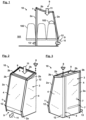
- Fig. 2 and 3 show schematic perspective views of the separation area from Fig.1 from the outside or the inside.
- the inflatable separation area 10 can be used, for example, in a passenger cabin of an aircraft 100, as is exemplified in Fig.7
- the separation area 10 serves as an isolation cabin or isolation cell for the containment of symptomatic cases, e.g. Person for the remainder of a flight to protect other passengers.
- separation area 10 can be used if a passenger is suspected of having a highly contagious disease or if this has already been confirmed.
- One aim of the separation area 10 described below is to provide a physical barrier for one or more potentially infectious persons, which can be set up quickly and easily even during the flight and does not entail any weight disadvantages.
- the separation area 10 is not limited to a fixed position in the vehicle interior 101, but can in principle be set up at different locations. The separation area 10 can be used multiple times and should be disinfected if necessary.
- Fig.1 shows the situation in a sectional view from behind with respect to a longitudinal extension of the aircraft 100.
- the separation area 10 comprises a support structure 1, which has a plurality of interconnected inflatable tubes 2a, 2b made of a flexible material, which are arranged and designed to form a self-supporting frame structure for the separation area 10 in an inflated state.
- a support structure 1 which has a plurality of interconnected inflatable tubes 2a, 2b made of a flexible material, which are arranged and designed to form a self-supporting frame structure for the separation area 10 in an inflated state.
- three essentially vertically running hoses 2a are provided, which stand on a floor of the aircraft 100 and form a kind of tripod. At an upper end they are held together by a ring or square made of four transversely running hoses 2b.
- the hoses 2a, 2b form a common volume which can be filled with air via a suitably mounted valve using a hand pump, a small compressor and/or a compressed air source installed on board the aircraft 100.
- the separating device 10 further comprises a pressure control device 13 which can be used to control and/or adjust an internal pressure of the hoses 2a, 2b.
- the pressure control device 13 can comprise, for example, a pressure sensor and a pressure display.
- the above-mentioned valve can be integrated into the pressure control device 13.
- the pressure causes the hoses 2a, 2b to stiffen and form a kind of self-supporting framework or skeleton, which defines the outer contour of the separation area 10 and gives it stability and stability.
- the internal pressure of the hoses 2a, 2b can be determined during the installation of the Separating device 10 can be adjusted once in such a way that the separating device 10 remains stable even in the event of pressure changes within the vehicle interior 101, e.g. even after the aircraft 100 has landed.
- the vertical hoses 2a are, for example, partially provided with kinks 12, while the transverse hoses 2b are slightly curved in order to follow an inner contour of the vehicle interior 101 as far as possible.
- the vertical hose 2a facing the aisle is straight, whereas the two opposite hoses 2a rest against an outer wall of the aircraft 101 and are bent to this end and run slightly diagonally along the outer wall.
- the transverse hoses 2b are adapted to the lower contour of a stowage or luggage compartment above (not shown).
- the support structure 10 therefore essentially fits snugly at the top and bottom with the inner contour of the vehicle interior 101, with the vertical hoses 2a standing on the floor and the transverse hoses 2b resting on the ceiling or the stowage compartment.
- the separation area 10 further comprises a casing 3, which comprises several flexible wall membranes 4, which connect the inflatable tubes 2a, 2b to one another in a planar manner and are designed to separate the separation area 10 from the vehicle interior 101 in the inflated state.
- the wall membranes 4 can be made from a transparent or semi-transparent flame-retardant thermoplastic film.
- the tubes 2a, 2b of the supporting structure 1 can be made from the same material and can be welded to the wall membranes 4, for example.
- a separate cell is formed, the supporting structure of which is formed by the tubes 2a, 2b and the outer walls by the wall membranes 4.
- the separation area 10 is kept open at the top and bottom, with an air passage 9 at the top allowing the entry of fresh air 11 from the ventilation system of the aircraft 100.
- a slot-shaped air passage 9 is also provided near the floor, through which fresh air 11 can flow out of the separation area 10 (in this area the casing 3 does not fit exactly with the floor).
- the air supply can be regulated in such a way that the flow conditions effectively create a slight negative pressure within the separation area 10, so that, for example, viruses or other pathogens do not escape from the separation area 10, even if it is not hermetically sealed from the vehicle interior 101.
- a passenger 103 located in the separation area 10 still has access to a passenger service unit (PSU), emergency oxygen masks, etc. due to the upwardly open arrangement.
- PSU passenger service unit
- a resealable passage opening 5 for entering and leaving the separation area 10 is incorporated in one of the wall membranes 4, which can be opened and closed using a zipper 6.
- an emergency exit from the separation area 10 could also be realized in this way, e.g. by using a safety zipper system such as the Quickburst system from the YKK Fastening Products Group or a corresponding system.
- a number of passages 7 for elements of the adjacent third seat 102 are also formed in the aisle-side wall membrane 4, e.g. for passing through an armrest and/or a seat frame.
- the wall membrane 4 can be slotted on one or more sides towards the passages 7 (not shown) so that the wall membrane 4 can be guided around the corresponding elements and, if necessary, fastened around them in this arrangement (e.g. using Velcro, snap fasteners, etc.).
- the separation area 10 of the Fig. 1 to 3 only supported by three essentially vertically running hoses 2a.
- the separating region 10 can further comprise one or more fastening elements 8.
- the transversely running hoses 2b are fixed to a ceiling, a storage compartment and/or a wall of the vehicle interior 101 via such fastening elements 8.
- a single fastening element 8 is shown, which is designed as a suction cup and is attached to the supporting structure 1 of the separation area 10 in an area under which, from a symmetry point of view, a fourth vertical support would have to be arranged.
- the fastening element 8 thus compensates for the missing vertically running hose 2a on the right in Fig.2 or front center in Fig.3 .
- Fixing using one or more suction cups offers the particular advantage that the separation area 10 can be retrofitted and installed in practically any cabin without the need for fastening means and/or special fastening points in the cabin.
- Fig. 4 to 6 a variant of the invention, which has four essentially vertically running hoses 2a.
- the aisle-side hoses 2a are also bent, for example to accommodate a different cabin shape or different geometric requirements.
- the result is an extremely lightweight (e.g. a few kilograms) yet particularly practical solution for an isolated area in a vehicle cabin, which can be folded up and stored in this form in a very space-saving manner (e.g. in a carrying bag). All that is required for installation is a device for filling with air (e.g. an air pump) and, if necessary, one or more fastening elements such as suction cups or hooks.
- air e.g. an air pump
- fastening elements e.g. an air pump
- the system also offers many advantages in terms of safety due to its low weight, flexibility, quick accessibility in the event of an emergency, etc.
- seats in the immediate vicinity of the separation area 10 can also be occupied without there being a relevant safety and/or infection risk for the passengers sitting there. This can generally improve seat occupancy.
Landscapes
- Engineering & Computer Science (AREA)
- Aviation & Aerospace Engineering (AREA)
- Transportation (AREA)
- Mechanical Engineering (AREA)
- Air Bags (AREA)
Description
Die vorliegende Erfindung betrifft einen aufblasbaren Trennbereich für einen Fahrzeuginnenraum, insbesondere für eine Passagierkabine eines Luftfahrzeugs.The present invention relates to an inflatable partition area for a vehicle interior, in particular for a passenger cabin of an aircraft.
Im Flugzeugdesign und Flugzeugbau gibt es kontinuierlich Bestrebungen, die Produktionseffizienz und -kosten, den Montageaufwand und die Montagezeit sowie die Nachhaltigkeit zu verbessern und das Gesamtgewicht bei gleichbleibender oder verbesserter Bauteilperformance zu reduzieren, wobei jederzeit ein besonderer Fokus auf Komfort und Sicherheit der Passagiere gelegt wird. In den letzten Jahren gab es in der Luftfahrtindustrie vereinzelte Versuche, aufblasbare Strukturen als gewichtssparende Lösungen für den Innen- und Außenbereich von Flugzeugen zu nutzen. Aufblasbare Komponenten sind in anderen Technologiebereichen bereits weit verbreitet, z. B. in der Freizeitindustrie und im Campingbereich, wo sie unter anderem aufblasbare Zelte, Sitz- und/oder Liegevorrichtungen, schwimmfähige Vorrichtungen und so weiter umfassen. Um solche Strukturen im Bereich der Luftfahrt einsetzen zu können, sind jedoch zusätzliche Herausforderungen zu bewältigten. Unter anderem ist relativ großen Druckunterschieden zu wiederstehen. Bevorzugte Materialien sind nachhaltig und langlebig und erfüllen sämtliche Sicherheitsanforderungen beispielsweise hinsichtlich der Entflammbarkeit. Außerdem wäre es wünschenswert, die Geometrie der aufblasbaren Vorrichtungen im aufgeblasenen Zustand möglichst stabil zu gestalten.In aircraft design and construction, there are continuous efforts to improve production efficiency and costs, assembly effort and time, sustainability, and to reduce overall weight while maintaining or improving component performance, with a special focus on passenger comfort and safety at all times. In recent years, there have been isolated attempts in the aviation industry to use inflatable structures as weight-saving solutions for the interior and exterior of aircraft. Inflatable components are already widely used in other technology areas, e.g. in the leisure industry and in the camping sector, where they include inflatable tents, seating and/or reclining devices, buoyant devices, and so on. However, in order to be able to use such structures in the aviation sector, additional challenges must be overcome. Among other things, relatively large pressure differences must be withstood. Preferred materials are sustainable and durable and meet all safety requirements, for example with regard to flammability. In addition, it would be desirable to make the geometry of the inflatable devices as stable as possible when inflated.
Als Beispiel für eine solche aufblasbare Vorrichtung beschreibt die Druckschrift
Als weiteres Beispiel beschreiben die Druckschriften
Weiterhin beschreibt die Druckschrift
Vor diesem Hintergrund liegt der vorliegenden Erfindung die Aufgabe zugrunde, verbesserte gewichtssparende Lösungen zur Abtrennung von begrenzten Kabinenbereichen von Luftfahrzeugen zu finden, die sich möglichst einfach und schnell auch noch während des Betriebs auf- und abbauen lassen.Against this background, the present invention is based on the object of providing improved weight-saving solutions for separating limited cabin areas of aircraft that can be assembled and dismantled as easily and quickly as possible, even during operation.
Erfindungsgemäß wird diese Aufgabe gelöst durch einen aufblasbaren Trennbereich mit den Merkmalen des Patentanspruchs 1 sowie durch ein Luftfahrzeug mit den Merkmalen des Patentanspruchs 14.According to the invention, this object is achieved by an inflatable separation area with the features of
Eine der vorliegenden Erfindung zugrunde liegende Idee besteht darin, einen schnell und einfach auf- und abzubauenden abgetrennten Bereich für einen Fahrzeuginnenraum zu schaffen, indem aufblasbare flexible Schläuche als Stützstrukturen kombiniert werden mit dünnen flexiblen Wandmembranen, welche einen Innenraum des Trennbereichs von dem Fahrzeuginnenraum absondern. Die Schläuche dienen dabei gewissermaßen als stützendes bzw. tragendes Gerüst/Skelett vergleichbar zu den Zeltstangen eines Zeltes und definieren gleichzeitig eine Außenkontur des abzutrennenden Bereichs. Die Wandmembranen sorgen für die eigentliche Abtrennung des derart geschaffenen Innenraums von dem Fahrzeuginnenraum, insbesondere in horizontaler Richtung.One idea underlying the present invention is to create a separated area for a vehicle interior that can be set up and dismantled quickly and easily by combining inflatable flexible tubes as support structures with thin flexible wall membranes that separate an interior of the separation area from the vehicle interior. The tubes serve as a supporting or load-bearing framework/skeleton, comparable to the tent poles of a tent, and at the same time define an outer contour of the area to be separated. The wall membranes provide the actual Separation of the interior space created in this way from the vehicle interior, in particular in the horizontal direction.
Zur Montage können die Schläuche mit einem oder mehreren Ventilen versehen sein, über welche das System mit einer Luftpumpe, einem Blasebalg, einer Gaskartusche und/oder einem Kompressor an geeigneter Position aufpumpbar sein kann. Prinzipiell können hierzu auch bereits an Bord des Fahrzeugs vorhandene Systeme genutzt werden, welche kurzfristig Druckluft bereitstellen können, z.B. ein Luftaufbereitungssystem und/oder ein Kompressor-System eines Flugzeugs. Sobald die Schläuche ausreichend aufgeblasen sind, spannen sie die dazwischenliegenden Wandmembranen auf, welche dann die Wände des Trennbereichs bilden. Spezielle weitere Werkzeuge oder Hilfsmittel werden für die Installation nicht zwingend benötigt. Die konkrete Aufstellposition kann hierbei je nach Innengestaltung des Fahrzeuginnenraums besonders flexibel auch kurzfristig wählbar sein.For assembly, the hoses can be fitted with one or more valves, through which the system can be inflated at a suitable position using an air pump, a bellows, a gas cartridge and/or a compressor. In principle, systems already on board the vehicle that can provide compressed air at short notice can also be used for this purpose, e.g. an air treatment system and/or an aircraft compressor system. As soon as the hoses are sufficiently inflated, they stretch the wall membranes between them, which then form the walls of the separation area. No other special tools or aids are necessarily required for installation. The specific installation position can be selected particularly flexibly, even at short notice, depending on the interior design of the vehicle.
Die derart geschaffene Trennkabine bzw. Trennzelle kann innerhalb des Fahrzeuginnenraums für unterschiedlichste Zwecke eingesetzt werden, wobei die einfache Konstruktion einen Auf- und/oder Abbau des Systems auch sehr kurzfristig während des Betriebs des Fahrzeugs gestattet. Solange der Trennbereich nicht benutzt wird, kann dieser in zusammengefalteter Form platzsparend verstaut werden. Hierbei macht man sich zunutze, dass der Aufbau des Systems in besonders gewichtssparender Weise realisiert werden kann, indem für das flexible Material der Schläuche und Wandmembranen geeignete dünne Materialien verwendet werden, die gleichzeitig entsprechende Sicherheitsanforderungen hinsichtlich Entflammbarkeit, Altersbeständigkeit, Reißfestigkeit, Umweltverträglichkeit usw. erfüllen können. Dabei kann das System je nach Bedarf auch mehrmals verwendet werden. Beispielweise kann der Trennbereich an Bord eines sich bereits in der Luft befindlichen Flugzeugs aufgebaut werden, um einen oder mehrere Passagiere von den übrigen Passagieren zu isolieren, z.B. im Falle eines medizinischen Notfalls, einer hochansteckenden Infektion oder dergleichen. Es versteht sich dabei jedoch, dass ein aufblasbarer Trennbereich im Sinne der Erfindung nicht nur als Schutzmaßnahme für medizinzische bzw. infektiologische Anwendungen eingesetzt werden kann. Weiterhin können mittels der Erfindung kurzfristig, aber auch dauerhaft, Ruhezonen in einer Passagierkabine geschaffen werden, sei es für Passagiere, sei es für das Bordpersonal. Je nach dem konkreten Anwendungsfall können die Wandmembranen der Hülle dabei durchsichtig oder mehr oder weniger undurchsichtig gestaltet sein.The separation cabin or cell created in this way can be used for a wide variety of purposes inside the vehicle, with the simple construction allowing the system to be set up and/or dismantled at very short notice while the vehicle is in operation. When the separation area is not in use, it can be folded up and stowed away to save space. This takes advantage of the fact that the system can be constructed in a particularly weight-saving manner by using suitable thin materials for the flexible material of the hoses and wall membranes, which can also meet the corresponding safety requirements in terms of flammability, age resistance, tear resistance, environmental compatibility, etc. The system can also be used several times as required. For example, the separation area can be set up on board an aircraft that is already in the air in order to isolate one or more passengers from the other passengers, e.g. in the event of a medical emergency, a highly contagious infection or the like. It is understood, however, that an inflatable separation area within the meaning of the invention can be used not only as a protective measure for medical or infectious disease applications. Furthermore, the invention can be used to create short-term or permanent rest areas in a passenger cabin, either for passengers or for the cabin crew. Depending on the specific application, the wall membranes of the shell can be transparent or more or less opaque.
Vorteilhafte Ausgestaltungen und Weiterbildungen ergeben sich aus den weiteren Unteransprüchen sowie aus der Beschreibung unter Bezugnahme auf die Figuren.Advantageous embodiments and further developments emerge from the further subclaims and from the description with reference to the figures.
Gemäß einer Weiterbildung kann der Trennbereich in dem aufgeblasenen Zustand nach oben und unten hin offen ausgebildet sein. Beispielsweise kann der Trennbereich lediglich auf allen horizontalen Seiten von den Wandmembranen umgeben sein und auf einem Boden des Fahrzeuginnenraums aufsitzen. Eine verbleibende Öffnung nach oben hin kann beispielsweise zur Luftzufuhr genutzt werden. Ebenso kann es vorgesehen sein, dass der Trennbereich nach oben und unten passgenau mit einem Boden und einer Decke des Fahrzeuginnenraums abschließt.According to a further development, the separation area can be designed to be open at the top and bottom when inflated. For example, the separation area can only be surrounded by the wall membranes on all horizontal sides and can rest on a floor of the vehicle interior. A remaining opening at the top can be used, for example, to supply air. It can also be provided that the separation area fits precisely at the top and bottom with a floor and a ceiling of the vehicle interior.
Im Prinzip ist es zudem denkbar, dass der Trennbereich nicht auf allen horizontalen Seiten geschlossen ist, sondern lediglich auf denjenigen Seiten Wandmembranen aufweist, welche in den Fahrzeuginnenraum hinein ausgerichtet sind und nicht bereits ohnehin durch Innenwände des Fahrzeuginnenraums begrenzt werden. Anders formuliert kann es in bestimmten Anwendungen vorgesehen sein, eine oder mehrere Innenwände der Fahrzeugkabine als Außenwände des Trennbereichs zu nutzen. In diesem Fall könnte beispielsweise eine Außenwand des Fahrzeugs nicht durch die Wandmembranen abgedeckt sein und diese könnten lediglich gangseitig und nach vorn und hinten vorgesehen sein.In principle, it is also conceivable that the separation area is not closed on all horizontal sides, but only has wall membranes on those sides that are aligned into the vehicle interior and are not already are limited by the interior walls of the vehicle interior anyway. In other words, in certain applications it may be intended to use one or more interior walls of the vehicle cabin as the exterior walls of the separation area. In this case, for example, an exterior wall of the vehicle could not be covered by the wall membranes and these could only be provided on the aisle side and to the front and rear.
Gemäß einer Weiterbildung können die Tragkonstruktion und die Hülle dazu ausgebildet sein, den Trennbereich nach oben und unten hin zumindest bereichsweise passgenau mit dem Fahrzeuginnenraum abzuschließen.According to a further development, the supporting structure and the shell can be designed to close the separating area at the top and bottom with the vehicle interior at least in some areas.
Der Trennbereich kann somit rundherum auf dem Boden des Fahrzeuginnenraums aufsitzen und an eine Decke anstoßen, ohne dass eine (zumindest randseitige) Öffnung zum Fahrzeuginnenraum hin verbleibt. Eine Luftzufuhr in den Trennbereich kann in diesem Fall beispielsweise über oben und unten (prinzipiell aber auch seitlich) angeordnete und in die Wandmembranen eingelassene Luftschlitze oder dergleichen erfolgen. Die Luft kann über Luftauslässe in einer über dem Trennbereich liegenden Decke des Fahrzeuginnenraums herbeigeführt und über entsprechende Luftablässe im Boden des Fahrzeuginnenraums wieder abgelassen werden. Alternativ kann es vorgesehen sein, dass der Trennbereich nach oben und/oder unten hin nicht vollständig mit dem Fahrzeuginnenraum abschließt, sondern Lüftungsschlitze verbleiben, über die der Trennbereich mit dem Fahrzeuginnenraum luftdurchlässig verbunden bleibt. Weiterhin können alternativ oder zusätzlich Lüftungselemente in die Tragkonstruktion und/oder die Hülle des Trennbereichs integriert sein.The partition area can thus sit all around on the floor of the vehicle interior and abut against a ceiling without leaving an opening (at least at the edge) to the vehicle interior. In this case, air can be supplied to the partition area, for example, via air slots or the like arranged at the top and bottom (but in principle also at the sides) and let into the wall membranes. The air can be introduced via air outlets in a ceiling of the vehicle interior above the partition area and let out again via corresponding air outlets in the floor of the vehicle interior. Alternatively, it can be provided that the partition area does not completely close off from the vehicle interior at the top and/or bottom, but that ventilation slots remain through which the partition area remains connected to the vehicle interior in an air-permeable manner. Furthermore, alternatively or additionally, ventilation elements can be integrated into the supporting structure and/or the shell of the partition area.
Gemäß einer Weiterbildung können mindestens drei der Schläuche als im Wesentlichen vertikalverlaufende Streben ausgebildet sein. Weitere Schläuche können als Querverbindungen der Streben dienen.According to a further development, at least three of the tubes can be designed as essentially vertical struts. Additional tubes can serve as cross connections for the struts.
Beispielsweise kann der Trennbereich einen rechteckigen Grundriss aufweisen, wobei vier im Wesentlichen vertikal verlaufende Schläuche Außenkanten des Trennbereichs bilden und diese an einem oberen Ende von vier querverlaufenden Schläuchen zusammengehalten werden. Es versteht sich jedoch, dass auch komplexere Außengeometrien und/oder Schlauchanordnungen möglich sind.For example, the separation area can have a rectangular floor plan, with four essentially vertically running hoses forming outer edges of the separation area and these being held together at an upper end by four transversely running hoses. However, it is understood that more complex external geometries and/or hose arrangements are also possible.
Gemäß einer Weiterbildung können drei vertikalverlaufende Schläuche als Außenkanten des Trennbereichs an einem oberen Ende an drei Ecken eines durch vier querverlaufende Schläuche gebildeten Vierecks angebunden sein.According to a further development, three vertically running hoses can be connected as outer edges of the separation area at an upper end to three corners of a square formed by four transversely running hoses.
In dieser Weiterbildung wird sich die Erkenntnis zunutze gemacht, dass prinzipiell drei Außenstreben eine ausreichende Stabilität bzw. Standfestigkeit für einen Trennbereich bieten können, sofern diese an einem oberen Ende von entsprechenden Querverbindungen zusammengehalten werden. Die hierdurch offen bzw. frei gehaltene vierte Kante der Struktur kann beispielsweise als Ausgangs- bzw. Eintrittsbereich genutzt werden, sodass mehr Bewegungsfreiraum verbleiben kann als im Falle, dass eine vierte vertikal verlaufende Strebe vorgesehen wäre. Dies kann beispielsweise im Falle von Notfällen besonders vorteilhaft sein, damit der Trennbereich möglichst einfach und unkompliziert verlassen werden kann.This development makes use of the knowledge that, in principle, three external struts can provide sufficient stability or sturdiness for a separation area, provided they are held together at an upper end by appropriate cross connections. The fourth edge of the structure, which is kept open or free in this way, can be used, for example, as an exit or entry area, so that more freedom of movement can remain than if a fourth vertical strut were provided. This can be particularly advantageous in the event of an emergency, for example, so that the separation area can be left as easily and simply as possible.
Die Standfestigkeit dieser an ein Dreibein erinnernden Anordnung kann weiter verbessert werden, indem beispielsweise ein Befestigungselement an einem oberen Ende vorgesehen wird, insbesondere im Bereich der "offenen Kante", an welcher kein vertikalverlaufender Schlauch vorhanden ist, und dort beispielsweise an einer Wand und/oder Deck des Fahrzeuginnenraums fixiert wird.The stability of this tripod-like arrangement can be further improved by, for example, providing a fastening element at an upper end, particularly in the area of the "open edge" where there is no vertical hose and it is fixed there, for example, to a wall and/or deck of the vehicle interior.
Gemäß einer Weiterbildung kann zumindest ein Anteil der Schläuche zur Anpassung an eine Innenkontur des Fahrzeuginnenraums geknickt und/oder gekrümmt ausgebildet sein.According to a further development, at least a portion of the hoses can be kinked and/or curved to adapt to an inner contour of the vehicle interior.
Die durch die Schläuche definierte Außenkontur des Trennbereichs kann sich somit mehr oder weniger genau an eine Innenkontur des Fahrzeuginnenraums anschmiegen. Damit kann einerseits der vorhandene Raum optimal ausgenutzt werden. Andererseits kann der Trennbereich somit in besonders vorteilhafter Weise von Innenwänden oder anderen Strukturen des Fahrzeuginnenraums gestützt und stabilisiert werden, sodass der Trennbereich auch bei ruckartigen Bewegungen des Fahrzeugs möglichst in einer gewünschten Position verharrt.The outer contour of the separation area defined by the hoses can thus conform more or less precisely to the inner contour of the vehicle interior. On the one hand, this allows the available space to be used optimally. On the other hand, the separation area can be supported and stabilized in a particularly advantageous manner by inner walls or other structures of the vehicle interior, so that the separation area remains in the desired position as far as possible even when the vehicle moves suddenly.
Gemäß einer Weiterbildung können die Schläuche ein gemeinsam aufblasbares Volumen bilden.According to a further development, the tubes can form a jointly inflatable volume.
Damit kann die Tragkonstruktion des Trennbereichs ggf. über ein einzelnes Ventil unter Druck gesetzt werden, z.B. vergleichbar zu einer Luftmatratze, bei welcher mehrere miteinander verbundene Luftkammern über ein einzelnes Ventil mit Luft befüllt werden können.This means that the supporting structure of the separation area can be pressurized via a single valve if necessary, e.g. comparable to an air mattress, in which several interconnected air chambers can be filled with air via a single valve.
Gemäß einer Weiterbildung können die Wandmembranen zumindest bereichsweise transparent und/oder transluzent ausgebildet sein.According to a further development, the wall membranes can be transparent and/or translucent at least in some areas.
Beispielsweise kann eine durchsichtige Wandmembran in einer medizinischen Anwendung ermöglichen, dass ein Patient bzw. Passagier von außerhalb des Trennbereichs ärztlich beobachtet werden kann. Andererseits kann es im Falle einer Nutzung des Trennbereichs als Ruhebereich oder Schlafkoje gerade unerwünscht sein, dass der Trennbereich einsehbar ist. In diesem Fall würde man sich somit für undurchsichtige Wandmembranen entscheiden.For example, a transparent wall membrane in a medical application can allow a patient or passenger to enter the separation area from outside can be observed by a doctor. On the other hand, if the separation area is used as a rest area or sleeping area, it may be undesirable for the separation area to be visible. In this case, opaque wall membranes would be chosen.
Als weiterer Vorteil ergibt sich hierbei, dass der Trennbereich bei ausreichend transparenter Ausführung bei der Landung geschlossen stehen bleiben kann. Dementgegen müssen die typischerweise in Flugzeugen verwendeten undurchsichtigen Vorhänge stets geöffnet werden. Das vorliegende System kann hingegen aufgrund der Verwendung von transparentem Material einsehbar gestaltet sein. Die luftgefüllten Elemente stellen dabei keine Verletzungsgefahr da. Hinzu tritt eine leichte Bauweise und ggf. schnelle Öffnungsmöglichkeiten, beispielsweise durch einen leicht zu öffnenden Reißverschluss.Another advantage is that the partition area can remain closed during landing if it is sufficiently transparent. In contrast, the opaque curtains typically used in aircraft must always be opened. The present system, however, can be designed to be visible due to the use of transparent material. The air-filled elements do not pose a risk of injury. In addition, there is a lightweight construction and, if necessary, quick opening options, for example with an easy-to-open zipper.
Gemäß einer Weiterbildung können die Wandmembranen jeweils eine flammenhemmende thermoplastische Kunststofffolie aufweisen.According to a further development, the wall membranes can each have a flame-retardant thermoplastic film.
Beispielsweise können extrudierte Folien aus unterschiedlichen Polymerzusammensetzungen mit der Eignung für eine thermoplastische Verarbeitung verwendet werden, die entsprechende mechanische (z.B. Festigkeit, Abriebbeständigkeit, Flexibilität), chemische (z.B. feuerdämmend bzw. feuerfest, chemikalienbeständig) und/oder biologische Eigenschaften bereitstellen (z.B. Umweltverträglichkeit, Eignung für medizinische Anwendungen). In einem konkreten Beispiel kann eine Polyurethanfolie aus Polyester oder Polyether derartige Eigenschaften erfüllen.For example, extruded films made of different polymer compositions suitable for thermoplastic processing can be used, providing corresponding mechanical (e.g. strength, abrasion resistance, flexibility), chemical (e.g. fire retardant or fireproof, chemical resistant) and/or biological properties (e.g. environmental compatibility, suitability for medical applications). In a concrete example, a polyurethane film made of polyester or polyether can fulfill such properties.
Gemäß einer Weiterbildung können die Wandmembranen und die Schläuche aus dem gleichen flexiblen Material gefertigt sein.According to a further development, the wall membranes and the hoses can be made of the same flexible material.
Der Trennbereich kann somit insbesondere vollständig aus einem bestimmten geeigneten Material gewissermaßen "en bloc" gefertigt sein, wobei eine einheitliche Optik geschaffen wird, bei welcher die Tragkonstruktion und die Hülle die gleichen vorteilhaften Eigenschaften aufweisen. Ferner können die Wandmembranen mit den Schläuchen verschweißt, verklebt und/oder vernäht sein. Beispielsweise können in einer medizinischen Anwendung sowohl die Schläuche als auch die Wandmembranen aus dem gleichen transparenten oder semi-transparentem Material bestehen.The separation area can thus be made entirely from a certain suitable material, so to speak "en bloc", creating a uniform appearance in which the supporting structure and the casing have the same advantageous properties. Furthermore, the wall membranes can be welded, glued and/or sewn to the tubes. For example, in a medical application, both the tubes and the wall membranes can be made of the same transparent or semi-transparent material.
Gemäß einer Weiterbildung kann zumindest eine der Wandmembranen mit einer wiederverschließbaren Durchgangsöffnung zum Betreten und Verlassen des Trennbereichs durch Personen ausgebildet sein.According to a further development, at least one of the wall membranes can be designed with a resealable passage opening for persons to enter and leave the separation area.
Der Durchgang kann beispielsweise von medizinischem Personal genutzt werden, um einen Patienten zu inspizieren. Ebenso kann ein derartiger Durchgang als Notausgang vorgesehen sein.The passage can be used, for example, by medical personnel to inspect a patient. Such a passage can also be intended as an emergency exit.
Gemäß einer Weiterbildung kann die Durchgangsöffnung über einen Reißverschluss wiederverschließbar sein.According to a further development, the passage opening can be reclosable with a zipper.
Reißverschlüsse, insbesondere bestimmte Sicherheitsreißverschlüsse, können als ggf. wiederverwendbare Sicherheitsöffnungssysteme eine schnelle und kontrollierte Öffnung von Notausgangsöffnungen gewährleisten. Zum Schutz gegen Hitze und Flammen können beispielsweise Reißverschluss-Elemente aus flammhemmendem Polyamid mit einem Band aus Aramidfasern kombiniert werden.Zippers, especially certain safety zippers, can be used as reusable safety opening systems to ensure quick and controlled opening of emergency exits. For example, to protect against heat and flames, zipper elements made of flame-retardant polyamide can be combined with a band made of aramid fibers.
Es versteht sich dabei jedoch, dass je nach Anwendung grundsätzlich auch andere Verschließsystem zum Einsatz kommen können, z.B. Klettverschluss, Druckknöpfe, Magnete etc.However, it is understood that, depending on the application, other fastening systems can also be used, e.g. Velcro, snap fasteners, magnets, etc.
Gemäß einer Weiterbildung dann die Trenneinrichtung weiterhin eine Druckkontrolleinrichtung aufweisen, welche dazu ausgebildet ist, einen Innendruck der Schläuche zu kontrollieren.According to a further development, the separating device may further comprise a pressure control device which is designed to control an internal pressure of the hoses.
Beispielsweise kann die Druckkontrolleinrichtung eine mit einem Drucksensor gekoppelte Anzeige umfassen, welche eine aktuellen Innendruck der Schläuche anzeigt, sodass jederzeit überprüft werden kann, ob der Innendruck in einem geeigneten Druckintervall liegt bzw. einen geeigneten Wert aufweist. Ferner kann die Druckkontrolleinrichtung ein Ventil aufweisen, über welches der Innendruck der Schläuche eingestellt werden kann bzw. welches einen bestimmten gewünschten Innendruck vorgibt.For example, the pressure control device can comprise a display coupled to a pressure sensor, which shows the current internal pressure of the hoses, so that it can be checked at any time whether the internal pressure is within a suitable pressure interval or has a suitable value. Furthermore, the pressure control device can comprise a valve, via which the internal pressure of the hoses can be adjusted or which specifies a certain desired internal pressure.
Dementsprechend kann die Druckkontrolleinrichtung unter anderem dazu genutzt werden, den Druck einmalig beim Aufstellen der Trenneinrichtung geeignet einzustellen. Prinzipiell kann dann im weiteren Betrieb nachkorrigiert werden, sofern eine relevante Druckänderung, z.B. ein Druckabfall, in den Schläuchen angezeigt wird.Accordingly, the pressure control device can be used, among other things, to set the pressure appropriately once when setting up the separating device. In principle, corrections can then be made during further operation if a relevant pressure change, e.g. a pressure drop, is indicated in the hoses.
Wird die Trenneinrichtung der Erfindung beispielsweise in der Luft während des Flugs eines Luftfahrzeugs aufgebaut, so kann von dem Bordpersonal sichergestellt werden, dass der Innendruck der Schläuche ausreichend bemessen ist, um eine Standfestigkeit der Trenneinrichtung auch gegenüber den im weiteren Verlauf des Betriebs zu erwartenden Druckänderungen im Fahrzeuginnenraum zu gewährleisten. So kann es beispielsweise gefordert sein, dass die Trenneinrichtung bis zur Landung stehen bleibt. Der Innendruck der Schläuche kann hierzu direkt beim Installieren bzw. Aufbauen der Trenneinrichtung derart vom Personal (einmalig) gezielt mit einem Überdruck eingestellt werden, dass die Trenneinrichtung auch noch nach der Landung und dem damit verbundenen Druckanstieg in der Kabine stabil stehen bleibt. Falls notwendig kann mit Hilfe der Druckkontrolleinrichtung der aktuelle Druck jedoch im Betrieb jederzeit kontrolliert und ggf. nachgeregelt werden.If the separating device of the invention is set up in the air during the flight of an aircraft, for example, the on-board personnel can ensure that the internal pressure of the hoses is sufficiently dimensioned to ensure the stability of the separating device even against the pressure changes to be expected in the vehicle interior during further operation. For example, it may be required that the separating device is Landing. The internal pressure of the hoses can be set by the staff (once) to an overpressure directly when installing or setting up the separator so that the separator remains stable even after landing and the associated increase in pressure in the cabin. If necessary, the current pressure can be checked at any time during operation using the pressure control device and adjusted if necessary.
Prinzipiell kann die Druckkontrolleinrichtung darüber hinaus auch zur (ggf. automatischen) Regelung des Innendrucks der Schläuche ausgebildet sein. Allerdings kann in einfachen Ausgestaltungen der Erfindungen eine Nachregelung des Drucks auch beispielsweise händisch durch das Bordpersonal erfolgen und die Druckkontrolleinrichtung lediglich der Anzeige des aktuellen Innendrucks dienen.In principle, the pressure control device can also be designed to regulate the internal pressure of the hoses (if necessary automatically). However, in simple embodiments of the inventions, the pressure can also be adjusted manually by the on-board personnel, for example, and the pressure control device can only be used to display the current internal pressure.
Gemäß einer Weiterbildung können die Tragkonstruktion und die Hülle dazu ausgebildet sein, in dem aufgeblasenen Zustand zumindest einen Sitz des Fahrzeuginnenraums zu umgeben.According to a further development, the supporting structure and the cover can be designed to surround at least one seat of the vehicle interior in the inflated state.
In diesem Fall kann somit ein Sitz einer Sitzreihe in einem Fahrzeug samt dem dort sitzenden Passagier gegenüber dem Fahrzeuginnenraum isoliert werden. Beispielsweise kann ein Fensterplatz in einer Zweier- oder Dreierreihe in einem Flugzeug abgetrennt werden. Ebenso können mehrere oder alle Sitze einer Sitzreihe gegenüber dem Fahrzeuginnenraum und den davor bzw. dahinter liegenden Sitzreihen getrennt werden.In this case, a seat in a row of seats in a vehicle, together with the passenger sitting there, can be isolated from the vehicle interior. For example, a window seat in a row of two or three in an airplane can be separated. Likewise, several or all seats in a row can be separated from the vehicle interior and the rows of seats in front of or behind it.
Gemäß einer Weiterbildung kann zumindest eine der Wandmembranen mit Durchführungen für Elemente von angrenzenden Sitzstrukturen des Fahrzeuginnenraums ausgebildet sein.According to a further development, at least one of the wall membranes can be designed with passages for elements of adjacent seat structures of the vehicle interior.
Häufig sind die einzelnen Sitze in einer Sitzreihe eines Flugzeugs fest miteinander verbunden, z.B. an Sitzgestell, Armlehne und/oder Sitzfläche. Damit der Trennbereich auch noch nachträglich um einen oder mehrere Passagiersitze herum installiert werden kann, können somit eine oder mehrere Durchführungen in den Wandmembranen vorgesehen sein. Beispielsweise können die Wandmembranen zudem geeignet geschlitzt sein, sodass jede Wandmembran um die entsprechende Struktur des Sitzes gelegt werden kann. Geeignete Verschlusssysteme wie Klett, Druckknöpfe oder Reißverschlüsse können dann genutzt werden, um verbleibende Lücken oder Ritzen zwischen der oder den Wandmembranen und der Sitzstruktur zu verschließen.The individual seats in a row of seats on an aircraft are often firmly connected to one another, e.g. to the seat frame, armrest and/or seat surface. So that the separation area can also be subsequently installed around one or more passenger seats, one or more openings can be provided in the wall membranes. For example, the wall membranes can also be suitably slotted so that each wall membrane can be placed around the corresponding structure of the seat. Suitable fastening systems such as Velcro, snap fasteners or zippers can then be used to close any remaining gaps or cracks between the wall membrane(s) and the seat structure.
Gemäß einer Weiterbildung kann der Trennbereich weiterhin zumindest ein Befestigungselement zur Positionsfixierung des Trennbereichs in dem Fahrzeuginnenraum aufweisen.According to a further development, the separating region can further comprise at least one fastening element for fixing the position of the separating region in the vehicle interior.
Insbesondere kann das Befestigungselement ein Saugnapf und/oder ein Haken oder ein ähnliches geeignetes Hilfsmittel sein.In particular, the fastening element can be a suction cup and/or a hook or a similar suitable aid.
Auch wenn die Tragkonstruktion den Trennbereich grundsätzlich ausreichend stabilisieren bzw. stützen kann, kann es zusätzlich von Vorteil sein, wenn der Trennbereich darüber hinaus über ein oder mehrere Elemente beispielsweise an einer Wand und/oder einer Decke des Fahrzeuginnenraums fixiert werden kann. Dies kann beispielsweise aus sicherheitstechnischer Hinsicht Vorteile bieten, z.B. bei unvorhergesehenen ruckartigen Bewegungen des Fahrzeugs, damit die Positionierung und Orientierung des Trennbereichs jederzeit eingehalten wird.Even if the supporting structure can generally stabilize or support the separation area sufficiently, it can also be advantageous if the separation area can also be fixed using one or more elements, for example to a wall and/or ceiling of the vehicle interior. This can offer advantages from a safety point of view, for example in the event of unexpected, jerky movements of the vehicle, so that the positioning and orientation of the separation area is maintained at all times.
Hierbei stellen Saugnäpfe eine beispielhafte und vorteilhafte Möglichkeit dar, welche eine Fixierung an praktisch beliebigen Flächen erlaubt, die wieder entfernt werden kann, ohne Spuren zu hinterlassen. Es versteht sich, dass alternativ oder zusätzlich auch andere Befestigungselemente zum Einsatz kommen können, z.B. Haken, Bänder, Schlaufen, Klebehalter usw. Beispielsweise könnte das System über einen Haken-Handlauf an einem Gepäckfach befestigt werden.Suction cups are an exemplary and advantageous option, which allows fixation to practically any surface, which can be removed again can be removed without leaving any traces. It goes without saying that alternatively or in addition, other fastening elements can be used, e.g. hooks, straps, loops, adhesive holders, etc. For example, the system could be attached to a luggage compartment using a hook handrail.
Die vorliegende Erfindung wird nachfolgend anhand der in den schematischen Figuren angegebenen Ausführungsbeispiele näher erläutert. Es zeigen dabei:
- Fig. 1
- schematische Schnittansicht eines aufblasbaren Trennbereichs gemäß einer Ausführungsform der Erfindung;
- Fig. 2
- schematische Perspektivansicht des Trennbereichs aus
Fig. 1 von schräg außen; - Fig. 3
- schematische Perspektivansicht des Trennbereichs aus
Fig. 1 von schräg innen; - Fig. 4
- schematische Schnittansicht eines aufblasbaren Trennbereichs gemäß einer weiteren Ausführungsform der Erfindung;
- Fig. 5
- schematische Perspektivansicht des Trennbereichs aus
Fig. 4 von schräg außen; - Fig. 6
- schematische Perspektivansicht des Trennbereichs aus
Fig. 4 von schräg innen; und - Fig. 7
- schematische Draufsicht auf eine Passagierkabine eines Luftfahrzeugs mit einem Trennbereich gemäß der
Fig. 1 oder 4 .
- Fig.1
- schematic sectional view of an inflatable separation area according to an embodiment of the invention;
- Fig.2
- schematic perspective view of the separation area from
Fig.1 from the outside; - Fig.3
- schematic perspective view of the separation area from
Fig.1 from the inside; - Fig.4
- schematic sectional view of an inflatable separation area according to another embodiment of the invention;
- Fig.5
- schematic perspective view of the separation area from
Fig.4 from the outside; - Fig.6
- schematic perspective view of the separation area from
Fig.4 from the inside; and - Fig.7
- schematic plan view of a passenger cabin of an aircraft with a separation area according to the
Fig.1 or4 .
Die beiliegenden Figuren sollen ein weiteres Verständnis der Ausführungsformen der Erfindung vermitteln. Sie veranschaulichen Ausführungsformen und dienen im Zusammenhang mit der Beschreibung der Erklärung von Prinzipien und Konzepten der Erfindung. Andere Ausführungsformen und viele der genannten Vorteile ergeben sich im Hinblick auf die Zeichnungen. Die Elemente der Zeichnungen sind nicht notwendigerweise maßstabsgetreu zueinander gezeigt.The accompanying figures are intended to provide a further understanding of embodiments of the invention. They illustrate embodiments and, in conjunction with the description, serve to explain principles and concepts of the invention. Other embodiments and many of the noted advantages will be apparent upon reference to the drawings. The elements of the drawings are not necessarily shown to scale with respect to one another.
In den Figuren der Zeichnung sind gleiche, funktionsgleiche und gleich wirkende Elemente, Merkmale und Komponenten - sofern nichts anderes ausgeführt ist - jeweils mit denselben Bezugszeichen versehen.In the figures of the drawing, identical, functionally identical and acting elements, features and components are provided with the same reference symbols, unless otherwise stated.
Um das Risiko für die Verbreitung von Krankheitserregern durch Personen, die Symptome einer ansteckenden Erkrankung zeigen, zu minimieren, kommen in der Praxis verschiedenen Ansätze zum Einsatz. Einige gängige Ansätze zur Verhinderung der Ausbreitung von Krankheitserregern umfassen die Sicherstellung räumlicher Abstände zwischen Personen, die Reduzierung von Kontaktmöglichkeiten sowie die Durchsetzung persönlicher Schutzausrüstung wie beispielsweise Atemschutzmasken. So empfiehlt beispielsweise die IATA, wie auch andere Organisationen beim Verdacht auf eine ansteckende Erkrankung während eines Fluges einen Abstand von zwei Metern zwischen kranken Passagieren und anderen Passagieren einzuhalten. Diesen Empfehlungen ist gemein, dass ein erheblicher Anteil an Sitzplätzen nicht mehr genutzt werden kann.In practice, various approaches are used to minimize the risk of pathogens spreading through people who show symptoms of an infectious disease. Some common approaches to preventing the spread of pathogens include ensuring physical distance between people, reducing contact opportunities, and enforcing personal protective equipment such as respiratory masks. For example, the IATA, like other organizations, recommends that if an infectious disease is suspected during a flight, a distance of two meters should be maintained between sick passengers and other passengers. What these recommendations have in common is that a significant proportion of seats can no longer be used.
Ein Ziel des im Folgenden beschriebenen Trennbereichs 10 ist es, eine physikalische Barriere für einen oder mehrere möglicherweise infektiöse Personen bereitzustellen, welche auch noch während des Flugs schnell und einfach aufgebaut werden kann und keine Gewichtsnachteile mit sich bringt. Dabei ist der Trennbereich 10 insbesondere nicht auf eine fest vorgebebene Position in dem Fahrzeuginnenraum 101 beschränkt, sondern kann grundsätzlich an unterschiedlichen Standorten aufgestellt werden. Der Trennbereich 10 kann mehrfach verwendet werden und sollte hierzu ggf. desinfiziert werden.One aim of the
In dem Ausführungsbeispiel der
Der Trennbereich 10 umfasst eine Tragkonstruktion 1, welche mehrere miteinander verbundene aufblasbare Schläuche 2a, 2b aus einem flexiblen Material aufweist, die dazu angeordnet und ausgebildet sind, in einem aufgeblasenen Zustand eine selbststützende Rahmenstruktur für den Trennbereich 10 zu bilden. Wie
Die Schläuche 2a, 2b bilden dabei ein gemeinsames Volumen, welches über ein geeignet angebrachtes Ventil mittels einer Handpumpe, eines kleinen Kompressors und/oder einer an Bord des Luftfahrzeugs 100 installierten Druckluftquelle mit Luft gefüllt werden kann. Die Trenneinrichtung 10 umfasst weiterhin einen Druckkontrolleinrichtung 13, welche zur Kontrolle und/oder Einstellung eines Innendrucks der Schläuche 2a, 2b genutzt werden kann. Zu diesem Zweck kann die Druckkontrolleinrichtung 13 beispielsweise einen Drucksensor und eine Druckanzeige umfassen. Ferner kann das oben erwähnte Ventil in die Druckkontrolleinrichtung 13 integriert sein.The
Durch die Druckbeaufschlagung versteifen sich die Schläuche 2a, 2b und bilden dadurch eine Art selbsttragendes Gerüst oder Skelett, welches eine Außenkontur des Trennbereichs 10 vorgibt und diesem Stabilität und Standfestigkeit verleiht. Der Innendruck der Schläuche 2a, 2b kann dabei bereits bei der Aufstellung der Trenneinrichtung 10 einmalig derart eingestellt werden, dass die Trenneinrichtung 10 auch bei Druckänderungen innerhalb des Fahrzeugsinnenraums 101 weiterhin stabil stehen bleibt, z.B. auch noch nach der Landung des Luftfahrzeugs 100.The pressure causes the
Die vertikalen Schläuche 2a sind dabei beispielhaften teilweise mit Knicken 12 versehen, während die querverlaufenden Schläuche 2b leicht gekrümmt ausgebildet sind, um einer Innenkontur des Fahrzeuginnenraums 101 möglichst zu folgen. In dem konkreten Ausführungsbeispiel der
Der Trennbereich 10 umfasst weiterhin eine Hülle 3, welche mehrere flexible Wandmembranen 4 umfasst, die die aufblasbaren Schläuche 2a, 2b flächig miteinander verbinden und dazu ausgebildet sind, den Trennbereich 10 in dem aufgeblasenen Zustand gegenüber dem Fahrzeuginnenraum 101 abzutrennen. Beispielsweise können die Wandmembranen 4 hierbei aus einer transparenten oder semi-transparenten flammenhemmenden thermoplastischen Kunststofffolie gefertigt sein. Die Schläuche 2a, 2b der Tragkonstruktion 1 können aus dem gleichen Material gefertigt und mit den Wandmembranen 4 beispielsweise verschweißt sein.The
In der Summe wird somit eine abgetrennte Zelle gebildet, deren tragende Struktur durch die Schläuche 2a, 2b und deren Außenwände durch die Wandmembranen 4 gebildet werden. Nach oben und unten hin ist der Trennbereich 10 offen gehalten, wobei eine oben liegender Luftdurchlass 9 den Eintritt von Frischluft 11 aus dem Belüftungssystem des Flugzeugs 100 ermöglicht. An der Fensterseite des Fahrzeuginnenraums 101 (rechts in
Die Luftzufuhr kann dabei derart geregelt sein, dass sich durch die Strömungsverhältnisse effektiv ein geringer Unterdruck innerhalb des Trennbereichs 10 eingestellt wird, sodass beispielsweise Viren oder andere Krankheitserreger nicht aus dem Trennbereich 10 austreten, selbst wenn dieser nicht luftdicht gegenüber dem Fahrzeuginnenraum 101 abgeschlossen ist.The air supply can be regulated in such a way that the flow conditions effectively create a slight negative pressure within the
Ein sich in dem Trennbereich 10 befindender Passagier 103 hat aufgrund der nach oben hin geöffneten Anordnung weiterhin Zugriff auf eine Passagier-Serviceeinheit (PSU), Notfall-Sauerstoffmasken etc.A
In der Ausführungsform der
Damit die Hülle 3 die beiden Sitze 102 vollständig umgeben kann, sind ferner mehrere Durchführungen 7 für Elemente des angrenzenden dritten Sitzes 102 in der gangseitigen Wandmembran 4 ausgebildet, z.B. zur Durchführung einer Armlehne und/oder eines Sitzgestells. Die Wandmembran 4 kann hierzu von einer oder mehreren Seiten hin zu den Durchführungen 7 geschlitzt ausgebildet sein (nicht dargestellt), damit die Wandmembran 4 um die entsprechenden Elemente geführt und ggf. in dieser Anordnung um diese herum befestigt werden kann (z.B. über Klettverschluss, Druckknöpfe etc.).In order that the
Wie bereits erwähnt wurde, wird der Trennbereich 10 der
In
Als Alternative zu der Ausführungsform aus
Dem Fachmann wird hierbei klar sein, dass durch entsprechende Knickung und Biegungen der Schläuche 2a, 2b völlig unterschiedlichen geometrischen Bedingungen entsprochen werden kann. Ebenso ist die gezeigte Anzahl und Orientierung der Schläuche 2a, 2b rein beispielhaft zu verstehen.It will be clear to the person skilled in the art that completely different geometric conditions can be met by appropriate kinking and bending of the
Im Ergebnis wird eine extrem leichtgewichtige (z.B. wenige Kilogramm) und dennoch besonders praktische Lösung für einen isolierten Bereich in einer Fahrzeugkabine geschaffen, welche zusammenfaltbar und in dieser Form auch stark platzsparend verstaut werden kann (z.B. in einer Tragetasche). Für die Installation werden lediglich eine Gerät zum Befüllen mit Luft (z.B. eine Luftpumpe) und ggf. ein oder mehrere Befestigungselemente wie z.B. Saugnäpfe oder Haken benötigt. Auch in sicherheitskritischer Hinsicht bietet das System aufgrund des geringen Gewichts, der Flexibilität, der schnellen Zugänglichkeit im Falle eines Notfalls usw. viele Vorteile. Zudem können anders als in herkömmlichen Ansätzen auch Sitzplätze in unmittelbarer Umgebung des Trennbereichs 10 belegt werden, ohne dass ein relevantes Sicherheits- und/oder Infektionsrisiko für die dort sitzenden Passagiere vorhanden wäre. Damit kann die Sitzplatzbelegung im Allgemeinen verbessert werden.The result is an extremely lightweight (e.g. a few kilograms) yet particularly practical solution for an isolated area in a vehicle cabin, which can be folded up and stored in this form in a very space-saving manner (e.g. in a carrying bag). All that is required for installation is a device for filling with air (e.g. an air pump) and, if necessary, one or more fastening elements such as suction cups or hooks. The system also offers many advantages in terms of safety due to its low weight, flexibility, quick accessibility in the event of an emergency, etc. In addition, unlike conventional approaches, seats in the immediate vicinity of the
In der vorangegangenen detaillierten Beschreibung sind verschiedene Merkmale zur Verbesserung der Stringenz der Darstellung in einem oder mehreren Beispielen zusammengefasst worden. Es sollte dabei jedoch klar sein, dass die obige Beschreibung lediglich illustrativer, keinesfalls jedoch beschränkender Natur ist. Sie dient der Abdeckung aller Alternativen, Modifikationen und Äquivalente der verschiedenen Merkmale und Ausführungsbeispiele. Viele andere Beispiele werden dem Fachmann aufgrund seiner fachlichen Kenntnisse in Anbetracht der obigen Beschreibung sofort und unmittelbar klar sein.In the previous detailed description, various features to improve the stringency of the presentation are included in one or more examples It should be understood, however, that the above description is merely illustrative and not restrictive in nature. It is intended to cover all alternatives, modifications, and equivalents of the various features and embodiments. Many other examples will be readily and immediately apparent to those skilled in the art based on their technical knowledge in view of the above description.
Die Ausführungsbeispiele wurden ausgewählt und beschrieben, um die der Erfindung zugrundeliegenden Prinzipien und ihre Anwendungsmöglichkeiten in der Praxis bestmöglich darstellen zu können. Dadurch können Fachleute die Erfindung und ihre verschiedenen Ausführungsbeispiele in Bezug auf den beabsichtigten Einsatzzweck optimal modifizieren und nutzen. In den Ansprüchen sowie der Beschreibung werden die Begriffe "beinhaltend" und "aufweisend" als neutralsprachliche Begrifflichkeiten für die entsprechenden Begriffe "umfassend" verwendet. Weiterhin soll eine Verwendung der Begriffe "ein", "einer" und "eine" eine Mehrzahl derartig beschriebener Merkmale und Komponenten nicht grundsätzlich ausschließen.The embodiments were selected and described in order to best illustrate the principles underlying the invention and its possible applications in practice. This enables those skilled in the art to optimally modify and use the invention and its various embodiments in relation to the intended purpose. In the claims and the description, the terms "including" and "having" are used as neutral language terms for the corresponding terms "comprising". Furthermore, the use of the terms "a", "an" and "an" is not intended to fundamentally exclude a plurality of features and components described in this way.
- 11
- TragkonstruktionSupporting structure
- 2a, 2b2a, 2b
- SchlauchHose
- 33
- HülleCovering
- 44
- WandmembranWall membrane
- 55
- DurchgangsöffnungPassage opening
- 66
- Reißverschlusszipper
- 77
- Durchführungexecution
- 88th
- BefestigungselementFastener
- 99
- LuftdurchlassAir passage
- 1010
- aufblasbarer Trennbereichinflatable separation area
- 1111
- LuftzirkulationAir circulation
- 1212
- Knickkink
- 1313
- DruckkontrolleinrichtungPressure control device
- 100100
- LuftfahrzeugAircraft
- 101101
- FahrzeuginnenraumVehicle interior
- 102102
- SitzSeat
- 103103
- Passagierpassenger
Claims (14)
- Inflatable separating region (10) for a vehicle interior (101), in particular for a passenger cabin of an aircraft (100), having:a supporting structure (1) which has a plurality of interconnected inflatable tubes (2a, 2b) made of a flexible material and being arranged and designed so as, in an inflated state, to form a self-supporting frame structure for the separating region (10); anda covering (3) which comprises a plurality of flexible wall membranes (4) which connect the inflatable tubes (2a, 2b) to one another in a planar manner and are designed to separate off the separating region (10) in the inflated state from the vehicle interior (101), wherein the separating region (10) in the inflated state is open upwards, wherein the supporting structure (1) and the covering (3) are designed to close off the separating region (10) upwards at least in regions in a precisely fitting manner with the vehicle interior (101).
- Inflatable separating region (10) according to Claim 1, wherein at least three of the tubes (2a) are designed as substantially vertically running struts, with further tubes (2b) serving as transverse connections of the struts.
- Inflatable separating region (10) according to Claim 2, wherein three substantially vertically running tubes (2a) as outer edges of the separating region (10) are connected at an upper end at three corners of a rectangle formed by four transversely running tubes (2b).
- Inflatable separating region (10) according to one of Claims 1 to 3, wherein at least a portion of the tubes (2a, 2b) is kinked and/or curved for adaptation to an inner contour of the vehicle interior (101).
- Inflatable separating region (10) according to one of Claims 1 to 4, wherein the tubes (2a, 2b) form a jointly inflatable volume.
- Inflatable separating region (10) according to one of Claims 1 to 5, wherein the wall membranes (4) are transparent and/or translucent at least in regions.
- Inflatable separating region (10) according to one of Claims 1 to 6, wherein the wall membranes (4) each have a flame-retarding thermoplastic film.
- Inflatable separating region (10) according to one of Claims 1 to 7, wherein the wall membranes (4) and the tubes (2a, 2b) are manufactured from the same flexible material.
- Inflatable separating region (10) according to one of Claims 1 to 8, wherein at least one of the wall membranes (4) is designed with a reclosable passage opening (5) to allow people to enter and leave the separating region (10), wherein the passage opening (5) is in particular reclosable by a zip fastener (6) .
- Inflatable separating region (10) according to one of Claims 1 to 9, furthermore having a pressure control device (13) which is designed to control an internal pressure of the tubes (2a, 2b).
- Inflatable separating region (10) according to one of Claims 1 to 10, wherein the supporting structure (1) and the covering (3) are designed so as, in the inflated state, to surround at least one seat (102) of the vehicle interior (101).
- Inflatable separating region (10) according to Claim 11, wherein at least one of the wall membranes (4) is designed with feedthroughs (7) for elements of adjacent seat structures of the vehicle interior (101) .
- Inflatable separating region (10) according to one of Claims 1 to 12, furthermore having at least one fastening element (8) for fixing the position of the separating region (10) in the vehicle interior (101) .
- Aircraft (100) having an inflatable separating region (10) according to one of Claims 1 to 13.
Priority Applications (3)
| Application Number | Priority Date | Filing Date | Title |
|---|---|---|---|
| EP21183563.2A EP4112468B1 (en) | 2021-07-02 | 2021-07-02 | Inflatable separation area for a vehicle interior |
| US17/854,497 US20230002059A1 (en) | 2021-07-02 | 2022-06-30 | Inflatable separating region for a vehicle interior |
| CN202210766927.0A CN115556940A (en) | 2021-07-02 | 2022-07-01 | Inflatable partition area for a vehicle interior |
Applications Claiming Priority (1)
| Application Number | Priority Date | Filing Date | Title |
|---|---|---|---|
| EP21183563.2A EP4112468B1 (en) | 2021-07-02 | 2021-07-02 | Inflatable separation area for a vehicle interior |
Publications (2)
| Publication Number | Publication Date |
|---|---|
| EP4112468A1 EP4112468A1 (en) | 2023-01-04 |
| EP4112468B1 true EP4112468B1 (en) | 2024-05-29 |
Family
ID=76764973
Family Applications (1)
| Application Number | Title | Priority Date | Filing Date |
|---|---|---|---|
| EP21183563.2A Active EP4112468B1 (en) | 2021-07-02 | 2021-07-02 | Inflatable separation area for a vehicle interior |
Country Status (3)
| Country | Link |
|---|---|
| US (1) | US20230002059A1 (en) |
| EP (1) | EP4112468B1 (en) |
| CN (1) | CN115556940A (en) |
Family Cites Families (18)
| Publication number | Priority date | Publication date | Assignee | Title |
|---|---|---|---|---|
| US4440443A (en) * | 1981-04-10 | 1984-04-03 | Nordskog Robert A | Headrest |
| US4736762A (en) * | 1985-12-16 | 1988-04-12 | Wayman Joseph R | Anti-contamination means |
| DE29613200U1 (en) * | 1996-07-30 | 1996-10-10 | Liu, Chang-Hsiung, Yang-Mei, Taoyuan | Protective device with an inflatable frame structure |
| US20020083653A1 (en) * | 1999-09-10 | 2002-07-04 | Hilbert Clint J. | Rapidly deployable protective enclosure |
| CN2547820Y (en) * | 2002-04-19 | 2003-04-30 | 李良昭 | Pneumatic support structure |
| US8166711B2 (en) * | 2006-07-12 | 2012-05-01 | Hkd International (Hk) Limited | Inflatable support systems for recreational structures |
| US7578533B2 (en) * | 2006-09-15 | 2009-08-25 | The Boeing Company | Retractable and extendable enclosure member for a compartment of a transportation device |
| CH710065B1 (en) | 2007-04-17 | 2016-02-29 | Lantal Textiles Ag | Structure with air chambers. |
| US8096082B2 (en) * | 2010-02-23 | 2012-01-17 | Gabriella Veronica Moran | Portable changing room that is inflatable |
| CN102261128B (en) * | 2011-05-10 | 2014-07-30 | 唐戍鸣 | Node type gas net rack structure |
| US8499371B1 (en) * | 2012-08-29 | 2013-08-06 | Mark A. Becker | Inflatable toilet shelter |
| FR3036097B1 (en) * | 2015-05-12 | 2017-04-28 | Airbus Operations Sas | ACCESS DEVICE WITH INDEPENDENT MOBILE WALLS FOR SECURE COMMUNICATION BETWEEN AT LEAST TWO ZONES OF AN ENCLOSURE |
| FR3040022A1 (en) * | 2015-08-14 | 2017-02-17 | Peugeot Citroen Automobiles Sa | MOTOR VEHICLE COMPRISING AN TENT |
| US10155573B2 (en) * | 2016-03-02 | 2018-12-18 | New York University | Portable inflatable habitat with modular payload, system and method |
| EP3272643B1 (en) | 2016-07-20 | 2021-11-10 | Airbus Operations GmbH | Aircraft or spacecraft passenger cabin partition |
| CA3173215A1 (en) * | 2020-04-03 | 2021-10-07 | Jared STAAB | Negative pressure aerosolization mitigation devices and methods |
| US10888479B1 (en) | 2020-06-05 | 2021-01-12 | Alan Gershon | Biosafety enclosure for occupants of vehicles |
| KR102230159B1 (en) * | 2020-12-08 | 2021-03-22 | 김영대 | Positive Air Pressure System For Preventing Respiratory Viruses During Sitting On The Chair |
-
2021
- 2021-07-02 EP EP21183563.2A patent/EP4112468B1/en active Active
-
2022
- 2022-06-30 US US17/854,497 patent/US20230002059A1/en active Pending
- 2022-07-01 CN CN202210766927.0A patent/CN115556940A/en active Pending
Also Published As
| Publication number | Publication date |
|---|---|
| EP4112468A1 (en) | 2023-01-04 |
| US20230002059A1 (en) | 2023-01-05 |
| CN115556940A (en) | 2023-01-03 |
Similar Documents
| Publication | Publication Date | Title |
|---|---|---|
| DE69806314T2 (en) | Quiet zone in the upper area of the aircraft cabin | |
| DE60219367T2 (en) | MEDICAL UNIT FOR A PLANE | |
| DE69827725T2 (en) | Rescue device for rest zone in the upper area of the aircraft cabin | |
| EP2170702B1 (en) | Living and sleeping module for housing at least one member of an aircraft crew having a dockable partial module | |
| DE69829445T3 (en) | Sleeper cabins in the underfloor area of an airplane | |
| EP2423107B1 (en) | Arrangement for accommodating passengers in a transportation means | |
| DE102014205106A1 (en) | Sleeping box, sleeping box arrangement and aircraft area | |
| US7520468B2 (en) | Children's play container for transportation vehicles, in particular for passenger aircraft | |
| DE102007019341B4 (en) | Aircraft with a stay and sleep module for accommodating at least one member of an aircraft crew | |
| DE69816255T2 (en) | Plane bed arrangement | |
| DE102005009750B4 (en) | Assembly comprising a seat and a flight attendant seat | |
| DE102010054942A1 (en) | Space-optimized cabin attendant seat for aircraft | |
| DE102011116519A1 (en) | Flight attendant seat, line up with a flight attendant seat and airplane area | |
| DE102007012376A1 (en) | Compartment for accommodating at least one member of a flight crew | |
| DE102014110820A1 (en) | Seat assembly in a cabin of an aircraft and aircraft with a cabin and a seat assembly integrated therein | |
| DE102012023045A1 (en) | Flight attendant seat arrangement | |
| US8342449B2 (en) | Vertically movable passageway for rest rooms in ceiling region | |
| WO2009027229A1 (en) | Secured cockpit having an integrated lounge area and lavatory facilities | |
| DE3629505C2 (en) | ||
| DE102006049001A1 (en) | Seating device for airplane, comprises seating unit, bowl structure, where bowl structure comprises closed loading space and bowl structure is arranged to fasten seating unit to base structure | |
| DE102010064100A1 (en) | Partition for an aircraft cabin and aircraft | |
| DE19944619A1 (en) | Passenger seat with integrated life jacket | |
| DE102018103099A1 (en) | Cabin module with sanitary unit | |
| EP4112468B1 (en) | Inflatable separation area for a vehicle interior | |
| DE102018104449B4 (en) | Mobile seating device for a means of transportation and means of transportation |
Legal Events
| Date | Code | Title | Description |
|---|---|---|---|
| PUAI | Public reference made under article 153(3) epc to a published international application that has entered the european phase |
Free format text: ORIGINAL CODE: 0009012 |
|
| STAA | Information on the status of an ep patent application or granted ep patent |
Free format text: STATUS: THE APPLICATION HAS BEEN PUBLISHED |
|
| AK | Designated contracting states |
Kind code of ref document: A1 Designated state(s): AL AT BE BG CH CY CZ DE DK EE ES FI FR GB GR HR HU IE IS IT LI LT LU LV MC MK MT NL NO PL PT RO RS SE SI SK SM TR |
|
| STAA | Information on the status of an ep patent application or granted ep patent |
Free format text: STATUS: REQUEST FOR EXAMINATION WAS MADE |
|
| 17P | Request for examination filed |
Effective date: 20230315 |
|
| RBV | Designated contracting states (corrected) |
Designated state(s): AL AT BE BG CH CY CZ DE DK EE ES FI FR GB GR HR HU IE IS IT LI LT LU LV MC MK MT NL NO PL PT RO RS SE SI SK SM TR |
|
| GRAP | Despatch of communication of intention to grant a patent |
Free format text: ORIGINAL CODE: EPIDOSNIGR1 |
|
| STAA | Information on the status of an ep patent application or granted ep patent |
Free format text: STATUS: GRANT OF PATENT IS INTENDED |
|
| INTG | Intention to grant announced |
Effective date: 20240214 |
|
| GRAS | Grant fee paid |
Free format text: ORIGINAL CODE: EPIDOSNIGR3 |
|
| GRAA | (expected) grant |
Free format text: ORIGINAL CODE: 0009210 |
|
| STAA | Information on the status of an ep patent application or granted ep patent |
Free format text: STATUS: THE PATENT HAS BEEN GRANTED |
|
| AK | Designated contracting states |
Kind code of ref document: B1 Designated state(s): AL AT BE BG CH CY CZ DE DK EE ES FI FR GB GR HR HU IE IS IT LI LT LU LV MC MK MT NL NO PL PT RO RS SE SI SK SM TR |
|
| REG | Reference to a national code |
Ref country code: CH Ref legal event code: EP |
|
| REG | Reference to a national code |
Ref country code: IE Ref legal event code: FG4D Free format text: LANGUAGE OF EP DOCUMENT: GERMAN |
|
| REG | Reference to a national code |
Ref country code: DE Ref legal event code: R096 Ref document number: 502021003837 Country of ref document: DE |