EP4112465B1 - Kücheneinsatz mit ofen für die luftfahrt - Google Patents
Kücheneinsatz mit ofen für die luftfahrt Download PDFInfo
- Publication number
- EP4112465B1 EP4112465B1 EP21182203.6A EP21182203A EP4112465B1 EP 4112465 B1 EP4112465 B1 EP 4112465B1 EP 21182203 A EP21182203 A EP 21182203A EP 4112465 B1 EP4112465 B1 EP 4112465B1
- Authority
- EP
- European Patent Office
- Prior art keywords
- water vapour
- inner cavity
- heat pipe
- oven
- temperature
- Prior art date
- Legal status (The legal status is an assumption and is not a legal conclusion. Google has not performed a legal analysis and makes no representation as to the accuracy of the status listed.)
- Active
Links
Images



Classifications
-
- B—PERFORMING OPERATIONS; TRANSPORTING
- B64—AIRCRAFT; AVIATION; COSMONAUTICS
- B64D—EQUIPMENT FOR FITTING IN OR TO AIRCRAFT; FLIGHT SUITS; PARACHUTES; ARRANGEMENT OR MOUNTING OF POWER PLANTS OR PROPULSION TRANSMISSIONS IN AIRCRAFT
- B64D11/00—Passenger or crew accommodation; Flight-deck installations not otherwise provided for
- B64D11/04—Galleys
-
- A—HUMAN NECESSITIES
- A21—BAKING; EDIBLE DOUGHS
- A21B—BAKERS' OVENS; MACHINES OR EQUIPMENT FOR BAKING
- A21B3/00—Parts or accessories of ovens
- A21B3/04—Air-treatment devices for ovens, e.g. regulating humidity
-
- A—HUMAN NECESSITIES
- A23—FOODS OR FOODSTUFFS; TREATMENT THEREOF, NOT COVERED BY OTHER CLASSES
- A23L—FOODS, FOODSTUFFS OR NON-ALCOHOLIC BEVERAGES, NOT OTHERWISE PROVIDED FOR; PREPARATION OR TREATMENT THEREOF
- A23L5/00—Preparation or treatment of foods or foodstuffs, in general; Food or foodstuffs obtained thereby; Materials therefor
- A23L5/10—General methods of cooking foods, e.g. by roasting or frying
- A23L5/17—General methods of cooking foods, e.g. by roasting or frying in a gaseous atmosphere with forced air or gas circulation, in vacuum or under pressure
-
- G—PHYSICS
- G01—MEASURING; TESTING
- G01N—INVESTIGATING OR ANALYSING MATERIALS BY DETERMINING THEIR CHEMICAL OR PHYSICAL PROPERTIES
- G01N25/00—Investigating or analyzing materials by the use of thermal means
- G01N25/18—Investigating or analyzing materials by the use of thermal means by investigating thermal conductivity
-
- G—PHYSICS
- G01—MEASURING; TESTING
- G01N—INVESTIGATING OR ANALYSING MATERIALS BY DETERMINING THEIR CHEMICAL OR PHYSICAL PROPERTIES
- G01N25/00—Investigating or analyzing materials by the use of thermal means
- G01N25/56—Investigating or analyzing materials by the use of thermal means by investigating moisture content
-
- G—PHYSICS
- G01—MEASURING; TESTING
- G01N—INVESTIGATING OR ANALYSING MATERIALS BY DETERMINING THEIR CHEMICAL OR PHYSICAL PROPERTIES
- G01N33/00—Investigating or analysing materials by specific methods not covered by groups G01N1/00 - G01N31/00
- G01N33/48—Biological material, e.g. blood, urine; Haemocytometers
- G01N33/483—Physical analysis of biological material
- G01N33/487—Physical analysis of biological material of liquid biological material
- G01N33/48785—Electrical and electronic details of measuring devices for physical analysis of liquid biological material not specific to a particular test method, e.g. user interface or power supply
-
- A—HUMAN NECESSITIES
- A23—FOODS OR FOODSTUFFS; TREATMENT THEREOF, NOT COVERED BY OTHER CLASSES
- A23V—INDEXING SCHEME RELATING TO FOODS, FOODSTUFFS OR NON-ALCOHOLIC BEVERAGES AND LACTIC OR PROPIONIC ACID BACTERIA USED IN FOODSTUFFS OR FOOD PREPARATION
- A23V2002/00—Food compositions, function of food ingredients or processes for food or foodstuffs
-
- F—MECHANICAL ENGINEERING; LIGHTING; HEATING; WEAPONS; BLASTING
- F24—HEATING; RANGES; VENTILATING
- F24C—DOMESTIC STOVES OR RANGES ; DETAILS OF DOMESTIC STOVES OR RANGES, OF GENERAL APPLICATION
- F24C15/00—Details
- F24C15/003—Details moisturising of air
-
- F—MECHANICAL ENGINEERING; LIGHTING; HEATING; WEAPONS; BLASTING
- F24—HEATING; RANGES; VENTILATING
- F24C—DOMESTIC STOVES OR RANGES ; DETAILS OF DOMESTIC STOVES OR RANGES, OF GENERAL APPLICATION
- F24C15/00—Details
- F24C15/32—Arrangements of ducts for hot gases, e.g. in or around baking ovens
- F24C15/322—Arrangements of ducts for hot gases, e.g. in or around baking ovens with forced circulation
- F24C15/327—Arrangements of ducts for hot gases, e.g. in or around baking ovens with forced circulation with air moisturising
-
- F—MECHANICAL ENGINEERING; LIGHTING; HEATING; WEAPONS; BLASTING
- F28—HEAT EXCHANGE IN GENERAL
- F28D—HEAT-EXCHANGE APPARATUS, NOT PROVIDED FOR IN ANOTHER SUBCLASS, IN WHICH THE HEAT-EXCHANGE MEDIA DO NOT COME INTO DIRECT CONTACT
- F28D15/00—Heat-exchange apparatus with the intermediate heat-transfer medium in closed tubes passing into or through the conduit walls ; Heat-exchange apparatus employing intermediate heat-transfer medium or bodies
- F28D15/02—Heat-exchange apparatus with the intermediate heat-transfer medium in closed tubes passing into or through the conduit walls ; Heat-exchange apparatus employing intermediate heat-transfer medium or bodies in which the medium condenses and evaporates, e.g. heat pipes
- F28D15/04—Heat-exchange apparatus with the intermediate heat-transfer medium in closed tubes passing into or through the conduit walls ; Heat-exchange apparatus employing intermediate heat-transfer medium or bodies in which the medium condenses and evaporates, e.g. heat pipes with tubes having a capillary structure
-
- F—MECHANICAL ENGINEERING; LIGHTING; HEATING; WEAPONS; BLASTING
- F28—HEAT EXCHANGE IN GENERAL
- F28F—DETAILS OF HEAT-EXCHANGE AND HEAT-TRANSFER APPARATUS, OF GENERAL APPLICATION
- F28F21/00—Constructions of heat-exchange apparatus characterised by the selection of particular materials
- F28F21/08—Constructions of heat-exchange apparatus characterised by the selection of particular materials of metal
- F28F21/081—Heat exchange elements made from metals or metal alloys
- F28F21/086—Heat exchange elements made from metals or metal alloys from titanium or titanium alloys
Definitions
- This disclosure relates to an aerospace galley insert comprising an oven, and a method of managing water vapour concentration in an oven of an aerospace galley insert.
- Aircraft can be equipped with steam ovens for cooking or heating food for passengers of the aircraft.
- Steam ovens are typically provided as part of a galley insert which enables easy installation and removal of the oven from an aircraft galley.
- the food is heated in an inner cavity of the oven using steam.
- the steam can be provided by supplying water to the oven and heating the water within the oven to evaporate it, or by injecting steam into the oven directly.
- Factors which affect the cooking process within the steam oven include temperature, pressure and humidity. Whilst temperature and pressure are relatively easy to measure and control, humidity is more challenging. Conventional humidity sensors, e.g. those which use capacitive measurement to determine the amount of moisture in the air, can be fragile and may become easily damaged if used in an oven of an aerospace galley insert. In addition, they may not be suited to the extreme conditions experienced within ovens, such as wide temperature ranges, exposure to cleaning chemicals, corrosion by food spices, etc.
- US 2010/224616 A1 discloses a steam oven for an aircraft including cook chamber temperature sensor to measure a temperature of steam discharged from a steam outlet. An amount of water supplied to the cook chamber for steam generation purposes is regulated based on the measured temperature.
- the present disclosure aims to provide an improved aerospace galley insert.
- an aerospace galley insert comprising: an oven defining therein an oven inner cavity for receiving food to be prepared; a fluid supply for supplying fluid comprising water or water vapour to the oven inner cavity; an exterior space defined outside of the oven inner cavity; a heat pipe extending between the oven inner cavity and the exterior space; a first temperature sensor for detecting a first temperature in the oven inner cavity; a second temperature sensor for detecting a second temperature in the exterior space; a third temperature sensor for detecting a third temperature of the heat pipe where it extends into the exterior space; and a control unit configured to determine an actual water vapour concentration in the oven inner cavity based on the first, second and third temperatures, and configured to control the fluid supply in order to adjust the actual water vapour concentration to a target water vapour concentration.
- the target water vapour concentration is a water vapour molar fraction of at least 45%.
- the target water vapour concentration may be a water vapour molar fraction of at least 55%.
- the target water vapour concentration may be a water vapour molar fraction of at least 60%.
- the target water vapour concentration may be a water vapour molar fraction of 45-75%.
- the target water vapour concentration may be a water vapour molar fraction of 55-75% or 60-75% or 45-60% or 45-55%.
- control unit is configured to adjust the actual water vapour concentration based on a measured ambient air pressure.
- control unit comprises an air pressure sensor for measuring the air pressure in the exterior space and so provide the measured ambient air pressure.
- the heat pipe may optionally comprise titanium at least where the heat pipe extends in the oven inner cavity.
- control unit is configured to determine the actual water vapour concentration in the oven inner cavity based on a measured water vapour concentration in the exterior space.
- the control unit may optionally comprise a water vapour concentration sensor for measuring the water vapour concentration in the exterior space and so provide the measured water vapour concentration.
- the heat pipe may optionally comprise a first leg extending between the oven inner cavity and the exterior space, and a second leg extending in the exterior space and joined to the first leg by a bent portion.
- the second leg may extend at least partly upwardly from the bent portion.
- the third temperature sensor may optionally be arranged to measure the temperature at the bent portion of the heat pipe.
- a minority of the heat pipe is located in the oven inner cavity. In some examples, no more than 20% of the length of the heat pipe is located in the oven inner cavity.
- the heat pipe comprises a wick.
- a method of managing water vapour concentration in an oven of an aerospace galley insert the oven defining therein an oven inner cavity for receiving food to be prepared, and the aerospace galley insert having a heat pipe extending between the oven inner cavity and an exterior space defined outside of the oven inner cavity, the method comprising: detecting a first temperature in the oven inner cavity; detecting a second temperature in the exterior space; detecting a third temperature of the heat pipe where it extends into the exterior space; determining an actual water vapour concentration in the oven inner cavity based on the first, second and third temperatures; and controlling a fluid supply to the oven inner cavity in order to adjust the actual water vapour concentration to a target water vapour concentration, the fluid comprising water or water vapour.
- the target water vapour concentration is a water vapour molar fraction of at least 45%.
- the target water vapour concentration may be a water vapour molar fraction of at least 55%.
- the target water vapour concentration may be a water vapour molar fraction of at least 60%.
- the target water vapour concentration may be a water vapour molar fraction of 45-75%.
- the target water vapour concentration may be a water vapour molar fraction of 55-75% or 60-75% or 45-60% or 45-55%.
- the method comprises measuring an ambient air pressure and adjusting the actual water vapour concentration based on the measured ambient air pressure.
- the control unit comprises an air pressure sensor for measuring the air pressure in the exterior space and so provide the measured ambient air pressure.
- the heat pipe may optionally comprise titanium at least where the heat pipe extends in the oven inner cavity.
- the method comprises measuring a water vapour concentration in the exterior space, and determining the actual water vapour concentration in the oven inner cavity based on the measured water vapour concentration in the exterior space.
- the control unit may optionally comprise a water vapour concentration sensor for measuring the water vapour concentration in the exterior space and so provide the measured water vapour concentration.
- the heat pipe may optionally comprise a first leg extending between the oven inner cavity and the exterior space, and a second leg extending in the exterior space and joined to the first leg by a bent portion.
- the second leg may extend at least partly upwardly from the bent portion.
- the third temperature may be the temperature of the bent portion of the heat pipe.
- a minority of the heat pipe is located in the oven inner cavity. In some examples, no more than 20% of the length of the heat pipe is located in the oven inner cavity.
- the heat pipe comprises a wick.
- An aspect of the present disclosure provides a method of managing water vapour concentration in a steam oven of an aerospace galley insert as disclosed herein.
- Figure 1 shows a schematic diagram of an example of an embodiment of the present disclosure.
- the Figure shows an aerospace galley insert 1 comprising an oven 2 defining therein an oven inner cavity 3 for receiving food for heating or cooking.
- An exterior space 4 is defined outside of the oven inner cavity 3 and within the aerospace galley insert 1.
- the exterior space 4 may be at an ambient temperature and pressure of a space in which the aerospace galley insert 1 is located.
- the aerospace galley insert 1 is located in an aircraft galley, and the exterior space 4 is approximately at the cabin air pressure and cabin temperature of the aircraft.
- the aerospace galley insert 1 comprises a fluid supply 5 for providing fluid comprising water or water vapour, i.e. steam, to the oven inner cavity 3.
- the fluid supply 5 can provide water vapour directly to the oven inner cavity 3 from an exterior water vapour source.
- the fluid supply 5 can provide water to a heating element (not shown) located inside the oven inner cavity 3, wherein the water is evaporated using the heating element to create water vapour.
- the water vapour is used to transfer heat to the food within the oven inner cavity 3.
- One or more valves 6 are provided to control the flow of water or water vapour to the oven inner cavity 3 and thereby control the amount of water vapour inside the oven inner cavity 3.
- the aerospace galley insert 1 further comprises a control unit 7.
- the control unit 7 is configured to control the fluid supply 5 to the oven inner cavity 3.
- the control unit 7 is configured to control the valve 6 that regulates the flow of water or water vapour to the oven inner cavity 3.
- the control unit 7 can increase the amount of water vapour in the oven 2 by opening the valve 6, and decrease the amount of water vapour in the oven 2 by closing the valve 6.
- the control unit 7 may be configured to control other operations of the oven 2 as well, e.g. the internal oven temperature and/or pressure.
- a heat pipe 8 is partially disposed inside the oven inner cavity 3.
- the heat pipe 8 extends between the oven inner cavity 3 and the exterior space 4.
- the heat pipe 8 may be understood as having a first portion 8a located inside the oven inner cavity 3, a second portion 8b extending through a wall 9 of the oven inner cavity 3, and a third portion 8c located in the exterior space 4.
- the heat pipe 8 is substantially straight.
- the heat pipe 8 is positioned such that a minority of the heat pipe 8 is located in the oven inner cavity 3, i.e. the first portion 8a is a minority of the length of the heat pipe 8.
- a minority of the heat pipe 8 may be less than half of the length of the heat pipe 8.
- no more than 40% of the length of the heat pipe 8 is located in the oven inner cavity 3, or no more than 30%, or no more than 20%, or no more than 10%.
- a smaller proportion of the length of the heat pipe 8 being located in the oven inner cavity 3 may decrease the likelihood of damage occurring to the heat pipe 8 such as during insertion and removal of food, cleaning of the oven inner cavity 3, etc.
- the heat pipe 8 can be used to estimate the water vapour concentration in the oven 2 by measuring the temperature of the heat pipe 8 and relating the temperature measurement to the water vapour concentration.
- the heat pipe can therefore be configured as a water vapour concentration sensor.
- the aerospace galley insert 1 comprises a plurality of temperature sensors 10n for detecting the temperature of various parts of the aerospace galley insert 1.
- a first temperature sensor 10a is arranged to detect a first temperature in the oven inner cavity 3.
- a second temperature sensor 10b is arranged to detect a second temperature in the exterior space 4, which may be an ambient temperature (e.g. a cabin temperature).
- a third temperature sensor 10c is arranged to detect a third temperature of the heat pipe 8 where it extends into the exterior space, i.e. the temperature of the third portion 8c. Other temperature sensors may be provided.
- the control unit 7 is in electrical communication with the temperature sensors 10n to receive sensor data therefrom.
- the control unit 7 is configured to process the sensor data to determine an actual water vapour concentration inside the oven inner cavity 3 based on the temperature data from the three temperature sensors 10a, 10b, 10c.
- the water vapour concentration is a measure of the amount or proportion of water vapour in the oven inner cavity 3 and is related to the humidity of the oven inner cavity 3.
- Relative humidity (RH) is the ratio of the partial pressure of water vapour to the equilibrium vapour pressure of water at a given temperature. Relative humidity depends on the temperature and the pressure of the system of interest, i.e. of the oven inner cavity 3.
- the water vapour concentration may be expressed in terms of absolute or relative humidity.
- the water vapour concentration may alternatively be expressed in terms of molar fractions, which has the benefit that it does not depend on temperature or pressure of the system.
- the molar fraction is the ratio of the number of moles of one component of a solution or mixture (e.g. water vapour molecules in the oven) to the total number of moles representing all of the components (e.g. water vapour molecules plus air molecules in the oven).
- the aerospace galley insert 1 further comprises an air pressure sensor 11 for measuring the air pressure in the exterior space 4.
- the air pressure may be an ambient air pressure, e.g. a cabin air pressure.
- the aerospace galley insert 1 further comprises a water vapour concentration sensor 12 for measuring the water vapour concentration in the exterior space 4.
- the air pressure sensor 11 and/or the water vapour concentration sensor 12 may be of conventional design. Since the water vapour concentration sensor 12 is not located inside the oven inner cavity, and hence is not exposed to such harsh conditions and is less likely to be damaged, a conventional humidity sensor may be suitable.
- the control unit 7 is in electrical communication with the air pressure sensor 11 and the water vapour concentration sensor 12 to receive sensor data therefrom.
- control unit 7 is configured to determine the actual water vapour concentration inside the oven inner cavity 3 based on the sensor data from the air pressure sensor 11 and/or the water vapour concentration sensor 12. Using these measurements in addition to the temperature measurements may increase the accuracy of the water vapour concentration estimation.
- the control unit 7 is configured to control the fluid supply 5 in order to adjust the actual water vapour concentration to a target water vapour concentration. For instance, if the actual water vapour concentration is lower than the target water vapour concentration, the control unit 7 may cause the valve 6 to open to allow more water or water vapour to enter the oven inner cavity 3. Conversely, if the actual water vapour concentration is higher than the target water vapour concentration, the control unit 7 may cause the valve 6 to close to decrease the water or water vapour entering the oven inner cavity 3. The control unit 7 may also vent some water vapour from the oven inner cavity 3 to decrease the actual water vapour concentration.
- control unit 7 may be configured to adjust the actual water vapour concentration to the target water vapour concentration based on the measured air pressure and/or the measured water vapour concentration in the exterior space 4.
- Achieving or maintaining a target in the oven inner cavity 3 may improve the cooking or heating of the food. If the water vapour concentration in the oven inner cavity 3 is too low, too much water may transpire out of the food during cooking, leading to a lower food quality. On the other hand, if the water vapour concentration is too high, the ability of the air to transfer heat to the food may decrease because steam cannot transfer heat as well as air, thus increasing cooking time.
- the target water vapour concentration is at least 45% molar fraction of water vapour (i.e., at least 45% of the total of 'air molecules plus water vapour molecules' are water vapour molecules). In some examples, the target water vapour concentration is at least 55% molar fraction of water vapour. In some examples, the target water vapour concentration is at least 60% molar fraction of water vapour. In some examples, the target water vapour concentration is 45-75% molar fraction of water vapour. Other target water vapour concentrations may be selected, e.g. depending on the parameters of the system such as cooking temperature and pressure.
- molar fraction of water vapour is the minimum fraction at which no transpiration occurs from food being cooked at 130°C and 1 bar (100000Pa) pressure.
- Lower cooking pressures have been found to require a higher minimum water vapour molar fraction to prevent transpiration.
- the minimum water vapour fraction at which no transpiration occurs has been found to be around 75%.
- a target molar fraction of water vapour of at least 55% or at least 60% may decrease or prevent transpiration when cooking food within an oven of a galley insert on an aircraft at both sea level and high altitudes.
- the inventors have also found that an increase in water vapour molar fraction above 40% significantly increases the cooking time due to the negative impact of water vapour on heat transfer. Compromising between the heat transfer and transpiration whilst reducing the impact on both factors, the inventors found an ideal molar fraction for avoiding meal transpiration of 45% or higher at 0 feet altitude (i.e. sea level), and of 60% or higher at 8000 feet altitude; and an ideal molar fraction for limiting the reduction of heat transfer of 55% or lower (largely independently of altitude). Thus, as a balance of these factors, the target water vapour molar fraction may be 50-60%.
- water vapour is not injected for an initial portion of a cooking cycle, and is injected after that initial portion.
- water vapour (steam) is not injected into the oven for around a quarter of a cooking cycle, in particular the first quarter of a cooking cycle. This is because, for instance, if steam were injected during the first 5 minutes of a 20 minute cooking cycle before the food has heated sufficiently, the steam would condense on the meals and cause inefficient cooking. Additionally, it takes some time for the oven to reach the set-up temperature. The inventors have found that, as a result of this, the target molar fraction of water vapour can be increased (compared to the theoretical optimum) to further decrease or prevent transpiration from the meals without affecting the cooking time. Thus, the target water vapour molar fraction may be 60-70%.
- the heat pipe 8 may optionally comprise metal material which is beneficial to the good thermally conductive properties of metal.
- the heat pipe may comprise steel, stainless steel, copper, etc.
- the first portion 8a of the heat pipe 8 may be exposed to more harsh conditions compared to the third portion 8c of the heat pipe 8 located in the exterior space 4.
- the heat pipe 8 may therefore include materials which are more robust and/or more resistant to corrosion at least where the heat pipe 8 extends into the oven inner cavity 3, i.e. at least at the first portion 8a.
- the heat pipe comprises titanium at least where the heat pipe extends in the oven inner cavity. Titanium may be less prone to corrosion and/or more robust than some other materials and hence more suited to enduring the conditions in the oven.
- FIG. 2 shows a conventional heat pipe 13.
- Heat pipes are commonly used for transferring heat from a region of relatively high temperature to a region of relatively low temperature. Heat pipes utilise the principle of phase changes to transfer heat.
- the heat pipe 13 comprises a wick 14 surrounding a vapour cavity 15 and disposed inside a casing 16. Inside the heat pipe 13 is a working fluid.
- the working fluid in the wick 14 will evaporate in the vapour cavity 15, absorbing thermal energy.
- the working fluid vapour will then migrate along the vapour cavity 15 to a second end 13b of the heat pipe 13 which is at a relatively low temperature compared to the first end, where the vapour will condense to liquid again.
- the liquid will flow back to the first end 13a, e.g. by the action of gravity or by the use of a capillary material in the wick 14. This cycle then repeats, causing heat to be transferred from the heated first end 13a to the non-heated second end 13b.
- the heat pipe 13 may be used in embodiments of the present disclosure for estimating the water vapour concentration inside an oven of an aerospace galley insert.
- the heat pipe 13 may be used as heat pipe 8 in the aerospace galley insert 1 of Figure 1 .
- the first end 13a is located in the oven inner cavity 3
- the second end 13b is located in the exterior space 4 of the aerospace galley insert 1.
- the heat pipe 8 in the aerospace galley insert 1 may be another type of heat pipe, such as a wickless heat pipe.
- An advantage of using a heat pipe as a water vapour concentration sensor is that heat pipes tend to be more robust than conventional humidity sensors and therefore may be more able to withstand harsh conditions in the oven inner cavity 3, e.g. extreme temperatures, cleaning chemicals, food spices, etc. Therefore, ovens which previously were unsuited for the inclusion of conventional humidity sensors due to the likelihood of damage thereto may be suitable for including a heat pipe humidity sensor.
- This allows water vapour concentration to be a known variable in the cooking process, which can then be controlled to a desired level.
- heat pipes may require less maintenance than traditional humidity sensors, which is particularly beneficial in an aerospace oven context where such maintenance is difficult to perform.
- Figure 3 shows an example of a second embodiment of the present disclosure.
- the Figure shows an aerospace galley insert 21 which is similar to the aerospace galley insert 1 of Figure 1 , except that aerospace galley insert 21 includes a heat pipe 28 comprising a bent portion 28d.
- Like reference numerals are used to depict like elements between Figure 1 and Figure 3 .
- heat pipe 28 includes a first portion 28a located in the oven inner cavity 3, a second portion 28b extending through a wall 9 of the oven inner cavity 3, and a third portion 28c located in the exterior space 4.
- the bent portion 28d is part of the third portion 28c of the heat pipe 28.
- the heat pipe 28 comprises a first leg and a second leg which are substantially straight, the first leg and the second leg being joined by the bent portion 28d.
- the first leg includes the first portion 28a, the second portion 28b, and part of the third portion 28c, and the second leg includes the remainder of the third portion 28c.
- the third temperature sensor 10c is arranged to measure the temperature at the bent portion 28d of the heat pipe 28. This is beneficial because at both ends of the heat pipe 28 there will be phases changes of the working fluid within the heat pipe 28, while at the bent portion 28d there will always be a liquid phase, and measuring the temperature of the liquid phase is more reliable than measuring at a phase change.
- the second leg extends at least partly upwardly from the bent portion 28d, e.g. at least partly upwardly when considering the oven in normal use in an aerospace galley.
- the second leg extends substantially vertically upwards from the bent portion 28d at an angle of around 90 degrees from the first leg.
- the angle between the first leg and the second leg may be a maximum of 160 degrees.
- the angle may be within the range of 90-160 degrees, 90-150 degrees, 90-140 degrees, 90-130 degrees, 90-120 degrees, 90-110 degrees, or 90-100 degrees.
- the second leg extending at least partly upwardly allows gravity to assist the flow of liquid working fluid within the heat pipe 28 towards the bent portion 28d, and hence towards the temperature sensor 10c to obtain a more reliable temperature reading.
- the relationship between temperature in the aerospace galley insert 1, 21 (e.g. temperature of the heat pipe 8, 28, temperature in the oven 2, and ambient temperature) and water vapour concentration in the oven inner cavity 3 may be determined e.g. from first principles or empirically.
- the relationship information may be stored in a look-up table which is accessible by the control unit 7.
- the control unit 7 may receive the temperature sensor data from the three temperature sensors 10a, 10b, 10c, and estimate the actual water vapour concentration in the oven inner cavity 3 by using the look-up table to associate the temperature measurements with a corresponding estimated water vapour concentration.
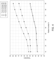
- FIG 4 shows a graph of the results of an experiment to investigate the relationship between temperature of a heat pipe and relative humidity in an oven.
- a heat pipe was arranged to extend partially inside a climate chamber representing an oven (and heretofore referred to as an oven).
- the oven was set to a specific temperature and relative humidity.
- the heat pipe comprised a bent portion located outside the oven, and a thermal sensor was placed at the bent portion to monitor the temperature thereof.
- the humidity inside the oven was then increased in 10% increments, with the temperature of the heat pipe being measured periodically as the humidity was increased.
- the temperature of the heat pipe was then plotted as a function of humidity.
- the experiment was repeated with the oven set at three different temperatures (60, 80 and 90 degrees Celsius).
- a quadratic curve was fitted to the steeper part of the curves shown in Figure 4 .
- Parameter Toven Parameter 90 ° C ⁇ 90 ⁇ Toven 10 ⁇ Parameter delta
- Parameter Toven is the parameter at a particular oven temperature
- Parameter 90 ⁇ C is the corresponding parameter at the 90 degree setting from equation (3)
- Toven is the oven temperature
- Parameter delta is the corresponding parameter in equation (5).
- a graph can be plotted which estimates the relative humidity in the oven, based on measurements of the temperature of the heat pipe and the oven. This graph is shown in Figure 5 , which depicts the temperature of the oven ("Toven”) against the temperature of the heat pipe at the bent portion ("Tcurve") at various relative humidity levels RH 10, RH 20, ..., RH 90.
- an oven temperature reading of 100 degrees Celsius and a heat pipe temperature reading of 80 degrees Celsius corresponds to an estimated relative humidity of around 50.
- the known relationship between heat pipe temperature and oven temperature can be used to estimate the actual water vapour concentration inside the oven inner cavity, and then the fluid supply can be controlled based upon the estimation to achieve a target water vapour concentration.
- the data represented in Figure 5 can be stored in a look-up table, and the control unit 7 can determine the actual humidity of the oven inner cavity 3 by receiving the temperature measurements from the temperature sensors 10a, 10c and finding the corresponding humidity in the look-up table. Humidity can then be related to molar fraction of water vapour, which may be a more useful way of representing the level of steam within the steam oven.
- control unit 7 can determine the actual humidity of the oven inner cavity 3 by additionally receiving the temperature measurements from the temperature sensor 10b. This is may be useful in the context of aircraft, where the ambient temperature on board the aircraft at high altitude may not correspond to standard temperature, and may change during the course of the flight.
- the thermal transport properties of the heat pipe may change depending on the air pressure in the exterior space and/or the water vapour concentration in the exterior space. This is particularly the case when the aerospace galley insert is located on an aircraft, since the humidity and pressure of an aircraft at high altitude will differ from standard humidity and pressure, and thus referencing a heat pipe at standard pressure and humidity may be less accurate.
- the data in Figures 4 and 5 which was taken at standard ambient pressure and humidity, may not accurately reflect the behaviour of a heat pipe at a cabin pressure and humidity.
- pressure and water vapour concentration sensors can be included in the aircraft galley insert as previously described, such that the control unit can estimate the humidity based additionally on these measurements. This can obtain a more reliable humidity estimation.
Landscapes
- Life Sciences & Earth Sciences (AREA)
- Engineering & Computer Science (AREA)
- Health & Medical Sciences (AREA)
- Chemical & Material Sciences (AREA)
- Physics & Mathematics (AREA)
- Biochemistry (AREA)
- General Health & Medical Sciences (AREA)
- General Physics & Mathematics (AREA)
- Immunology (AREA)
- Pathology (AREA)
- Analytical Chemistry (AREA)
- Food Science & Technology (AREA)
- Biomedical Technology (AREA)
- Aviation & Aerospace Engineering (AREA)
- Biophysics (AREA)
- Polymers & Plastics (AREA)
- Nutrition Science (AREA)
- Human Computer Interaction (AREA)
- Hematology (AREA)
- Molecular Biology (AREA)
- Urology & Nephrology (AREA)
- Medicinal Chemistry (AREA)
- Investigating Or Analyzing Materials Using Thermal Means (AREA)
Claims (15)
- Kücheneinsatz (1; 21) für die Luftfahrt, umfassend:einen Ofen (2), der einen inneren Ofenhohlraum (3) zum Aufnehmen von zuzubereitenden Nahrungsmitteln definiert;eine Fluidzufuhr (5) zum Zuführen von Fluid, das Wasser oder Wasserdampf umfasst, in den inneren Ofenhohlraum;einen Außenraum (4), der außerhalb des inneren Ofenhohlraums definiert ist;einen ersten Temperatursensor (10a) zum Erfassen einer ersten Temperatur in dem inneren Ofenhohlraum; undeine Steuereinheit (7), die dazu konfiguriert ist, die Fluidzufuhr zu steuern;gekennzeichnet durch:einen zweiten Temperatursensor (10b) zum Erfassen einer zweiten Temperatur in dem Außenraum;ein Wärmerohr (8; 28), das sich zwischen dem inneren Ofenhohlraum und dem Außenraum erstreckt; undeinen dritten Temperatursensor (10c) zum Erfassen einer dritten Temperatur des Wärmerohrs dort, wo es sich in den Außenraum erstreckt;wobei die Steuereinheit (7) dazu konfiguriert ist, eine Ist-Wasserdampfkonzentration in dem inneren Ofenhohlraum basierend auf der ersten, der zweiten und der dritten Temperatur zu bestimmen, und dazu konfiguriert ist, die Fluidzufuhr zu steuern, um die Ist-Wasserdampfkonzentration an eine Soll-Wasserdampfkonzentration anzupassen.
- Kücheneinsatz für die Luftfahrt nach Anspruch 1, wobei die Soll-Wasserdampfkonzentration ein Wasserdampf-Molanteil von mindestens 45 %, optional mindestens 60 % ist.
- Kücheneinsatz für die Luftfahrt nach Anspruch 1, wobei die Soll-Wasserdampfkonzentration ein Wasserdampf-Molanteil von 45-75 % ist.
- Kücheneinsatz für die Luftfahrt nach einem der vorhergehenden Ansprüche, wobei die Steuereinheit dazu konfiguriert ist, die Ist-Wasserdampfkonzentration basierend auf einem gemessenen Umgebungsluftdruck anzupassen.
- Kücheneinsatz für die Luftfahrt nach Anspruch 4, wobei die Steuereinheit einen Luftdrucksensor (11) zum Messen des Luftdrucks in dem Außenraum umfasst, um so den gemessenen Umgebungsluftdruck bereitzustellen.
- Kücheneinsatz für die Luftfahrt nach einem der vorhergehenden Ansprüche, wobei das Wärmerohr mindestens dort, wo es sich in den inneren Ofenhohlraum erstreckt, Titan umfasst.
- Kücheneinsatz für die Luftfahrt nach einem der vorhergehenden Ansprüche, wobei die Steuereinheit dazu konfiguriert ist, die Ist-Wasserdampfkonzentration in dem inneren Ofenhohlraum basierend auf einer gemessenen Wasserdampfkonzentration in dem Außenraum zu bestimmen, und wobei die Steuereinheit optional einen Wasserdampfkonzentrationssensor (12) zum Messen der Wasserdampfkonzentration in dem Außenraum umfasst, um so die gemessene Wasserdampfkonzentration bereitzustellen.
- Kücheneinsatz für die Luftfahrt nach einem der vorhergehenden Ansprüche, wobei das Wärmerohr einen ersten Schenkel (28a, 28b), der sich zwischen dem inneren Ofenhohlraum und dem Außenraum erstreckt, und einen zweiten Schenkel (28c), der sich in den Außenraum erstreckt und durch einen gebogenen Abschnitt (28d) mit dem ersten Schenkel verbunden ist, umfasst, wobei sich der zweite Schenkel mindestens teilweise von dem gebogenen Abschnitt nach oben erstreckt, und wobei optional der dritte Temperatursensor so angeordnet ist, dass er die Temperatur an dem gebogenen Abschnitt des Wärmerohrs misst.
- Kücheneinsatz für die Luftfahrt nach einem der vorhergehenden Ansprüche, wobei sich nicht mehr als 20 % der Länge des Wärmerohrs in dem inneren Ofenhohlraum befinden.
- Kücheneinsatz für die Luftfahrt nach einem der vorhergehenden Ansprüche, wobei das Wärmerohr einen Docht (14) umfasst.
- Verfahren zum Regeln der Wasserdampfkonzentration in einem Ofen (2) eines Kücheneinsatzes (1; 21) für die Luftfahrt, wobei der Ofen einen inneren Ofenhohlraum (3) darin zum Aufnehmen von zuzubereitenden Nahrungsmitteln definiert, wobei das Verfahren Folgendes umfasst:Erfassen einer ersten Temperatur in dem inneren Ofenhohlraum; undSteuern einer Zufuhr von Fluid in den inneren Ofenhohlraum,dadurch gekennzeichnet, dass der Kücheneinsatz für die Luftfahrt ein Wärmerohr (8; 28) aufweist, das sich zwischen dem inneren Ofenhohlraum und einem Außenraum (4) erstreckt, der außerhalb des inneren Ofenhohlraums definiert ist, wobei das Verfahren ferner Folgendes umfasst:Erfassen einer zweiten Temperatur in dem Außenraum;Erfassen einer dritten Temperatur des Wärmerohrs dort, wo es sich in den Außenraum erstreckt; undBestimmen einer Ist-Wasserdampfkonzentration in dem inneren Ofenhohlraum basierend auf der ersten, der zweiten und der dritten Temperatur;wobei das Steuern der Zufuhr von Fluid in den inneren Ofenhohlraum Steuern der Zufuhr von Fluid in den inneren Ofenhohlraum, um die Ist-Wasserdampfkonzentration an eine Soll-Wasserdampfkonzentration anzupassen, umfasst, wobei das Fluid Wasser oder Wasserdampf umfasst.
- Verfahren nach Anspruch 11, umfassend Messen eines Umgebungsluftdrucks und Anpassen der Ist-Wasserdampfkonzentration basierend auf dem gemessenen Umgebungsluftdruck.
- Verfahren nach Anspruch 11 oder 12, umfassend Messen einer Wasserdampfkonzentration in dem Außenraum und Bestimmen der Ist-Wasserdampfkonzentration in dem inneren Ofenhohlraum basierend auf der gemessenen Wasserdampfkonzentration in dem Außenraum.
- Verfahren nach einem der Ansprüche 11 bis 13, wobei das Wärmerohr einen ersten Schenkel (28a, 28b), der sich zwischen dem inneren Ofenhohlraum und dem Außenraum erstreckt, und einen zweiten Schenkel (28c), der sich in den Außenraum erstreckt und durch einen gebogenen Abschnitt (28d) mit dem ersten Schenkel verbunden ist, umfasst, wobei sich der zweite Schenkel mindestens teilweise von dem gebogenen Abschnitt nach oben erstreckt, und wobei optional die dritte Temperatur die Temperatur des gebogenen Abschnitts des Wärmerohrs ist.
- Verfahren nach einem der Ansprüche 11 bis 14, wobei das Wärmerohr einen Docht (14) umfasst.
Priority Applications (2)
| Application Number | Priority Date | Filing Date | Title |
|---|---|---|---|
| EP21182203.6A EP4112465B1 (de) | 2021-06-28 | 2021-06-28 | Kücheneinsatz mit ofen für die luftfahrt |
| US17/751,783 US12559236B2 (en) | 2021-06-28 | 2022-05-24 | Aerospace galley insert comprising oven |
Applications Claiming Priority (1)
| Application Number | Priority Date | Filing Date | Title |
|---|---|---|---|
| EP21182203.6A EP4112465B1 (de) | 2021-06-28 | 2021-06-28 | Kücheneinsatz mit ofen für die luftfahrt |
Publications (2)
| Publication Number | Publication Date |
|---|---|
| EP4112465A1 EP4112465A1 (de) | 2023-01-04 |
| EP4112465B1 true EP4112465B1 (de) | 2025-02-19 |
Family
ID=76707963
Family Applications (1)
| Application Number | Title | Priority Date | Filing Date |
|---|---|---|---|
| EP21182203.6A Active EP4112465B1 (de) | 2021-06-28 | 2021-06-28 | Kücheneinsatz mit ofen für die luftfahrt |
Country Status (2)
| Country | Link |
|---|---|
| US (1) | US12559236B2 (de) |
| EP (1) | EP4112465B1 (de) |
Families Citing this family (1)
| Publication number | Priority date | Publication date | Assignee | Title |
|---|---|---|---|---|
| EP4438479B1 (de) * | 2023-03-31 | 2026-03-11 | B/E Aerospace, Inc. | Flugzeugofen mit sicherheitsbetriebsmodus |
Family Cites Families (11)
| Publication number | Priority date | Publication date | Assignee | Title |
|---|---|---|---|---|
| US4557413A (en) * | 1984-04-11 | 1985-12-10 | Mcdonnell Douglas | Heat pipe fabrication |
| IT1258073B (it) * | 1992-04-29 | 1996-02-20 | Zanussi Elettromecc | Dispositivo di misura dell'umidita' per forni, in particolare forni dicottura di alimenti |
| DE102005048756A1 (de) * | 2005-10-10 | 2007-04-12 | Vereta Gmbh | Vorrichtung zur Messung der Kondensationstemperatur eines Gases |
| CN101055151A (zh) * | 2006-04-14 | 2007-10-17 | 富准精密工业(深圳)有限公司 | 热管 |
| KR101365879B1 (ko) | 2007-04-04 | 2014-02-21 | 에스펙 가부시키가이샤 | 습도계 및 노점계 |
| JP2010210118A (ja) * | 2009-03-09 | 2010-09-24 | Jamco Corp | 漏水防止用安全弁を備えた旅客機搭載用スチームオーブン |
| JP5615685B2 (ja) * | 2010-12-24 | 2014-10-29 | 株式会社ジャムコ | 航空機用スチームオーブン |
| US10481078B2 (en) | 2012-04-16 | 2019-11-19 | Espec Corp. | Hygrometer and temperature-humidity chamber provided with same |
| EP3365605B1 (de) * | 2015-10-22 | 2020-04-08 | Electrolux Appliances Aktiebolag | Verfahren und haushaltsgeräts zur feuchtigkeitskontrolle |
| JP6457967B2 (ja) | 2016-03-25 | 2019-01-23 | エスペック株式会社 | 湿度計及び環境試験装置 |
| WO2020074476A1 (de) * | 2018-10-10 | 2020-04-16 | BSH Hausgeräte GmbH | Haushalts-dampfgargerät und verfahren zum betreiben eines haushalts-dampfgargeräts |
-
2021
- 2021-06-28 EP EP21182203.6A patent/EP4112465B1/de active Active
-
2022
- 2022-05-24 US US17/751,783 patent/US12559236B2/en active Active
Also Published As
| Publication number | Publication date |
|---|---|
| EP4112465A1 (de) | 2023-01-04 |
| US20220411067A1 (en) | 2022-12-29 |
| US12559236B2 (en) | 2026-02-24 |
Similar Documents
| Publication | Publication Date | Title |
|---|---|---|
| US20250155297A1 (en) | Wet bulb temperature sensor system and method for direct measurement of wet bulb temperature in an oven | |
| US11066746B1 (en) | Liquid material vaporization and supply device, and control program | |
| Taler et al. | Monitoring of thermal stresses in pressure components based on the wall temperature measurement | |
| ITPN20100026A1 (it) | Forno per cottura a convenzione a vapore dotato di sistema per la rilevazione e regolazione dell'umidita' | |
| US12559236B2 (en) | Aerospace galley insert comprising oven | |
| BRPI0904576B1 (pt) | Método para controlar um sistema de aquecimento indutivo de um fogão e dispositivo de cozimento | |
| CN102261633B (zh) | 具有蒸汽产生功能的烧煮装置 | |
| TW201344185A (zh) | 濕度計及具有該濕度計之恒溫恒濕槽 | |
| JP6527950B2 (ja) | 貫流蒸気発生器を運転するための制御方法 | |
| CN204830058U (zh) | 具有自动火力标定功能的燃气式烹调系统 | |
| CZ2001222A3 (cs) | Způsob teplotní kompenzace teplotního čidla | |
| TWI614454B (zh) | 具有自動火力標定功能的燃氣式烹調系統及燃氣式烹調系統的自動火力標定方法 | |
| CN113056639B (zh) | 用于强制流动废热蒸汽发生器的给水控制 | |
| CN106322447B (zh) | 具有自动火力标定功能的燃气式烹调系统 | |
| JP6256095B2 (ja) | スケール付着判定装置 | |
| JP5896766B2 (ja) | ガスタービンの制御装置、ガスタービン、及びガスタービンの制御方法 | |
| JP6209988B2 (ja) | スケール付着判定装置 | |
| CN211148550U (zh) | 一种用于定氮仪的蒸汽发生装置 | |
| CN102246017A (zh) | 估算涡轮喷气发动机中流体温度的方法和系统 | |
| US12478208B2 (en) | Cooking adjustment system | |
| CN106257142B (zh) | 燃气式烹调系统的自动火力标定方法 | |
| KR100689153B1 (ko) | 가열로에서의 슬라브 온도 예측 방법. | |
| Dementjev et al. | Variation of the temperature factor of models on a ballistic range | |
| Kypuros et al. | Improved temperature dynamic model of turbine subcomponents for facilitation of generalized tip clearance control | |
| HK40066699A (zh) | 湿球温度传感器系统以及用於直接测量烤箱中的湿球温度的方法 |
Legal Events
| Date | Code | Title | Description |
|---|---|---|---|
| PUAI | Public reference made under article 153(3) epc to a published international application that has entered the european phase |
Free format text: ORIGINAL CODE: 0009012 |
|
| STAA | Information on the status of an ep patent application or granted ep patent |
Free format text: STATUS: THE APPLICATION HAS BEEN PUBLISHED |
|
| AK | Designated contracting states |
Kind code of ref document: A1 Designated state(s): AL AT BE BG CH CY CZ DE DK EE ES FI FR GB GR HR HU IE IS IT LI LT LU LV MC MK MT NL NO PL PT RO RS SE SI SK SM TR |
|
| STAA | Information on the status of an ep patent application or granted ep patent |
Free format text: STATUS: REQUEST FOR EXAMINATION WAS MADE |
|
| 17P | Request for examination filed |
Effective date: 20230704 |
|
| RBV | Designated contracting states (corrected) |
Designated state(s): AL AT BE BG CH CY CZ DE DK EE ES FI FR GB GR HR HU IE IS IT LI LT LU LV MC MK MT NL NO PL PT RO RS SE SI SK SM TR |
|
| P01 | Opt-out of the competence of the unified patent court (upc) registered |
Effective date: 20230922 |
|
| GRAP | Despatch of communication of intention to grant a patent |
Free format text: ORIGINAL CODE: EPIDOSNIGR1 |
|
| STAA | Information on the status of an ep patent application or granted ep patent |
Free format text: STATUS: GRANT OF PATENT IS INTENDED |
|
| RIC1 | Information provided on ipc code assigned before grant |
Ipc: F24C 15/32 20060101ALN20240904BHEP Ipc: F24C 15/00 20060101ALN20240904BHEP Ipc: G01N 33/487 20060101ALI20240904BHEP Ipc: A21B 3/04 20060101ALI20240904BHEP Ipc: B64D 11/04 20060101AFI20240904BHEP |
|
| INTG | Intention to grant announced |
Effective date: 20240913 |
|
| GRAS | Grant fee paid |
Free format text: ORIGINAL CODE: EPIDOSNIGR3 |
|
| GRAA | (expected) grant |
Free format text: ORIGINAL CODE: 0009210 |
|
| STAA | Information on the status of an ep patent application or granted ep patent |
Free format text: STATUS: THE PATENT HAS BEEN GRANTED |
|
| AK | Designated contracting states |
Kind code of ref document: B1 Designated state(s): AL AT BE BG CH CY CZ DE DK EE ES FI FR GB GR HR HU IE IS IT LI LT LU LV MC MK MT NL NO PL PT RO RS SE SI SK SM TR |
|
| REG | Reference to a national code |
Ref country code: GB Ref legal event code: FG4D |
|
| REG | Reference to a national code |
Ref country code: CH Ref legal event code: EP |
|
| REG | Reference to a national code |
Ref country code: IE Ref legal event code: FG4D |
|
| REG | Reference to a national code |
Ref country code: DE Ref legal event code: R096 Ref document number: 602021026261 Country of ref document: DE |
|
| REG | Reference to a national code |
Ref country code: NL Ref legal event code: MP Effective date: 20250219 |
|
| PG25 | Lapsed in a contracting state [announced via postgrant information from national office to epo] |
Ref country code: RS Free format text: LAPSE BECAUSE OF FAILURE TO SUBMIT A TRANSLATION OF THE DESCRIPTION OR TO PAY THE FEE WITHIN THE PRESCRIBED TIME-LIMIT Effective date: 20250519 |
|
| PG25 | Lapsed in a contracting state [announced via postgrant information from national office to epo] |
Ref country code: FI Free format text: LAPSE BECAUSE OF FAILURE TO SUBMIT A TRANSLATION OF THE DESCRIPTION OR TO PAY THE FEE WITHIN THE PRESCRIBED TIME-LIMIT Effective date: 20250219 |
|
| PG25 | Lapsed in a contracting state [announced via postgrant information from national office to epo] |
Ref country code: PL Free format text: LAPSE BECAUSE OF FAILURE TO SUBMIT A TRANSLATION OF THE DESCRIPTION OR TO PAY THE FEE WITHIN THE PRESCRIBED TIME-LIMIT Effective date: 20250219 |
|
| PGFP | Annual fee paid to national office [announced via postgrant information from national office to epo] |
Ref country code: DE Payment date: 20250520 Year of fee payment: 5 |
|
| PG25 | Lapsed in a contracting state [announced via postgrant information from national office to epo] |
Ref country code: ES Free format text: LAPSE BECAUSE OF FAILURE TO SUBMIT A TRANSLATION OF THE DESCRIPTION OR TO PAY THE FEE WITHIN THE PRESCRIBED TIME-LIMIT Effective date: 20250219 |
|
| PGFP | Annual fee paid to national office [announced via postgrant information from national office to epo] |
Ref country code: GB Payment date: 20250520 Year of fee payment: 5 |
|
| REG | Reference to a national code |
Ref country code: LT Ref legal event code: MG9D |
|
| PG25 | Lapsed in a contracting state [announced via postgrant information from national office to epo] |
Ref country code: NO Free format text: LAPSE BECAUSE OF FAILURE TO SUBMIT A TRANSLATION OF THE DESCRIPTION OR TO PAY THE FEE WITHIN THE PRESCRIBED TIME-LIMIT Effective date: 20250519 Ref country code: IS Free format text: LAPSE BECAUSE OF FAILURE TO SUBMIT A TRANSLATION OF THE DESCRIPTION OR TO PAY THE FEE WITHIN THE PRESCRIBED TIME-LIMIT Effective date: 20250619 |
|
| PG25 | Lapsed in a contracting state [announced via postgrant information from national office to epo] |
Ref country code: NL Free format text: LAPSE BECAUSE OF FAILURE TO SUBMIT A TRANSLATION OF THE DESCRIPTION OR TO PAY THE FEE WITHIN THE PRESCRIBED TIME-LIMIT Effective date: 20250219 |
|
| PG25 | Lapsed in a contracting state [announced via postgrant information from national office to epo] |
Ref country code: HR Free format text: LAPSE BECAUSE OF FAILURE TO SUBMIT A TRANSLATION OF THE DESCRIPTION OR TO PAY THE FEE WITHIN THE PRESCRIBED TIME-LIMIT Effective date: 20250219 |
|
| PG25 | Lapsed in a contracting state [announced via postgrant information from national office to epo] |
Ref country code: LV Free format text: LAPSE BECAUSE OF FAILURE TO SUBMIT A TRANSLATION OF THE DESCRIPTION OR TO PAY THE FEE WITHIN THE PRESCRIBED TIME-LIMIT Effective date: 20250219 Ref country code: PT Free format text: LAPSE BECAUSE OF FAILURE TO SUBMIT A TRANSLATION OF THE DESCRIPTION OR TO PAY THE FEE WITHIN THE PRESCRIBED TIME-LIMIT Effective date: 20250620 |
|
| PGFP | Annual fee paid to national office [announced via postgrant information from national office to epo] |
Ref country code: FR Payment date: 20250520 Year of fee payment: 5 |
|
| PG25 | Lapsed in a contracting state [announced via postgrant information from national office to epo] |
Ref country code: BG Free format text: LAPSE BECAUSE OF FAILURE TO SUBMIT A TRANSLATION OF THE DESCRIPTION OR TO PAY THE FEE WITHIN THE PRESCRIBED TIME-LIMIT Effective date: 20250219 Ref country code: GR Free format text: LAPSE BECAUSE OF FAILURE TO SUBMIT A TRANSLATION OF THE DESCRIPTION OR TO PAY THE FEE WITHIN THE PRESCRIBED TIME-LIMIT Effective date: 20250520 |
|
| REG | Reference to a national code |
Ref country code: AT Ref legal event code: MK05 Ref document number: 1768086 Country of ref document: AT Kind code of ref document: T Effective date: 20250219 |
|
| PG25 | Lapsed in a contracting state [announced via postgrant information from national office to epo] |
Ref country code: SE Free format text: LAPSE BECAUSE OF FAILURE TO SUBMIT A TRANSLATION OF THE DESCRIPTION OR TO PAY THE FEE WITHIN THE PRESCRIBED TIME-LIMIT Effective date: 20250219 |
|
| PG25 | Lapsed in a contracting state [announced via postgrant information from national office to epo] |
Ref country code: SM Free format text: LAPSE BECAUSE OF FAILURE TO SUBMIT A TRANSLATION OF THE DESCRIPTION OR TO PAY THE FEE WITHIN THE PRESCRIBED TIME-LIMIT Effective date: 20250219 |
|
| PG25 | Lapsed in a contracting state [announced via postgrant information from national office to epo] |
Ref country code: DK Free format text: LAPSE BECAUSE OF FAILURE TO SUBMIT A TRANSLATION OF THE DESCRIPTION OR TO PAY THE FEE WITHIN THE PRESCRIBED TIME-LIMIT Effective date: 20250219 |
|
| PG25 | Lapsed in a contracting state [announced via postgrant information from national office to epo] |
Ref country code: IT Free format text: LAPSE BECAUSE OF FAILURE TO SUBMIT A TRANSLATION OF THE DESCRIPTION OR TO PAY THE FEE WITHIN THE PRESCRIBED TIME-LIMIT Effective date: 20250219 |
|
| PG25 | Lapsed in a contracting state [announced via postgrant information from national office to epo] |
Ref country code: AT Free format text: LAPSE BECAUSE OF FAILURE TO SUBMIT A TRANSLATION OF THE DESCRIPTION OR TO PAY THE FEE WITHIN THE PRESCRIBED TIME-LIMIT Effective date: 20250219 |
|
| PG25 | Lapsed in a contracting state [announced via postgrant information from national office to epo] |
Ref country code: CZ Free format text: LAPSE BECAUSE OF FAILURE TO SUBMIT A TRANSLATION OF THE DESCRIPTION OR TO PAY THE FEE WITHIN THE PRESCRIBED TIME-LIMIT Effective date: 20250219 Ref country code: EE Free format text: LAPSE BECAUSE OF FAILURE TO SUBMIT A TRANSLATION OF THE DESCRIPTION OR TO PAY THE FEE WITHIN THE PRESCRIBED TIME-LIMIT Effective date: 20250219 |
|
| PG25 | Lapsed in a contracting state [announced via postgrant information from national office to epo] |
Ref country code: RO Free format text: LAPSE BECAUSE OF FAILURE TO SUBMIT A TRANSLATION OF THE DESCRIPTION OR TO PAY THE FEE WITHIN THE PRESCRIBED TIME-LIMIT Effective date: 20250219 |
|
| PG25 | Lapsed in a contracting state [announced via postgrant information from national office to epo] |
Ref country code: SK Free format text: LAPSE BECAUSE OF FAILURE TO SUBMIT A TRANSLATION OF THE DESCRIPTION OR TO PAY THE FEE WITHIN THE PRESCRIBED TIME-LIMIT Effective date: 20250219 |
|
| REG | Reference to a national code |
Ref country code: DE Ref legal event code: R097 Ref document number: 602021026261 Country of ref document: DE |
|
| PLBE | No opposition filed within time limit |
Free format text: ORIGINAL CODE: 0009261 |
|
| STAA | Information on the status of an ep patent application or granted ep patent |
Free format text: STATUS: NO OPPOSITION FILED WITHIN TIME LIMIT |
|
| REG | Reference to a national code |
Ref country code: CH Ref legal event code: L10 Free format text: ST27 STATUS EVENT CODE: U-0-0-L10-L00 (AS PROVIDED BY THE NATIONAL OFFICE) Effective date: 20251231 |
|
| REG | Reference to a national code |
Ref country code: CH Ref legal event code: H13 Free format text: ST27 STATUS EVENT CODE: U-0-0-H10-H13 (AS PROVIDED BY THE NATIONAL OFFICE) Effective date: 20260127 |
|
| 26N | No opposition filed |
Effective date: 20251120 |
|
| PG25 | Lapsed in a contracting state [announced via postgrant information from national office to epo] |
Ref country code: MC Free format text: LAPSE BECAUSE OF FAILURE TO SUBMIT A TRANSLATION OF THE DESCRIPTION OR TO PAY THE FEE WITHIN THE PRESCRIBED TIME-LIMIT Effective date: 20250219 |
|
| PG25 | Lapsed in a contracting state [announced via postgrant information from national office to epo] |
Ref country code: LU Free format text: LAPSE BECAUSE OF NON-PAYMENT OF DUE FEES Effective date: 20250628 |
|
| REG | Reference to a national code |
Ref country code: BE Ref legal event code: MM Effective date: 20250630 |
|
| PG25 | Lapsed in a contracting state [announced via postgrant information from national office to epo] |
Ref country code: IE Free format text: LAPSE BECAUSE OF NON-PAYMENT OF DUE FEES Effective date: 20250628 |
|
| PG25 | Lapsed in a contracting state [announced via postgrant information from national office to epo] |
Ref country code: BE Free format text: LAPSE BECAUSE OF NON-PAYMENT OF DUE FEES Effective date: 20250630 |
|
| PG25 | Lapsed in a contracting state [announced via postgrant information from national office to epo] |
Ref country code: CH Free format text: LAPSE BECAUSE OF NON-PAYMENT OF DUE FEES Effective date: 20250630 |