EP4112279A1 - Verfahren und bauteilsegment zur herstellung eines versteiften flächigen bauteils für luftfahrzeuge, sowie luftfahrzeug - Google Patents
Verfahren und bauteilsegment zur herstellung eines versteiften flächigen bauteils für luftfahrzeuge, sowie luftfahrzeug Download PDFInfo
- Publication number
- EP4112279A1 EP4112279A1 EP21182912.2A EP21182912A EP4112279A1 EP 4112279 A1 EP4112279 A1 EP 4112279A1 EP 21182912 A EP21182912 A EP 21182912A EP 4112279 A1 EP4112279 A1 EP 4112279A1
- Authority
- EP
- European Patent Office
- Prior art keywords
- component
- profile
- segments
- segment
- areas
- Prior art date
- Legal status (The legal status is an assumption and is not a legal conclusion. Google has not performed a legal analysis and makes no representation as to the accuracy of the status listed.)
- Pending
Links
Images


Classifications
-
- B—PERFORMING OPERATIONS; TRANSPORTING
- B29—WORKING OF PLASTICS; WORKING OF SUBSTANCES IN A PLASTIC STATE IN GENERAL
- B29C—SHAPING OR JOINING OF PLASTICS; SHAPING OF MATERIAL IN A PLASTIC STATE, NOT OTHERWISE PROVIDED FOR; AFTER-TREATMENT OF THE SHAPED PRODUCTS, e.g. REPAIRING
- B29C66/00—General aspects of processes or apparatus for joining preformed parts
- B29C66/70—General aspects of processes or apparatus for joining preformed parts characterised by the composition, physical properties or the structure of the material of the parts to be joined; Joining with non-plastics material
- B29C66/72—General aspects of processes or apparatus for joining preformed parts characterised by the composition, physical properties or the structure of the material of the parts to be joined; Joining with non-plastics material characterised by the structure of the material of the parts to be joined
- B29C66/721—Fibre-reinforced materials
-
- B—PERFORMING OPERATIONS; TRANSPORTING
- B29—WORKING OF PLASTICS; WORKING OF SUBSTANCES IN A PLASTIC STATE IN GENERAL
- B29C—SHAPING OR JOINING OF PLASTICS; SHAPING OF MATERIAL IN A PLASTIC STATE, NOT OTHERWISE PROVIDED FOR; AFTER-TREATMENT OF THE SHAPED PRODUCTS, e.g. REPAIRING
- B29C65/00—Joining or sealing of preformed parts, e.g. welding of plastics materials; Apparatus therefor
- B29C65/02—Joining or sealing of preformed parts, e.g. welding of plastics materials; Apparatus therefor by heating, with or without pressure
-
- B—PERFORMING OPERATIONS; TRANSPORTING
- B29—WORKING OF PLASTICS; WORKING OF SUBSTANCES IN A PLASTIC STATE IN GENERAL
- B29C—SHAPING OR JOINING OF PLASTICS; SHAPING OF MATERIAL IN A PLASTIC STATE, NOT OTHERWISE PROVIDED FOR; AFTER-TREATMENT OF THE SHAPED PRODUCTS, e.g. REPAIRING
- B29C66/00—General aspects of processes or apparatus for joining preformed parts
- B29C66/01—General aspects dealing with the joint area or with the area to be joined
- B29C66/05—Particular design of joint configurations
- B29C66/10—Particular design of joint configurations particular design of the joint cross-sections
- B29C66/11—Joint cross-sections comprising a single joint-segment, i.e. one of the parts to be joined comprising a single joint-segment in the joint cross-section
- B29C66/112—Single lapped joints
-
- B—PERFORMING OPERATIONS; TRANSPORTING
- B29—WORKING OF PLASTICS; WORKING OF SUBSTANCES IN A PLASTIC STATE IN GENERAL
- B29C—SHAPING OR JOINING OF PLASTICS; SHAPING OF MATERIAL IN A PLASTIC STATE, NOT OTHERWISE PROVIDED FOR; AFTER-TREATMENT OF THE SHAPED PRODUCTS, e.g. REPAIRING
- B29C66/00—General aspects of processes or apparatus for joining preformed parts
- B29C66/01—General aspects dealing with the joint area or with the area to be joined
- B29C66/05—Particular design of joint configurations
- B29C66/10—Particular design of joint configurations particular design of the joint cross-sections
- B29C66/13—Single flanged joints; Fin-type joints; Single hem joints; Edge joints; Interpenetrating fingered joints; Other specific particular designs of joint cross-sections not provided for in groups B29C66/11 - B29C66/12
- B29C66/131—Single flanged joints, i.e. one of the parts to be joined being rigid and flanged in the joint area
-
- B—PERFORMING OPERATIONS; TRANSPORTING
- B29—WORKING OF PLASTICS; WORKING OF SUBSTANCES IN A PLASTIC STATE IN GENERAL
- B29C—SHAPING OR JOINING OF PLASTICS; SHAPING OF MATERIAL IN A PLASTIC STATE, NOT OTHERWISE PROVIDED FOR; AFTER-TREATMENT OF THE SHAPED PRODUCTS, e.g. REPAIRING
- B29C66/00—General aspects of processes or apparatus for joining preformed parts
- B29C66/50—General aspects of joining tubular articles; General aspects of joining long products, i.e. bars or profiled elements; General aspects of joining single elements to tubular articles, hollow articles or bars; General aspects of joining several hollow-preforms to form hollow or tubular articles
- B29C66/51—Joining tubular articles, profiled elements or bars; Joining single elements to tubular articles, hollow articles or bars; Joining several hollow-preforms to form hollow or tubular articles
- B29C66/54—Joining several hollow-preforms, e.g. half-shells, to form hollow articles, e.g. for making balls, containers; Joining several hollow-preforms, e.g. half-cylinders, to form tubular articles
- B29C66/543—Joining several hollow-preforms, e.g. half-shells, to form hollow articles, e.g. for making balls, containers; Joining several hollow-preforms, e.g. half-cylinders, to form tubular articles joining more than two hollow-preforms to form said hollow articles
-
- B—PERFORMING OPERATIONS; TRANSPORTING
- B29—WORKING OF PLASTICS; WORKING OF SUBSTANCES IN A PLASTIC STATE IN GENERAL
- B29C—SHAPING OR JOINING OF PLASTICS; SHAPING OF MATERIAL IN A PLASTIC STATE, NOT OTHERWISE PROVIDED FOR; AFTER-TREATMENT OF THE SHAPED PRODUCTS, e.g. REPAIRING
- B29C66/00—General aspects of processes or apparatus for joining preformed parts
- B29C66/70—General aspects of processes or apparatus for joining preformed parts characterised by the composition, physical properties or the structure of the material of the parts to be joined; Joining with non-plastics material
- B29C66/73—General aspects of processes or apparatus for joining preformed parts characterised by the composition, physical properties or the structure of the material of the parts to be joined; Joining with non-plastics material characterised by the intensive physical properties of the material of the parts to be joined, by the optical properties of the material of the parts to be joined, by the extensive physical properties of the parts to be joined, by the state of the material of the parts to be joined or by the material of the parts to be joined being a thermoplastic or a thermoset
- B29C66/739—General aspects of processes or apparatus for joining preformed parts characterised by the composition, physical properties or the structure of the material of the parts to be joined; Joining with non-plastics material characterised by the intensive physical properties of the material of the parts to be joined, by the optical properties of the material of the parts to be joined, by the extensive physical properties of the parts to be joined, by the state of the material of the parts to be joined or by the material of the parts to be joined being a thermoplastic or a thermoset characterised by the material of the parts to be joined being a thermoplastic or a thermoset
- B29C66/7392—General aspects of processes or apparatus for joining preformed parts characterised by the composition, physical properties or the structure of the material of the parts to be joined; Joining with non-plastics material characterised by the intensive physical properties of the material of the parts to be joined, by the optical properties of the material of the parts to be joined, by the extensive physical properties of the parts to be joined, by the state of the material of the parts to be joined or by the material of the parts to be joined being a thermoplastic or a thermoset characterised by the material of the parts to be joined being a thermoplastic or a thermoset characterised by the material of at least one of the parts being a thermoplastic
- B29C66/73921—General aspects of processes or apparatus for joining preformed parts characterised by the composition, physical properties or the structure of the material of the parts to be joined; Joining with non-plastics material characterised by the intensive physical properties of the material of the parts to be joined, by the optical properties of the material of the parts to be joined, by the extensive physical properties of the parts to be joined, by the state of the material of the parts to be joined or by the material of the parts to be joined being a thermoplastic or a thermoset characterised by the material of the parts to be joined being a thermoplastic or a thermoset characterised by the material of at least one of the parts being a thermoplastic characterised by the materials of both parts being thermoplastics
-
- B—PERFORMING OPERATIONS; TRANSPORTING
- B64—AIRCRAFT; AVIATION; COSMONAUTICS
- B64C—AEROPLANES; HELICOPTERS
- B64C1/00—Fuselages; Constructional features common to fuselages, wings, stabilising surfaces or the like
- B64C1/06—Frames; Stringers; Longerons ; Fuselage sections
- B64C1/064—Stringers; Longerons
-
- B—PERFORMING OPERATIONS; TRANSPORTING
- B64—AIRCRAFT; AVIATION; COSMONAUTICS
- B64C—AEROPLANES; HELICOPTERS
- B64C1/00—Fuselages; Constructional features common to fuselages, wings, stabilising surfaces or the like
- B64C1/06—Frames; Stringers; Longerons ; Fuselage sections
- B64C1/12—Construction or attachment of skin panels
-
- B—PERFORMING OPERATIONS; TRANSPORTING
- B64—AIRCRAFT; AVIATION; COSMONAUTICS
- B64C—AEROPLANES; HELICOPTERS
- B64C3/00—Wings
- B64C3/18—Spars; Ribs; Stringers
- B64C3/182—Stringers, longerons
-
- B—PERFORMING OPERATIONS; TRANSPORTING
- B64—AIRCRAFT; AVIATION; COSMONAUTICS
- B64C—AEROPLANES; HELICOPTERS
- B64C3/00—Wings
- B64C3/26—Construction, shape, or attachment of separate skins, e.g. panels
-
- B—PERFORMING OPERATIONS; TRANSPORTING
- B29—WORKING OF PLASTICS; WORKING OF SUBSTANCES IN A PLASTIC STATE IN GENERAL
- B29C—SHAPING OR JOINING OF PLASTICS; SHAPING OF MATERIAL IN A PLASTIC STATE, NOT OTHERWISE PROVIDED FOR; AFTER-TREATMENT OF THE SHAPED PRODUCTS, e.g. REPAIRING
- B29C65/00—Joining or sealing of preformed parts, e.g. welding of plastics materials; Apparatus therefor
- B29C65/02—Joining or sealing of preformed parts, e.g. welding of plastics materials; Apparatus therefor by heating, with or without pressure
- B29C65/08—Joining or sealing of preformed parts, e.g. welding of plastics materials; Apparatus therefor by heating, with or without pressure using ultrasonic vibrations
-
- B—PERFORMING OPERATIONS; TRANSPORTING
- B29—WORKING OF PLASTICS; WORKING OF SUBSTANCES IN A PLASTIC STATE IN GENERAL
- B29C—SHAPING OR JOINING OF PLASTICS; SHAPING OF MATERIAL IN A PLASTIC STATE, NOT OTHERWISE PROVIDED FOR; AFTER-TREATMENT OF THE SHAPED PRODUCTS, e.g. REPAIRING
- B29C65/00—Joining or sealing of preformed parts, e.g. welding of plastics materials; Apparatus therefor
- B29C65/02—Joining or sealing of preformed parts, e.g. welding of plastics materials; Apparatus therefor by heating, with or without pressure
- B29C65/14—Joining or sealing of preformed parts, e.g. welding of plastics materials; Apparatus therefor by heating, with or without pressure using wave energy, i.e. electromagnetic radiation, or particle radiation
- B29C65/1403—Joining or sealing of preformed parts, e.g. welding of plastics materials; Apparatus therefor by heating, with or without pressure using wave energy, i.e. electromagnetic radiation, or particle radiation characterised by the type of electromagnetic or particle radiation
- B29C65/1412—Infrared [IR] radiation
-
- B—PERFORMING OPERATIONS; TRANSPORTING
- B29—WORKING OF PLASTICS; WORKING OF SUBSTANCES IN A PLASTIC STATE IN GENERAL
- B29C—SHAPING OR JOINING OF PLASTICS; SHAPING OF MATERIAL IN A PLASTIC STATE, NOT OTHERWISE PROVIDED FOR; AFTER-TREATMENT OF THE SHAPED PRODUCTS, e.g. REPAIRING
- B29C65/00—Joining or sealing of preformed parts, e.g. welding of plastics materials; Apparatus therefor
- B29C65/02—Joining or sealing of preformed parts, e.g. welding of plastics materials; Apparatus therefor by heating, with or without pressure
- B29C65/14—Joining or sealing of preformed parts, e.g. welding of plastics materials; Apparatus therefor by heating, with or without pressure using wave energy, i.e. electromagnetic radiation, or particle radiation
- B29C65/16—Laser beams
-
- B—PERFORMING OPERATIONS; TRANSPORTING
- B29—WORKING OF PLASTICS; WORKING OF SUBSTANCES IN A PLASTIC STATE IN GENERAL
- B29C—SHAPING OR JOINING OF PLASTICS; SHAPING OF MATERIAL IN A PLASTIC STATE, NOT OTHERWISE PROVIDED FOR; AFTER-TREATMENT OF THE SHAPED PRODUCTS, e.g. REPAIRING
- B29C66/00—General aspects of processes or apparatus for joining preformed parts
- B29C66/70—General aspects of processes or apparatus for joining preformed parts characterised by the composition, physical properties or the structure of the material of the parts to be joined; Joining with non-plastics material
- B29C66/71—General aspects of processes or apparatus for joining preformed parts characterised by the composition, physical properties or the structure of the material of the parts to be joined; Joining with non-plastics material characterised by the composition of the plastics material of the parts to be joined
-
- B—PERFORMING OPERATIONS; TRANSPORTING
- B29—WORKING OF PLASTICS; WORKING OF SUBSTANCES IN A PLASTIC STATE IN GENERAL
- B29C—SHAPING OR JOINING OF PLASTICS; SHAPING OF MATERIAL IN A PLASTIC STATE, NOT OTHERWISE PROVIDED FOR; AFTER-TREATMENT OF THE SHAPED PRODUCTS, e.g. REPAIRING
- B29C66/00—General aspects of processes or apparatus for joining preformed parts
- B29C66/70—General aspects of processes or apparatus for joining preformed parts characterised by the composition, physical properties or the structure of the material of the parts to be joined; Joining with non-plastics material
- B29C66/72—General aspects of processes or apparatus for joining preformed parts characterised by the composition, physical properties or the structure of the material of the parts to be joined; Joining with non-plastics material characterised by the structure of the material of the parts to be joined
- B29C66/721—Fibre-reinforced materials
- B29C66/7212—Fibre-reinforced materials characterised by the composition of the fibres
-
- B—PERFORMING OPERATIONS; TRANSPORTING
- B29—WORKING OF PLASTICS; WORKING OF SUBSTANCES IN A PLASTIC STATE IN GENERAL
- B29C—SHAPING OR JOINING OF PLASTICS; SHAPING OF MATERIAL IN A PLASTIC STATE, NOT OTHERWISE PROVIDED FOR; AFTER-TREATMENT OF THE SHAPED PRODUCTS, e.g. REPAIRING
- B29C66/00—General aspects of processes or apparatus for joining preformed parts
- B29C66/70—General aspects of processes or apparatus for joining preformed parts characterised by the composition, physical properties or the structure of the material of the parts to be joined; Joining with non-plastics material
- B29C66/73—General aspects of processes or apparatus for joining preformed parts characterised by the composition, physical properties or the structure of the material of the parts to be joined; Joining with non-plastics material characterised by the intensive physical properties of the material of the parts to be joined, by the optical properties of the material of the parts to be joined, by the extensive physical properties of the parts to be joined, by the state of the material of the parts to be joined or by the material of the parts to be joined being a thermoplastic or a thermoset
- B29C66/731—General aspects of processes or apparatus for joining preformed parts characterised by the composition, physical properties or the structure of the material of the parts to be joined; Joining with non-plastics material characterised by the intensive physical properties of the material of the parts to be joined, by the optical properties of the material of the parts to be joined, by the extensive physical properties of the parts to be joined, by the state of the material of the parts to be joined or by the material of the parts to be joined being a thermoplastic or a thermoset characterised by the intensive physical properties of the material of the parts to be joined
- B29C66/7311—Thermal properties
- B29C66/73115—Melting point
-
- B—PERFORMING OPERATIONS; TRANSPORTING
- B29—WORKING OF PLASTICS; WORKING OF SUBSTANCES IN A PLASTIC STATE IN GENERAL
- B29C—SHAPING OR JOINING OF PLASTICS; SHAPING OF MATERIAL IN A PLASTIC STATE, NOT OTHERWISE PROVIDED FOR; AFTER-TREATMENT OF THE SHAPED PRODUCTS, e.g. REPAIRING
- B29C66/00—General aspects of processes or apparatus for joining preformed parts
- B29C66/70—General aspects of processes or apparatus for joining preformed parts characterised by the composition, physical properties or the structure of the material of the parts to be joined; Joining with non-plastics material
- B29C66/73—General aspects of processes or apparatus for joining preformed parts characterised by the composition, physical properties or the structure of the material of the parts to be joined; Joining with non-plastics material characterised by the intensive physical properties of the material of the parts to be joined, by the optical properties of the material of the parts to be joined, by the extensive physical properties of the parts to be joined, by the state of the material of the parts to be joined or by the material of the parts to be joined being a thermoplastic or a thermoset
- B29C66/737—General aspects of processes or apparatus for joining preformed parts characterised by the composition, physical properties or the structure of the material of the parts to be joined; Joining with non-plastics material characterised by the intensive physical properties of the material of the parts to be joined, by the optical properties of the material of the parts to be joined, by the extensive physical properties of the parts to be joined, by the state of the material of the parts to be joined or by the material of the parts to be joined being a thermoplastic or a thermoset characterised by the state of the material of the parts to be joined
- B29C66/7377—General aspects of processes or apparatus for joining preformed parts characterised by the composition, physical properties or the structure of the material of the parts to be joined; Joining with non-plastics material characterised by the intensive physical properties of the material of the parts to be joined, by the optical properties of the material of the parts to be joined, by the extensive physical properties of the parts to be joined, by the state of the material of the parts to be joined or by the material of the parts to be joined being a thermoplastic or a thermoset characterised by the state of the material of the parts to be joined amorphous, semi-crystalline or crystalline
- B29C66/73773—General aspects of processes or apparatus for joining preformed parts characterised by the composition, physical properties or the structure of the material of the parts to be joined; Joining with non-plastics material characterised by the intensive physical properties of the material of the parts to be joined, by the optical properties of the material of the parts to be joined, by the extensive physical properties of the parts to be joined, by the state of the material of the parts to be joined or by the material of the parts to be joined being a thermoplastic or a thermoset characterised by the state of the material of the parts to be joined amorphous, semi-crystalline or crystalline the to-be-joined area of at least one of the parts to be joined being semi-crystalline
- B29C66/73774—General aspects of processes or apparatus for joining preformed parts characterised by the composition, physical properties or the structure of the material of the parts to be joined; Joining with non-plastics material characterised by the intensive physical properties of the material of the parts to be joined, by the optical properties of the material of the parts to be joined, by the extensive physical properties of the parts to be joined, by the state of the material of the parts to be joined or by the material of the parts to be joined being a thermoplastic or a thermoset characterised by the state of the material of the parts to be joined amorphous, semi-crystalline or crystalline the to-be-joined area of at least one of the parts to be joined being semi-crystalline the to-be-joined areas of both parts to be joined being semi-crystalline
-
- B—PERFORMING OPERATIONS; TRANSPORTING
- B29—WORKING OF PLASTICS; WORKING OF SUBSTANCES IN A PLASTIC STATE IN GENERAL
- B29L—INDEXING SCHEME ASSOCIATED WITH SUBCLASS B29C, RELATING TO PARTICULAR ARTICLES
- B29L2031/00—Other particular articles
- B29L2031/30—Vehicles, e.g. ships or aircraft, or body parts thereof
- B29L2031/3076—Aircrafts
- B29L2031/3082—Fuselages
-
- B—PERFORMING OPERATIONS; TRANSPORTING
- B29—WORKING OF PLASTICS; WORKING OF SUBSTANCES IN A PLASTIC STATE IN GENERAL
- B29L—INDEXING SCHEME ASSOCIATED WITH SUBCLASS B29C, RELATING TO PARTICULAR ARTICLES
- B29L2031/00—Other particular articles
- B29L2031/30—Vehicles, e.g. ships or aircraft, or body parts thereof
- B29L2031/3076—Aircrafts
- B29L2031/3085—Wings
Definitions
- the invention relates to a method for producing a reinforced planar component for aircraft, the component to be produced comprising a skin panel and a stiffening structure. Furthermore, the invention relates to a component segment for the production of a stiffened flat component for aircraft, and an aircraft.
- components such as, for example, reinforced thermoplastic plates or panels, shell components, covers and the like are produced with the method.
- Components for aircraft must have high strength and rigidity while being as light as possible. Fiber-reinforced thermoplastics are therefore particularly suitable as materials.
- the components are designed, for example, as shell elements, panels or plates, covers, etc., which are usually reinforced on one side by stiffening elements in order to give the often thin-walled, flat components the necessary rigidity or strength.
- stiffening elements in aircraft construction, for example, the fuselage, fuselage shells, tailplanes, vertical tailplanes, wings, etc. are manufactured with such components.
- EP 3 733 391 A1 describes, for example, a method of making a stiffened sheet of polymeric material. Reinforcement hollow profiles such as stringers and an outer skin are made of thermoplastic composite material. The stringers are then brought into contact with the skin and the thermoplastic composite is melted using heat and pressure at the interface between the skin and the stringers.
- DE 10 2018 215 356 A1 shows a method for manufacturing a fuselage component for an aircraft.
- stiffening profiles are built up from a multiplicity of layers lying on top of one another on a surface of a shell part which extends over a flat surface and is made of a fiber composite material.
- the layers are each formed by applying filaments each having a fiber bundle embedded in a thermoplastic material.
- the stiffened flat components are often large. As a result, the effort involved in connecting a plurality of components can be reduced.
- the large components require very large forming tools, presses and autoclaves during manufacture, which incur high costs.
- the invention has set itself the task of reducing the effort involved in the production of components and reducing the costs.
- the invention also enables very large, flat, stiffened components for aircraft to be produced quickly from fiber-reinforced thermoplastic material without the need for correspondingly large tools such as presses, molds and autoclaves. By manufacturing from one or more profiles, work steps can be carried out faster and with a higher degree of automation.
- the first profile area and the second profile area preferably extend next to one another in the longitudinal direction of the component segment.
- first profile area and the second profile area are joined together laterally.
- the second profile areas of the component segments each comprise at least one flat connection section for flat welding and a stiffening section which is adjacent in the transverse direction of the respective component segment and is higher or lower than the connection section.
- the second profile areas of the component segments are advantageously designed as an omega, Z, C and/or T reinforcement profile.
- the second profile areas together with the first profile areas form hollow profiles, omega profiles, closed omega profiles, Z profiles, T profiles and/or C profiles.
- the component segments are preferably produced by extrusion or pultrusion and/or by roll forming.
- the component segments are preferably cut to size and/or formed.
- the component segments can be formed individually before and/or together after welding.
- the component segments and/or the component are curved, in which case it can in particular also be shaped cylindrically, as a tube or as a segment of a tube or a cylinder.
- the method produces a shell element reinforced by stringers and/or frames.
- a fuselage component such as a fuselage segment or a fuselage, a wing component, a vertical stabilizer, an elevator, a landing flap, or at least a part of each is used as a component.
- the component segments are advantageously manufactured from a high-performance thermoplastic as the matrix material.
- a matrix material is used to form the fiber-reinforced thermoplastic material, which is selected from the group of high-temperature thermoplastic polymers, high-performance plastics, semi-crystalline high-performance plastics, polyaryletherketones (PAEK) such as polyetherketoneketone (PEKK), polyetherketone (PEK), polyetheretherketone (PEEK), polyetheretherketoneketone ( PEEKK) and polyetherketone etherketoneketone (PEKEKK).
- PEEK polyetherketoneketone
- PEEKK polyetherketoneketoneketone
- PEKEKK polyetherketoneketoneketone
- the thermoplastic material preferably comprises synthetic fibers, particularly preferably carbon fibers, which are embedded in the matrix material.
- a shell element, a cover element, a flat plate element and/or a curved plate element is preferably produced as the component.
- the component segments are shaped in such a way that the second profile area is offset in the thickness direction with respect to the first profile area.
- the offset is formed in particular perpendicular to the surface plane of the first profile area and is advantageously dimensioned such that when the component segments are joined together, their first profile areas form a plane on which the second profile areas of the joined component segments are formed.
- the profile areas of the component segments comprise two-dimensional connecting areas which are welded to the skin areas of respectively adjacent component segments and are in particular aligned parallel to them.
- the invention provides a component segment for producing a reinforced planar component for aircraft, the component segment being designed as a profile made of a fiber-reinforced thermoplastic material, and comprising a planar shaped first profile area and a second profile area shaped as a stiffening profile, the component segment is designed in such a way that when a further component segment is attached at the side, the first profile area of one component segment at least partially overlaps with the second profile area of the other component segment in order to form the stiffened flat component by welding the component segments in the overlapping profile areas, with the first profile areas of the component segments form a skin panel of the component, and the second profile areas of the component segments form a stiffening structure of the component.
- the first and the second profile area preferably extend next to one another in the longitudinal direction of the component segment.
- the second profile area is preferably offset in height relative to the first profile area such that when the component segments overlap, their planar first profile areas form a plane on which the second profile areas of the joined component segments are formed.
- the second profile area is advantageously designed as an omega, Z, C and/or T reinforcement profile.
- each component segment forms both the skin area and the stiffening structure of the manufactured component.
- the component segment is preferably made of a fiber-reinforced high-performance thermoplastic.
- Carbon fibers are preferably used to reinforce the thermoplastic material.
- the component segment is curved, preferably in its transverse direction, so that a curved component is produced by welding a plurality of component segments.
- the component segment is preferably designed for use in the method according to the invention.
- the component segment advantageously has the features of the component segments used in the method according to the invention.
- the invention creates an aircraft that includes a component that is produced using the method according to the invention and/or using the component segment according to the invention.
- the component is in particular a shell element reinforced by stringers and/or frames.
- the component can also be curved, in which case it can in particular also be shaped cylindrically, as a tube or as a segment of a tube.
- the component produced is a fuselage component such as a fuselage segment or fuselage, a wing component, a vertical stabilizer, an elevator, a landing flap, or at least a part of each.
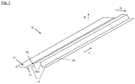
- FIG figure 1 shows a component segment 10 according to a preferred embodiment of the invention, with which a reinforced planar component 14 is produced, as in FIG figure 2 shown as an embodiment.
- a plurality of component segments 10 are provided in order to produce the reinforced planar component 14 therefrom.
- Each component segment 10 is designed as a profile that extends in a longitudinal direction L and is made of a fiber-reinforced thermoplastic material.
- the component segment 10 comprises a flat first profile area 11 and a second profile area 12 shaped as a stiffening profile.
- the two profile areas 11, 12 of the component segment 10 extend side by side in the longitudinal direction L of the component segment 10.
- the provided component segments 10 are joined together laterally in order to form the component 14 to be produced, as shown in figure 2 is shown.
- the first profile area 11 of a component segment 10 and the second profile area 12 of the adjacent component segment 10 overlap in each case.
- the component segments 10 are then welded in the overlapping profile areas in order to form the component 14 .
- the first profile areas 11 of the joined component segments 10 together form a skin area 15 of the manufactured component 14.
- the second profile areas 12 of the joined component segments 14 together form a stiffening structure 16 of the manufactured component 14.
- a connecting section 17 of the second profile area 12 for planar welding to the first profile area 11 of an adjacent component segment 10 is formed higher than the first profile area 11 . This has the effect that when two component segments 10 are joined together, their first profile regions 11 lie in one plane.
- the connecting section 17 forms a step or an offset 31 relative to the first profile area 11 , which runs in the thickness direction D of the component segment 10 and essentially corresponds to the thickness of the flat, first profile area 11 .
- the component segments 10 that have been joined together and welded to one another lie next to one another and adjoin one another in one plane, as a result of which they form the skin area 15 of the component 24 produced.
- the welding of the component segments 10 takes place in the planar connecting sections 17, which are formed in the second profile area 12 of each component segment 10 and are aligned parallel to the respectively adjoining, planar first profile areas 11 when the component segments 10 are in the assembled state.
- a weld seam 18 is created on the contact surfaces between the connecting sections 17 and the flat first profile areas 11 .
- thermoplastic material For welding, heat is applied or generated to bring the thermoplastic material above its melting point in the contact areas, which can be done, for example, by means of ultrasound, infrared radiation, laser beams or other methods suitable for this purpose.
- the welding of the joined component segments 10 can also be carried out in an autoclave, for example take place.
- the heat for producing the weld seams is preferably introduced with the aid of a robot in a targeted manner into the contact areas of the connecting sections 17, with the robot moving along the connecting sections 17 or over them.
- Each component segment 10 includes a stiffening section 19 which gives the component segment the required rigidity.
- the stiffening section 19 is designed as an elevation compared to the connecting sections 17 in the second profile area 12 , which border on both sides of the stiffening section 19 in the transverse direction Q of the component segment 10 .
- each individual component segment 10 forms an omega stiffening profile with sloping flanks 19a of the stiffening section 19 through its second profile area 12. That is, an omega panel is formed.
- closed omega reinforcement profiles or hollow profiles which are formed side by side and parallel to one another on the skin 15 which is formed by the flat, first profile areas 11
- stiffening profiles are formed, in particular Z, C or else D stiffening profiles.
- the component segments 10 are preferably made from a high-performance thermoplastic as the matrix material, in which reinforcing fibers, preferably made of carbon, are embedded.
- the thermoplastic material is selected in particular from the group of high-temperature thermoplastic polymers, high-performance plastics, semi-crystalline high-performance plastics, polyaryletherketones (PAEK) such as polyetherketoneketone (PEKK), polyetherketone (PEK), polyetheretherketone (PEEK), polyetheretherketoneketone (PEEKK) and polyetherketone-etherketoneketone (PEKEKK) .
- PEEK and PEKK are particularly preferred.
- the melting point of the high-performance thermoplastics used here is above 300.degree. C., preferably above 350.degree.
- the component segments 10 are produced, for example, by pultrusion or roll forming. Production is advantageously carried out continuously, with a profile being produced continuously from the fiber-reinforced thermoplastic material, for example in a press, and then being cut into component segments of the required length. The profile or its segments can be trimmed and/or reshaped as required.
- the component segments 10 In order to manufacture the component segments 10, it is also possible to produce flat sheet metal from the thermoplastic material as preliminary products, which are then formed in a press in order to obtain the profile for the component segments. Depending on the requirements, both the profile from which the component segments 10 are formed and the individual component segments 10 can be cut to size and/or shaped by heating and pressing. During forming, the component segments 10 are curved, for example in the transverse direction Q, before or after the welding, depending on the application. In this case, the skin panel 15 forms a curved surface
- the component formed from the compressed component segments has a high level of rigidity and can also be cut to size as required and, for example, melted and pressed in the edge areas.
- the method can be used to produce both flat panels and curved or arched surface components as reinforced aircraft components.
- the component produced in this way is, for example, a shell element, a cover element, a flat plate element and/or a curved plate element.
- the second profile area 12 of the component segment 20, which laterally adjoins the first profile area 11 is Z-shaped and thus forms a Z-reinforcing element.
- the connecting section 17 for planar welding to the first profile area 11 of an adjacent component segment 20 is, as in the case of FIG figure 1 shown component segment 10, increased compared to the first profile area 11 and also forms the offset 31.
- the second profile area 12 only partially overlaps the first profile area 11 of the adjacent component segment 20.
- the stiffening profile 19 formed by the second profile area 12 forms an elevation relative to the connecting section 17 and the first profile area 11, but with only one flank 19a which runs perpendicular to the profile base, which is formed by the connecting section 17. In this way, the second profile area 12 forms a Z stiffening profile. In the welded state of the component segments 20 that have been joined together, this results in a number of Z-shaped stiffening profiles or sections 19 which are formed next to one another and parallel to one another on the skin 15, which are formed by the adjacent first profile sections 11 of the welded component segments 24 and together form the stiffening structure 16.
- thermoplastic material can also be produced as preliminary products for the production of the component segments 20, which are then formed in a press in order to obtain the profile for the component segments.
- both the profile from which the component segments 20 are formed and the individual component segments 20 can be cut to size and/or shaped by heating and pressing.
- the component segments 20 are curved in the transverse direction Q, for example, before or after the welding, depending on the application.
- the skin panel 15 forms a curved surface
- figure 5 shows an aircraft 100, whose fuselage 101, wings 102, vertical stabilizer 103 and horizontal stabilizer 104 as well as other elements such as landing flaps are produced using the method according to the invention and the component segment 10, 20 according to the invention.
Landscapes
- Engineering & Computer Science (AREA)
- Mechanical Engineering (AREA)
- Aviation & Aerospace Engineering (AREA)
- Moulding By Coating Moulds (AREA)
Abstract
Description
- Die Erfindung betrifft ein Verfahren zur Herstellung eines versteiften flächigen Bauteils für Luftfahrzeuge, wobei das herzustellende Bauteil ein Hautfeld und eine Versteifungsstruktur umfasst. Weiterhin betrifft die Erfindung ein Bauteilsegment zur Herstellung eines versteiften flächigen Bauteils für Luftfahrzeuge, und ein Luftfahrzeug.
- Mit dem Verfahren werden insbesondere Bauteile wie zum Beispiel versteifte thermoplastische Platten oder Paneele, Schalenbauteile, Abdeckungen und Ähnliches hergestellt.
- Bauteile für Luftfahrzeuge müssen über eine hohe Festigkeit und Steifigkeit verfügen und dabei ein möglichst geringes Gewicht aufweisen. Als Materialien eignen sich daher insbesondere faserverstärkte Thermoplaste. Die Bauteile werden zum Beispiel als Schalenelemente, Paneele oder Platten, Abdeckungen, usw. ausgebildet, die zumeist an einer Seite durch Versteifungselemente verstärkt werden, um dadurch den oft dünnwandigen, flächigen Bauteilen die erforderliche Steifigkeit oder Festigkeit zu verleihen. Im Flugzeugbau werden zum Beispiel der Rumpf, Rumpfschalen, Höhenleitwerke, Seitenleitwerke, Tragflächen, usw. mit derartigen Bauteilen hergestellt.
-
EP 3 733 391 A1 beschreibt zum Beispiel ein Verfahren zum Herstellen eines versteiften flächigen Bauteils aus Polymermaterial. Dabei werden Versteifungshohlprofile wie Stringer und eine Außenhaut aus thermoplastischem Verbundwerkstoff hergestellt. Die Stringer werden anschließend mit der Außenhaut in Kontakt gebracht und der thermoplastische Verbundwerkstoff wird unter Einwirkung von Hitze und Druck bei den Kontaktflächen zwischen der Außenhaut und den Stringern geschmolzen. -
DE 10 2018 215 356 A1 zeigt ein Verfahren zum Herstellen eines Rumpfbauteils für ein Luftfahrzeug. Dabei werden auf einer Oberfläche eines sich flächig erstreckenden Schalenteils aus einem Faserverbundmaterial Versteifungsprofile aus einer Vielzahl von übereinander liegenden Schichten aufgebaut. Die Schichten werden jeweils durch Auftragen von Filamenten, die jeweils ein in ein Thermoplastmaterial eingebettetes Faserbündel aufweisen, ausgebildet. - Insbesondere bei Flugzeugen sind die versteiften flächigen Bauteile oft großformatig. Dadurch kann der Aufwand des Verbindens mehrerer Bauteile verringert werden. Jedoch erfordern die großen Bauteile bei der Herstellung sehr große formgebende Werkzeuge, Pressen und Autoklaven, die hohe Kosten verursachen.
- Die Erfindung hat sich zur Aufgabe gestellt, den Aufwand bei der Herstellung von Bauteilen zu verringern und die Kosten zu reduzieren.
- Die Aufgabe wird gelöst durch das Verfahren nach Patentanspruch 1.
- Vorteilhafte Ausgestaltungen sind Gegenstand der Unteransprüche.
- Gemäß einem ersten Aspekt schafft die Erfindung ein Verfahren zur Herstellung eines versteiften flächigen Bauteils für Luftfahrzeuge, wobei das herzustellende Bauteil ein Hautfeld und eine Versteifungsstruktur umfasst, umfassend die Schritte:
- a) Bereitstellen mehrerer Bauteilsegmente, die jeweils als ein längliches Profil aus einem faserverstärkten thermoplastischen Material ausgebildet sind, wobei jedes Bauteilsegment einen flächig geformten ersten Profilbereich und einen als Versteifungsprofil geformten zweiten Profilbereich umfasst;
- b) Aneinanderfügen der Bauteilsegmente, wobei jeweils der erste Profilbereich eines Bauteilsegments mit dem zweiten Profilbereich eines benachbarten Bauteilsegments zumindest teilweise überlappt; und
- c) Verschweißen der Bauteilsegmente in den überlappenden Profilbereichen, um das Bauteil zu bilden, wobei die ersten Profilbereiche der Bauteilsegmente das Hautfeld des Bauteils bilden, und die zweiten Profilbereiche der Bauteilsegmente die Versteifungsstruktur des Bauteils bilden.
- Die Erfindung ermöglicht eine schnelle Herstellung auch sehr großer, flächiger versteifter Bauteile für Luftfahrzeuge aus faserverstärktem thermoplastischem Material, ohne dass entsprechend große Werkzeuge wie Pressen, Formwerkzeuge und Autoklaven erforderlich sind. Durch die Fertigung aus einem oder mehreren Profilen können Arbeitsschritte schneller und mit höherem Automatisierungsgrad durchgeführt werden.
- Das Pressen von kompletten integralen Komponenten oder das nachfolgende Schweißen von Versteifungselementen auf die Haut bzw. das Hautfeld entfällt. Dadurch, dass Haut und Versteifungselemente zusammen als ein Teil in jedem Bauteilsegment geformt und bereitgestellt werden, müssen diese nicht mehr separat voneinander hergestellt oder ausgebildet werden. Insbesondere entfällt auch ein nachträgliches Ausbilden von Versteifungselementen auf der Haut.
- Bevorzugt erstrecken sich der erste Profilbereich und der zweite Profilbereich nebeneinander in Längsrichtung des Bauteilsegments.
- Vorteilhafterweise werden der erste Profilbereich und der zweite Profilbereich seitlich aneinandergefügt.
- Bevorzugt umfassen die zweiten Profilbereiche der Bauteilsegmente jeweils mindestens einen flächig ausgebildeten Verbindungsabschnitt zum flächigen Verschweißen und einen in Querrichtung des jeweiligen Bauteilsegments angrenzenden Versteifungsabschnitt, der höher oder tiefer liegt als der Verbindungsabschnitt.
- Vorteilhaft werden die zweiten Profilbereiche der Bauteilsegmente als Omega-, Z-, C-, und/oder T-Versteifungsprofil ausgebildet.
- Beispielsweise bilden im hergestellten Bauteil die zweiten Profilbereiche zusammen mit den ersten Profilbereichen Hohlprofile, Omega-Profile, geschlossene Omega-Profile, Z-Profile, T-Profile und/oder C-Profile.
- Bevorzugt werden die Bauteilsegmente durch Strangziehen bzw. Pultrusion und/oder durch Rollformen hergestellt.
- Vorteilhaft werden mehrere Bauteilsegmente aus einem einzigen Profil geschnitten und anschließend seitlich aneinandergefügt.
- Bevorzugt werden die Bauteilsegmente zugeschnitten und/oder umgeformt.
- Beispielsweise können die Bauteilsegmente einzeln vor und/oder gemeinsam nach dem Verschweißen umgeformt werden. Beispielsweise werden die Bauteilsegmente und/oder das Bauteil gekrümmt, wobei es insbesondere auch zylindrisch, als eine Röhre oder als ein Segment einer Röhre bzw. eines Zylinders geformt werden kann.
- Durch das Verfahren wird insbesondere ein durch Stringer und/oder Spanten verstärktes Schalenelement hergestellt. Insbesondere wird als Bauteil ein Rumpfbauteil wie z.B. ein Rumpfsegment oder ein Rumpf, ein Flügelbauteil, ein Seitenleitwerk, ein Höhenleitwerk, eine Landeklappe, oder jeweils zumindest ein Teil davon.
- Vorteilhaft werden die Bauteilsegmente aus einem Hochleistungsthermoplast als Matrixmaterial gefertigt.
- Insbesondere wird zur Bildung des faserverstärkten thermoplastischen Materials ein Matrixmaterial verwendet, das ausgewählt wird aus der Gruppe Hochtemperatur-thermoplastische Polymere, Hochleistungskunststoffe, teilkristalline Hochleistungskunststoffe, Polyaryletherketone (PAEK) wie Polyetherketonketon (PEKK), Polyetherketon (PEK), Polyetheretherketon (PEEK), Polyetheretherketonketon (PEEKK) und Polyetherketon-etherketonketon (PEKEKK).
- Bevorzugt umfasst das thermoplastische Material synthetische Fasern, besonders bevorzugt Kohlenstofffasern, die in das Matrixmaterial eingebettet sind.
- Bevorzugt wird als Bauteil ein Schalenelement, ein Abdeckelement, ein ebenes Plattenelement, und/oder ein gekrümmtes Plattenelement hergestellt.
- Vorteilhafterweise werden die Bauteilsegmente derart geformt, dass der zweite Profilbereich in Dickenrichtung gegenüber dem ersten Profilbereich versetzt ist. Der Versatz wird insbesondere senkrecht zur Flächenebene des ersten Profilbereichs ausgebildet und ist vorteilhafterweise so bemessen, dass beim Aneinanderfügen der Bauteilsegmente deren erste Profilbereiche eine Ebene bilden, auf der die zweiten Profilbereiche der aneinandergefügten Bauteilsegmente ausgebildet sind.
- Vorzugsweise umfassen die Profilbereiche der Bauteilsegmente flächig ausgebildete Verbindungsbereiche, die mit den Hautbereichen jeweils benachbarter Bauteilsegmente flächig verschweißt werden und dabei insbesondere parallel zu diesen ausgerichtet sind.
- Gemäß einem zweiten Aspekt schafft die Erfindung ein Bauteilsegment zur Herstellung eines versteiften flächigen Bauteils für Luftfahrzeuge, wobei das Bauteilsegment als ein Profil aus einem faserverstärkten thermoplastischen Material ausgebildet ist, und einen flächig geformten ersten Profilbereich und einen als Versteifungsprofil geformten zweiten Profilbereich umfasst, wobei das Bauteilsegment derart gestaltet ist, dass beim seitlichen Anfügen eines weiteren Bauteilsegments der erste Profilbereich des einen Bauteilsegments mit dem zweiten Profilbereich des anderen Bauteilsegments zumindest teilweise überlappt, um durch Verschweißen der Bauteilsegmente in den überlappenden Profilbereichen das versteifte flächige Bauteil zu bilden, wobei die ersten Profilbereiche der Bauteilsegmente ein Hautfeld des Bauteils bilden, und die zweiten Profilbereiche der Bauteilsegmente eine Versteifungsstruktur des Bauteils bilden.
- Vorzugsweise erstrecken sich der erste und der zweite Profilbereich nebeneinander in Längsrichtung des Bauteilsegments.
- Bevorzugt ist der zweite Profilbereich gegenüber dem ersten Profilbereich derart in der Höhe versetzt, dass beim Überlappen der Bauteilsegmente deren flächig geformte erste Profilbereiche eine Ebene bilden, auf der die zweiten Profilbereiche der aneinandergefügten Bauteilsegmente ausgebildet sind.
- Vorteilhaft ist der zweite Profilbereich als Omega-, Z-, C-, und/oder T-Versteifungsprofil ausgebildet.
- Insbesondere bildet jedes Bauteilsegment sowohl das Hautfeld als auch die Versteifungsstruktur des hergestellten Bauteils.
- Bevorzugt ist das Bauteilsegment aus einem faserverstärktem Hochleistungsthermoplast gefertigt.
- Vorzugsweise werden zur Verstärkung des thermoplastischen Materials Kohlenstofffasern verwendet.
- Zum Beispiel ist das Bauteilsegment gekrümmt, vorzugsweise in seiner Querrichtung, sodass durch Verschweißen mehrerer Bauteilsegmente ein gekrümmtes Bauteil entsteht.
- Bevorzugt ist das Bauteilsegment zur Verwendung in dem erfindungsgemäßen Verfahren ausgestaltet.
- Vorteilhaft weist das Bauteilsegment die Merkmale der in dem erfindungsgemäßen Verfahren verwendeten Bauteilsegmente auf.
- Gemäß einem dritten Aspekt schafft die Erfindung ein Luftfahrzeug, das ein Bauteil umfasst, das mit dem erfindungsgemäßen Verfahren und/oder mit dem erfindungsgemäßen Bauteilsegment hergestellt ist.
- Das Bauteil ist insbesondere ein durch Stringer und/oder Spanten verstärktes Schalenelement. Beispielsweis kann das Bauteil auch gekrümmt sein, wobei es insbesondere auch zylindrisch, als eine Röhre oder als ein Segment einer Röhre geformt sein kann. Beispielsweise ist das hergestellte Bauteil ein Rumpfbauteil wie z.B. ein Rumpfsegment oder ein Rumpf, ein Flügelbauteil, ein Seitenleitwerk, ein Höhenleitwerk, eine Landeklappe, oder jeweils zumindest ein Teil davon.
- Vorteile, Details, und Merkmale, die im Zusammenhang mit dem Verfahren zur Herstellung eines versteiften flächigen Bauteils beschrieben sind, gelten jeweils wechselseitig auch für die anderen Aspekte der Erfindung.
- Ein Ausführungsbeispiel wird im Folgenden anhand der beigefügten Zeichnungen näher erläutert. Darin zeigen:
- Fig. 1
- ein Bauteilsegment gemäß einer bevorzugten Ausführungsform der Erfindung, das in einem bevorzugten Ausführungsbeispiel des erfindungsgemäßen Verfahrens verwendet wird, in einer räumlichen schematischen Darstellung;
- Fig. 2
- mehrere aneinandergefügte Bauteilsegmente, wie sie in
Fig. 1 dargestellt sind, in einer schematischen Querschnittsdarstellung; - Fig. 3
- ein Bauteilsegment gemäß einer anderen bevorzugten Ausführungsform der Erfindung, das in einem bevorzugten Ausführungsbeispiel des erfindungsgemäßen Verfahrens verwendet wird, in einer räumlichen schematischen Darstellung;
- Fig. 4
- mehrere aneinandergefügte Bauteilsegmente, wie sie in
Fig. 3 dargestellt sind, in einer schematischen Querschnittsdarstellung; und - Fig. 5
- ein Luftfahrzeug, das Bauteile umfasst, die mit dem erfindungsgemäßen Verfahren oder mit dem erfindungsgemäßen Bauteilsegment hergestellt sind, in einer schematischen Ansicht von oben.
- In den Figuren sind gleiche oder einander entsprechende Elemente jeweils mit den gleichen Bezugszeichen bezeichnet und werden daher nicht erneut beschrieben, sofern es nicht zweckmäßig erscheint. Die in der gesamten Beschreibung enthaltenen Offenbarungen sind sinngemäß auf gleiche Teile mit gleichen Bezugszeichen bzw. gleichen Bauteilbezeichnungen übertragbar. Auch sind die in der Beschreibung gewählten Lageangaben, wie z.B. oben, unten, seitlich usw. auf die unmittelbar beschriebene sowie dargestellte Figur bezogen und sind bei einer Lageänderung sinngemäß auf die neue Lage zu übertragen. Weiterhin können auch Einzelmerkmale oder Merkmalskombinationen aus den gezeigten und beschriebenen unterschiedlichen Ausführungsbeispielen für sich eigenständige, erfinderische oder erfindungsgemäße Lösungen darstellen.
-
Figur 1 zeigt ein Bauteilsegment 10 gemäß einer bevorzugten Ausführungsform der Erfindung, mit dem ein versteiftes flächiges Bauteil 14 hergestellt wird, wie inFigur 2 als ein Ausführungsbeispiel gezeigt. In dem hier beschriebenen ersten Ausführungsbeispiel des erfindungsgemäßen Verfahrens werden mehrere Bauteilsegmente 10 bereitgestellt, um daraus das versteifte flächige Bauteil 14 herzustellen. Jedes Bauteilsegment 10 ist als ein Profil ausgebildet, das sich in einer Längsrichtung L erstreckt und aus einem faserverstärkten thermoplastischen Material gefertigt ist. - Das Bauteilsegment 10 umfasst einen flächig geformten ersten Profilbereich 11 und einen als Versteifungsprofil geformten zweiten Profilbereich 12. Die beiden Profilbereiche 11, 12 des Bauteilsegments 10 erstrecken sich nebeneinander in der Längsrichtung L des Bauteilsegments 10.
- In einem nächsten Schritt des Herstellungsverfahrens werden die bereitgestellten Bauteilsegmente 10 seitlich aneinandergefügt, um das herzustellende Bauteil 14 zu bilden, wie es in
Figur 2 gezeigt ist. Dabei überlappen sich jeweils der erste Profilbereich 11 eines Bauteilsegments 10 und der zweite Profilbereich 12 des benachbarten Bauteilsegments 10. - Anschließend werden die Bauteilsegmente 10 in den überlappenden Profilbereichen verschweißt, um das Bauteil 14 zu bilden. Dabei bilden die ersten Profilbereiche 11 der aneinandergefügten Bauteilsegmente 10 gemeinsam ein Hautfeld 15 des hergestellten Bauteils 14. Die zweiten Profilbereiche 12 der aneinandergefügten Bauteilsegmente 14 bilden gemeinsam eine Versteifungsstruktur 16 des hergestellten Bauteils 14.
- Ein Verbindungsabschnitt 17 des zweiten Profilbereichs 12 zum flächigen Verschweißen mit dem ersten Profilbereich 11 eines benachbarten Bauteilsegments 10 ist erhöht gegenüber dem ersten Profilbereich 11 ausgebildet. Dadurch wird bewirkt, dass beim Zusammenfügen zweier Bauteilsegmente 10 deren erste Profilbereiche 11 in einer Ebene liegen.
- In dem Bauteilsegment 10 bildet der Verbindungsabschnitt 17 gegenüber dem ersten Profilbereich 11 eine Stufe bzw. einen Versatz 31, welcher in Dickenrichtung D des Bauteilsegments 10 verläuft und im Wesentlichen der Dicke des flächigen, ersten Profilbereich 11 entspricht. Dadurch liegen die aneinandergefügten und miteinander verschweißten Bauteilsegmente 10 nebeneinander und grenzen in einer Ebene aneinander, wodurch sie das Hautfeld 15 des hergestellten Bauteils 24 bilden.
- Das Verschweißen der Bauteilsegmente 10 erfolgt in den flächig ausgebildeten Verbindungsabschnitten 17, die im zweiten Profilbereich 12 jedes Bauteilsegments 10 ausgebildet sind und im zusammengefügten Zustand der Bauteilesegmente 10 parallel zu den jeweils angrenzenden, flächigen ersten Profilbereichen 11 ausgerichtet sind. Beim Verschweißen wird jeweils eine Schweißnaht 18 an den Kontaktflächen zwischen den Verbindungsabschnitten 17 und den flächigen ersten Profilbereichen 11 geschaffen.
- Zum Verschweißen wird Wärme zugeführt bzw. erzeugt, um das thermoplastische Material in den Kontaktbereichen über seinen Schmelzpunkt zu bringen, was zum Beispiel mit Ultraschall, Infrarotstrahlung, Laserstrahlen oder anderen für diesen Zweck geeigneten Verfahren erfolgen kann. Auch kann das Verschweißen der aneinandergefügten Bauteilsegmente 10 zum Beispiel in einem Autoklaven erfolgen. Vorzugsweise wird die Wärme zum Erzeugen der Schweißnähte mithilfe eines Roboters gezielt in die Kontaktbereiche der Verbindungsabschnitte 17 eingebracht, wobei sich der Roboter entlang der Verbindungsabschnitte 17 bzw. über diesen bewegt.
- Jedes Bauteilsegment 10 umfasst einen Versteifungsabschnitt 19, der dem Bauteilsegment die erforderliche Steifigkeit verleiht. Zu diesem Zweck ist der Versteifungsabschnitt 19 als eine Erhöhung gegenüber den Verbindungsabschnitten 17 im zweiten Profilbereich 12 ausgebildet, die an beiden Seiten des Versteifungsabschnitts 19 in Querrichtung Q des Bauteilsegments 10 an diesen angrenzen.
- Auf diese Weise bildet jedes einzelne Bauteilsegmente 10 durch seinen zweiten Profilbereich 12 ein Omega-Versteifungsprofil mit schräg verlaufenden Flanken 19a des Versteifungsabschnitts 19. Beim Verschweißen entstehen pro Bauteilsegment 10 zwei Schweißnähte 18, d. h., es wird ein Omega-Paneel gebildet. Im verschweißten Zustand der aneinandergefügten Bauteilsegmente 10 ergibt sich eine Anzahl von geschlossenen Omega-Versteifungsprofilen bzw. Hohlprofilen, die nebeneinander und parallel zueinander auf der Haut 15 ausgebildet sind, die durch die flachen, ersten Profilbereiche 11 gebildet wird
- In anderen Ausführungsformen der Erfindung, von denen eine als Beispiel weiter unten noch im Detail beschrieben wird, werden anders geformte Versteifungsprofile ausgebildet, insbesondere Z-, C- oder auch D-Versteifungsprofile.
- Bevorzugt sind die Bauteilsegmente 10 aus einem Hochleistungsthermoplast als Matrixmaterial gefertigt, in dem Verstärkungsfasern vorzugsweise aus Kohlenstoff eingebettet sind. Das thermoplastische Material ist insbesondere ausgewählt aus der Gruppe Hochtemperatur-thermoplastische Polymere, Hochleistungskunststoffe, teilkristalline Hochleistungskunststoffe, Polyaryletherketone (PAEK) wie Polyetherketonketon (PEKK), Polyetherketon (PEK), Polyetheretherketon (PEEK), Polyetheretherketonketon (PEEKK) und Polyetherketon-etherketonketon (PEKEKK). Besonders bevorzug sind dabei PEEK und PEKK.
- Der Schmelzpunkt der hier verwendeten Hochleistungsthermoplaste liegt bei über 300 °C, bevorzugt über 350 °C.
- Die Bauteilsegmente 10 werden zum Beispiel durch Strangziehen oder Rollformen hergestellt. Vorteilhaft erfolgt die Herstellung kontinuierlich, wobei ein Profil aus dem faserverstärkten thermoplastischen Material zum Beispiel in einer Presse kontinuierlich erzeugt und anschließend in Bauteilsegmente mit der erforderlichen Länge geschnitten wird. Das Profil oder dessen Segmente können je nach Erfordernis zurechtgeschnitten und/oder umgeformt werden.
- Zur Fertigung der Bauteilsegmente 10 können auch flache Bleche aus dem thermoplastischen Material als Vorerzeugnisse hergestellt werden, die anschließend in einer Presse umgeformt werden, um das Profil für die Bauteilsegmente zu erhalten. Je nach Erfordernis können sowohl das Profil, aus dem die Bauteilsegmente 10 gebildet werden, als auch die einzelnen Bauteilsegmente 10 zurechtgeschnitten und/oder durch Erhitzen und Pressen umgeformt werden. Beim Umformen werden die Bauteilsegmente 10 vor oder nach dem Verschweißen je nach Anwendungsfall zum Beispiel in der Querrichtung Q gekrümmt. In diesem Fall bildet das Hautfeld 15 eine gekrümmte Fläche
- Das aus den zusammengepressten Bauteilsegmenten gebildete Bauteil weist eine hohe Steifigkeit auf und kann je nach Erfordernis ebenfalls zugeschnitten und zum Beispiel in den Randbereichen aufgeschmolzen und verpresst werden.
- Mit dem Verfahren können sowohl ebene Platten als auch gekrümmte oder gewölbte Flächenbauteile als versteifte Luftfahrzeugbauteile hergestellt werden. Das auf diese Weise hergestellte Bauteil ist zum Beispiel ein Schalenelement, ein Abdeckelement, ein ebenes Plattenelement und/oder ein gekrümmtes Plattenelement.
- Anhand der
Figuren 3 und4 wird nachfolgend ein weiteres bevorzugtes Ausführungsbeispiel des Herstellungsverfahrens beschrieben, mit einem Bauteilsegment 20 bzw. einem hergestellten Bauteil 24 gemäß einer weiteren bevorzugten Ausführungsform der Erfindung. - Im Unterschied zu dem oben beschriebenen Ausführungsbeispiel ist in dieser Ausführungsform der zweiten Profilbereich 12 des Bauteilsegments 20, der seitlich an den ersten Profilbereich 11 angrenzt, Z-förmig und bildet somit ein Z-Versteifungselement.
- Der Verbindungsabschnitt 17 zum flächigen Verschweißen mit dem ersten Profilbereich 11 eines benachbarten Bauteilsegments 20 ist, ebenso wie bei dem in
Figur 1 gezeigten Bauteilsegment 10, erhöht gegenüber dem ersten Profilbereich 11 und bildet ebenfalls den Versatz 31. - Beim Zusammenfügen der Bauteilsegmente 20, wie es in
Figur 4 gezeigt ist, überlappt der zweiten Profilbereich 12 nur teilweise den ersten Profilbereich 11 des benachbarten Bauteilsegments 20. - Das durch den zweiten Profilbereich 12 gebildete Versteifungsprofil 19 bildet relativ zum Verbindungsabschnitt 17 und zum ersten Profilbereich 11 eine Erhöhung, jedoch mit nur einer Flanke 19a, die senkrecht zur Profilbasis verläuft, welche durch den Verbindungsabschnitt 17 gebildet wird. Auf diese Weise formt der zweite Profilbereich 12 ein Z-Versteifungsprofil. Im verschweißten Zustand der aneinandergefügten Bauteilsegmente 20 ergibt sich somit eine Anzahl von Z-förmigen Versteifungsprofilen bzw. -abschnitten 19, die nebeneinander und parallel zueinander auf der Haut 15 ausgebildet sind, die durch die nebeneinanderliegenden ersten Profilabschnitte 11 der verschweißten Bauteilsegmente 24 gebildet sind und gemeinsam die Versteifungsstruktur 16 bilden.
- Die übrigen Merkmale des Bauteilsegments 20 und des damit hergestellten Bauteils 24 entsprechen den Merkmalen, die unter Bezugnahme auf die
Figuren 1 und2 beschrieben sind und auf die hier Bezug genommen wird. Ebenso entspricht das Verfahren zum Herstellen des versteiften flächigen Bauteils 24 in seinen weiteren Details dem oben bereits beschriebenen Verfahren. - Insbesondere können, wie oben beschrieben, auch zur Fertigung der Bauteilsegmente 20 flache Bleche aus dem thermoplastischen Material als Vorerzeugnisse hergestellt werden, die anschließend in einer Presse umgeformt werden, um das Profil für die Bauteilsegmente zu erhalten. Je nach Erfordernis können sowohl das Profil, aus dem die Bauteilsegmente 20 gebildet werden, als auch die einzelnen Bauteilsegmente 20 zurechtgeschnitten und/oder durch Erhitzen und Pressen umgeformt werden. Beim Umformen werden die Bauteilsegmente 20 vor oder nach dem Verschweißen je nach Anwendungsfall zum Beispiel in der Querrichtung Q gekrümmt. In diesem Fall bildet das Hautfeld 15 eine gekrümmte Fläche
-
Figur 5 zeigt ein Luftfahrzeug 100, dessen Rumpf 101, Flügel 102, Seitenleitwerk 103 und Höhenleitwerk 104 sowie weitere Elemente wie etwa Landeklappen mit dem erfindungsgemäßen Verfahren und dem erfindungsgemäßen Bauteilsegment 10, 20 hergestellt sind. -
- 10
- Bauteilsegment
- 11
- erster Profilbereich
- 12
- zweiter Profilbereich
- 14
- versteiftes flächiges Bauteil
- 15
- Hautfeld, Haut
- 16
- Versteifungsstruktur
- 17
- Verbindungsabschnitt
- 18
- Schweißnaht
- 19
- Versteifungsabschnitt
- 19a
- Flanke(n)
- 20
- Bauteilsegment
- 24
- versteiftes flächiges Bauteil
- 31
- Versatz
- D
- Dickenrichtung
- L
- Längsrichtung
- Q
- Querrichtung
Claims (15)
- Verfahren zur Herstellung eines versteiften flächigen Bauteils (14, 24) für Luftfahrzeuge, wobei das herzustellende Bauteil (14, 24) ein Hautfeld (15) und eine Versteifungsstruktur (16) umfasst, umfassend die Schritte:d) Bereitstellen mehrerer Bauteilsegmente (10, 20), die jeweils als ein längliches Profil aus einem faserverstärkten thermoplastischen Material ausgebildet sind, wobei jedes Bauteilsegment (10, 20) einen flächig geformten ersten Profilbereich (11) und einen als Versteifungsprofil geformten zweiten Profilbereich (12) umfasst;e) Aneinanderfügen der Bauteilsegmente (10, 20), wobei jeweils der erste Profilbereich (11) eines Bauteilsegments (10, 20) mit dem zweiten Profilbereich eines benachbarten Bauteilsegments (10, 20) zumindest teilweise überlappt; undf) Verschweißen der Bauteilsegmente (10, 20) in den überlappenden Profilbereichen, um das Bauteil (14, 24) zu bilden, wobei die ersten Profilbereiche (11) der Bauteilsegmente (10, 20) das Hautfeld (15) des Bauteils (14, 24) bilden, und die zweiten Profilbereiche (12) der Bauteilsegmente (10, 20) die Versteifungsstruktur (16) des Bauteils (14, 24) bilden.
- Verfahren nach Anspruch 1, dadurch gekennzeichnet, dass sich der erste Profilbereich (11) und der zweite Profilbereich (12) nebeneinander in Längsrichtung (L) des Bauteilsegments (10, 20) erstrecken und seitlich aneinandergefügt werden.
- Verfahren nach Anspruch 1 oder 2, dadurch gekennzeichnet, dass die zweiten Profilbereiche (12) der Bauteilsegmente (10, 20) jeweils mindestens einen flächig ausgebildeten Verbindungsabschnitt (17) zum flächigen Verschweißen und einen in Querrichtung (Q) des jeweiligen Bauteilsegments (10, 20) angrenzenden Versteifungsabschnitt (19) umfassen, der höher oder tiefer liegt als der Verbindungsabschnitt (17).
- Verfahren nach einem der vorhergehenden Ansprüche, dadurch gekennzeichnet, dass die zweiten Profilbereiche (12) der Bauteilsegmente (10, 20) als Omega-, Z-, C-, und/oder T-Versteifungsprofil ausgebildet werden.
- Verfahren nach einem der vorhergehenden Ansprüche, dadurch gekennzeichnet, dass die Bauteilsegmente (10, 20) durch Strangziehen und/oder Rollformen hergestellt werden.
- Verfahren nach einem der vorhergehenden Ansprüche, dadurch gekennzeichnet, dass mehrere Bauteilsegmente (10, 20) aus einem einzigen Profil geschnitten werden, und anschließend seitlich aneinandergefügt werden.
- Verfahren nach einem der vorhergehenden Ansprüche, dadurch gekennzeichnet, dass die Bauteilsegmente (10, 20) zugeschnitten und/oder umgeformt werden.
- Verfahren nach einem der vorhergehenden Ansprüche, dadurch gekennzeichnet, dass die Bauteilsegmente (10, 20) aus einem Hochleistungsthermoplast als Matrixmaterial gefertigt werden.
- Verfahren nach einem der vorhergehenden Ansprüche, dadurch gekennzeichnet, dass zur Bildung des faserverstärkten thermoplastischen Materials ein Matrixmaterial verwendet wird, das ausgewählt wird aus der Gruppe Hochtemperatur-thermoplastische Polymere, Hochleistungskunststoffe, teilkristalline Hochleistungskunststoffe, Polyaryletherketone wie Polyetherketonketon, Polyetherketon, Polyetheretherketon, Polyetheretherketonketon und Polyetherketon-etherketonketon.
- Verfahren nach einem der vorhergehenden Ansprüche, dadurch gekennzeichnet, dass als Bauteil (14, 24) ein Schalenelement, ein Abdeckelement, ein ebenes Plattenelement, und/oder ein gekrümmtes Plattenelement hergestellt wird.
- Bauteilsegment zur Herstellung eines versteiften flächigen Bauteils für Luftfahrzeuge, wobei das Bauteilsegment (10, 20) als ein Profil aus einem faserverstärkten thermoplastischen Material ausgebildet ist; und
einen flächig geformten ersten Profilbereich (11) und einen als Versteifungsprofil geformten zweiten Profilbereich umfasst;
wobei das Bauteilsegment (10, 20) derart gestaltet ist, dass beim seitlichen Anfügen eines weiteren Bauteilsegments (10, 20) der erste Profilbereich (11) des einen Bauteilsegments (10, 20) mit dem zweiten Profilbereich (12) des anderen Bauteilsegments (10, 20) zumindest teilweise überlappt, um durch Verschweißen der Bauteilsegmente (10, 20) in den überlappenden Profilbereichen das versteifte flächige Bauteil (14, 24) zu bilden,
wobei die ersten Profilbereiche (11) der Bauteilsegmente (10, 20) ein Hautfeld (15) des Bauteils (14, 24) bilden, und die zweiten Profilbereiche (12) der Bauteilsegmente (10, 20) eine Versteifungsstruktur (16) des Bauteils (14, 24) bilden. - Bauteilsegment nach Anspruch 11, dadurch gekennzeichnet, dass der zweite Profilbereich (12) gegenüber dem ersten Profilbereich (11) derart in der Höhe versetzt ist, dass beim Überlappen der Bauteilsegmente (10, 20) deren flächig geformte erste Profilbereiche (11) eine Ebene bilden, auf der die zweiten Profilbereiche (12) der aneinandergefügten Bauteilsegmente (10, 20) ausgebildet sind.
- Bauteilsegment nach Anspruch 11 oder 12, dadurch gekennzeichnet, dass der zweite Profilbereich (12) als Omega-, Z-, C-, und/oder T-Versteifungsprofil ausgebildet ist.
- Bauteilsegment nach einem der Ansprüche 11 bis 13, dadurch gekennzeichnet, dass es zur Verwendung in dem Verfahren nach einem der Ansprüche 1 bis 10 ausgestaltet sind.
- Luftfahrzeug, gekennzeichnet durch ein Bauteil (14, 24), das mit dem Verfahren nach einem der Ansprüche 1 bis 10 und/oder mit dem Bauteilsegment (10, 20) nach einem der Ansprüche 11 bis 14 hergestellt ist.
Priority Applications (1)
| Application Number | Priority Date | Filing Date | Title |
|---|---|---|---|
| EP21182912.2A EP4112279A1 (de) | 2021-06-30 | 2021-06-30 | Verfahren und bauteilsegment zur herstellung eines versteiften flächigen bauteils für luftfahrzeuge, sowie luftfahrzeug |
Applications Claiming Priority (1)
| Application Number | Priority Date | Filing Date | Title |
|---|---|---|---|
| EP21182912.2A EP4112279A1 (de) | 2021-06-30 | 2021-06-30 | Verfahren und bauteilsegment zur herstellung eines versteiften flächigen bauteils für luftfahrzeuge, sowie luftfahrzeug |
Publications (1)
| Publication Number | Publication Date |
|---|---|
| EP4112279A1 true EP4112279A1 (de) | 2023-01-04 |
Family
ID=76999624
Family Applications (1)
| Application Number | Title | Priority Date | Filing Date |
|---|---|---|---|
| EP21182912.2A Pending EP4112279A1 (de) | 2021-06-30 | 2021-06-30 | Verfahren und bauteilsegment zur herstellung eines versteiften flächigen bauteils für luftfahrzeuge, sowie luftfahrzeug |
Country Status (1)
| Country | Link |
|---|---|
| EP (1) | EP4112279A1 (de) |
Cited By (1)
| Publication number | Priority date | Publication date | Assignee | Title |
|---|---|---|---|---|
| US20220258847A1 (en) * | 2019-07-08 | 2022-08-18 | Kok & Van Engelen Composite Structures B.V. | Fuselage structure of an aircraft and method for manufacturing the same |
Citations (3)
| Publication number | Priority date | Publication date | Assignee | Title |
|---|---|---|---|---|
| DE102018215356A1 (de) | 2018-09-10 | 2020-03-12 | Airbus Operations Gmbh | Verfahren zur Herstellung eines Rumpfbauteils für ein Luftfahrzeug, Rumpfbauteil für ein Luftfahrzeug sowie Luftfahrzeug |
| EP3733391A1 (de) | 2019-04-03 | 2020-11-04 | Airbus Operations GmbH | Versteiftes flächiges bauteil aus polymermaterial und verfahren zum herstellen desselben |
| WO2021006725A1 (en) * | 2019-07-08 | 2021-01-14 | Kok & Van Engelen Composite Structures B.V. | Fuselage structure of an aircraft and method for manufacturing the same |
-
2021
- 2021-06-30 EP EP21182912.2A patent/EP4112279A1/de active Pending
Patent Citations (3)
| Publication number | Priority date | Publication date | Assignee | Title |
|---|---|---|---|---|
| DE102018215356A1 (de) | 2018-09-10 | 2020-03-12 | Airbus Operations Gmbh | Verfahren zur Herstellung eines Rumpfbauteils für ein Luftfahrzeug, Rumpfbauteil für ein Luftfahrzeug sowie Luftfahrzeug |
| EP3733391A1 (de) | 2019-04-03 | 2020-11-04 | Airbus Operations GmbH | Versteiftes flächiges bauteil aus polymermaterial und verfahren zum herstellen desselben |
| WO2021006725A1 (en) * | 2019-07-08 | 2021-01-14 | Kok & Van Engelen Composite Structures B.V. | Fuselage structure of an aircraft and method for manufacturing the same |
Cited By (2)
| Publication number | Priority date | Publication date | Assignee | Title |
|---|---|---|---|---|
| US20220258847A1 (en) * | 2019-07-08 | 2022-08-18 | Kok & Van Engelen Composite Structures B.V. | Fuselage structure of an aircraft and method for manufacturing the same |
| US11939038B2 (en) * | 2019-07-08 | 2024-03-26 | Kok & Van Engelen Composite Structures B.V. | Fuselage structure of an aircraft and method for manufacturing the same |
Similar Documents
| Publication | Publication Date | Title |
|---|---|---|
| DE69911507T2 (de) | Flügelstruktur aus Faserverbundstoff | |
| DE69031328T2 (de) | Reisezugwagenstrukturen und deren Herstellungsverfahren | |
| AT398064B (de) | Kunststoff-verbundprofil, insbesondere flügelholm für den flugzeugbau | |
| EP3033218B1 (de) | Verfahren zur herstellung eines bauteils aus organoblechen | |
| EP2046564B1 (de) | Verfahren zur Herstellung von mehreren Faserverbundbauteilen | |
| DE102014106743B4 (de) | Strömungskörper mit einem darin integrierten Lasteinleitungselement, Verfahren zum Herstellen eines Strömungskörpers und Flugzeug mit einem solchen Strömungskörper | |
| EP2507038B1 (de) | Verfahren zum bilden eines strukturbauteils eines luft- oder raumfahrzeuges, umformvorrichtung und damit hergestelltes strukturbauteil | |
| DE102007055233A1 (de) | Kupplungsvorrichtung zum Zusammenfügen von Rumpfsektionen, Kombination aus einer Kupplungsvorrichtung und zumindest einer Rumpfsektion sowie Verfahren zur Herstellung der Kupplungsvorrichtung | |
| EP3301012B1 (de) | Verbindungsanordnung zur aerodynamisch glatten verbindung zweier profilelemente und vorrichtung zur ausbildung der verbindungsanordnung | |
| DE102009002697A1 (de) | Verfahren zur Herstellung eines Faserverbundbauteils für die Luft- und Raumfahrt | |
| DE19649132A1 (de) | Nase für eine aerodynamische Fläche und Verfahren zu ihrer Herstellung | |
| EP0436058B1 (de) | Verfahren zur Herstellung von Noppenplatten aus Kunststoff und Noppenplatte | |
| DE102010032402A1 (de) | Verfahren zum Verbinden von zwei Luftfahrzeugrumpfsegmenten mittels Rührreibschweißen | |
| DE102010003356B4 (de) | Verfahren zur Herstellung eines Bauteils aus einem Verbundmaterial und Komponente für ein Bauteil aus einem Verbundmaterial | |
| EP4112279A1 (de) | Verfahren und bauteilsegment zur herstellung eines versteiften flächigen bauteils für luftfahrzeuge, sowie luftfahrzeug | |
| DE102017128496B4 (de) | Verfahren zum Herstellen eines Strukturabschnitts eines Fahrzeugs | |
| DE102015208024A1 (de) | Rumpfsektion und Querstoßverbindung zweier Rumpfsektionen eines Luft- oder Raumfahrzeugs | |
| DE102006038666B4 (de) | Herstellungsverfahren für ein Werkstück aus einem Faserverbundwerkstoff und Vorrichtung zum Herstellen eines Werkstücks aus einem Faserverbundwerkstoff | |
| DE102016124966B4 (de) | Bauteilstruktur und Verfahren zur Herstellung derselben | |
| DE3913723C2 (de) | ||
| DE102018112850A1 (de) | Bauteil mit verbundenen Faserverbundwerkstoff-Teilelementen sowie Verfahren und Vorrichtung zum Verbinden der Teilelemente | |
| DE102019118587B3 (de) | Verbundstoffbahn mit parallelen Streifen sowie Verfahren zur Herstellung einer Verbundstoffbahn | |
| DE102015109864B4 (de) | Anlage und Verfahren zur Herstellung einer gekrümmten, mehrlagigen Preform aus Fasern eines Faserverbundwerkstoffes | |
| DE102008041172B9 (de) | Flugzeug mit einer Rumpfstruktur mit geschweißten Hautblechen | |
| DE102019111836A1 (de) | Profilbauteil zur Verstärkung von Bauteilstrukturen, Bauteilstruktur sowie Herstellungsverfahren hierzu |
Legal Events
| Date | Code | Title | Description |
|---|---|---|---|
| PUAI | Public reference made under article 153(3) epc to a published international application that has entered the european phase |
Free format text: ORIGINAL CODE: 0009012 |
|
| STAA | Information on the status of an ep patent application or granted ep patent |
Free format text: STATUS: THE APPLICATION HAS BEEN PUBLISHED |
|
| AK | Designated contracting states |
Kind code of ref document: A1 Designated state(s): AL AT BE BG CH CY CZ DE DK EE ES FI FR GB GR HR HU IE IS IT LI LT LU LV MC MK MT NL NO PL PT RO RS SE SI SK SM TR |
|
| STAA | Information on the status of an ep patent application or granted ep patent |
Free format text: STATUS: REQUEST FOR EXAMINATION WAS MADE |
|
| 17P | Request for examination filed |
Effective date: 20230704 |
|
| RBV | Designated contracting states (corrected) |
Designated state(s): AL AT BE BG CH CY CZ DE DK EE ES FI FR GB GR HR HU IE IS IT LI LT LU LV MC MK MT NL NO PL PT RO RS SE SI SK SM TR |
|
| STAA | Information on the status of an ep patent application or granted ep patent |
Free format text: STATUS: EXAMINATION IS IN PROGRESS |
|
| 17Q | First examination report despatched |
Effective date: 20251210 |