EP4112218A1 - Welding component cooling system with a device for deionising the cooling liquid, and welding component comprising such a welding component cooling system - Google Patents
Welding component cooling system with a device for deionising the cooling liquid, and welding component comprising such a welding component cooling system Download PDFInfo
- Publication number
- EP4112218A1 EP4112218A1 EP21182634.2A EP21182634A EP4112218A1 EP 4112218 A1 EP4112218 A1 EP 4112218A1 EP 21182634 A EP21182634 A EP 21182634A EP 4112218 A1 EP4112218 A1 EP 4112218A1
- Authority
- EP
- European Patent Office
- Prior art keywords
- cooling
- welding component
- welding
- cooling liquid
- cooling system
- Prior art date
- Legal status (The legal status is an assumption and is not a legal conclusion. Google has not performed a legal analysis and makes no representation as to the accuracy of the status listed.)
- Withdrawn
Links
- 238000001816 cooling Methods 0.000 title claims abstract description 156
- 238000003466 welding Methods 0.000 title claims abstract description 110
- 239000000110 cooling liquid Substances 0.000 title claims abstract description 94
- 239000011347 resin Substances 0.000 claims description 41
- 229920005989 resin Polymers 0.000 claims description 41
- 238000002242 deionisation method Methods 0.000 claims description 15
- 239000004020 conductor Substances 0.000 claims description 9
- -1 cation salt Chemical class 0.000 claims description 8
- 150000001450 anions Chemical class 0.000 claims description 3
- 150000001768 cations Chemical class 0.000 claims description 3
- 239000000203 mixture Substances 0.000 claims description 3
- 239000002826 coolant Substances 0.000 abstract description 21
- 238000006056 electrooxidation reaction Methods 0.000 description 10
- 239000007788 liquid Substances 0.000 description 10
- 239000000463 material Substances 0.000 description 9
- 150000002500 ions Chemical class 0.000 description 8
- 238000000034 method Methods 0.000 description 7
- 230000008569 process Effects 0.000 description 7
- 229910052751 metal Inorganic materials 0.000 description 6
- 239000002184 metal Substances 0.000 description 6
- 230000000694 effects Effects 0.000 description 5
- 230000006378 damage Effects 0.000 description 4
- 238000010586 diagram Methods 0.000 description 4
- 150000002739 metals Chemical class 0.000 description 4
- XLYOFNOQVPJJNP-UHFFFAOYSA-N water Substances O XLYOFNOQVPJJNP-UHFFFAOYSA-N 0.000 description 4
- LFQSCWFLJHTTHZ-UHFFFAOYSA-N Ethanol Chemical compound CCO LFQSCWFLJHTTHZ-UHFFFAOYSA-N 0.000 description 3
- LYCAIKOWRPUZTN-UHFFFAOYSA-N Ethylene glycol Chemical compound OCCO LYCAIKOWRPUZTN-UHFFFAOYSA-N 0.000 description 3
- DNIAPMSPPWPWGF-UHFFFAOYSA-N Propylene glycol Chemical compound CC(O)CO DNIAPMSPPWPWGF-UHFFFAOYSA-N 0.000 description 3
- 239000000654 additive Substances 0.000 description 3
- PXHVJJICTQNCMI-UHFFFAOYSA-N Nickel Chemical compound [Ni] PXHVJJICTQNCMI-UHFFFAOYSA-N 0.000 description 2
- BQCADISMDOOEFD-UHFFFAOYSA-N Silver Chemical compound [Ag] BQCADISMDOOEFD-UHFFFAOYSA-N 0.000 description 2
- 229910052782 aluminium Inorganic materials 0.000 description 2
- XAGFODPZIPBFFR-UHFFFAOYSA-N aluminium Chemical compound [Al] XAGFODPZIPBFFR-UHFFFAOYSA-N 0.000 description 2
- 230000008901 benefit Effects 0.000 description 2
- 230000015556 catabolic process Effects 0.000 description 2
- 238000011109 contamination Methods 0.000 description 2
- 238000010612 desalination reaction Methods 0.000 description 2
- 238000013461 design Methods 0.000 description 2
- 238000012544 monitoring process Methods 0.000 description 2
- 229910052709 silver Inorganic materials 0.000 description 2
- 239000004332 silver Substances 0.000 description 2
- NWUYHJFMYQTDRP-UHFFFAOYSA-N 1,2-bis(ethenyl)benzene;1-ethenyl-2-ethylbenzene;styrene Chemical group C=CC1=CC=CC=C1.CCC1=CC=CC=C1C=C.C=CC1=CC=CC=C1C=C NWUYHJFMYQTDRP-UHFFFAOYSA-N 0.000 description 1
- RYGMFSIKBFXOCR-UHFFFAOYSA-N Copper Chemical compound [Cu] RYGMFSIKBFXOCR-UHFFFAOYSA-N 0.000 description 1
- 150000001298 alcohols Chemical class 0.000 description 1
- 239000003619 algicide Substances 0.000 description 1
- 230000002528 anti-freeze Effects 0.000 description 1
- 230000008859 change Effects 0.000 description 1
- 239000003086 colorant Substances 0.000 description 1
- 229910052802 copper Inorganic materials 0.000 description 1
- 239000010949 copper Substances 0.000 description 1
- 238000005260 corrosion Methods 0.000 description 1
- 230000007797 corrosion Effects 0.000 description 1
- 238000006731 degradation reaction Methods 0.000 description 1
- 239000012777 electrically insulating material Substances 0.000 description 1
- 239000000835 fiber Substances 0.000 description 1
- 238000001914 filtration Methods 0.000 description 1
- 238000001595 flow curve Methods 0.000 description 1
- 239000000446 fuel Substances 0.000 description 1
- 239000000417 fungicide Substances 0.000 description 1
- 239000012535 impurity Substances 0.000 description 1
- 239000003112 inhibitor Substances 0.000 description 1
- 230000003993 interaction Effects 0.000 description 1
- 238000012423 maintenance Methods 0.000 description 1
- 229910001092 metal group alloy Inorganic materials 0.000 description 1
- 238000002156 mixing Methods 0.000 description 1
- 230000007935 neutral effect Effects 0.000 description 1
- 229910052759 nickel Inorganic materials 0.000 description 1
- 239000004745 nonwoven fabric Substances 0.000 description 1
- 239000004033 plastic Substances 0.000 description 1
- 238000012545 processing Methods 0.000 description 1
- 230000009467 reduction Effects 0.000 description 1
- 238000012958 reprocessing Methods 0.000 description 1
- 229920006395 saturated elastomer Polymers 0.000 description 1
- 239000010802 sludge Substances 0.000 description 1
- 239000000126 substance Substances 0.000 description 1
- 150000005846 sugar alcohols Polymers 0.000 description 1
- 230000000007 visual effect Effects 0.000 description 1
Images


Classifications
-
- B—PERFORMING OPERATIONS; TRANSPORTING
- B23—MACHINE TOOLS; METAL-WORKING NOT OTHERWISE PROVIDED FOR
- B23K—SOLDERING OR UNSOLDERING; WELDING; CLADDING OR PLATING BY SOLDERING OR WELDING; CUTTING BY APPLYING HEAT LOCALLY, e.g. FLAME CUTTING; WORKING BY LASER BEAM
- B23K9/00—Arc welding or cutting
- B23K9/32—Accessories
-
- B—PERFORMING OPERATIONS; TRANSPORTING
- B23—MACHINE TOOLS; METAL-WORKING NOT OTHERWISE PROVIDED FOR
- B23K—SOLDERING OR UNSOLDERING; WELDING; CLADDING OR PLATING BY SOLDERING OR WELDING; CUTTING BY APPLYING HEAT LOCALLY, e.g. FLAME CUTTING; WORKING BY LASER BEAM
- B23K37/00—Auxiliary devices or processes, not specially adapted to a procedure covered by only one of the preceding main groups
- B23K37/003—Cooling means
-
- B—PERFORMING OPERATIONS; TRANSPORTING
- B23—MACHINE TOOLS; METAL-WORKING NOT OTHERWISE PROVIDED FOR
- B23K—SOLDERING OR UNSOLDERING; WELDING; CLADDING OR PLATING BY SOLDERING OR WELDING; CUTTING BY APPLYING HEAT LOCALLY, e.g. FLAME CUTTING; WORKING BY LASER BEAM
- B23K9/00—Arc welding or cutting
- B23K9/16—Arc welding or cutting making use of shielding gas
- B23K9/173—Arc welding or cutting making use of shielding gas and of a consumable electrode
-
- B—PERFORMING OPERATIONS; TRANSPORTING
- B23—MACHINE TOOLS; METAL-WORKING NOT OTHERWISE PROVIDED FOR
- B23K—SOLDERING OR UNSOLDERING; WELDING; CLADDING OR PLATING BY SOLDERING OR WELDING; CUTTING BY APPLYING HEAT LOCALLY, e.g. FLAME CUTTING; WORKING BY LASER BEAM
- B23K9/00—Arc welding or cutting
- B23K9/24—Features related to electrodes
- B23K9/28—Supporting devices for electrodes
- B23K9/29—Supporting devices adapted for making use of shielding means
- B23K9/291—Supporting devices adapted for making use of shielding means the shielding means being a gas
- B23K9/295—Supporting devices adapted for making use of shielding means the shielding means being a gas using consumable electrode-wire
Definitions
- the invention relates to a welding component cooling system for cooling a welding component, in particular a welding torch, with at least one container for cooling liquid, a cooling circuit with corresponding cooling lines, at least one pump arranged in the cooling circuit for conveying the cooling liquid through the cooling lines in the cooling circuit, and at least one in a Cooling line arranged heat exchanger.
- the invention relates to a welding component, in particular a welding torch, with a welding component cooling system mentioned above.
- the present invention is aimed at welding components and their cooling, in particular at gas-shielded welding components.
- Liquid cooling systems for welding devices usually consist of a pump, a cooling liquid, a cooling line, the welding components to be cooled, a container for the cooling liquid, a heat exchanger and optionally a filter, a flow switch and a device for measuring the temperature of the cooling liquid.
- the coolants used are usually based on water with various additives added.
- Such cooling liquids usually have an electrical conductivity of 80-120 pS/m.
- the cooling lines and cooling channels of the cooling circuit usually have different materials.
- electrically conductive materials such as metals and/or metal alloys
- different materials exhibit different standard potentials of the electrochemical series.
- individual or also several components in the cooling circuit can be subjected to a voltage in a targeted or non-targeted manner and are thus at different electrical potentials (contact tube path/gas nozzle path).
- the resulting voltage between parts of a welded component made of electrically conductive materials can lead to an electrochemical current flow through the cooling liquid.
- concentration gradients of ions can occur in the coolant, which also promote the build-up of an electrochemical element. As a result, a successive Removal of the component at the plus potential (sacrificial anode).
- the rate of degradation is proportional to the conductivity of the coolant, among other things.
- the electrochemical current flow not only breaks down the anode and thus destroys the respective welding component, but the resulting anode sludge can also clog the cooling line and thus reduce or even prevent the cooling effect. Since more and more ions accumulate in the cooling liquid as a result of the electrochemical oxidation process, the conductance of the cooling liquid increases steadily or can become saturated and the process can possibly continue continuously. Furthermore, the detached ions have a strong chemical-catalytic effect, which promotes the breakdown of the coolant into poorly soluble and thus clogging substances.
- deionizers which remove the ions from the cooling liquid with the aid of a deionizing resin.
- EP 0 072 407 A2 a plasma sprayer with a deionizer in the cooling system, which can extend the life of the plasma nozzle.
- the task is therefore to create a welding component cooling system and a welding component with such a welding component cooling system, through which optimal cooling of the welding component is guaranteed over the longest possible periods of time and the longest possible service life of the components of the welding component can be achieved.
- the coolant used should be used for as long as possible and blockage of the cooling circuit can be prevented. Disadvantages of known welding component cooling systems should be reduced or even eliminated.
- the object according to the invention is achieved by an above-mentioned cooling system for welding components, in which a device for deionizing the cooling liquid is provided in the cooling circuit.
- the deionization device arranged in the cooling circuit ensures that the conductivity of the cooling liquid remains low, so that the above-described disadvantages of the faster destruction of metallic components of the respective welding component by the electrochemical oxidation process and the resulting reduced service life of the welding component as well as contamination of the cooling liquid and any blockage of the cooling circuit does not occur or does not occur as quickly.
- There is at least one deionization device in the cooling circuit which causes desalination of the cooling liquid.
- the resulting reduction in the conductance of the cooling liquid reduces or preferably completely stops the electrochemical corrosion of the metallic components and drastically increases the service life of the welding components or their components.
- the welding components primarily include the welding torch, but also the hose package through which the coolant is routed in the appropriate lines, the pump for conveying the coolant, etc. Due to the welding component cooling system according to the invention and the reduced conductivity of the coolant, for some Welding components or their parts are made of materials that would lead to destruction within a very short time in the case of conventional cooling liquids without the present invention. The effort and costs for implementing the deionization device in the cooling circuit are manageable and amortize relatively quickly thanks to the longer service life of the welding components.
- the deionizing device is preferably formed by a container with mixed-bed resin arranged therein.
- the resin binds the free ions in the cooling liquid and thus reduces the conductance of the cooling liquid depending on the amount and placement. For example, conductance values of the coolant in the order of 1 - 50 pS/m can be achieved.
- the ion exchanger formed by the mixed-bed resin is suitable for "capturing" or storing (metal) ions and replacing them with H+ or OH- ions, which subsequently combine to form neutral water.
- mixed-bed resins are OH- and H+ ion-activated resins, for example Purolite® MB400, universal mixed-bed resins or selective mixed-bed resins, which can also be mixed with one another in any ratio and can have different grain sizes. A reprocessing of the mixed-bed resins is not planned.
- the mixed-bed resin arranged in the tank of the deionizer can ideally consist of a mixture of cation resin and anion resin, preferably 40% cation salt and 60% anion salt.
- the mixing ratio between anion salt and cation salt is usually selected in such a way that the service life of the mixed-bed resin is maximized.
- the deionizing device can be arranged in a cooling line within the cooling circuit. As a result, the cooling liquid flows through the deionizing device, thereby deionizing it and reducing its conductance.
- the deionization device can also be arranged in a bypass to a cooling line within the cooling circuit. Compared to the above-described arrangement directly in the cooling circuit, this has the advantage that the deionization device does not increase the flow resistance for the cooling liquid in the cooling circuit, but the conductivity of the cooling liquid can nevertheless be correspondingly reduced.
- the container with the mixed-bed resin has a central inlet channel and an outflow channel coaxial thereto.
- the coolant can on the one hand flow through the mixed-bed resin and/or, on the other hand, only flow past the surface touching the mixed-bed resin.
- the condition of the cooling liquid can be checked and appropriate warnings can be issued for specific conductance values or automatic adjustments can be made.
- a predetermined limit value for the conductivity this can, for example, be an indication of saturation of the mixed-bed resin of the deionization device. Accordingly, the welder can be prompted to change the mixed-bed resin via a control device and a display.
- a simple possibility of changing the deionization device can be provided, for example by means of a screw connection, a click connection or a bayonet connection.
- the display on the welding power source or on a higher-level control device can also be used, which is connected to the at least one conductance sensor via corresponding connecting lines. Both wired and wireless connections are possible.
- the following limit values for the conductance of the cooling liquid can be defined: > 50 ⁇ S "Red area” (high electrochemical oxidation potential - changing the deionization device or the mixed-bed resin necessary) 25 to 50 ⁇ S “orange area” (mean electrochemical oxidation potential - schedule deionizer maintenance) 10 to 25 ⁇ S "yellow area” (low electrochemical oxidation potential) ⁇ 10 ⁇ S "green area” (no appreciable electrochemical oxidation potential)
- At least one sensor for measuring the conductance of the cooling liquid is preferably arranged in a returning cooling line of the cooling circuit.
- At least one sensor for measuring the flow of the cooling liquid can be arranged in the cooling circuit, as a result of which important information about the flow of the cooling liquid can be obtained.
- the measured flow values of the cooling liquid can be used for documentation or monitoring purposes, or they can also be used to regulate certain processes.
- the above-mentioned sensor for measuring the conductivity of the coolant can also be combined in a particularly preferred manner with the sensor for measuring the flow of the coolant and placed at one or more points in the cooling circuit. Such combined sensors for both properties of the coolant are relatively inexpensive and available in small sizes.
- the temperature of the cooling liquid in the cooling circuit can be detected via at least one temperature sensor.
- the cooling effect can of course be measured via the temperature of the cooling liquid and appropriate steps can be taken.
- the measured temperature of the cooling liquid can be used on the one hand for documentation or monitoring purposes or also for controlling certain processes.
- the above-mentioned sensor for measuring the conductivity of the cooling liquid and sensor for measuring the flow of the cooling liquid can also be combined with the sensor for measuring the temperature of the cooling liquid in a particularly preferred manner and placed at one or more points in the cooling circuit. Such combined sensors for all the properties mentioned are relatively inexpensive and available in small sizes.
- the at least one sensor for measuring the conductance of the cooling liquid, the at least one sensor for measuring the flow of the cooling liquid, and/or the at least one temperature sensor for measuring the temperature of the cooling liquid or a corresponding combination sensor can be connected to a control device.
- the control device which, for example can be formed by a microprocessor, processes the data accordingly and forwards them to the desired higher-level bodies.
- a control device that is already present in a welding current source for example, can of course also be used. The only requirement for this is a corresponding wired or wireless connection of the respective sensors to this control device and the guarantee of a supply of electrical energy to the sensors.
- the control device is preferably connected to a display in order to be able to visually display operating states to the user of the welding component cooling system.
- the display can range from simple light sources, in particular light-emitting diodes, through simple displays to more complex touch screens, which at the same time enable an operating function.
- the respective status of the deionization device, the conductance, flow rate and/or the temperature of the cooling liquid, etc. can also be shown on the display in different colors, numerical values or in the form of pointers. If certain limit values are exceeded, of course, in addition to visual warnings, acoustic signals can also be emitted via a loudspeaker or the like and/or forwarded to higher-level control centers.
- control device can be connected to a welding power source connected to the welding component
- the welding power source can be used to display or process the relevant information and no separate control device or display need be provided.
- Water with additives for example an antifreeze, in particular ethanol or propylene glycol or ethylene glycol or general water-soluble alcohols and/or general water-soluble polyalcohols and/or a corrosion inhibitor is preferably provided as the coolant.
- an antifreeze in particular ethanol or propylene glycol or ethylene glycol or general water-soluble alcohols and/or general water-soluble polyalcohols and/or a corrosion inhibitor is preferably provided as the coolant.
- algaecides and/or fungicides can also be added to the coolant.
- impurities in the cooling liquid can be separated.
- metal screens, plastic screens, paper or natural fiber filters, felts, nonwovens, open-pored sintered materials, beds or combinations thereof can be used as filters. If the coolant flow falls below a specified limit value, this can be an indication of a higher degree of contamination of the filter and it may be necessary to replace or clean the filter.
- the object according to the invention is also achieved by an above-mentioned welding component, in particular a welding torch, in which a welding component cooling system as described above is provided, the cooling circuit of which is connected to the cooling channel of the welding component or the cooling channel of the welding component is part of the cooling circuit of the welding component cooling system is.
- the use of the cooling system according to the invention ensures that the cooling liquid has the lowest possible conductance and as a result electrochemical oxidation is avoided or reduced.
- due to the low conductance of the coolant different materials with a difference in electrochemical potential of more than 0.7 V can be used in a welding component, in particular a welding torch.
- the service life is not reduced by the low electrochemical current flow due to the low conductivity of the cooling liquid.
- the achievement of the very low conductivity cooling liquid allows the use of metals and their combinations, which would otherwise lead to rapid destruction of the components.
- components made of electrically conductive materials have a similar standard potential according to the electrochemical series
- Welding component cooling system combinations of materials with a significantly higher difference in the standard potential according to the electrochemical series can also be used.
- welding component cooling system combinations of materials with a significantly higher difference in the standard potential according to the electrochemical series can also be used.
- the combination of metals with a maximum difference of 0.58 V in the standard potential was possible, for example the use of copper (standard potential +0.35 V) and nickel (standard potential -0.23 v).
- the combination of metals with a difference in standard potential of up to 2.46 V is possible, for example, while maintaining the required service life.
- aluminum standard potential -1.66V
- silver standard potential +0.8V
- the at least two components of the welding component with different electrochemical standard potentials are arranged in such a way that the minimum path length or the liquid column length between the at least two components through the cooling channel is less than 12 mm, preferably less than 5 mm. amounts to.
- the requirement is, for example, that the liquid column length be > 12 mm in order to ensure an electrochemical removal rate that is still acceptable.
- liquid column lengths of ⁇ 5 mm are sufficient to achieve an electrochemical removal rate that is still acceptable.
- some welding components can also be made more compact or lighter.
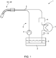
- the welding component cooling system 1 for cooling a welding component SK for example a welding torch SB, contains at least one container 2 for the cooling liquid 3.
- the cooling liquid 3 is formed in particular by water with appropriate additives, which is conducted from the container 2 in a cooling circuit 4.
- the cooling circuit 4 is formed by appropriate cooling lines 5 .
- At least one pump 6 arranged in the cooling circuit 4 conveys the cooling liquid 3 through the cooling lines 5 in the cooling circuit 4.
- At least one heat exchanger 7 is arranged within the cooling circuit 4 in a cooling line 5, via which the heat is dissipated to the environment.
- a device 8 for deionizing the cooling liquid 3 is provided in the cooling circuit 4 according to the invention.
- the deionization device 8 is in the returning cooling line 5 of the cooling circuit 4 arranged. However, it can also be placed at a different point within the cooling circuit 5 .
- the deionization device 8 which can be formed, for example, by a container 9 with mixed-bed resin 10 arranged therein (see FIG 3 ), ensures that the cooling liquid 3 has a very low electrical conductance S, as a result of which negative effects due to electrochemical oxidation taking place in the welding components SK have less of an impact and the welding components SK consequently have a longer service life.
- At least one sensor 14 for measuring the conductance S of the cooling liquid 3 is arranged in the cooling circuit 4, in particular in a cooling line 5 of the cooling circuit 4 that runs back.
- the condition of the cooling liquid 3 can be monitored via the measured values obtained from the sensor 14 for measuring the conductivity S of the cooling liquid 3 and the effect of the deionization by the deionizing device 8 can be measured.
- FIG. 2 shows a schematic block diagram of a further embodiment of a welding component cooling system 1 according to the invention.
- the device 8 for deionizing the cooling liquid 3 is not arranged in a cooling line 5 of the cooling circuit 4, but in a bypass 11 to a cooling line 5 within the cooling circuit 4.
- the flow resistance of the cooling liquid 3 within the cooling circuit 5 through the deionizing device 8 is not negatively influenced.
- the sensor 14 for measuring the conductivity S of the cooling liquid 3 at least one sensor 15 for measuring the flow Q of the cooling liquid 3 and at least one temperature sensor 16 for measuring the temperature T of the cooling liquid 3 are arranged in the cooling circuit 4.
- the sensors 14, 15, 16 are arranged at the same point within the cooling circuit 4 and are preferably formed by a combined sensor.
- the at least one sensor 14 for measuring the conductance S of the coolant 3, the at least one sensor 15 for measuring the Flow rate Q of the cooling liquid 3 and/or the at least one temperature sensor 16 for measuring the temperature T of the cooling liquid 3 and any sensor 21 for measuring the level of the cooling liquid 3 in the container 2 are preferably connected to a control device 17 which is responsible for processing and forwarding of the measured values.
- the measured values of the sensors 14, 15, 16, 21 and the status of the deionizing device 8 can be displayed on a display 18 connected to the control device 17.
- the control device 17 and the display 18 can also be arranged in a welding current source SQ.
- the connections between the control device 17 and the sensors 14, 15, 16, 21 can be wired or wireless.
- At least one filter 19 for filtering the cooling liquid 3 can also be arranged in the cooling circuit 4 .
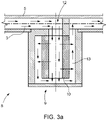
- FIG 3a an embodiment of a device for deionization 8 of the cooling liquid 3 is shown in the form of a container 9 with a mixed-bed resin 10 arranged therein.
- the cooling liquid 3 can on the one hand flow through the mixed-bed resin 10 and/or on the other hand only flow past the surface of the mixed-bed resin 10 in contact.
- the mixed-bed resin 10 can be exchanged in a simple manner, preferably from the underside of the container 9 .
- the mixed-bed resin 10 preferably consists of a mixture of cation resin and anion resin, in particular 40% cation salt and 60% anion salt.
- the Figure 3b and 3c show two further possible embodiments of the deionization device 8, in which the cooling liquid 3 in the container 9 flows past the surface of the mixed-bed resin 10 in contact with it.
- the 3d shows another possible embodiment of the deionizing device 8, the cooling liquid 3 flowing through the mixed-bed resin 10 in the container 9 on the one hand and or, on the other hand, can flow past the mixed-bed resin 10 only touching the surface.
- the welding torch SB has various components B1, B2, B3, B4, such as the nozzle holder as component B1, the gas nozzle holder as component B2, the cooling sleeve as component B3, the inner pipe of the pipe bend as component B4, etc.
- the components B1 and B4 consist of an electrically conductive material M1 and the component B3 consists of a different electrically conductive material M2.
- Component B3 consists of electrically insulating material M3.
- a cooling channel 20 for guiding a cooling liquid 3 runs inside the welding torch SB, which is correspondingly connected to the welding component cooling system 1 described above.
- the cooling channel 20 is partially formed by the above-mentioned components B1, B2, B3, B4 of the welding torch SB.
- the components B1, B2, B3, B4 are connected to one another, for example via a form fit, force fit or material bond.
- An electrochemical cell is thus formed via the cooling liquid 3 flowing in the cooling channel 20 .
- a cooling liquid 3 with a high electrical conductivity S promotes electrochemical oxidation of the anode (sacrificial anode) and thus destruction of the relevant components B1 and/or B2 and/or B4 of the welding torch SB made of the electrically conductive materials M1 and M2.
- various electrically conductive materials M1, M2 can be used for the components B1, B2, B4 of the welding torch SB, the standard potentials of the electrochemical series of which are more differ than 0.7 V.
- aluminum standard potential - 1.66 V
- silver standard potential +0.8 V
- FIG 5 a detailed view of the welding torch SB according to FIG figure 5 along the section line AA to illustrate the components B1, B2, B3, B4 in the area of the cooling channel 20.
- the electrically conductive components B1, B2, B4 of the welding torch SB are arranged in such a way that the minimum path length or liquid column length l min between the components B1 or B4 with component B2 through the cooling channel 20 is less than 12 mm, preferably less than 5 mm.
- the distance l x drawn in shows the distance to be covered by the cooling liquid 3, whereby the distance l x drawn in is more or less the straight line, i.e.
- the actual liquid column length l min is due to the design of the cooling channel 20 - the cooling liquid 3 follows the cooling channel 20 and thus forms a flow curve - significantly longer than that in figure 5 marked distance l x . It was not possible to produce a welding torch SB with the above-mentioned liquid column length l min of less than 12 mm, preferably less than 5 mm, when using conventional cooling liquids 3 .
- the present invention improves the cooling of the welding components SK and their service life and allows, as based on the figures 4 and 5 described, the use of new materials and material combinations for the components of the SK welding components and new designs.
Abstract
Die Erfindung betrifft ein Schweißkomponenten-Kühlsystem (1) zur Kühlung einer Schweißkomponente (SK, SB), insbesondere eines Schweißbrenners (SB), mit zumindest einem Behälter (2) für Kühlflüssigkeit (3), einem Kühlkeislauf (4) mit entsprechenden Kühlleitungen (5), zumindest einer im Kühlkreislauf (4) angeordneten Pumpe (6) zur Förderung der Kühlflüssigkeit (3) durch die Kühlleitungen (5) im Kühlkreislauf (4), und zumindest einem in einer Kühlleitung (5) angeordneten Wärmetauscher (7) sowie eine Schweißkomponente (SK), insbesondere einen Schweißbrenner (SB) mit einem solchen Schweißkomponenten-Kühlsystem (1). Zur Gewährleistung einer optimalen Kühlung und Erzielung einer möglichst hohen Lebensdauer der Schweißkomponente (SK) ist im Kühlkreislauf (4) eine Einrichtung (8) zur Deionisierung der Kühlflüssigkeit (3) vorgesehen.The invention relates to a welding component cooling system (1) for cooling a welding component (SK, SB), in particular a welding torch (SB), with at least one container (2) for coolant (3), a cooling circuit (4) with corresponding cooling lines (5 ), at least one pump (6) arranged in the cooling circuit (4) for conveying the cooling liquid (3) through the cooling lines (5) in the cooling circuit (4), and at least one heat exchanger (7) arranged in a cooling line (5) and a welding component (SK), in particular a welding torch (SB) with such a welding component cooling system (1). To ensure optimal cooling and to achieve the longest possible service life of the welding component (SK), a device (8) for deionizing the coolant (3) is provided in the cooling circuit (4).
Description
Die Erfindung betrifft ein Schweißkomponenten-Kühlsystem zur Kühlung einer Schweißkomponente, insbesondere eines Schweißbrenners, mit zumindest einem Behälter für Kühlflüssigkeit, einem Kühlkreislauf mit entsprechenden Kühlleitungen, zumindest einer im Kühlkreislauf angeordneten Pumpe zur Förderung der Kühlflüssigkeit durch die Kühlleitungen im Kühlkreislauf, und zumindest einem in einer Kühlleitung angeordneten Wärmetauscher.The invention relates to a welding component cooling system for cooling a welding component, in particular a welding torch, with at least one container for cooling liquid, a cooling circuit with corresponding cooling lines, at least one pump arranged in the cooling circuit for conveying the cooling liquid through the cooling lines in the cooling circuit, and at least one in a Cooling line arranged heat exchanger.
Weiters betrifft die Erfindung eine Schweißkomponente, insbesondere einen Schweißbrenner, mit einem oben genannten Schweißkomponenten-Kühlsystem.Furthermore, the invention relates to a welding component, in particular a welding torch, with a welding component cooling system mentioned above.
Die vorliegende Erfindung ist auf Schweißkomponenten bzw. deren Kühlung gerichtet, insbesondere auf Schutzgasschweißkomponenten.The present invention is aimed at welding components and their cooling, in particular at gas-shielded welding components.
Flüssigkeitskühlsysteme für Schweißvorrichtungen bestehen üblicherweise aus einer Pumpe, einer Kühlflüssigkeit, einer Kühlleitung, den zu kühlenden Schweißkomponenten, einem Behälter für die Kühlflüssigkeit, einem Wärmetauscher und optional einem Filter, einem Durchflusswächter und einer Einrichtung zur Messung der Temperatur der Kühlflüssigkeit. Die verwendeten Kühlflüssigkeiten basieren meist auf Wasser mit verschiedenen beigemengten Zusätzen. Derartige Kühlflüssigkeiten weisen in der Regel einen elektrischen Leitwert von 80-120 pS/m auf.Liquid cooling systems for welding devices usually consist of a pump, a cooling liquid, a cooling line, the welding components to be cooled, a container for the cooling liquid, a heat exchanger and optionally a filter, a flow switch and a device for measuring the temperature of the cooling liquid. The coolants used are usually based on water with various additives added. Such cooling liquids usually have an electrical conductivity of 80-120 pS/m.
Die Kühlleitungen und Kühlkanäle des Kühlkreislaufs weisen in der Regel unterschiedliche Materialien auf. Im Falle von elektrisch leitfähigen Materialien wie beispielsweise Metalle und/oder Metalllegierungen zeigen unterschiedliche Materialien unterschiedliche Standardpotentiale der elektrochemischen Spannungsreihe. Ferner können einzelne oder auch mehrere Bauteile im Kühlkreislauf gezielt bzw. ungezielt mit einer Spannung beaufschlagt werden und so auf unterschiedlichen elektrischen Potentialen (Kontaktrohrpfad/Gasdüsenpfad) liegen. Die resultierende Spannung zwischen Bestandteilen einer Schweißkomponente aus elektrisch leitfähigen Materialien kann zu einem elektrochemischen Stromfluss über die Kühlflüssigkeit führen. Des Weiteren können Konzentrationsgradienten von Ionen in der Kühlflüssigkeit auftreten, welche ebenfalls den Aufbau eines elektrochemischen Elements begünstigen. In der Folge resultiert ein sukzessiver Abbau des Bauteiles am Plus-Potential (Opferanode). Die Geschwindigkeit des Abbaus ist dabei unter anderem proportional zur Leitfähigkeit der Kühlflüssigkeit. Der elektrochemische Stromfluss baut dabei nicht nur die Anode ab und zerstört dadurch die jeweilige Schweißkomponente, sondern der dabei entstehende Anodenschlamm kann zudem die Kühlleitung verstopfen und somit die Kühlwirkung reduzieren oder sogar unterbinden. Da sich durch den elektrochemischen Oxidationsprozess in der Kühlflüssigkeit immer mehr Ionen ansammeln, steigt der Leitwert der Kühlflüssigkeit stetig an bzw. kann in eine Sättigung übergehen und der Prozess kann sich gegebenenfalls fortlaufend perpetuieren. Des Weiteren besitzen die abgelösten Ionen eine stark chemisch katalytische Wirkung, welche einen Zerfall der Kühlflüssigkeit in schwerlösliche, und somit verstopfende Substanzen begünstigt.The cooling lines and cooling channels of the cooling circuit usually have different materials. In the case of electrically conductive materials such as metals and/or metal alloys, different materials exhibit different standard potentials of the electrochemical series. Furthermore, individual or also several components in the cooling circuit can be subjected to a voltage in a targeted or non-targeted manner and are thus at different electrical potentials (contact tube path/gas nozzle path). The resulting voltage between parts of a welded component made of electrically conductive materials can lead to an electrochemical current flow through the cooling liquid. Furthermore, concentration gradients of ions can occur in the coolant, which also promote the build-up of an electrochemical element. As a result, a successive Removal of the component at the plus potential (sacrificial anode). The rate of degradation is proportional to the conductivity of the coolant, among other things. The electrochemical current flow not only breaks down the anode and thus destroys the respective welding component, but the resulting anode sludge can also clog the cooling line and thus reduce or even prevent the cooling effect. Since more and more ions accumulate in the cooling liquid as a result of the electrochemical oxidation process, the conductance of the cooling liquid increases steadily or can become saturated and the process can possibly continue continuously. Furthermore, the detached ions have a strong chemical-catalytic effect, which promotes the breakdown of the coolant into poorly soluble and thus clogging substances.
Zur Verringerung der elektrischen Leitfähigkeit einer Kühlflüssigkeit ist es in verschiedenen technischen Gebieten üblich, Deionisierer einzusetzen, welche die Ionen aus der Kühlflüssigkeit mit Hilfe eines Deionisierharzes entfernen. Beispielsweise beschreibt die
Der Einsatz einer Ionenaustauschharzeinheit zur Deionisierung der Kühlflüssigkeit in einer Brennstoffzelle wird beispielsweise in der
In Kühlsystemen von Schweißanlagen ist bislang der Einsatz von Einrichtungen zur Deionisierung der Kühlflüssigkeit nicht bekannt geworden.In the cooling systems of welding plants, the use of devices for deionizing the cooling liquid has hitherto not become known.
Die Aufgabe besteht daher in der Schaffung eines Schweißkomponenten-Kühlsystems sowie einer Schweißkomponente mit einem solchen Schweißkomponenten-Kühlsystem, durch welche eine optimale Kühlung der Schweißkomponente über möglichst lange Zeiträume gewährleistet wird und eine möglichst hohe Lebensdauer der Bestandteile der Schweißkomponente erzielt werden kann. Die verwendete Kühlflüssigkeit soll möglichst lange verwendet werden können und eine Verstopfung des Kühlkreislaufes verhindert werden. Nachteile bekannter Schweißkomponenten-Kühlsysteme sollen verringert oder sogar eliminiert werden.The task is therefore to create a welding component cooling system and a welding component with such a welding component cooling system, through which optimal cooling of the welding component is guaranteed over the longest possible periods of time and the longest possible service life of the components of the welding component can be achieved. The coolant used should be used for as long as possible and blockage of the cooling circuit can be prevented. Disadvantages of known welding component cooling systems should be reduced or even eliminated.
Gelöst wird die erfindungsgemäße Aufgabe durch ein oben genanntes Schweißkomponenten-Kühlsystem, bei dem im Kühlkreislauf eine Einrichtung zur Deionisierung der Kühlflüssigkeit vorgesehen ist. Durch die im Kühlkreislauf angeordnete Deionisiereinrichtung wird gewährleistet, dass die Leitfähigkeit der Kühlflüssigkeit gering bleibt, sodass die oben beschriebenen Nachteile der rascheren Zerstörung von metallischen Bestandteilen der jeweiligen Schweißkomponente durch den elektrochemischen Oxidationsprozess und dadurch verringerten Standzeit der Schweißkomponente sowie der Verschmutzung der Kühlflüssigkeit und einer allfälligen Blockierung des Kühlkreislaufes nicht oder nicht so rasch eintreten. Im Kühlkreislauf befindet sich also zumindest eine Deionisiereinrichtung, welche eine Entsalzung der Kühlflüssigkeit bewirkt. Durch die resultierende Reduktion des Leitwertes der Kühlflüssigkeit wird die elektrochemische Korrosion der metallischen Bestandteile verringert oder vorzugsweise ganz gestoppt und die Lebensdauer der Schweißkomponenten bzw. deren Bestandteile drastisch erhöht. Zu den Schweißkomponenten zählt in erster Linie der Schweißbrenner, aber auch das Schlauchpaket, durch welches die Kühlflüssigkeit in entsprechenden Leitungen geführt wird, die Pumpe für die Förderung der Kühlflüssigkeit, etc. Durch das erfindungsgemäße Schweißkomponenten-Kühlsystem und die reduzierte Leitfähigkeit der Kühlflüssigkeit können für manche Schweißkomponenten oder deren Bestandteile Materialien verwendet werden, welche bei herkömmlichen Kühlflüssigkeiten ohne die gegenständliche Erfindung binnen kürzester Zeit zur Zerstörung führen würden. Der Aufwand und die Kosten für die Implementierung der Deionisiereinrichtung im Kühlkreislauf sind überschaubar und amortisieren sich durch die erzielte längere Lebensdauer der Schweißkomponenten relativ rasch.The object according to the invention is achieved by an above-mentioned cooling system for welding components, in which a device for deionizing the cooling liquid is provided in the cooling circuit. The deionization device arranged in the cooling circuit ensures that the conductivity of the cooling liquid remains low, so that the above-described disadvantages of the faster destruction of metallic components of the respective welding component by the electrochemical oxidation process and the resulting reduced service life of the welding component as well as contamination of the cooling liquid and any blockage of the cooling circuit does not occur or does not occur as quickly. There is at least one deionization device in the cooling circuit, which causes desalination of the cooling liquid. The resulting reduction in the conductance of the cooling liquid reduces or preferably completely stops the electrochemical corrosion of the metallic components and drastically increases the service life of the welding components or their components. The welding components primarily include the welding torch, but also the hose package through which the coolant is routed in the appropriate lines, the pump for conveying the coolant, etc. Due to the welding component cooling system according to the invention and the reduced conductivity of the coolant, for some Welding components or their parts are made of materials that would lead to destruction within a very short time in the case of conventional cooling liquids without the present invention. The effort and costs for implementing the deionization device in the cooling circuit are manageable and amortize relatively quickly thanks to the longer service life of the welding components.
Vorzugsweise ist die Deioisiereinrichtung durch einen Behälter mit darin angeordnetem Mischbettharz gebildet. Dies stellt eine einfache und kostengünstige Realisierungsmöglichkeit einer Einrichtung zur Deionisierung der Kühlflüssigkeit dar. Das sehr günstig erhältliche Mischbettharz wird in einem Behälter, der von der Kühlflüssigkeit durchströmt wird, angeordnet, wodurch es zu einer Entsalzung der Kühlflüssigkeit kommt. Das Harz bindet die freien Ionen in der Kühlflüssigkeit und reduziert damit den Leitwert der Kühlflüssigkeit je nach Menge und Platzierung. Beispielsweise sind Leitwerte der Kühlflüssigkeit in der Größenordnung von 1 - 50 pS/m erzielbar. Der durch das Mischbettharz gebildete Ionentauscher ist geeignet, (Metall-)Ionen "einzufangen" oder einzulagern und durch H+ bzw. OH- Ionen zu ersetzen, welche in weiterer Folge zu neutralem Wasser kombinieren. Geeignet als Mischbettharze sind insbesondere OH- und H+ Ionen aktivierte Harze, beispielsweise Purolite® MB400, Universalmischbettharze oder selektive Mischbettharze, welche auch in beliebigem Verhältnis miteinander gemischt werden können und unterschiedliche Korngrößen aufweisen können. Eine Wiederaufbereitung der Mischbettharze ist nicht vorgesehen.The deionizing device is preferably formed by a container with mixed-bed resin arranged therein. This represents a simple and inexpensive way of realizing a device for deionizing the cooling liquid is flowed through by the cooling liquid, arranged, which leads to a desalination of the cooling liquid. The resin binds the free ions in the cooling liquid and thus reduces the conductance of the cooling liquid depending on the amount and placement. For example, conductance values of the coolant in the order of 1 - 50 pS/m can be achieved. The ion exchanger formed by the mixed-bed resin is suitable for "capturing" or storing (metal) ions and replacing them with H+ or OH- ions, which subsequently combine to form neutral water. Particularly suitable as mixed-bed resins are OH- and H+ ion-activated resins, for example Purolite® MB400, universal mixed-bed resins or selective mixed-bed resins, which can also be mixed with one another in any ratio and can have different grain sizes. A reprocessing of the mixed-bed resins is not planned.
Das im Behälter der Deionisiereinrichtung angeordnete Mischbettharz kann idealerweise aus einer Mischung von Kationenharz und Anionenharz, vorzugsweise 40% Kationensalz und 60% Anionensalz bestehen. Das Mischungsverhältnis zwischen Anionensalz und Kationensalz wird in der Regel derart gewählt, sodass die Standzeit des Mischbettharzes maximiert wird.The mixed-bed resin arranged in the tank of the deionizer can ideally consist of a mixture of cation resin and anion resin, preferably 40% cation salt and 60% anion salt. The mixing ratio between anion salt and cation salt is usually selected in such a way that the service life of the mixed-bed resin is maximized.
Die Deionisiereinrichtung kann in einer Kühlleitung innerhalb des Kühlkreislaufes angeordnet sein. Dadurch wird die Deionisiereinrichtung von der Kühlflüssigkeit durchflossen und diese dadurch deionisiert und deren Leitwert reduziert.The deionizing device can be arranged in a cooling line within the cooling circuit. As a result, the cooling liquid flows through the deionizing device, thereby deionizing it and reducing its conductance.
Alternativ dazu kann die Deionisiereinrichtung auch in einem Bypass zu einer Kühlleitung innerhalb des Kühlkreislaufes angeordnet sein. Dies hat gegenüber der oben beschriebenen Anordnung direkt im Kühlkreislauf den Vorteil, dass durch die Deionisiereinrichtung keine Erhöhung des Strömungswiderstands für die Kühlflüssigkeit im Kühlkreislauf bewirkt wird, die Leitfähigkeit der Kühlflüssigkeit aber dennoch entsprechend reduziert werden kann.As an alternative to this, the deionization device can also be arranged in a bypass to a cooling line within the cooling circuit. Compared to the above-described arrangement directly in the cooling circuit, this has the advantage that the deionization device does not increase the flow resistance for the cooling liquid in the cooling circuit, but the conductivity of the cooling liquid can nevertheless be correspondingly reduced.
Gemäß einem Merkmal der Erfindung weist der Behälter mit dem Mischbettharz einen zentralen Einlasskanal und koaxial dazu außen einen Abflusskanal auf. Die Kühlflüssigkeit kann einerseits durch das Mischbettharz hindurchströmen und/oder andererseits lediglich die Oberfläche berührend am Mischbettharz vorbeiströmen. Dieser Aufbau gewährleistet eine optimale Wechselwirkung des im Behälter angeordneten Mischbettharzes mit der Kühlflüssigkeit bei gleichzeitig möglichst geringem Strömungswiderstand für die Kühlflüssigkeit.According to a feature of the invention, the container with the mixed-bed resin has a central inlet channel and an outflow channel coaxial thereto. The coolant can on the one hand flow through the mixed-bed resin and/or, on the other hand, only flow past the surface touching the mixed-bed resin. This structure ensures an optimal interaction of the mixed-bed resin arranged in the container with the cooling liquid while at the same time the lowest possible flow resistance for the cooling liquid.
Wenn zumindest ein Sensor zur Messung des Leitwerts der Kühlflüssigkeit im Kühlkreislauf angeordnet ist, kann der Zustand der Kühlflüssigkeit überprüft werden und es können bei bestimmten Leitwerten entsprechende Warnungen ausgegeben oder automatisch Regelungen vorgenommen werden. Bei Erreichung eines vorgegebenen Grenzwerts für die Leitfähigkeit kann dies beispielsweise ein Anzeichen für eine Sättigung des Mischbettharzes der Deionisiereinrichtung sein. Dementsprechend kann über eine Steuereinrichtung und eine Anzeige der Schweißer zu einem Wechsel des Mischbettharzes angeregt werden. Hierbei kann eine einfache Wechselmöglichkeit der Deionisiereinrichtung beispielsweise durch eine Schraubverbindung, eine Klickverbindung oder eine Bajonettverbindung vorgesehen sein. Anstelle einer eigenen dafür vorgesehenen Anzeige kann auch die Anzeige an der Schweißstromquelle oder an einer übergeordneten Steuereinrichtung verwendet werden, welche über entsprechende Verbindungsleitungen mit dem zumindest einen Leitwertsensor verbunden ist. Dabei sind sowohl drahtgebundene als auch drahtlose Verbindungen möglich. Beispielsweise können folgende Grenzwerte für den Leitwert der Kühlflüssigkeit definiert werden:
Dabei ist zumindest ein Sensor zur Messung des Leitwerts der Kühlflüssigkeit vorzugsweise in einer rücklaufenden Kühlleitung des Kühlkreislaufes angeordnet.At least one sensor for measuring the conductance of the cooling liquid is preferably arranged in a returning cooling line of the cooling circuit.
Weiters kann zumindest ein Sensor zur Messung des Durchflusses der Kühlflüssigkeit im Kühlkreislauf angeordnet sein, wodurch wichtige Informationen über die Strömung der Kühlflüssigkeit gewonnen werden können. Die gemessenen Durchflusswerte der Kühlflüssigkeit können einerseits zu Dokumentations- oder Überwachungszwecken verwendet werden oder auch zur Regelung bestimmter Vorgänge verwendet werden. Der oben erwähnte Sensor zur Messung der Leitfähigkeit der Kühlflüssigkeit kann in besonders bevorzugter Weise auch mit dem Sensor zur Messung des Durchflusses der Kühlflüssigkeit kombiniert werden und an einer oder auch an mehreren Stellen im Kühlkreislauf platziert werden. Derartige kombinierte Sensoren für beide Eigenschaften der Kühlflüssigkeit sind relativ kostengünstig und in geringer Baugröße erhältlich.Furthermore, at least one sensor for measuring the flow of the cooling liquid can be arranged in the cooling circuit, as a result of which important information about the flow of the cooling liquid can be obtained. The measured flow values of the cooling liquid can be used for documentation or monitoring purposes, or they can also be used to regulate certain processes. The above-mentioned sensor for measuring the conductivity of the coolant can also be combined in a particularly preferred manner with the sensor for measuring the flow of the coolant and placed at one or more points in the cooling circuit. Such combined sensors for both properties of the coolant are relatively inexpensive and available in small sizes.
Über zumindest einen Temperatursensor kann die Temperatur der Kühlflüssigkeit im Kühlkreislauf erfasst werden. Über die Temperatur der Kühlflüssigkeit kann natürlich die Kühlwirkung gemessen und es können entsprechende Schritte gesetzt werden. Die gemessene Temperatur der Kühlflüssigkeit kann einerseits zu Dokumentations- oder Überwachungszwecken oder auch zur Regelung bestimmter Vorgänge herangezogen werden. Die oben erwähnte Sensor zur Messung der Leitfähigkeit der Kühlflüssigkeit und Sensor zur Messung des Durchflusses der Kühlflüssigkeit kann in besonders bevorzugter Weise auch mit dem Sensor zur Messung der Temperatur der Kühlflüssigkeit kombiniert werden und an einer oder auch an mehreren Stellen im Kühlkreislauf platziert werden. Derartige kombinierte Sensoren für alle genannten Eigenschaften sind relativ kostengünstig und in geringer Baugröße erhältlich.The temperature of the cooling liquid in the cooling circuit can be detected via at least one temperature sensor. The cooling effect can of course be measured via the temperature of the cooling liquid and appropriate steps can be taken. The measured temperature of the cooling liquid can be used on the one hand for documentation or monitoring purposes or also for controlling certain processes. The above-mentioned sensor for measuring the conductivity of the cooling liquid and sensor for measuring the flow of the cooling liquid can also be combined with the sensor for measuring the temperature of the cooling liquid in a particularly preferred manner and placed at one or more points in the cooling circuit. Such combined sensors for all the properties mentioned are relatively inexpensive and available in small sizes.
Der zumindest eine Sensor zur Messung des Leitwerts der Kühlflüssigkeit, der zumindest eine Sensor zur Messung des Durchflusses der Kühlflüssigkeit, und bzw. oder der zumindest eine Temperatursensor zur Messung der Temperatur der Kühlflüssigkeit oder ein entsprechender Kombinationssensor kann mit einer Steuereinrichtung verbunden sein. Die Steuereinrichtung, welche beispielsweise durch einen Mikroprozessor gebildet sein kann, verarbeitet die Daten entsprechend und leitet diese an die gewünschten übergeordneten Stellen weiter. Anstelle einer eigenen dafür vorgesehenen Steuereinrichtung kann natürlich auch eine beispielsweise in einer Schweißstromquelle ohnedies vorhandene Steuereinrichtung verwendet werden. Voraussetzung dafür ist nur eine entsprechende drahtgebundene oder drahtlose Verbindung der jeweiligen Sensoren mit dieser Steuereinrichtung und die Gewährleistung einer Versorgung der Sensoren mit elektrischer Energie.The at least one sensor for measuring the conductance of the cooling liquid, the at least one sensor for measuring the flow of the cooling liquid, and/or the at least one temperature sensor for measuring the temperature of the cooling liquid or a corresponding combination sensor can be connected to a control device. The control device, which, for example can be formed by a microprocessor, processes the data accordingly and forwards them to the desired higher-level bodies. Instead of a separate control device provided for this purpose, a control device that is already present in a welding current source, for example, can of course also be used. The only requirement for this is a corresponding wired or wireless connection of the respective sensors to this control device and the guarantee of a supply of electrical energy to the sensors.
Die Steuereinrichtung ist vorzugsweise mit einer Anzeige verbunden, um dem Benutzer des Schweißkomponenten-Kühlsystems Betriebszustände optisch anzeigen zu können. Die Anzeige kann von einfachen Lichtquellen, insbesondere Leuchtdioden über einfache Displays bis hin zu komplexeren Touch-Screens, welche gleichzeitig eine Bedienfunktion ermöglichen, reichen. Über die Anzeige kann beispielsweise auch der jeweilige Zustand der Deionisiereinrichtung, der Leitwert, Durchfluss und/oder die Temperatur der Kühlflüssigkeit, etc. in unterschiedlichen Farben, Zahlenwerten oder auch in Form von Zeigern dargestellt werden. Im Falle der Überschreitung bestimmter Grenzwerte können neben optischen Warnungen natürlich auch akustische Signale über einen Lautsprecher oder dgl. abgegeben werden und bzw. oder an übergeordnete Zentralen weitergeleitet werden.The control device is preferably connected to a display in order to be able to visually display operating states to the user of the welding component cooling system. The display can range from simple light sources, in particular light-emitting diodes, through simple displays to more complex touch screens, which at the same time enable an operating function. For example, the respective status of the deionization device, the conductance, flow rate and/or the temperature of the cooling liquid, etc., can also be shown on the display in different colors, numerical values or in the form of pointers. If certain limit values are exceeded, of course, in addition to visual warnings, acoustic signals can also be emitted via a loudspeaker or the like and/or forwarded to higher-level control centers.
Wenn die Steuereinrichtung mit einer mit der Schweißkomponente verbundenen Schweißstromquelle verbindbar ist, kann die Schweißstromquelle zur Anzeige oder Verarbeitung der relevanten Informationen herangezogen werden und es muss keine eigene Steuereinrichtung und allenfalls Anzeige bereitgestellt werden.If the control device can be connected to a welding power source connected to the welding component, the welding power source can be used to display or process the relevant information and no separate control device or display need be provided.
Als Kühlflüssigkeit ist vorzugsweise Wasser mit Zusätzen, beispielsweise einem Frostschutzmittel, insbesondere Ethanol oder Propylenglykol oder Ethylenglykol oder allgemeine wasserlösliche Alkohole und bzw. oder allgemeine wasserlösliche Polyalkohole, und bzw. oder einem Korrosionsinhibitor, vorgesehen. Ferner können der Kühlflüssigkeit noch Algizide und bzw. oder Fungizide beigemengt sein.Water with additives, for example an antifreeze, in particular ethanol or propylene glycol or ethylene glycol or general water-soluble alcohols and/or general water-soluble polyalcohols and/or a corrosion inhibitor is preferably provided as the coolant. Furthermore, algaecides and/or fungicides can also be added to the coolant.
Wenn im Kühlkreislauf zumindest ein Filter angeordnet ist, können Verunreinigungen in der Kühlflüssigkeit abgeschieden werden. Als Filter können beispielsweise Metallsiebe, Kunststoffsiebe, Papier- bzw. Naturfaserfilter, Filze, Vliese, offenporige Sintermaterialien, Schüttungen oder Kombinationen daraus eingesetzt werden. Sinkt der Durchfluss der Kühlflüssigkeit unter einen vorgegebenen Grenzwert, kann dies ein Anzeichen für einen höheren Verschmutzungsgrad des Filters sein und ein Tausch oder eine Reinigung des Filters notwendig werden.If at least one filter is arranged in the cooling circuit, impurities in the cooling liquid can be separated. For example, metal screens, plastic screens, paper or natural fiber filters, felts, nonwovens, open-pored sintered materials, beds or combinations thereof can be used as filters. If the coolant flow falls below a specified limit value, this can be an indication of a higher degree of contamination of the filter and it may be necessary to replace or clean the filter.
Gelöst wird die erfindungsgemäße Aufgabe auch durch eine oben erwähnte Schweißkomponente, insbesondere einen Schweißbrenner, bei der ein oben beschriebenes Schweißkomponenten-Kühlsystem vorgesehen ist, dessen Kühlkreislauf mit dem Kühlkanal der Schweißkomponente verbunden ist bzw. wobei der Kühlkanal der Schweißkomponente Teil des Kühlkreislaufes des Schweißkomponenten-Kühlsystems ist. Durch den Einsatz des erfindungsgemäßen Kühlsystems wird gewährleistet, dass die Kühlflüssigkeit einen möglichst geringen Leitwert aufweist und dadurch die elektrochemische Oxidation vermieden oder reduziert wird. Zu den weiteren erzielbaren Vorteilen wird auf die obige Beschreibung des Schweißkomponenten-Kühlsystems verwiesen.
Erfindungsgemäß können durch den niedrigen Leitwert der Kühlflüssigkeit unterschiedliche Materialen mit einer Differenz des elektrochemischen Potentials von größer als 0,7 V, in einer Schweißkomponente, insbesondere eines Schweißbrenners verwendet werden. Die Lebensdauer wird durch den geringen elektrochemischen Stromfluss, auf Grund der niedrigen Leitfähigkeit der Kühlflüssigkeit, nicht verringert.The object according to the invention is also achieved by an above-mentioned welding component, in particular a welding torch, in which a welding component cooling system as described above is provided, the cooling circuit of which is connected to the cooling channel of the welding component or the cooling channel of the welding component is part of the cooling circuit of the welding component cooling system is. The use of the cooling system according to the invention ensures that the cooling liquid has the lowest possible conductance and as a result electrochemical oxidation is avoided or reduced. For the other advantages that can be achieved, reference is made to the above description of the welding component cooling system.
According to the invention, due to the low conductance of the coolant, different materials with a difference in electrochemical potential of more than 0.7 V can be used in a welding component, in particular a welding torch. The service life is not reduced by the low electrochemical current flow due to the low conductivity of the cooling liquid.
Wie bereits oben erwähnt, ist durch die Erzielung der sehr niedrig leitfähigen Kühlflüssigkeit die Verwendung von Metallen und deren Kombinationen möglich, welche andernfalls zu einer raschen Zerstörung der Bestandteile führen würden. Während beispielsweise bei herkömmlichen Schweißkomponenten-Kühlsystemen, bei welchen die Kühlflüssigkeit relativ hohe elektrische Leitwerte aufweisen, Bestandteile aus elektrisch leitfähigen Materialien mit einem ähnlichen Standardpotential nach der elektrochemischen Spannungsreihe aufweisen, sind bei Verwendung des erfindungsgemäßen Schweißkomponenten-Kühlsystems auch Kombinationen von Materialien mit einem deutlich höheren Unterschied des Standardpotentials nach der elektrochemischen Spannungsreihe verwendbar. Beispielsweise war, unter Einhaltung der geforderten Standzeit, bei herkömmlichen wassergekühlten Schweißkomponenten nur die Kombination von Metallen mit maximal 0,58 V Unterschied im Standardpotential möglich, beispielsweise die Verwendung von Kupfer (Standardpotential +0,35 V) und Nickel (Standardpotential -0,23 V). Bei Einsatz des erfindungsgemäßen Schweißkomponenten-Kühlsystems hingegen ist beispielsweise unter Einhaltung der geforderten Standzeit, die Kombination von Metallen mit bis zu 2,46 V Unterschied im Standardpotential möglich. Hier kann beispielsweise Aluminium (Standardpotential -1,66V) mit Silber (Standardpotential +0,8V) kombiniert werden und dadurch eine wesentlich höhere Lebensdauer der Schweißkomponente, insbesondere des Schweißbrenners erzielt werden.As already mentioned above, the achievement of the very low conductivity cooling liquid allows the use of metals and their combinations, which would otherwise lead to rapid destruction of the components. While, for example, in conventional welding component cooling systems, in which the cooling liquid has relatively high electrical conductance values, components made of electrically conductive materials have a similar standard potential according to the electrochemical series, when using the Welding component cooling system combinations of materials with a significantly higher difference in the standard potential according to the electrochemical series can also be used. For example, while maintaining the required service life, with conventional water-cooled welding components only the combination of metals with a maximum difference of 0.58 V in the standard potential was possible, for example the use of copper (standard potential +0.35 V) and nickel (standard potential -0.23 v). When using the welding component cooling system according to the invention, on the other hand, the combination of metals with a difference in standard potential of up to 2.46 V is possible, for example, while maintaining the required service life. Here, for example, aluminum (standard potential -1.66V) can be combined with silver (standard potential +0.8V), thereby achieving a significantly longer service life for the welding component, in particular the welding torch.
Gemäß einem weiteren Merkmal der Erfindung ist vorgesehen, dass die zumindest zwei Bestandteile der Schweißkomponente mit unterschiedlichem elektrochemischen Standardpotential, derart angeordnet sind, dass die minimale Weglänge bzw. die Flüssigkeitssäulenlänge zwischen den zumindest zwei Bestandteilen durch den Kühlkanal unter 12 mm, vorzugsweise unter 5 mm, beträgt. Bei Schweißkomponenten mit herkömmlichen Kühlsystemen mit Leitwerten der Kühlflüssigkeit zwischen 50 und 250 µS besteht die Anforderung beispielsweise darin, die Flüssigkeitssäulenlänge > 12 mm auszuführen, um eine noch akzeptable elektrochemische Abtragsrate zu gewährleisten. Beim Einsatz des erfindungsgemäßen Kühlsystems mit Leitwerten der Kühlflüssigkeit unter 10 µS genügen hingegen Flüssigkeitssäulenlängen < 5 mm zur Erzielung einer noch akzeptablen elektrochemischen Abtragsrate. Dadurch können manche Schweißkomponenten auch kompakter bzw. leichter ausgeführt werden.According to a further feature of the invention, it is provided that the at least two components of the welding component with different electrochemical standard potentials are arranged in such a way that the minimum path length or the liquid column length between the at least two components through the cooling channel is less than 12 mm, preferably less than 5 mm. amounts to. In the case of welded components with conventional cooling systems with conductance values of the cooling liquid between 50 and 250 µS, the requirement is, for example, that the liquid column length be > 12 mm in order to ensure an electrochemical removal rate that is still acceptable. On the other hand, when using the cooling system according to the invention with conductance values of the cooling liquid below 10 μS, liquid column lengths of <5 mm are sufficient to achieve an electrochemical removal rate that is still acceptable. As a result, some welding components can also be made more compact or lighter.
Die vorliegende Erfindung wird anhand der beigefügten Zeichnungen, auf die sie nicht beschränkt sein soll, näher erläutert. Darin zeigen:
- Fig. 1
- ein schematisches Blockschaltbild einer Ausführungsform eines erfindungsgemäßen Schweißkomponenten-Kühlsystems;
- Fig. 2
- ein schematisches Blockschaltbild einer weiteren Ausführungsform eines erfindungsgemäßen Schweißkomponenten-Kühlsystems;
- Fig. 3a
- eine erste Ausführungsform einer Einrichtung zur Deionisierung der Kühlflüssigkeit in Form eines Behälters mit darin angeordnetem Mischbettharz;
- Fig. 3b
- eine zweite Ausführungsform einer Einrichtung zur Deionisierung der Kühlflüssigkeit in Form eines Behälters mit darin angeordnetem Mischbettharz;
- Fig. 3c
- eine dritte Ausführungsform einer Einrichtung zur Deionisierung der Kühlflüssigkeit in Form eines Behälters mit darin angeordnetem Mischbettharz;
- Fig. 3d
- eine vierte Ausführungsform einer Einrichtung zur Deionisierung der Kühlflüssigkeit in Form eines Behälters mit darin angeordnetem Mischbettharz;
- Fig. 4
- eine schematisches Schnittbild durch einen Schweißbrenner zur Verbindung mit einem erfindungsgemäßen Schweißkomponenten-Kühlsystem; und
- Fig. 5
- eine Detailansicht eines Schweißbrenners im Schnittbild A-A zur Veranschaulichung der Bestandteile im Bereich des Kühlkanals.
- 1
- a schematic block diagram of an embodiment of a welding component cooling system according to the invention;
- 2
- a schematic block diagram of a further embodiment of a welding component cooling system according to the invention;
- Figure 3a
- a first embodiment of a device for deionizing the cooling liquid in the form of a container with mixed-bed resin arranged therein;
- Figure 3b
- a second embodiment of a device for deionizing the cooling liquid in the form of a container with mixed-bed resin arranged therein;
- 3c
- a third embodiment of a device for deionizing the cooling liquid in the form of a container with mixed-bed resin arranged therein;
- 3d
- a fourth embodiment of a device for deionizing the cooling liquid in the form of a container with mixed-bed resin arranged therein;
- 4
- a schematic sectional view through a welding torch for connection to a welding component cooling system according to the invention; and
- figure 5
- a detailed view of a welding torch in section AA to illustrate the components in the area of the cooling channel.
In
Die Deionisiereinrichtung 8, welche beispielsweise durch einen Behälter 9 mit darin angeordnetem Mischbettharz 10 gebildet sein kann (siehe
Vorteilhafterweise ist zumindest ein Sensor 14 zur Messung des Leitwerts S der Kühlflüssigkeit 3 im Kühlkreislauf 4, insbesondere in einer rücklaufenden Kühlleitung 5 des Kühlkreislaufes 4 angeordnet. Über die erhaltenen Messwerte des Sensors 14 zur Messung des Leitwerts S der Kühlflüssigkeit 3 kann der Zustand der Kühlflüssigkeit 3 überwacht und die Wirkung der Deionisierung durch die Deionisiereinrichtung 8 gemessen werden.Advantageously, at least one
Der zumindest eine Sensor 14 zur Messung des Leitwerts S der Kühlflüssigkeit 3, der zumindest eine Sensor 15 zur Messung des Durchflusses Q der Kühlflüssigkeit 3, und bzw. oder der zumindest eine Temperatursensor 16 zur Messung der Temperatur T der Kühlflüssigkeit 3 sowie ein allfälliger Sensor 21 zur Messung des Pegels der Kühlflüssigkeit 3 im Behälter 2 sind vorzugsweise mit einer Steuereinrichtung 17 verbunden, welche für die Verarbeitung und Weiterleitung der Messwerte sorgt. An einer mit der Steuereinrichtung 17 verbundenen Anzeige 18 können die Messwerte der Sensoren 14, 15, 16, 21 angezeigt und der Zustand der Deionisiereinrichtung 8 dargestellt werden. Die Steuereinrichtung 17 sowie die Anzeige 18 können auch in einer Schweißstromquelle SQ angeordnet sein. Die Verbindungen zwischen der Steuereinrichtung 17 und den Sensoren 14, 15, 16, 21 können leitungsgebunden oder auch drahtlos ausgeführt sein.The at least one
Im Kühlkreislauf 4 kann auch zumindest ein Filter 19 zum Filtrieren der Kühlflüssigkeit 3 angeordnet sein.At least one
In
Die
Die
Dadurch, dass die Kühlflüssigkeit 3 gemäß der Erfindung deionisiert wird und einen sehr geringen elektrischen Leitwert S aufweist, können für die Bestandteile B1, B2, B4 des Schweißbrenners SB verschiedene elektrisch leitfähige Materialien M1, M2 verwendet werden, deren Standardpotentiale der elektrochemischen Spannungsreihe sich um mehr als 0,7 V unterscheiden. Wie weiter oben erwähnt, kann beispielsweise Aluminium (Standardpotential - 1,66 V) mit Silber (Standardpotential +0,8 V) kombiniert werden, was bei herkömmlichen wassergekühlten Schweißkomponenten SK nicht möglich war.Because the cooling
Schließlich zeigt
Die vorliegende Erfindung verbessert die Kühlung der Schweißkomponenten SK sowie deren Lebensdauer und ermöglicht, wie anhand der
Claims (15)
Priority Applications (4)
| Application Number | Priority Date | Filing Date | Title |
|---|---|---|---|
| EP21182634.2A EP4112218A1 (en) | 2021-06-30 | 2021-06-30 | Welding component cooling system with a device for deionising the cooling liquid, and welding component comprising such a welding component cooling system |
| CN202280016888.0A CN116940434A (en) | 2021-06-30 | 2022-06-29 | Welding component cooling system with coolant-specifying device and welding component including the same |
| EP22738638.0A EP4255663A1 (en) | 2021-06-30 | 2022-06-29 | Welding component cooling system with a device for designating the cooling liquid, and welding component comprising such a welding component cooling system |
| PCT/EP2022/067824 WO2023275107A1 (en) | 2021-06-30 | 2022-06-29 | Welding component cooling system with a device for designating the cooling liquid, and welding component comprising such a welding component cooling system |
Applications Claiming Priority (1)
| Application Number | Priority Date | Filing Date | Title |
|---|---|---|---|
| EP21182634.2A EP4112218A1 (en) | 2021-06-30 | 2021-06-30 | Welding component cooling system with a device for deionising the cooling liquid, and welding component comprising such a welding component cooling system |
Publications (1)
| Publication Number | Publication Date |
|---|---|
| EP4112218A1 true EP4112218A1 (en) | 2023-01-04 |
Family
ID=76730292
Family Applications (2)
| Application Number | Title | Priority Date | Filing Date |
|---|---|---|---|
| EP21182634.2A Withdrawn EP4112218A1 (en) | 2021-06-30 | 2021-06-30 | Welding component cooling system with a device for deionising the cooling liquid, and welding component comprising such a welding component cooling system |
| EP22738638.0A Pending EP4255663A1 (en) | 2021-06-30 | 2022-06-29 | Welding component cooling system with a device for designating the cooling liquid, and welding component comprising such a welding component cooling system |
Family Applications After (1)
| Application Number | Title | Priority Date | Filing Date |
|---|---|---|---|
| EP22738638.0A Pending EP4255663A1 (en) | 2021-06-30 | 2022-06-29 | Welding component cooling system with a device for designating the cooling liquid, and welding component comprising such a welding component cooling system |
Country Status (3)
| Country | Link |
|---|---|
| EP (2) | EP4112218A1 (en) |
| CN (1) | CN116940434A (en) |
| WO (1) | WO2023275107A1 (en) |
Citations (6)
| Publication number | Priority date | Publication date | Assignee | Title |
|---|---|---|---|---|
| EP0072407A2 (en) | 1981-08-14 | 1983-02-23 | The Perkin-Elmer Corporation | Plasma spray gun cooling fin nozzle |
| JPS5917617A (en) * | 1982-07-22 | 1984-01-28 | Toshiba Corp | Device for controlling ph of cooling water |
| US4560856A (en) * | 1982-09-01 | 1985-12-24 | Westinghouse Electric Corp. | Pulsed laser machining apparatus |
| EP2025029B1 (en) | 2006-05-05 | 2011-12-14 | Fronius International GmbH | Cooling system for a fuel cell |
| EP3501719A1 (en) * | 2017-12-22 | 2019-06-26 | FRONIUS INTERNATIONAL GmbH | Welding device with exchangeable cooled welding torch and/or hose assembly and method for changing the cooled welding torch and/or hose assembly |
| US20210078115A1 (en) * | 2017-09-19 | 2021-03-18 | Alexander Binzel Schweisstechnik Gmbh & Co. Kg | Torch body for thermal joining |
Family Cites Families (6)
| Publication number | Priority date | Publication date | Assignee | Title |
|---|---|---|---|---|
| DE19934367C2 (en) * | 1999-07-22 | 2003-08-21 | Binzel Alexander Gmbh Co Kg | Process for cooling a welding or cutting torch and cooling system therefor |
| DE10104771A1 (en) * | 2001-02-02 | 2002-08-08 | Basf Ag | Method and device for deionizing cooling media for fuel cells |
| JP3979580B2 (en) * | 2002-05-31 | 2007-09-19 | 本田技研工業株式会社 | Fuel cell cooling system |
| JP2005345076A (en) * | 2004-06-07 | 2005-12-15 | Daikin Ind Ltd | Cooling device |
| US20100276397A1 (en) * | 2009-05-01 | 2010-11-04 | Baker Hughes Incorporated | Electrically isolated gas cups for plasma transfer arc welding torches, and related methods |
| CN103928840B (en) * | 2013-01-15 | 2017-05-17 | 沈阳大陆激光柔性制造技术有限公司 | High purity water cooling device of semiconductor laser unit |
-
2021
- 2021-06-30 EP EP21182634.2A patent/EP4112218A1/en not_active Withdrawn
-
2022
- 2022-06-29 EP EP22738638.0A patent/EP4255663A1/en active Pending
- 2022-06-29 CN CN202280016888.0A patent/CN116940434A/en active Pending
- 2022-06-29 WO PCT/EP2022/067824 patent/WO2023275107A1/en active Application Filing
Patent Citations (7)
| Publication number | Priority date | Publication date | Assignee | Title |
|---|---|---|---|---|
| EP0072407A2 (en) | 1981-08-14 | 1983-02-23 | The Perkin-Elmer Corporation | Plasma spray gun cooling fin nozzle |
| US4405853A (en) * | 1981-08-14 | 1983-09-20 | Metco Inc. | Plasma spray gun with cooling fin nozzle and deionizer |
| JPS5917617A (en) * | 1982-07-22 | 1984-01-28 | Toshiba Corp | Device for controlling ph of cooling water |
| US4560856A (en) * | 1982-09-01 | 1985-12-24 | Westinghouse Electric Corp. | Pulsed laser machining apparatus |
| EP2025029B1 (en) | 2006-05-05 | 2011-12-14 | Fronius International GmbH | Cooling system for a fuel cell |
| US20210078115A1 (en) * | 2017-09-19 | 2021-03-18 | Alexander Binzel Schweisstechnik Gmbh & Co. Kg | Torch body for thermal joining |
| EP3501719A1 (en) * | 2017-12-22 | 2019-06-26 | FRONIUS INTERNATIONAL GmbH | Welding device with exchangeable cooled welding torch and/or hose assembly and method for changing the cooled welding torch and/or hose assembly |
Also Published As
| Publication number | Publication date |
|---|---|
| EP4255663A1 (en) | 2023-10-11 |
| WO2023275107A1 (en) | 2023-01-05 |
| CN116940434A (en) | 2023-10-24 |
Similar Documents
| Publication | Publication Date | Title |
|---|---|---|
| DE60125769T2 (en) | IMPROVED ELECTRONICIZATION SYSTEM | |
| EP2008750B1 (en) | TIG welding torch | |
| DE112012006422T5 (en) | Cleaning device for an electrical-discharge machining fluid and cleaning method for an electrical-discharge machining fluid | |
| EP2205391A1 (en) | Method for operation of a wave soldering system which uses perfluoric polyether for reaction with impurities containing lead | |
| DE3419629C2 (en) | Adaptive control method for the control of operating parameters in electrical discharge machining and electrical discharge machining for this purpose | |
| EP4112218A1 (en) | Welding component cooling system with a device for deionising the cooling liquid, and welding component comprising such a welding component cooling system | |
| WO2016165797A1 (en) | Filter device and filter element | |
| DE2244730A1 (en) | DISPLAY DEVICE FOR THE PROTECTION OF ANODES IN AN ELECTROLYTIC CELL WITH A FLOWING MERCURY CATHOD | |
| EP3376118B1 (en) | Heating fitting | |
| EP2829162B1 (en) | Plasma electrode for a plasma arc torch with exchangeable electrode tip | |
| EP3142136A1 (en) | Control device for controlling a switching element | |
| AT514318B1 (en) | Method for carrying out a welding process, welding apparatus and wire roller for such a welding apparatus | |
| DE10346337B4 (en) | Aggregate, designed as a melting or refining unit, distribution system or gutter system for conductively heated glass melts | |
| DE102005036664A1 (en) | Particle filter for a fuel cell coolant | |
| WO2001007193A1 (en) | Method for cooling a welding or cutting torch and corresponding cooling system | |
| EP1178553A2 (en) | Device for treating a fuel-coolant mixture in a fuel cell system | |
| DE202015106880U1 (en) | Limit level detector for monitoring the level of a hot, liquid medium | |
| DE1565535A1 (en) | Welding tool for inert gas arc welding of circumferential seams inside pipes | |
| WO2002016113A9 (en) | Device for filtering liquid media, support body and a method for operating the device | |
| EP0323440B1 (en) | Device for determining the flushing pressure of a wire-cut electroerosion machine | |
| WO1999047234A1 (en) | Multi-stage filtering device | |
| DE102006003761A1 (en) | Tool unit`s e.g. grinding unit, characteristics inspecting method, involves contacting tool unit and reference body or contacting reference body and tool unit based on signals that are characterized for local position of unit or body | |
| DE102018204785A1 (en) | Mechanically adjustable filter change indicator | |
| EP3747655B1 (en) | Push button and method for producing a push button | |
| AT406838B (en) | PROTECTIVE GAS WELDING DEVICE |
Legal Events
| Date | Code | Title | Description |
|---|---|---|---|
| PUAI | Public reference made under article 153(3) epc to a published international application that has entered the european phase |
Free format text: ORIGINAL CODE: 0009012 |
|
| STAA | Information on the status of an ep patent application or granted ep patent |
Free format text: STATUS: THE APPLICATION HAS BEEN PUBLISHED |
|
| AK | Designated contracting states |
Kind code of ref document: A1 Designated state(s): AL AT BE BG CH CY CZ DE DK EE ES FI FR GB GR HR HU IE IS IT LI LT LU LV MC MK MT NL NO PL PT RO RS SE SI SK SM TR |
|
| STAA | Information on the status of an ep patent application or granted ep patent |
Free format text: STATUS: THE APPLICATION IS DEEMED TO BE WITHDRAWN |
|
| 18D | Application deemed to be withdrawn |
Effective date: 20230705 |