EP4111972B1 - Elektrodensegment und elektrodenmatrix für elektrokardiographische und/oder bioimpedanzmessungen - Google Patents
Elektrodensegment und elektrodenmatrix für elektrokardiographische und/oder bioimpedanzmessungen Download PDFInfo
- Publication number
- EP4111972B1 EP4111972B1 EP21461563.5A EP21461563A EP4111972B1 EP 4111972 B1 EP4111972 B1 EP 4111972B1 EP 21461563 A EP21461563 A EP 21461563A EP 4111972 B1 EP4111972 B1 EP 4111972B1
- Authority
- EP
- European Patent Office
- Prior art keywords
- electrode
- segment
- area
- adhesive layer
- shape
- Prior art date
- Legal status (The legal status is an assumption and is not a legal conclusion. Google has not performed a legal analysis and makes no representation as to the accuracy of the status listed.)
- Active
Links
Images


Classifications
-
- A—HUMAN NECESSITIES
- A61—MEDICAL OR VETERINARY SCIENCE; HYGIENE
- A61B—DIAGNOSIS; SURGERY; IDENTIFICATION
- A61B5/00—Measuring for diagnostic purposes; Identification of persons
- A61B5/24—Detecting, measuring or recording bioelectric or biomagnetic signals of the body or parts thereof
- A61B5/25—Bioelectric electrodes therefor
- A61B5/251—Means for maintaining electrode contact with the body
- A61B5/257—Means for maintaining electrode contact with the body using adhesive means, e.g. adhesive pads or tapes
-
- A—HUMAN NECESSITIES
- A61—MEDICAL OR VETERINARY SCIENCE; HYGIENE
- A61B—DIAGNOSIS; SURGERY; IDENTIFICATION
- A61B5/00—Measuring for diagnostic purposes; Identification of persons
- A61B5/24—Detecting, measuring or recording bioelectric or biomagnetic signals of the body or parts thereof
- A61B5/25—Bioelectric electrodes therefor
- A61B5/271—Arrangements of electrodes with cords, cables or leads, e.g. single leads or patient cord assemblies
-
- A—HUMAN NECESSITIES
- A61—MEDICAL OR VETERINARY SCIENCE; HYGIENE
- A61B—DIAGNOSIS; SURGERY; IDENTIFICATION
- A61B5/00—Measuring for diagnostic purposes; Identification of persons
- A61B5/24—Detecting, measuring or recording bioelectric or biomagnetic signals of the body or parts thereof
- A61B5/25—Bioelectric electrodes therefor
- A61B5/279—Bioelectric electrodes therefor specially adapted for particular uses
- A61B5/28—Bioelectric electrodes therefor specially adapted for particular uses for electrocardiography [ECG]
- A61B5/282—Holders for multiple electrodes
-
- A—HUMAN NECESSITIES
- A61—MEDICAL OR VETERINARY SCIENCE; HYGIENE
- A61B—DIAGNOSIS; SURGERY; IDENTIFICATION
- A61B2562/00—Details of sensors; Constructional details of sensor housings or probes; Accessories for sensors
- A61B2562/04—Arrangements of multiple sensors of the same type
- A61B2562/046—Arrangements of multiple sensors of the same type in a matrix array
-
- A—HUMAN NECESSITIES
- A61—MEDICAL OR VETERINARY SCIENCE; HYGIENE
- A61B—DIAGNOSIS; SURGERY; IDENTIFICATION
- A61B5/00—Measuring for diagnostic purposes; Identification of persons
- A61B5/24—Detecting, measuring or recording bioelectric or biomagnetic signals of the body or parts thereof
- A61B5/25—Bioelectric electrodes therefor
- A61B5/251—Means for maintaining electrode contact with the body
- A61B5/257—Means for maintaining electrode contact with the body using adhesive means, e.g. adhesive pads or tapes
- A61B5/259—Means for maintaining electrode contact with the body using adhesive means, e.g. adhesive pads or tapes using conductive adhesive means, e.g. gels
-
- A—HUMAN NECESSITIES
- A61—MEDICAL OR VETERINARY SCIENCE; HYGIENE
- A61B—DIAGNOSIS; SURGERY; IDENTIFICATION
- A61B5/00—Measuring for diagnostic purposes; Identification of persons
- A61B5/24—Detecting, measuring or recording bioelectric or biomagnetic signals of the body or parts thereof
- A61B5/25—Bioelectric electrodes therefor
- A61B5/271—Arrangements of electrodes with cords, cables or leads, e.g. single leads or patient cord assemblies
- A61B5/273—Connection of cords, cables or leads to electrodes
- A61B5/274—Connection of cords, cables or leads to electrodes using snap or button fasteners
Definitions
- the object of the present invention is an electrode segment and an electrode array for electrocardiographic and/or bioimpedance measurements.
- the electrode segment and the electrode array according to the invention are in principle disposable and may be used in a hospital and/or home conditions.
- the invention may find application in particular for impedance cardiography measurements.
- Bioimpedance methods such as impedance cardiography (ICG) and electrocardiography are the primary methods for the early detection and diagnosis of cardiovascular diseases.
- the primary measuring sensor in these methods are electrodes, which, depending on the method, are arranged in different places on the patient's body. Consequently, the patient's anatomical features significantly affect the accuracy of the electrode contact with the patient's skin. This is particularly important in the case of impedance cardiography measurements, in the case of which the electrodes are arranged at the base of the neck and on the midaxillary line of the xiphoid process.
- Electrodes are used to carry out measurements. These electrodes usually consist of a polymeric support layer, in which the electrode is embedded, and which is covered with an adhesive layer.
- the adhesive layer is used to stick the electrodes to the patient's body.
- differences in anatomical structure and physiological effects such as the presence of sweat on the surface of the patient's skin, in combination with the substantially flat, solid support layer of the electrodes currently available, causes detachment of the electrodes. Deterioration or complete lack of contact of the electrode with the patient's skin during the measurement causes distortion or disturbance of the measured signal, thus leading to erroneous interpretation of the measurement results or the necessity to repeat the measurements.
- an electrocardiographic sensor comprising an electrode array, which comprises a substrate connecting at least three electrodes spaced apart from each other, and a flexible sheet with a larger area than the surface area of the electrode array and configured to attach the electrodes to the patient's body.
- the use of a flexible sheet, in addition to the substrate for the electrodes, provides an additional area of contact with patient's skin, due to the surface tension between the sheet and patient's skin, to attach the electrode to the skin without the need for an adhesive use.
- the flexible sheet must have a substantially larger surface area than the electrode array, and moreover, preferably the electrode array and flexible sheet should be applied on flat areas of the patient's body and preferably in a recumbent, resting position.
- the invention therefore cannot be easily applied to various leads in electrocardiographic and bioimpedance methods, which may be located on surfaces that are substantially non-planar and anatomically diverse, such as for example the extremities or neck of a patient, and the measurements have to be made under different conditions of patient's position and motion.
- the application discloses an electrode array comprising a flexible backing material in which round electrodes are situated, each immediately surrounded by an annular adhesive layer.
- the electrode array is preferably "X"-shaped, with the electrodes positioned at the ends of the arms, and a reference electrode may be provided in the central portion.
- the flexible backing material is provided with a perforation which may take various shapes and positions but is disposed substantially between the end electrodes and the central electrode. Such perforation may facilitate adaptation of the electrode array to the patient's body, but will not prevent the possibility of individual and/or even all electrodes becoming detached.
- the ring of the adhesive layer immediately surrounding the electrode will be subjected to peel stresses resulting from the direct contact between the rigid electrode surface and unevenness of the patient's body parts, as well as structural stresses of a backing material that is substantially not attached to the patient's skin. Moreover, the ring surrounding the electrode must have substantially the same thickness as the electrode, causing additional problems in the manufacture of the electrode array. With a greater thickness of the adhesive ring, the sufficient contact of the electrode with the patient's skin will not be ensured, while with a smaller thickness, the electrode will detach due to stresses between the electrode and the patient's skin.
- the electrodes immediately surrounded by the adhesive layer create a significant surface area covering the skin without access to air and adequate ventilation, which can lead to excessive sweating and deterioration of the prior art electrode adherence.
- openings are also arranged within the area which is part of adhesive surface. Also when adhesive surface is placed on a moulded case, the contacts are surrounded by the adhesive area of the surface and not by the perforated area which is free from the adhesive layer.
- the present invention in the form of an electrode segment and an electrode array for electrocardiographic and/or bioimpedance measurements of the claimed structure and application solves the above technical problems.
- the object of the present invention is to ensure a completely new solution that provides an electrode segment and an electrode array for electrocardiographic and/or bioimpedance measurements.
- the present invention provides an electrode segment for electrocardiographic and/or bioimpedance measurements comprising a measuring electrode, which comprises a connector element for connecting an electrical signal wire and a sensor element for collecting measurement signals from the patient's body, the measuring electrode being situated in a mounting layer covered with an adhesive layer, wherein the measuring electrode situated in the mounting layer is surrounded by a perforated area which is free from the adhesive layer, and the perforated area is in turn surrounded by a surface-continuous area which is covered with the adhesive layer, wherein the perforated area comprises radially arranged alternating void spaces and solid spaces.
- the measuring electrode is situated substantially centrally in the perforated area.
- the perforated area is substantially round in shape.
- the solid spaces and the void spaces are elongated in shape and are arranged radially from the measuring electrode to the surface-continuous area.
- the surface-continuous area, which is covered with the adhesive layer is substantially annular in shape.
- the mounting layer and the adhesive layer are flexible layers configured to adapt their shape to the shape of the substrate to which they are being attached.
- the thickness of the adhesive layer is smaller than the thickness of the sensor element of the measuring electrode.
- the connector element is a snap-fit socket for the electrical signal wire.
- the present invention provides an electrode array for electrocardiographic and/or bioimpedance measurements, characterized in that the array comprises at least two electrode segments according to the invention, and the electrode segments are connected to each other by a connecting area which is adjacent to the particular electrode segments.
- the connecting area forms a uniform layer with the surface-continuous area of the electrode segment and is covered with the adhesive layer.
- the connecting area is substantially centrally situated and surrounded by the electrode segments.
- the electrode segments connected by the connecting area are arranged such that each electrode segment is situated substantially equidistantly from the adjacent electrode segment.
- electrode array has a multi-segment configuration with free bending of the particular electrode segments configured to adapt their shape to the shape of the substrate to which they are being adhered.
- the connector elements of the measuring electrode are electrically connected in parallel such that each measuring electrode has a branch of the same electrical signal wire measures the same electric potential at each measuring electrode.
- An electrode segment for electrocardiographic and/or bioimpedance measurements comprises a measuring electrode, which comprises a connector element for connecting an electrical signal wire and a sensor element for collecting measurement signals from the patient's body.
- Measuring electrodes used for measurements in such segments comprise a substantially circular and substantially flat sensor element, one side of which is intended to come into contact with the patient's skin, and the connector element of which is arranged on the opposite, outer side of the sensor element.
- the connector element may be any required connector element that is compatible with the electrical signal wire connections of the electrocardiographic and bioimpedance measuring device.
- the connector element is a snap-fit socket for the electrical signal wire.
- the connector element may be arranged substantially arbitrarily, but preferably the connector element is arranged in a central part of the outer side of the sensor element of the measuring electrode and its diameter is smaller than the diameter of the sensor element of the measuring electrode, and more preferably the diameter of the connector element is at least two times smaller than that of the sensor element of the measuring electrode.
- the diameter of the electrode is from 5 mm to 9 mm.
- the diameter of the connector element is suitably 2.5 mm.
- the electrode may preferably be made of a conductive material, preferably a corrosion-resistant one.
- the electrode is made of a corrosion-resistant metal.
- the electrode is preferably made of duralumin, more preferably of PA9 zinc duralumin.
- the material of the measuring electrode has a tensile strength of 350 MPa to 450 MPa, more preferably 400 MPa to 450 MPa.
- the electrode segment for electrocardiographic and bioimpedance measurements further comprises a mounting layer and an adhesive layer. It should be understood within the scope of the present description that both the mounting layer and the adhesive layer may be surface-discontinuous.
- the measuring electrode is situated in the mounting layer such that the sensor element of the measuring electrode is arranged on the first side of the mounting layer, which is the side applied to the patient's skin and to which the adhesive layer is applied, and the connector element is arranged on the other side of the mounting layer, which is the outer side of the electrode segment.
- the electrode segment for electrocardiographic and bioimpedance measurements is characterized in that the measuring electrode situated in the mounting layer is surrounded by a perforated area which is free from an adhesive layer, and the perforated area is in turn surrounded by a surface-continuous area which is covered with an adhesive layer.
- the mounting layer comprises a perforated area which is free from the adhesive layer and directly adjoins the measuring electrode and surrounds it circumferentially, and comprises a surface-continuous area which is covered with an adhesive layer and directly adjoins the perforated area and surrounds it circumferentially.
- Such a structure of the electrode segment according to the invention reduces the peel stress in the immediate vicinity of the electrode. This is due to the provision of a perforated area between the sensor element of the measuring electrode and the adhesive layer, which is more flexible and can react by deformation to the unevenness of the substrate to which the electrode is attached. In addition, the perforated area provides ventilation of the patient's skin in the area of the electrode segment attachment, preventing excessive sweating and a negative impact on the adherence of the adhesive layer.
- the measuring electrode may be situated substantially arbitrarily in the perforated area, but preferably the measuring electrode is situated substantially centrally in the perforated area.
- the central location of the electrode in the perforated area enables the most uniform distribution of stresses resulting from the contact of both the measuring electrode and the entire electrode segment with the substrate.
- the perforated area surrounding the measuring electrode may be of any shape.
- the perforated area is substantially round in shape.
- the perforated area surrounding circumferentially the measuring electrode has an area preferably larger than that of the measuring electrode itself, and more precisely larger than that of the sensor element of the measuring electrode.
- the diameter of the perforated area is 1.5 to 2 times the diameter of the surface of the sensor element.
- the diameter of the perforated area is at least 1.5 or 1.6 or 1.7 or 1.8 or 1.9 or 2 times the diameter of the surface of the sensor element.
- the diameter of the perforated area is equal 9 mm.
- a too small diameter of the perforated area can insufficiently reduce the peel stress, while an excessively large diameter of the perforated area may not ensure sufficient contact of the electrode with the substrate.
- person skilled in the art will readily select the dimensions of the perforated area according to the dimensions (diameter and thickness) of the electrode and the requirements of the measurement method.
- the perforated area is formed by solid spaces and void spaces.
- the solid spaces and the void spaces can be substantially of any area and any shape of any dimension within the perforated area. Depending on the required degree of flexibility, one can choose the area and shape of any size of solid spaces and void spaces.
- the solid spaces and the void spaces are elongated in shape and are arranged radially from the measuring electrode to the surface-continuous area.
- the perforated area is surrounded by the surface-continuous area.
- the surface-continuous area can have substantially any shape and dimensions.
- the surface-continuous area, which is covered with the adhesive layer is substantially annular in shape.
- the inner diameter of the surface-continuous area is substantially equal to the diameter of the perforated area it surrounds.
- the width of the surface-continuous area that is covered with the adhesive layer i.e. in the solution presented herein also the width of the adhesive layer of the electrode segment, must ensure adherence of the electrode segment.
- the width of the surface-continuous area is greater than or equal to 1 mm, more preferably the width of the surface-continuous area is greater than or equal to 3 mm.
- the surface-continuous area covered with the adhesive layer forms the outer envelope, from which to the center of this layer, mutually noncontacting linking elements leading to the inner closed strip surrounding the central opening in the center of the mounting layer are led out, forming a perforated area, the measuring electrode being arranged above the central opening and preferably the connector element of the measuring electrode is passed through the central opening.
- the perforated area as well as the surface-continuous area may have any shape, such as oval, triangular or square, preferably with rounded corners, or the shape of an irregular flat figure.
- shape such as oval, triangular or square, preferably with rounded corners, or the shape of an irregular flat figure.
- One skilled in the art will readily select the appropriate shape for the measurement method and for the shape of the surface to which the electrode segment is to be attached. However, as indicated above, a round shape is preferred.
- the mounting layer and the adhesive layer are flexible layers configured to adapt their shape to the shape of the substrate to which they are attached.
- the mounting layer can be made of any material, preferably a polymer, that is intended for medical applications, especially in the field of electrocardiographic and bioimpedance measurements, such as polyimide, polyethylene foam, polyester non-woven fabric and the like.
- the modulus of elasticity of the surface-continuous area of the support layer i.e. the support layer without perforation, is from 3 GPa to 4 GPa.
- the thickness of the surface-continuous area of the support layer and the solid spaces of the perforated area of the support layer is from 0.5 mm to 0.7 mm.
- the mounting layer is made of polyimide.
- the thickness of the adhesive layer is in principle less than the thickness of the support layer, and preferably the ratio of the thickness of the adhesive layer to the thickness of the support layer is 4:1.
- the thickness of the adhesive layer ranges from 0.1 mm to 0.2 mm.
- the thickness of the adhesive layer is smaller than the thickness of the sensor element of the measuring electrode.
- the thickness of the sensor element of the measuring electrode for bioimpedance measurements is preferably 1.1 to 10 times the thickness of the adhesive layer.
- the introduction of a perforated area surrounding the sensor element of the measuring electrode enables good contact of the electrode with the substrate by means of the electrode segment according to the invention.
- a person skilled in the art will readily select the relative thicknesses of the adhesive layer and the sensor element depending on the material of the adhesive layer, the leads required, and the parts of the patient's body to which the electrode segment is to be attached.
- Adhesive layers such as, for example, adhesives, hydrogels for disposable electrodes for electrocardiographic or bioimpedance measurements, are well known to those skilled in the art.
- the adhesive layers selected for disposable electrodes should be characterized by good adherence to the patient's skin, but at the same time allow for the removal of the disposable electrode without the use of a solvent.
- Such adhesive layers can be arbitrarily chosen depending on the required thickness and the thickness of the sensor element of the measuring electrode and the material of the support layer.
- the adhesive layer can be applied, for example, in the form of a glue layer, a gel adhesive layer, a polymer layer coated on both sides with an adhesive.
- An adhesive layer comprising a polymer layer coated on both sides with an adhesive is particularly preferred.
- an adhesive layer of a given thickness can be obtained much easier than with a hydrogel. Moreover, this type of adhesive layer makes it easier to correlate the thickness of the sensor element and the thickness of the adhesive layer.
- a medical grade acrylic adhesive and a thin polyimide layer with a thickness of preferably about 0.2 mm to 0.1 mm may preferably be used to form the adhesive layer.
- each element of the electrode segment that is arranged on the first side of the mounting layer circumferentially surrounds the perforated area of the mounting layer and projects above the perforated area, and exhibits adherence.
- an electrode segment in a state before use may be covered with a protective layer such as, for example, a paper layer or a layer of other suitable material known to those skilled in the art to protect the adhesive layers.
- a protective layer such as, for example, a paper layer or a layer of other suitable material known to those skilled in the art to protect the adhesive layers.
- an electrode segment can be manufactured by a method comprising the following steps:
- the electrode segment according to the invention can be manufactured by any method known to a person skilled in the art to obtain a planar element, preferably a polymeric mounting layer, such as the solution casting with solvent evaporation or 3D printing, for example.
- the electrode segment according to the invention makes it possible to create an electrode array that comprises at least two electrode segments according to the invention and at the same time does not lose the ability to adapt easily to the measurement substrate.
- the electrode segments according to the invention forming the electrode array are connected to each other by a connecting area which is adjacent to particular electrode segments. In principle, by such a connection, it is possible to predefine the necessary number of electrode segments required for carrying out the corresponding cardiographic and/or bioimpedance measurements.
- the connecting element may have any shape to match the final shape of the required electrode array.
- the connecting element can be made of any material depending on the purpose and desired function, and a person skilled in the art will readily select the shape, material and method of connecting the electrode segments according to the invention to form the electrode array according to the invention.
- the connecting area forms a uniform layer with the surface-continuous area of the electrode segment and is covered with the adhesive layer.
- adhering surfaces on the measurement surface, i.e. patient's skin are additionally obtained through the adhesive layer on the connecting element.
- the electrode array can take substantially any shape based on electrode segments that can be joined by at least one connecting element.
- the electrode array may be elongated in shape by connecting at least two electrode segments, or three electrode segments, or four electrode segments, or five electrode segments, or six electrode segments, by means of one connecting element, or two connecting elements, or three connecting elements, or four connecting elements, or five connecting elements, respectively.
- the connecting area is situated substantially centrally and is surrounded by the electrode segments.
- the electrode segments connected by the connecting area are arranged such that each electrode segment is situated substantially equidistantly from the adjacent electrode segment.
- each electrode segment is situated substantially equidistantly from the adjacent electrode segment.
- it may be a combination of three electrode segments, where the electrode segments are arranged at the corners of an isosceles triangle.
- it may be a combination of four electrode segments, where the electrode segments are arranged at the corners of the square.
- the distances between the particular electrode segments can be suitably adjusted as required, but preferably the adhesive layers of the individual electrode segments are directly adjacent to each other.
- electrode array has a multi-segment configuration with free bending of the particular electrode segments configured to adapt their shape to the shape of the substrate to which they are being adhered.
- the adjacent electrode segments are in principle connected to the connecting area at only one point of the surface-continuous area and/or the adhesive layer of each electrode segment, and the size of the connecting area at the connection point to each electrode segment constituting the electrode array is substantially smaller than the diameter of the electrode segment.
- the size of the connecting area at the connection point with each electrode segment constituting the electrode array is less than 0.5 times the diameter of the electrode segment, more preferably less than 0.33 times the diameter of the electrode segment, even more preferably 0.25 times the diameter of the electrode segment.
- the electrode segments are preferably connected by "Y", "T” connecting area to a substantially triangular shape, such that the segments are arranged at the ends of the arms and at the base of the "Y".
- the electrode segments are preferably connected by an "X" - shaped connecting area, such that the segments are arranged at the ends of the arms and at the base of the "X".
- each electrode segment is provided with an independent connector element. This means that within the electrode array, each segment can be freely connected in accordance with the accepted requirements.
- the electrode segments provided with measuring electrodes preferably comprise connector elements electrically connected in parallel, so that each measuring electrode has a branch of the same electrical signal wire which measures the same electric potential at each measuring electrode.
- the connector element is a snap-fit element.
- the term "diameter” is intended to mean the diameter of a set, which is the supremum of the distance of all pairs of points for a limited subset of a metric space, that is, of any figure or section. Unless otherwise stated, when all quantities are defined by numerical values and ranges, ranges resulting from any combination of their values provided herein and values falling within the given ranges are also preferred.
- diversified flexibility is obtained when using a single support layer without the need to change the material within this layer by using a perforated area with a structure selected as required and with the sizes of particular areas of the electrode segment and the electrode array.
- the layer may be cut out from a sheet of the selected polymer and cut off to the desired shape.
- Fig. 1A and 1B are top and oblique bottom views, respectively, for the electrode segment 100 according to the invention.
- the electrode segment 100 was manufactured by cutting out the desired circular shape of the mounting layer 220, along with the perforated area 145 comprising radially arranged alternating void spaces 150 and solid spaces 140. Thereafter, the adhesive layer 230 was applied to the first side 221 of the mounting layer 220 with the surface-continuous area 160 shape, in the shape of a circular ring.
- the measuring electrode 110 is arranged in the center of the perforated area 145 such that the sensor element 195 of the measuring electrode 110 is on the first side 221 of the mounting layer 220 and the connector element 190 is on the other side 222 of the mounting layer 220, as shown in Fig. 1A and Fig. 1B .
- the circular electrode segment with a diameter of 15 mm was obtained, the width of the surface-continuous area 160 of the circular ring shape covered with the adhesive layer 230 being 3 mm.
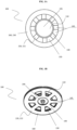
- Fig. 2A and 2B are top oblique and bottom oblique views, respectively, for the electrode array 200 according to the invention comprising four electrode segments 100 according to the invention.
- the electrode array 200 was made by cutting out a desired shape reminding the "four-leaf clover" of the mounting layer 220 along with the perforated area 145 comprising radially alternating void spaces 150 and solid spaces 140.
- the mounting layer 220 now comprises the X-shaped connecting area 280, such that the electrode segments 100 are connected by the connecting area 280, and are disposed such that each electrode segment 100 is situated equidistantly from an adjacent electrode segment 100.
- the connecting area 280 directly adjoins the surface-continuous area 160.
- the adhesive layer 230 having the surface-continuous area 160 of the electrode segments 100 shape along with the connecting area 280 shape is applied to the first side 221 of the mounting layer 220.
- the measuring electrodes 110 are positioned in the center of the perforated areas 145 of each electrode segment 100, such that the sensor element 195 of the measuring electrode 110 is provided on the first side 221 of the mounting layer 220 and the connector element 190 is on the other side 222 of the mounting layer 220, as shown in Fig. 2A and Fig. 2B .
- the electrode array 200 of the third embodiment is shown in Fig. 2A and Fig. 2B , and is the same as the electrode array 200 of the second embodiment, except that according to the third embodiment, connection wires (not shown) were electrically connected in parallel to the connector elements 190 in the form of a snap-fit element such as shown in Fig. 2B , such that each measuring electrode has a branch of the same electrical signal wire, which measures the same electric potential at each measuring electrode.
- FIG. 3 is a top view for the electrode array 200 according to the invention comprising two electrode segments 100 according to the invention.
- the electrode array 200 comprising the two electrode segments 100 was manufactured in the same way as the electrode array 200 of the second embodiment, except that the connecting area 280 that connects the two electrode segments 100 is rectangular in shape.
- the electrode array 200 of the fifth embodiment is shown in Fig. 3 , and is the same as the electrode array 200 of the fourth embodiment, except that according to the fifth embodiment, connection wires (not shown) were electrically connected in parallel to the connector elements 190 (not shown in Fig. 3 ) in the form of a snap-fit element, such that each measuring electrode has a branch of the same electrical signal wire, which measures the same electric potential at each measuring electrode.
- FIG. 4A is a top view for the electrode array 200 according to the invention comprising three electrode segments 100 according to the invention.
- the electrode array 200 comprising the three electrode segments 100 was manufactured in the same way as the electrode array 200 of the second embodiment, except that the connecting area 280 that connects the three electrode segments 100 is "T" - shaped.
- the electrode array 200 of the seventh embodiment is shown in Fig. 4A , and is the same as the electrode array 200 of the sixth embodiment, except that according to the seventh embodiment, connection wires (not shown) were electrically connected in parallel to the connector elements 190 (not shown in Fig. 4A ) in the form of a snap-fit element, such that each measuring electrode has a branch of the same electrical signal wire, which measures the same electric potential at each measuring electrode.
- FIG. 4B is a top view for the electrode array 200 according to the invention comprising three electrode segments 100 according to the invention.
- the electrode array 200 comprising the three electrode segments 100 was manufactured in the same way as the electrode array 200 of the second embodiment, except that the connecting area 280 that connects the three electrode segments 100 is triangular in shape.
- the electrode array 200 of the ninth embodiment is shown in Fig. 4B , and is the same as the electrode array 200 of the eighth embodiment, except that according to the ninth embodiment, connection wires (not shown) were electrically connected in parallel to the connector elements 190 (not shown in Fig. 4B ) in the form of a snap-fit element, such that each measuring electrode has a branch of the same electrical signal wire, which measures the same electric potential at each measuring electrode.
Landscapes
- Health & Medical Sciences (AREA)
- Life Sciences & Earth Sciences (AREA)
- Heart & Thoracic Surgery (AREA)
- Medical Informatics (AREA)
- Biophysics (AREA)
- Pathology (AREA)
- Engineering & Computer Science (AREA)
- Biomedical Technology (AREA)
- Veterinary Medicine (AREA)
- Physics & Mathematics (AREA)
- Molecular Biology (AREA)
- Surgery (AREA)
- Animal Behavior & Ethology (AREA)
- General Health & Medical Sciences (AREA)
- Public Health (AREA)
- Cardiology (AREA)
- Measurement And Recording Of Electrical Phenomena And Electrical Characteristics Of The Living Body (AREA)
Claims (14)
- Ein Elektrodensegment (100) für elektrokardiographische und/oder Bioimpedanzmessungen, umfassend eine Messelektrode (110), die ein Verbindungselement (190) zum Anschließen eines elektrischen Signalkabels und ein Sensorelement (195) zum Erfassen von Messsignalen vom Körper des Patienten umfasst, wobei die Messelektrode (110) in einer Montageschicht (220) angeordnet ist, die mit einer Klebeschicht (230) bedeckt ist, wobei die in der Montageschicht (220) angeordnete Messelektrode (110) von einem perforierten Bereich (145) umgeben ist, der frei von der Klebeschicht (230) ist, und der perforierte Bereich (145) wiederum von einem oberflächenkontinuierlichen Bereich (160) umgeben ist, der mit der Klebeschicht (230) bedeckt ist, wobei der perforierte Bereich (145) radial angeordnete abwechselnde Hohlräume (150) und feste Räume (140) umfasst.
- Elektrodensegment (100) nach Anspruch 1, wobei die Messelektrode (110) im Wesentlichen mittig im perforierten Bereich (145) angeordnet ist.
- Elektrodensegment (100) nach Anspruch 1 oder 2, wobei der perforierte Bereich (145) im Wesentlichen rund geformt ist.
- Elektrodensegment (100) nach Anspruch 1, wobei die festen Räume (140) und die Hohlräume (150) länglich geformt sind und radial von der Messelektrode (110) zum oberflächenkontinuierlichen Bereich (160) angeordnet sind.
- Elektrodensegment (100) nach einem der vorhergehenden Ansprüche, wobei der oberflächenkontinuierliche Bereich (160), der mit der Klebstoffschicht (230) bedeckt ist, im Wesentlichen ringförmig geformt ist.
- Elektrodensegment (100) nach einem der vorhergehenden Ansprüche, wobei die Befestigungsschicht (220) und die Klebeschicht (230) flexible Schichten sind, die so konfiguriert sind, dass sie ihre Form an die Form des Substrats anpassen, an dem sie angebracht werden.
- Elektrodensegment (100) nach einem der vorhergehenden Ansprüche, wobei die Dicke der Klebeschicht (230) kleiner als die Dicke des Sensorelements (195) der Messelektrode (110) ist.
- Elektrodensegment (100) nach einem der vorhergehenden Ansprüche, wobei das Verbindungselement (190) eine Schnappfassung für das elektrische Signalkabel ist.
- Elektrodenanordnung (200) für elektrokardiographische und/oder Bioimpedanzmessungen, wobei die Anordnung mindestens zwei Elektrodensegmente (100) nach den Ansprüchen 1 bis 8 umfasst und die Elektrodensegmente (100) durch einen Verbindungsbereich (280) miteinander verbunden sind, der an die jeweiligen Elektrodensegmente (100) angrenzt.
- Elektrodenanordnung (200) nach Anspruch 9, wobei der Verbindungsbereich (280) mit dem flächenkontinuierlichen Bereich (160) des Elektrodensegments (100) eine gleichmäßige Schicht bildet und mit der Klebeschicht (230) bedeckt ist.
- Elektrodenanordnung (200) nach Anspruch 9 oder 10, wobei der Verbindungsbereich (280) im Wesentlichen zentral angeordnet und von den Elektrodensegmenten (100) umgeben ist.
- Elektrodenanordnung (200) nach einem der Ansprüche 9 bis 11, wobei die durch den Verbindungsbereich (280) verbundenen Elektrodensegmente (100) so angeordnet sind, dass jedes Elektrodensegment (100) im Wesentlichen gleich weit vom benachbarten Elektrodensegment (100) entfernt angeordnet ist.
- Elektrodenanordnung (200) nach einem der Ansprüche 9 bis 12, wobei sie eine mehrsegmentige Konfiguration mit freier Biegung der einzelnen Elektrodensegmente (100) aufweist, die so konfiguriert sind, dass sie ihre Form an die Form des Substrats anpassen, an das sie geklebt werden.
- Elektrodenanordnung (200) nach einem der Ansprüche 9 bis 13, wobei die Verbindungselemente (190) der Messelektrode (110) elektrisch parallel geschaltet sind, so dass jede Messelektrode (110) einen Zweig desselben elektrischen Signaldrahts aufweist, der an jeder Messelektrode (110) dasselbe elektrische Potenzial misst.
Priority Applications (2)
| Application Number | Priority Date | Filing Date | Title |
|---|---|---|---|
| EP21461563.5A EP4111972B1 (de) | 2021-06-30 | 2021-06-30 | Elektrodensegment und elektrodenmatrix für elektrokardiographische und/oder bioimpedanzmessungen |
| PL21461563.5T PL4111972T3 (pl) | 2021-06-30 | 2021-06-30 | Segment elektrodowy oraz macierz elektrodowa do pomiarów elektrokardiograficznych i/lub bioimpedancyjnych |
Applications Claiming Priority (1)
| Application Number | Priority Date | Filing Date | Title |
|---|---|---|---|
| EP21461563.5A EP4111972B1 (de) | 2021-06-30 | 2021-06-30 | Elektrodensegment und elektrodenmatrix für elektrokardiographische und/oder bioimpedanzmessungen |
Publications (3)
| Publication Number | Publication Date |
|---|---|
| EP4111972A1 EP4111972A1 (de) | 2023-01-04 |
| EP4111972B1 true EP4111972B1 (de) | 2025-01-22 |
| EP4111972C0 EP4111972C0 (de) | 2025-01-22 |
Family
ID=77431270
Family Applications (1)
| Application Number | Title | Priority Date | Filing Date |
|---|---|---|---|
| EP21461563.5A Active EP4111972B1 (de) | 2021-06-30 | 2021-06-30 | Elektrodensegment und elektrodenmatrix für elektrokardiographische und/oder bioimpedanzmessungen |
Country Status (2)
| Country | Link |
|---|---|
| EP (1) | EP4111972B1 (de) |
| PL (1) | PL4111972T3 (de) |
Families Citing this family (2)
| Publication number | Priority date | Publication date | Assignee | Title |
|---|---|---|---|---|
| WO2022125706A1 (en) | 2020-12-09 | 2022-06-16 | Chen Guangren | Disposable ecg electrode to prevent shedding and tearing |
| DE102023104394A1 (de) * | 2023-02-23 | 2024-08-29 | pheal GmbH | Langzeit-körpertragbares EKG-Elektroden Plaster mitHydrogel-Speicher |
Family Cites Families (6)
| Publication number | Priority date | Publication date | Assignee | Title |
|---|---|---|---|---|
| US6129666A (en) * | 1997-04-04 | 2000-10-10 | Altec, Inc. | Biomedical electrode |
| US6602201B1 (en) * | 2000-07-10 | 2003-08-05 | Cardiodynamics International Corporation | Apparatus and method for determining cardiac output in a living subject |
| GB2527031A (en) | 2014-05-20 | 2015-12-16 | Sle Ltd | Electrode array with perforated backing |
| GB201706354D0 (en) | 2017-04-21 | 2017-06-07 | Surepulse Medical Ltd | Electrocardiogram sensor |
| AU2017279796A1 (en) * | 2017-12-22 | 2019-07-11 | Ti2 Medical Pty Ltd | Anisotropically conductive material for use with a biological surface |
| US20210113109A1 (en) * | 2019-10-22 | 2021-04-22 | Medicomp, Inc. | Silicon encapsulated heart monitoring device |
-
2021
- 2021-06-30 PL PL21461563.5T patent/PL4111972T3/pl unknown
- 2021-06-30 EP EP21461563.5A patent/EP4111972B1/de active Active
Also Published As
| Publication number | Publication date |
|---|---|
| EP4111972A1 (de) | 2023-01-04 |
| EP4111972C0 (de) | 2025-01-22 |
| PL4111972T3 (pl) | 2025-04-28 |
Similar Documents
| Publication | Publication Date | Title |
|---|---|---|
| JP5033466B2 (ja) | 放射状電極アレイ | |
| EP2328474B1 (de) | Pflaster und sensor-anordnung zur verwendung in systemen zur lokalisierung von medizinprodukten und in mapping-systemen | |
| US9655561B2 (en) | Multi-layered sensor apparatus | |
| US5833622A (en) | Non-invasive fetal probe having improved mechanical and electrical properties | |
| KR101538426B1 (ko) | 신체의 전기 신호를 측정하기 위한 전극 패치 및 이를 이용한 생체신호 측정 장치 | |
| JP2002502655A (ja) | 汎用心電図センサ位置決め装置および方法 | |
| AU2009271362A1 (en) | Crystalline form of (2s)-(-)-N-(6-chloro-2,3-dihydro-benzo[1,4]dioxin-2-ylmethyl)-sulfamide | |
| EP4111972B1 (de) | Elektrodensegment und elektrodenmatrix für elektrokardiographische und/oder bioimpedanzmessungen | |
| CN110573070B (zh) | 生物传感器用片材 | |
| CN113301848A (zh) | 弹性可穿戴传感器 | |
| CN215227731U (zh) | 一种易穿戴的心电导联线及心电图机 | |
| CN118766468A (zh) | 生物电信号采集器、穿戴式生理监测装置及生理监测系统 | |
| JP4855734B2 (ja) | 心電図測定用電極及び心電図測定装置 | |
| US11278243B2 (en) | Repositionable surface electrodes | |
| US7164939B2 (en) | Disposable biomedical electrode having multiple connection sites | |
| CN110545718A (zh) | 生物传感器 | |
| CN110621220A (zh) | 利用粘合剂微结构的健康贴片 | |
| CN110621218A (zh) | 利用粘性微结构的无线心脏监测系统 | |
| HK40057773A (en) | Elastic wearable sensor |
Legal Events
| Date | Code | Title | Description |
|---|---|---|---|
| PUAI | Public reference made under article 153(3) epc to a published international application that has entered the european phase |
Free format text: ORIGINAL CODE: 0009012 |
|
| STAA | Information on the status of an ep patent application or granted ep patent |
Free format text: STATUS: THE APPLICATION HAS BEEN PUBLISHED |
|
| AK | Designated contracting states |
Kind code of ref document: A1 Designated state(s): AL AT BE BG CH CY CZ DE DK EE ES FI FR GB GR HR HU IE IS IT LI LT LU LV MC MK MT NL NO PL PT RO RS SE SI SK SM TR |
|
| STAA | Information on the status of an ep patent application or granted ep patent |
Free format text: STATUS: REQUEST FOR EXAMINATION WAS MADE |
|
| 17P | Request for examination filed |
Effective date: 20230310 |
|
| RBV | Designated contracting states (corrected) |
Designated state(s): AL AT BE BG CH CY CZ DE DK EE ES FI FR GB GR HR HU IE IS IT LI LT LU LV MC MK MT NL NO PL PT RO RS SE SI SK SM TR |
|
| STAA | Information on the status of an ep patent application or granted ep patent |
Free format text: STATUS: EXAMINATION IS IN PROGRESS |
|
| 17Q | First examination report despatched |
Effective date: 20240703 |
|
| GRAP | Despatch of communication of intention to grant a patent |
Free format text: ORIGINAL CODE: EPIDOSNIGR1 |
|
| STAA | Information on the status of an ep patent application or granted ep patent |
Free format text: STATUS: GRANT OF PATENT IS INTENDED |
|
| GRAS | Grant fee paid |
Free format text: ORIGINAL CODE: EPIDOSNIGR3 |
|
| INTG | Intention to grant announced |
Effective date: 20241119 |
|
| RIN1 | Information on inventor provided before grant (corrected) |
Inventor name: MURAWSKI, PIOTR Inventor name: KRZESINSKI, PAWEL Inventor name: BACZYK, PIOTR Inventor name: MARCINIAK, PIOTR Inventor name: WALCZAK, ANDRZEJ |
|
| GRAA | (expected) grant |
Free format text: ORIGINAL CODE: 0009210 |
|
| STAA | Information on the status of an ep patent application or granted ep patent |
Free format text: STATUS: THE PATENT HAS BEEN GRANTED |
|
| AK | Designated contracting states |
Kind code of ref document: B1 Designated state(s): AL AT BE BG CH CY CZ DE DK EE ES FI FR GB GR HR HU IE IS IT LI LT LU LV MC MK MT NL NO PL PT RO RS SE SI SK SM TR |
|
| REG | Reference to a national code |
Ref country code: GB Ref legal event code: FG4D |
|
| REG | Reference to a national code |
Ref country code: CH Ref legal event code: EP |
|
| REG | Reference to a national code |
Ref country code: IE Ref legal event code: FG4D |
|
| REG | Reference to a national code |
Ref country code: DE Ref legal event code: R096 Ref document number: 602021025125 Country of ref document: DE |
|
| U01 | Request for unitary effect filed |
Effective date: 20250209 |
|
| U07 | Unitary effect registered |
Designated state(s): AT BE BG DE DK EE FI FR IT LT LU LV MT NL PT RO SE SI Effective date: 20250213 |
|
| RAP4 | Party data changed (patent owner data changed or rights of a patent transferred) |
Owner name: WOJSKOWY INSTYTUT MEDYCZNY - PANSTWOWYINSTYTUT BADAWCZY Owner name: WOJSKOWA AKADEMIA TECHNICZNA |
|
| U1H | Name or address of the proprietor changed after the registration of the unitary effect |
Owner name: WOJSKOWY INSTYTUT MEDYCZNY - PANSTWOWYINSTYTUT BADAWCZY; PL Owner name: WOJSKOWA AKADEMIA TECHNICZNA; PL |
|
| U20 | Renewal fee for the european patent with unitary effect paid |
Year of fee payment: 5 Effective date: 20250411 |
|
| PG25 | Lapsed in a contracting state [announced via postgrant information from national office to epo] |
Ref country code: RS Free format text: LAPSE BECAUSE OF FAILURE TO SUBMIT A TRANSLATION OF THE DESCRIPTION OR TO PAY THE FEE WITHIN THE PRESCRIBED TIME-LIMIT Effective date: 20250422 |
|
| PGFP | Annual fee paid to national office [announced via postgrant information from national office to epo] |
Ref country code: PL Payment date: 20250515 Year of fee payment: 5 |
|
| PG25 | Lapsed in a contracting state [announced via postgrant information from national office to epo] |
Ref country code: ES Free format text: LAPSE BECAUSE OF FAILURE TO SUBMIT A TRANSLATION OF THE DESCRIPTION OR TO PAY THE FEE WITHIN THE PRESCRIBED TIME-LIMIT Effective date: 20250122 |
|
| PG25 | Lapsed in a contracting state [announced via postgrant information from national office to epo] |
Ref country code: IS Free format text: LAPSE BECAUSE OF FAILURE TO SUBMIT A TRANSLATION OF THE DESCRIPTION OR TO PAY THE FEE WITHIN THE PRESCRIBED TIME-LIMIT Effective date: 20250522 Ref country code: NO Free format text: LAPSE BECAUSE OF FAILURE TO SUBMIT A TRANSLATION OF THE DESCRIPTION OR TO PAY THE FEE WITHIN THE PRESCRIBED TIME-LIMIT Effective date: 20250422 |
|
| PG25 | Lapsed in a contracting state [announced via postgrant information from national office to epo] |
Ref country code: HR Free format text: LAPSE BECAUSE OF FAILURE TO SUBMIT A TRANSLATION OF THE DESCRIPTION OR TO PAY THE FEE WITHIN THE PRESCRIBED TIME-LIMIT Effective date: 20250122 |
|
| PG25 | Lapsed in a contracting state [announced via postgrant information from national office to epo] |
Ref country code: GR Free format text: LAPSE BECAUSE OF FAILURE TO SUBMIT A TRANSLATION OF THE DESCRIPTION OR TO PAY THE FEE WITHIN THE PRESCRIBED TIME-LIMIT Effective date: 20250423 |
|
| PG25 | Lapsed in a contracting state [announced via postgrant information from national office to epo] |
Ref country code: SM Free format text: LAPSE BECAUSE OF FAILURE TO SUBMIT A TRANSLATION OF THE DESCRIPTION OR TO PAY THE FEE WITHIN THE PRESCRIBED TIME-LIMIT Effective date: 20250122 |
|
| PG25 | Lapsed in a contracting state [announced via postgrant information from national office to epo] |
Ref country code: CZ Free format text: LAPSE BECAUSE OF FAILURE TO SUBMIT A TRANSLATION OF THE DESCRIPTION OR TO PAY THE FEE WITHIN THE PRESCRIBED TIME-LIMIT Effective date: 20250122 |
|
| PG25 | Lapsed in a contracting state [announced via postgrant information from national office to epo] |
Ref country code: SK Free format text: LAPSE BECAUSE OF FAILURE TO SUBMIT A TRANSLATION OF THE DESCRIPTION OR TO PAY THE FEE WITHIN THE PRESCRIBED TIME-LIMIT Effective date: 20250122 |
|
| PLBE | No opposition filed within time limit |
Free format text: ORIGINAL CODE: 0009261 |
|
| STAA | Information on the status of an ep patent application or granted ep patent |
Free format text: STATUS: NO OPPOSITION FILED WITHIN TIME LIMIT |
|
| REG | Reference to a national code |
Ref country code: CH Ref legal event code: L10 Free format text: ST27 STATUS EVENT CODE: U-0-0-L10-L00 (AS PROVIDED BY THE NATIONAL OFFICE) Effective date: 20251203 |
|
| 26N | No opposition filed |
Effective date: 20251023 |
|
| REG | Reference to a national code |
Ref country code: CH Ref legal event code: H13 Free format text: ST27 STATUS EVENT CODE: U-0-0-H10-H13 (AS PROVIDED BY THE NATIONAL OFFICE) Effective date: 20260127 |
|
| PG25 | Lapsed in a contracting state [announced via postgrant information from national office to epo] |
Ref country code: MC Free format text: LAPSE BECAUSE OF FAILURE TO SUBMIT A TRANSLATION OF THE DESCRIPTION OR TO PAY THE FEE WITHIN THE PRESCRIBED TIME-LIMIT Effective date: 20250122 |
|
| GBPC | Gb: european patent ceased through non-payment of renewal fee |
Effective date: 20250630 |