EP4111118B1 - Vorrichtung und verfahren zum brennen und/oder kalzinieren von stückigem gut - Google Patents
Vorrichtung und verfahren zum brennen und/oder kalzinieren von stückigem gut Download PDFInfo
- Publication number
- EP4111118B1 EP4111118B1 EP21705954.2A EP21705954A EP4111118B1 EP 4111118 B1 EP4111118 B1 EP 4111118B1 EP 21705954 A EP21705954 A EP 21705954A EP 4111118 B1 EP4111118 B1 EP 4111118B1
- Authority
- EP
- European Patent Office
- Prior art keywords
- cooling
- zone
- shaft
- exhaust gas
- shaft furnace
- Prior art date
- Legal status (The legal status is an assumption and is not a legal conclusion. Google has not performed a legal analysis and makes no representation as to the accuracy of the status listed.)
- Active
Links
Images


Classifications
-
- F—MECHANICAL ENGINEERING; LIGHTING; HEATING; WEAPONS; BLASTING
- F27—FURNACES; KILNS; OVENS; RETORTS
- F27B—FURNACES, KILNS, OVENS OR RETORTS IN GENERAL; OPEN SINTERING OR LIKE APPARATUS
- F27B1/00—Shaft or like vertical or substantially vertical furnaces
- F27B1/10—Details, accessories or equipment specially adapted for furnaces of these types
- F27B1/24—Cooling arrangements
-
- F—MECHANICAL ENGINEERING; LIGHTING; HEATING; WEAPONS; BLASTING
- F27—FURNACES; KILNS; OVENS; RETORTS
- F27D—DETAILS OR ACCESSORIES OF FURNACES, KILNS, OVENS OR RETORTS, IN SO FAR AS THEY ARE OF KINDS OCCURRING IN MORE THAN ONE KIND OF FURNACE
- F27D17/00—Arrangements for using waste heat; Arrangements for using, or disposing of, waste gases
- F27D17/10—Arrangements for using waste heat
-
- F—MECHANICAL ENGINEERING; LIGHTING; HEATING; WEAPONS; BLASTING
- F27—FURNACES; KILNS; OVENS; RETORTS
- F27D—DETAILS OR ACCESSORIES OF FURNACES, KILNS, OVENS OR RETORTS, IN SO FAR AS THEY ARE OF KINDS OCCURRING IN MORE THAN ONE KIND OF FURNACE
- F27D19/00—Arrangements of controlling devices
-
- F—MECHANICAL ENGINEERING; LIGHTING; HEATING; WEAPONS; BLASTING
- F27—FURNACES; KILNS; OVENS; RETORTS
- F27D—DETAILS OR ACCESSORIES OF FURNACES, KILNS, OVENS OR RETORTS, IN SO FAR AS THEY ARE OF KINDS OCCURRING IN MORE THAN ONE KIND OF FURNACE
- F27D99/00—Subject matter not provided for in other groups of this subclass
- F27D99/0001—Heating elements or systems
- F27D99/0033—Heating elements or systems using burners
-
- Y—GENERAL TAGGING OF NEW TECHNOLOGICAL DEVELOPMENTS; GENERAL TAGGING OF CROSS-SECTIONAL TECHNOLOGIES SPANNING OVER SEVERAL SECTIONS OF THE IPC; TECHNICAL SUBJECTS COVERED BY FORMER USPC CROSS-REFERENCE ART COLLECTIONS [XRACs] AND DIGESTS
- Y02—TECHNOLOGIES OR APPLICATIONS FOR MITIGATION OR ADAPTATION AGAINST CLIMATE CHANGE
- Y02P—CLIMATE CHANGE MITIGATION TECHNOLOGIES IN THE PRODUCTION OR PROCESSING OF GOODS
- Y02P40/00—Technologies relating to the processing of minerals
- Y02P40/40—Production or processing of lime, e.g. limestone regeneration of lime in pulp and sugar mills
Definitions
- the invention relates to a device and method for firing and/or calcining lumpy material, in particular limestone or other carbonates, with a shaft furnace which has at least one firing zone and one cooling zone.
- a shaft furnace for the continuous firing of mineral materials with a firing zone and a cooling zone is known, the hot gases of the firing zone and the cooling air for the firing material being removed via a suction space formed in the transition area between the firing and cooling zones.
- a method for firing material, in particular carbonate-containing material, in a shaft furnace with a shaft comprises, in one aspect, that the material passes through a material inlet into a preheating zone for preheating the material Firing zone for firing the material and a cooling zone for cooling the fired material flows to a material outlet, with cooling air being admitted into the cooling zone and the exhaust gas being exhausted from the shaft via an exhaust gas outlet. Cooling air is exhausted from the shaft via a cooling gas extraction device, the cooling gas extraction device extending from the cooling zone into the combustion zone and from the combustion zone out of the shaft. The exhaust gas released from the shaft via the exhaust gas outlet is at least partially directed into the combustion zone.
- the material to be burned is, for example, granular material, in particular limestone, with a grain size of 10 to 150 mm, preferably 30 to 100 mm, in particular 40 to 80 mm.
- the exhaust gas preferably has a CO 2 content of at least 30% to at least 90%, preferably at least 35% to at least 45%, preferably based on dry gas.
- the material inlet is arranged in particular at the upper end of the shaft.
- the preheating zone for preheating the material is arranged in the direction of flow of the material in front of the combustion zone.
- the preheating zone preferably connects directly to a material inlet of the material into the shaft furnace and serves to preheat the material to a temperature of approximately 600 ° C to 800 ° C.
- the firing zone preferably adjoins the preheating zone directly and serves to burn the material, which is preferably heated to a temperature of approximately 900 ° C to 1800 ° C.
- the cooling zone preferably adjoins the firing zone directly and serves to cool the fired material to a temperature of, for example, 100 ° C.
- the material outlet is arranged, for example, in an outlet funnel adjoining the cooling zone, the material outlet having, for example, a turntable or push tables for discharging material from the cooling zone into the outlet funnel.
- the cooling air is preferably blown into the cooling zone of the shaft furnace via a cooling air inlet.
- the cooling air inlet is preferably arranged in the shaft wall of the cooling zone.
- a plurality of burners are preferably arranged in the combustion zone of the shaft.
- the shaft in the Combustion zone has one or more combustion chamber levels in which combustion chambers are arranged, preferably circumferentially around the combustion zone and the cooling gas exhaust device.
- a burner is preferably arranged in each combustion chamber.
- the shaft does not have a combustion chamber but rather a plurality of side burners which extend through the shaft wall into the combustion zone.
- the side burners and/or the burners in the combustion chambers are preferably designed as burner lances and in particular tubular. They serve to direct fuel and preferably an oxidizing agent into the combustion zone.
- the shaft in the combustion zone has a plurality of combustion chambers and side burners.
- the exhaust gas outlet is preferably arranged in the upper region of the shaft, in particular in the preheating zone or in the upper region of the combustion zone
- the inlet of the cooling gas extraction device for admitting cooling air into the cooling gas extraction device is preferably arranged completely within the cooling zone.
- the inlet is arranged below the fuel lines, in particular the openings of the combustion chambers and/or the burner lances into the combustion zone.
- the cooling gas extraction device is preferably arranged at least partially below the exhaust gas outlet.
- the gas outlet of the cooling gas extraction device for discharging the gas into a cooling gas extraction line arranged outside the shaft is preferably arranged within the combustion zone or the preheating zone. Cooling air is preferably led out of the shaft together with exhaust gas from the combustion zone via the cooling air extraction line.
- the special design and arrangement of the cooling gas extraction device makes it possible to easily influence the cooling gas extraction.
- the atmosphere in the combustion zone is essentially separated from the atmosphere in the cooling zone only by the material located in the lowest part of the combustion zone.
- the cooling gas introduced into the combustion zone under excess pressure generally takes the path of least resistance.
- the amount of The gas to be withdrawn can be controlled very easily, so that, for example, the entire cooling gas is withdrawn via the cooling gas extraction device and does not reach the combustion zone via the material bed.
- the control element it is also possible for only a portion of the cooling gas to be withdrawn via the cooling gas extraction device and the rest to be fed to the cooling zone.
- the control element it is also fundamentally conceivable for the control element to be opened to such an extent that part of the exhaust gas is withdrawn from the combustion zone through the material bed into the cooling zone and from there via the cooling gas extraction device.
- the return of the exhaust gas released from the shaft via the exhaust gas outlet at least partially into the combustion zone enables the atmosphere in the combustion zone to be heated by means of the withdrawn CO2-containing exhaust gas.
- the exhaust gas is fed to a heat exchanger before being introduced into the combustion zone.
- the heat exchanger is, for example, a heat exchanger with water cooling.
- the exhaust gas is, for example, fed to a first and a second heat exchanger before being introduced into the combustion zone, the first heat exchanger serving to cool the exhaust gas using cooling water and the second heat exchanger serving to heat the exhaust gas using the gas removed via the cooling gas extraction device.
- the exhaust gas is preferably additionally dedusted using a filter. Following the first heat exchanger, the exhaust gas is preferably at least partially removed and preferably stored for further processing.
- the exhaust gas Before being introduced into the combustion zone, the exhaust gas is, for example, fed to just one heat exchanger, which is, for example, the heat exchanger for heating the exhaust gas by means of the gas removed via the cooling gas extraction device.
- the exhaust gas outlet line preferably points in front of the exhaust gas in the flow direction
- Heat exchanger in particular the heat exchanger for heating the exhaust gas by means of the gas removed via the cooling gas extraction device, a fan, in particular a high-pressure fan, a rotary piston compressor and / or a screw compressor.
- a heat exchanger operated by water cooling is, for example, arranged exclusively in a branch branched off from the exhaust gas outlet line for removing the exhaust gas from the system.
- the cooling gas extraction device is preferably connected to a cooling air extraction line for guiding the gas discharged from the shaft and the cooling air extraction line has a heat exchanger in the flow direction of the gas, preferably the second heat exchanger described above, a filter for dedusting the cooling exhaust air and / or a control element.
- the heat exchanger is preferably operated with the exhaust gas from the exhaust gas outlet line.
- a cooling gas such as air
- a direct current combustion zone is formed within the combustion zone.
- the gas preferably flows in the same direction as the material flow through the combustion zone of the shaft.
- a countercurrent combustion zone is preferably formed within the combustion zone. In the countercurrent combustion zone, the material preferably flows through the shaft against the gas flow.
- the countercurrent combustion zone forms in particular above the cocurrent combustion zone and preferably above the burners of the combustion zone.
- an overpressure is set within the shaft furnace.
- the excess pressure is, for example, approximately 300 mbar.
- cooling gas and an oxidizing agent, such as combustion air are preferably blown into the shaft furnace via one or more fans.
- an oxidizing agent in particular oxygen-rich gas, is passed into the combustion zone.
- the oxidizing agent is, for example, pure oxygen, air, oxygen-enriched air or a gas with an oxygen content of at least 90%.
- the oxidizing agent is preferably fed into the combustion zone via an oxidizing agent line.
- the oxidizing agent line is preferably at least partially designed as a ring line around the shaft.
- the oxidant line is an oxidant lance which extends into the combustion zone of the shaft furnace and has an outlet for discharging oxidant into the combustion zone.
- the oxidizing agent lance is attached to the burner lance or directly below the burner lance. It is also conceivable that the oxidizing agent lance runs through the burner lance.
- the burner lance is preferably designed in such a way that oxidizing agent flows through the burner lance together with combustion air and fuel.
- the oxidizing agent is mixed with the exhaust gas before entering the combustion zone.
- the shaft furnace preferably has a gas mixer into which the oxidizing agent and the exhaust gas are preferably fed in a controlled manner.
- the invention further comprises a shaft furnace for burning material, in particular carbonate-containing material, with a shaft having a material inlet in the flow direction of the material, a preheating zone for preheating the material, a combustion zone for burning the material with at least one fuel line for admitting fuel into the combustion zone, a A cooling zone having a cooling air inlet for cooling the fired material, and a material outlet for discharging the material from the shaft furnace, the shaft furnace having an exhaust gas outlet for discharging exhaust gas from the shaft.
- the shaft furnace has a cooling gas exhaust device for exhausting cooling air from the shaft, which extends from the cooling zone into the combustion zone and from the combustion zone out of the shaft. The exhaust gas outlet is used to return the exhaust gas to the combustion zone tied together.
- the cooling gas extraction device preferably extends centrally through the combustion zone. This enables uniform firing of the material present in the firing zone without the cooling gas exhaust device having a negative influence on the firing process.
- the cooling gas extraction device preferably extends over the entire length of the combustion zone.
- the cooling gas extraction device is, for example, a pipe or a shaft with a particularly circular or angular cross section.
- the combustion zone is preferably at least partially circular and arranged concentrically with the cooling gas exhaust device.
- the width of the circular ring is, for example, approximately 0.5m to 2m, preferably 1m.
- the combustion zone is completely or partially designed as a hollow cylinder, the interior of the hollow cylinder being formed by the cooling gas extraction device.
- the cooling gas extraction device is preferably closed, so that the cooling gas extraction device forms a material-free space during operation of the shaft furnace.
- the cooling gas extraction device is preferably connected to a control element for regulating the amount of gas that flows through the cooling gas extraction device.
- the control element is, for example, a valve or a flap. This enables a specific amount of cooling exhaust air to be removed in a targeted manner through the cooling gas extraction device, whereby, for example, the cooling air can be completely or partially withdrawn from the cooling zone.
- the cooling air is partially withdrawn from the cooling zone through the cooling gas extraction device, the remaining part of the cooling air flows into the combustion zone and is discharged from the shaft via the exhaust gas outlet line.
- the control element is preferably connected to a sensor which is designed to determine the pressure difference between the combustion zone and the cooling gas extraction device and is set up.
- the shaft furnace preferably has a further sensor for determining the oxygen content and/or the CO2 content in the exhaust gas outlet line and/or the cooling gas exhaust line.
- the control element is connected in particular via a control device to the sensor for determining the pressure difference and/or the oxygen content and/or the CO2 content.
- the control device is designed in such a way that it controls the control element depending on the determined or desired pressure difference, the oxygen content and/or the CO2 content.
- the control element can be moved from an open position, in which the cooling gas exhaust line is hardly or not at all narrowed by the control element, into a closed position, in which no gas can flow through the cooling gas exhaust line.
- the control device preferably controls the movement of the control element continuously between the closed and the open position.
- the sensors are preferably connected to the control device in such a way that the determined pressure difference, oxygen content and CO2 content are transmitted to the control device.
- At least one combustion chamber level is formed in the combustion zone, in which at least one combustion chamber with a burner is arranged and at least one additional burner, preferably a side burner, such as a burner lance, is arranged in the combustion zone.
- combustion chamber levels are formed, with at least one combustion chamber being arranged in each combustion chamber level.
- a burner is preferably mounted in each combustion chamber of the combustion chamber levels.
- the burner is, for example, a burner lance that extends essentially horizontally into the combustion chamber.
- at least one additional burner in particular in a side burner designed as a burner lance, is mounted in the combustion chamber plane between two adjacent combustion chambers.
- the additional burners are, for example, slidably mounted within the shaft wall so that the insertion depth can be varied.
- the additional burners are preferred installed completely outside the combustion chambers within the combustion zone.
- the combustion zone for example, has no combustion chambers but only side burners, preferably designed as burner lances.
- the combustion zone preferably has one or more, in particular two, burner levels, in each of which a plurality of side burners, in particular burner lances, for example of different insertion depths, are arranged.
- the burner lances are preferably attached to the inner wall of the combustion zone and arranged evenly spaced apart from one another. In particular, the burner lances are arranged at the lower end region of the combustion zone.
- the exhaust gas outlet line is connected to the oxidizer line, so that the exhaust gas is introduced into the combustion zone together with the oxidizer.
- the fuel line is connected, for example, to a plurality of burners, in particular burner lances, which extend into the combustion zone and the burner lances are arranged at at least two different height levels within the combustion zone.
- a heat exchanger is arranged between the exhaust gas outlet and the combustion zone, in particular the oxidizing agent line.
- a first heat exchanger for cooling the exhaust gas for example with water
- a second heat exchanger for heating the exhaust gas with the gas withdrawn via the cooling gas extraction device are arranged downstream of the exhaust gas outlet, preferably in countercurrent.
- a filter for example, is arranged downstream of the exhaust gas outlet, in particular between the heat exchangers, for removing dust from the exhaust gas.
- a cocurrent combustion zone and preferably a countercurrent combustion zone are formed within the combustion zone.
- the cooling air inlet is connected to a compressor for generating an overpressure in the shaft furnace.
- the material inlet and/or the material outlet each have a lock for letting in and/or letting out material into the shaft furnace.
- One Lock or a material inlet designed as a lock is preferably designed in such a way that only the raw material to be burned gets into the shaft, but not the ambient air.
- the lock is preferably designed in such a way that it seals the shaft airtight from the environment and allows solids, such as the material to be burned, to enter the shaft.
- the shaft furnace has an oxidizing agent line for conveying oxidizing agent, in particular oxygen-rich gas, into the combustion zone.
- the oxidizing agent line is preferably designed as a ring line that extends around the outside of the shaft.
- the exhaust gas outlet is connected to the oxidant line for guiding the exhaust gas via the oxidant line into the combustion zone.
- the shaft furnace preferably has a gas mixer connected to the oxidizer line and the exhaust gas outlet so that the exhaust gas is mixed with the oxidizer in the gas mixer.
- the cooling gas extraction device has a plurality of gas outlets for exhausting the gas withdrawn from the shaft from the shaft.
- the cooling gas extraction device is connected to four, in particular one to ten, gas outlets.
- the gas outlets are preferably arranged in a star shape relative to one another around the cooling gas extraction device and, in particular, are evenly spaced apart from one another.
- each gas outlet is connected to a respective heat exchanger for cooling the gas withdrawn via the cooling gas extraction device in countercurrent with the exhaust gas.
- the number of heat exchangers downstream of the cooling gas extraction device corresponds to the number of gas outlets.
- At least one combustion chamber level is formed in the combustion zone, in which at least one combustion chamber with a burner is arranged and at least one additional burner in the combustion zone, preferably a side burner is arranged.
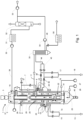
- a shaft furnace 1 for firing granular material
- the shaft furnace 1 comprising a shaft 2, which preferably extends in the vertical direction and, for example, has a substantially constant cross section.
- the shaft 2 has a round, in particular circular, or angular, in particular square cross section.
- the shaft 2 is surrounded by a shaft wall, which is made, for example, of steel with an adjoining brick, fireproof inner wall.
- the shaft 2 has at its upper end a material inlet 3, which is designed, for example, as an upper opening of the shaft 2 and in particular as a lock 3 and preferably extends over the entire or part of the cross section of the shaft 2.
- the material inlet 3 serves to admit material to be burned into the shaft furnace 1.
- a material inlet designed as a lock 3 is preferably designed in such a way that only the raw material to be burned enters the shaft 2, but not the ambient air.
- the lock 3 is preferably designed in such a way that it seals the shaft 2 airtight from the environment and allows solids, such as the material to be burned, to enter the shaft.
- the shaft 2 has an exhaust gas outlet 19 in an upper area for discharging furnace exhaust gas from the shaft 2.
- the exhaust gas is led from the exhaust gas outlet 19 into an exhaust gas outlet line 39.
- the exhaust gas is extracted via a material-free annular gap 37.
- the shaft 2 Within the shaft 2, the material to be burned is conveyed from top to bottom through the shaft 2 due to gravity, the shaft 2 having a preheating zone 21 in the conveying direction of the material for preheating the material, a combustion zone 20 for firing the material and a cooling zone 22 for cooling the fired material.
- the preheating zone 21 preferably extends from the material inlet 3 to the combustion zone 20 and serves for preheating of the material before firing.
- the material is burned, in particular calcined, preferably by deacidification, in the firing zone 20.
- Combustion chamber levels 8, 9 are preferably formed in the combustion zone 20 of the shaft 2, with at least one combustion chamber 4, 5 being arranged in each combustion chamber level 8, 9.
- Fig. 1 For example, two combustion chamber levels 8, 9 are arranged in the shaft 2. It is also conceivable that there is only one combustion chamber level 8, 9 or more than two combustion chamber levels.
- the combustion chamber levels 8, 9 are in detail with reference to Figs. 2 and 3 described.
- a burner 10 is mounted in each combustion chamber 4, 5 of the combustion chamber levels 8, 9.
- the burner 10 is, for example, a burner lance that extends essentially horizontally into the combustion chamber 4, 5.
- the shaft furnace 1 further has a fuel line 13 for introducing fuel and an oxidizing agent supply line 16 for introducing an oxidizing agent into the combustion zone 20 of the shaft 2.
- the fuel line 13, for example, branches into two fuel ring lines 14, 15, each of which extends around the circumference of the shaft wall, with an upper fuel ring line 14 with the burner 10 of the upper combustion chamber level 8 and a lower fuel ring line 15 with the burner 10 of the lower combustion chamber level 9 connected to the supply of fuel.
- the fuel line 13 is preferably connected to each of the fuel ring lines 14, 15 via a valve, so that the fuel supply can be supplied in a controlled manner.
- the fuel ring lines 14, 15 are at least partially designed as ring lines and, for example, partially as a supply line to the ring line.
- the oxidant supply line 16 for example, branches into two oxidant ring lines 17, 18, each of which extends around the circumference of the shaft wall, with an upper oxidant ring line 17 with the burner 10 of the upper combustion chamber level 8 and a lower oxidant ring line 18 with the burner 10 of the lower combustion chamber level 9 is connected to the supply of oxidizing agent.
- the oxidant supply lines 16 is preferred each connected to each of the oxidizing agent ring lines 17, 18 via a valve, so that the oxidizing agent can be supplied in a controlled manner.
- the oxidizing agent ring lines 17, 18 are at least partially designed as ring lines and, for example, partially as a supply line to the ring line.
- the oxidizing agent is, for example, air, air enriched with oxygen, pure oxygen or a gas with an oxygen content of approximately at least 90%.
- the oxidizing agent supply line 16 and the fuel line 13 are each connected, for example, to a fan, preferably a compressor, so that the oxidizing agent and/or the fuel is acted upon in the direction of the burner 10.
- a material outlet 40 for discharging the burned material.
- the material outlet is, for example, a lock as described with reference to the material inlet 3.
- the cooling zone 22 is adjoined in the material conveying direction by an outlet funnel 25, in particular a lower material bunker, which opens into the material outlet 40 for discharging the material from the shaft furnace 1.
- a discharge device 41 is arranged, which serves to discharge material from the cooling zone 22 of the shaft furnace 1 into the outlet funnel 25.
- the discharge device 41 is, for example, a turntable or push tables.
- the shaft 12 further has a cooling gas extraction device 29 for removing at least part of the cooling air from the shaft 2.
- the cooling gas extraction device 29 is, for example, concentric with the shaft 2 and within it arranged inner cylinder is formed.
- the cooling air flows through the shaft furnace 1, in particular the shaft 2, from bottom to top in the vertical direction and in countercurrent to the material and leaves the shaft 2 through the exhaust gas outlet line 39 of the exhaust gas outlet 19 and/or through the cooling gas extraction device 29.
- the cooling gas extraction device 29 extends For example, in the middle through the combustion zone 20 of the shaft 2.
- the combustion zone 20 of the shaft 2 is preferably at least partially or completely designed as an annular space which is arranged concentrically to the cooling gas extraction device 29.
- the cooling gas extraction device 29 extends from the cooling zone 22 or the boundary between the combustion zone 20 and the cooling zone 22 through the combustion zone 20, for example into the preheating zone 21 and through the shaft wall out of the shaft 2.
- the cooling gas extraction device 29 is provided with a gas outlet 12 for exhausting the cooling air and, for example, exhaust gas from the shaft 2.
- the gas emerging from the gas outlet 12 preferably flows into a cooling air extraction line 11.
- the cooling gas extraction device 29 extends through the shaft 2, for example up to or beyond the gas outlet this beyond.
- the gas outlet 12 is preferably arranged at the height of the combustion zone 22.
- the cooling gas exhaust device 29 preferably has a circular cross section and is closed at the top so that no material to be burned gets into it Cooling gas extraction device 29 occurs.
- the combustion zone 20 in particular has a circular cross-section, the width of the circular ring being approximately 0.5 to 2 m, preferably approximately 1 m.
- the shaft furnace 1 optionally also has an upper inner cylinder 6, which extends at least partially through the preheating zone 21 and is arranged above the cooling gas extraction device 29.
- the upper inner cylinder 6 has an outlet for discharging gas from the shaft 2, this outlet preferably being closed so that the gas entering the upper inner cylinder 6 cannot escape from the shaft 2.
- the upper inner cylinder 6 serves to equalize the material flow within the preheating zone 21.
- a cooling air inlet for cooling the upper inner cylinder 6 is preferably arranged in the preheating zone 21. Cooling air accelerated preferably by means of a fan 28 flows through the cooling air inlet into a ring line arranged around the preheating zone 21 and/or a cooling air line 7 located at least partially within the upper inner cylinder 6.
- a countercurrent combustion zone 23 is formed within the combustion zone 20, in which the material flows through the shaft 2 against the gas flow.
- the countercurrent combustion zone 23 is formed, for example, above the lower combustion chamber level 9.
- a cocurrent combustion zone 24 is additionally formed within the combustion zone 20, in which the gas flow runs in the same direction as the material flow through the shaft 2.
- the direct current combustion zone 24 is, for example, formed below the lower combustion chamber level 9.
- the height of the shaft 2 is preferably determined by the process
- the residence times of the fuel material are determined. These residence times are distributed over the upper preheating zone 21, which adjoins the material inlet 3, on the combustion zone 20 that follows downwards, and the cooling zone 22, which extends at least as far as the discharge device 41.
- the material is heated to a temperature of up to approximately 800 ° C, with the combustion zone 22, for example, having a temperature of 800 ° C to 1800 ° C and in the cooling zone 22 the material is cooled again to approximately 100 ° C.
- a material column is formed in the combustion zone 20 of the shaft 2 with the material supplied via the material feed 3, the material moving downwards due to gravity and in the area of the cooling zone 22 via the material outlet 40 as a calcined product, for example quicklime , is deducted.
- the material fills the combustion zone 20 preferably over the entire preferably circular cross section and the cooling zone 22.
- the cooling gas extraction device 29 is preferably free of material. The cooling gas flows through the material bed and reaches the cooling gas extraction device 29. At least some of the exhaust gas from the combustion zone 24 preferably reaches the cooling gas extraction device 29 in addition to the cooling gas.
- the cooling gas extraction device 29 is connected via the cooling air extraction line 11 to a control element 46 in the form of, for example, a flap for regulating the amount of air that flows through the cooling gas extraction device 29, in particular the cooling air extraction line 11 adjoining it.
- the exhaust gas outlet 19 for discharging the exhaust gas from the preheating zone 21 is preferably connected via the exhaust gas outlet line 39 to an exhaust gas filter 31 for dedusting the exhaust gas and optionally to a cooling device 32, in particular a heat exchanger, for cooling the hot exhaust gas.
- the exhaust gas from the combustion zone 20 is at least partially or completely removed from the shaft 2 via the exhaust gas outlet line 39. That via the exhaust outlet 19 and the The exhaust gas withdrawn from the shaft 2 in the exhaust gas outlet line 39 is dedusted in particular in the exhaust gas filter 31 and then removed, for example, for further processing as dedusted exhaust gas by means of a fan 33.
- the exhaust gas can be cooled downstream of the exhaust gas filter 31, in particular in a heat exchanger with water cooling, in a cooling device 32.
- the exhaust gas discharged before or after the cooling device 32 has a high CO2 content and can, for example, be sent for sequestration and/or further industrial utilization, such as the production of soda or precipitated calcium carbonate.
- each oxidizing agent ring line 17, 18 has a gas mixer 36 for mixing the oxidizing agent with the recirculated exhaust gas.
- part of the exhaust gas cooled by means of the cooling device 32 is supplied to the combustion zone 20 together or separately with the oxidizing agent.
- a heat exchanger 35 is arranged between the cooling device 32 and the oxidizing agent ring lines 17, 18.
- the recirculated part of the exhaust gas is preferably preheated to, in particular, 500° in the heat exchanger 35, which is operated, for example, by the withdrawn cooling air. So that the heat transfer in the heat exchanger 35 is not reduced by deposits, it may be expedient for the cooling gas withdrawn via the cooling gas extraction device 29, which has a temperature of 900 ° C, for example, to be previously reduced to below 700 ° C, preferably below 600 ° C.
- a fan 34 or compressor in particular a high-pressure compressor, rotary piston or screw compressor, is provided for accelerating the recirculated exhaust gas in the direction of the oxidant ring lines 17, 18. It is also conceivable that the recirculated exhaust gas is fed exclusively to a heat exchanger, namely the heat exchanger 35, before the exhaust gas is introduced into the combustion zone 20.
- the cooling device 32 designed as a heat exchanger is preferably arranged in the flow direction of the exhaust gas after the branching off of the exhaust gas to be discharged and, for example, in front of the fan 33.
- the cooling air extraction line 11 is connected in particular to the heat exchanger 35 and then optionally to a filter 50, so that the cooling air drawn off via the cooling gas extraction device is cooled and dedusted.
- a coolant such as air
- a filter for dust separation is optionally arranged in front of the control element 46.
- the heat exchanger 35, the control element 46 and optionally a filter 50 are arranged one after the other in the cooling gas exhaust line before or after the control element 46. It is also conceivable not to direct the cooling exhaust air through a heat exchanger 35, but rather to use it, for example, to generate electricity, dry ground material or for heating purposes.
- the control element 46 is also available with an in Fig. 1 Control device, not shown, which is connected to one or more sensors.
- the shaft furnace 1 has at least one sensor which is designed and set up to measure the pressure difference between the combustion zone 20 and the cooling gas extraction device 29.
- sensors for measuring the oxygen content and/or the CO2 content can be arranged in the cooling air extraction line 11 and/or exhaust gas outlet line 39.
- the measured values provide information about what amount of cooling gas supplied via the cooling air inlets to the cooling zone 22 is removed via the cooling gas extraction device 29.
- the quantity can be adjusted via the control element 46.
- the cooling gas will always choose the path of least resistance. For example, with a certain position of the control element 46, it can be achieved that the cooling gas exhaust is set so that the cooling gas neither flows into the combustion zone 20 nor the exhaust gas from the combustion zone 20 flows into the cooling zone 22. In this situation, a pressure difference of zero or close to zero would occur at the sensor. However, a corresponding check can also be carried out, for example, using the oxygen content and/or CO2 content of the derived cooling gas or the exhaust gas.
- control element 46 were to be adjusted to create a further opening, part of the exhaust gas would gradually be diverted from the combustion zone 20 into the cooling zone 22 and from there via the cooling gas extraction device 29. Accordingly, when the control element 46 is closed further, some of the cooling air will flow over into the combustion zone 20, so that only a partial extraction of the cooling gas takes place via the cooling gas extraction device 29.
- the control element 46 formed by a shut-off valve thus enables the cooling gas extraction to be influenced very easily, efficiently and cost-effectively. Nevertheless, for example, the two atmospheres in the combustion zone 20 and in the cooling zone 22 can be separated from one another without the need for a complex lock arrangement.
- the position of the control element 46 depends primarily on the desired application, in particular on the desired composition of the exhaust gas or the nature of the burned material. For example, to produce medium-hard and hard-fired lime with reduced reactivity, the position of the control element is adjusted such that no exhaust gas from the combustion zone 20 reaches the cooling gas extraction device 29, in particular into the cooling zone 22. All of the exhaust gas generated within the combustion zone 20 is preferably exhausted from the exhaust gas outlet line 39 from the shaft 2.
- the control element 46 is preferably adjusted in such a way that neither exhaust gas from the combustion zone 20 enters the cooling zone 22 nor cooling air from the cooling zone 22 enters the combustion zone 20.
- the position of the control element is adjusted such that part of the exhaust gas from the combustion zone 20 flows into the Cooling zone 22 flows and is preferably discharged from the shaft 2 via the cooling gas extraction device 29.
- this position of the control element 46 no cooling air comes from the cooling zone 22 into the combustion zone 20.
- the control element 46 must ensure that no cooling gas gets into the combustion zone 20.
- an oxidizing agent with a very high oxygen content of at least 90%, preferably more than 90% by volume.
- the resulting exhaust gas is particularly suitable for subsequent sequestration.
- the shaft furnace 1 described above or the associated method is used to produce an exhaust gas that is required in the soda industry.
- the exhaust gas should have a CO2 content of around 40 to 42% and an oxygen content of less than 2%.
- the control element In order to obtain such an exhaust gas, the control element must be adjusted so that only a portion of the cooling gas is withdrawn via the cooling gas extraction line, while the other part reaches the combustion shaft.
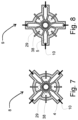
- Fig. 2 to 5 are cross sections through the shaft furnace 1 Fig. 1 at different levels.
- Figs. 2 and 3 show the combustion chamber levels 8, 9 in a cross-sectional view, for example Fig. 2 the upper combustion chamber level 8 and Fig. 3 represents the lower combustion chamber level 9.
- Each combustion chamber level 8, 9 has, for example, four combustion chambers 4, 5, which are preferably star-shaped in the combustion chamber 20 are arranged and evenly spaced from one another. It is also conceivable that one or more combustion chamber levels 8, 9 have more or fewer than four combustion chambers 4, 5.
- the combustion chambers 4, 5 of the combustion chamber levels 8, 9 are, for example, arranged offset from one another at an angle of approximately 45°. Arrangements that deviate from this are also conceivable.
- the combustion chambers 4, 5 are preferably delimited by lateral transverse walls and opened downwards and upwards in the direction of the shaft 2, so that the gas heated in the combustion chamber 4, 5 flows into the combustion zone 20. Passages are arranged between adjacent combustion chambers 4, 5 so that the material and the gas can flow along the shaft 2.
- Figs. 4 and 5 each show an exemplary embodiment of a cross section through the plane of the gas outlet 12 of the cooling gas extraction device 29.
- the cooling gas extraction device 29 has only one gas outlet 12, which extends from the cooling gas extraction device 29 outwards from the shaft 2.
- the exemplary embodiment of the Fig. 5 has, for example, four gas outlets 12, which extend radially outwards from the cooling gas extraction device 29 in a star shape and are preferably evenly spaced from one another.
- the number of gas outlets 12 is, for example, one to ten.
- the gas outlets 12 are preferably each connected to a respective heat exchanger 35, so that the shaft furnace 1 has, for example, four heat exchangers 35. It is also conceivable that the shaft furnace 1 has only one, two or three heat exchangers 35 which are connected to the gas outlets 12.
- the number of gas outlets 12 preferably corresponds to the number of heat exchangers 35.
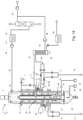
- a further exemplary embodiment of a shaft furnace 1 is shown, the shaft furnace 1 being the same as in Fig. 1 shown shaft furnace 1 corresponds with the difference that the shaft furnace 1 Fig. 6 a plurality of additional burners, in particular side burners 38.
- a plurality of side burners 38 are mounted in each combustion chamber level 8, 9 in addition to the burners 10 arranged in the combustion chambers 4, 5.
- the side burners 38 are each connected to the fuel line via the respective fuel ring line 14, 15 and to the Oxidant supply line 16 is connected via the respective oxidant ring line 17, 18.
- the side burners 38 of the respective combustion chamber levels 8, 9 are each arranged between adjacent combustion chambers 4, 5 and are preferably evenly spaced from one another. It is also conceivable that the side burners 38 are mounted above or below the combustion chamber levels 8, 9.
- the side burners 38 are, for example, burner lances that extend through the shaft wall into the burning zone.
- a further exemplary embodiment of a shaft furnace 1 is shown, the shaft furnace 1 being the same as in Fig. 1 shown shaft furnace 1 corresponds with the difference that the shaft furnace 1 Fig. 9 has no combustion chambers.
- the shaft furnace 1 of the Fig. 9 has only a plurality of side burners 38, which are mounted, for example, in two burner levels 51, 52 in the combustion zone 20.
- the burner lances 38 are mounted in the shaft wall in such a way that the insertion depth into the shaft 2 is variable.
- the side burners 38 are preferably mounted in the shaft wall so that they can be moved radially.
- the side burners 38 of a burner level 51, 52 for example, have the same insertion depth.
- the side burners of the first, upper burner level 51 preferably have a first insertion depth and the side burners 38 of the second, lower burner level 52 have a second insertion depth.
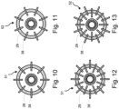
- Fig. 10 to 13 each show a burner level 51, 52 of the shaft furnace 1 Fig. 9 in a cross-sectional view.
- the burner levels 51, 52 each have the same number of side burners 38, although it is also conceivable that the burner levels 51, 52 have different numbers of side burners 38.
- the burner levels 51, 52 are, for example, arranged twisted to one another at an angle of approximately 22.5°.
- the burner levels 51, 52 of the 12 and 13 have side burners 38 of different insertion depths, with, for example, every second side burner 38 having a first insertion depth and the side burner 38 arranged between them having a second insertion depth. This enabled a cross-section of the shaft 2, especially the firing zone 20, uniform firing of the material.
- a further exemplary embodiment of a shaft furnace 1 is shown, the shaft furnace 1 being the same as in Fig. 1 shown shaft furnace 1 corresponds with the difference that the shaft furnace 1 Fig. 14 has no upper inner cylinder and the cooling gas extraction device 29 has an area which extends in height beyond the gas outlet 12 into the preheating zone 21, so that withdrawn cooling gas flows within the cooling gas extraction device 29 up to the height of the preheating zone 21.
- This cooling gas extraction device 29, which is extended in height, serves to equalize the material flow in the preheating zone 21 and when entering the combustion zone 20.
Landscapes
- Engineering & Computer Science (AREA)
- Mechanical Engineering (AREA)
- General Engineering & Computer Science (AREA)
- Environmental & Geological Engineering (AREA)
- Furnace Details (AREA)
- Vertical, Hearth, Or Arc Furnaces (AREA)
- Waste-Gas Treatment And Other Accessory Devices For Furnaces (AREA)
Applications Claiming Priority (3)
| Application Number | Priority Date | Filing Date | Title |
|---|---|---|---|
| DE102020202410.3A DE102020202410A1 (de) | 2020-02-25 | 2020-02-25 | Vorrichtung und Verfahren zum Brennen und/oder Kalzinieren von stückigem Gut |
| BE20205122A BE1028091B1 (de) | 2020-02-25 | 2020-02-25 | Vorrichtung und Verfahren zum Brennen und/oder Kalzinieren von stückigem Gut |
| PCT/EP2021/053985 WO2021170478A1 (de) | 2020-02-25 | 2021-02-18 | Vorrichtung und verfahren zum brennen und/oder kalzinieren von stückigem gut |
Publications (3)
| Publication Number | Publication Date |
|---|---|
| EP4111118A1 EP4111118A1 (de) | 2023-01-04 |
| EP4111118B1 true EP4111118B1 (de) | 2024-01-03 |
| EP4111118C0 EP4111118C0 (de) | 2024-01-03 |
Family
ID=74661395
Family Applications (2)
| Application Number | Title | Priority Date | Filing Date |
|---|---|---|---|
| EP21705954.2A Active EP4111118B1 (de) | 2020-02-25 | 2021-02-18 | Vorrichtung und verfahren zum brennen und/oder kalzinieren von stückigem gut |
| EP21712042.7A Active EP4111119B1 (de) | 2020-02-25 | 2021-02-18 | Vorrichtung und verfahren zum brennen und/oder kalzinieren von stückigem gut |
Family Applications After (1)
| Application Number | Title | Priority Date | Filing Date |
|---|---|---|---|
| EP21712042.7A Active EP4111119B1 (de) | 2020-02-25 | 2021-02-18 | Vorrichtung und verfahren zum brennen und/oder kalzinieren von stückigem gut |
Country Status (5)
| Country | Link |
|---|---|
| EP (2) | EP4111118B1 (pl) |
| CN (2) | CN115151774A (pl) |
| ES (1) | ES2972094T3 (pl) |
| PL (1) | PL4111119T3 (pl) |
| WO (2) | WO2021170478A1 (pl) |
Families Citing this family (8)
| Publication number | Priority date | Publication date | Assignee | Title |
|---|---|---|---|---|
| BE1028191B9 (fr) | 2020-04-07 | 2021-11-30 | Lhoist Rech Et Developpement Sa | Procédé de calcination de chaux ou dolomie et four droit annulaire mis en œuvre |
| BE1029119B1 (de) * | 2021-02-18 | 2022-09-12 | Thyssenkrupp Ag | Vorrichtung und Verfahren zum Brennen und/oder Kalzinieren von stückigem Gut |
| WO2022194593A1 (de) * | 2021-03-15 | 2022-09-22 | Maerz Ofenbau Ag | Schachtofen und verfahren zum brennen von karbonathaltigem material in einem schachtofen |
| PL4330614T3 (pl) * | 2021-04-27 | 2025-07-28 | Maerz Ofenbau Ag | Piec i sposób wypalania skał węglanowych |
| US20250251194A1 (en) * | 2022-04-08 | 2025-08-07 | thyssenkrupp Polysius GmbH | System and method for heat-treating mineral material |
| BE1030435B1 (de) * | 2022-04-08 | 2023-11-14 | Thyssenkrupp Ind Solutions Ag | Anlage und ein Verfahren zur Wärmebehandlung von mineralischem Material |
| EP4394295A1 (en) * | 2022-12-30 | 2024-07-03 | S.A. Lhoist Recherche Et Developpement | Process for calcining carbonated mineral stones in an annular vertical kiln and implemented kiln |
| EP4394299A1 (en) * | 2022-12-30 | 2024-07-03 | S.A. Lhoist Recherche Et Developpement | Process for calcining carbonated mineral stones in an annular vertical kiln and implemented kiln |
Family Cites Families (12)
| Publication number | Priority date | Publication date | Assignee | Title |
|---|---|---|---|---|
| CH378217A (de) | 1959-12-03 | 1964-05-31 | Von Roll Ag | Verfahren und Schachtofen zum kontinuierlichen Brennen von mineralischen Werkstoffen, wie Zementklinker, Kalk oder Dolomit |
| DE2722719C2 (de) | 1977-05-20 | 1982-05-06 | Rheinische Kalksteinwerke GmbH, 5603 Wülfrath | Kalkschachtofen |
| CH651650A5 (de) * | 1981-02-04 | 1985-09-30 | Steine & Erden Gmbh | Verfahren und schachtofen zum brennen von stueckigem brenngut. |
| DE3915986C1 (pl) * | 1989-05-04 | 1990-10-04 | Beckenbach Waermestelle Gmbh, 4000 Duesseldorf, De | |
| DE102009013935B3 (de) * | 2009-03-19 | 2010-07-01 | Messer Group Gmbh | Verfahren und Vorrichtung zur Kalkherstellung |
| CN201620107U (zh) * | 2009-07-21 | 2010-11-03 | 贾会平 | 多膛式石灰窑 |
| DE102010019330B4 (de) * | 2010-05-05 | 2013-11-07 | Ecoloop Gmbh | Verfahren zur Umwandlung von Carbonaten in Oxide |
| JP5636881B2 (ja) * | 2010-11-01 | 2014-12-10 | 宇部興産機械株式会社 | 竪型焼成炉 |
| DE102010060866B3 (de) | 2010-11-29 | 2012-02-16 | Maerz Ofenbau Ag | Vorrichtung und Verfahren zum Brennen und/oder Kalzinieren von stückigem Gut |
| CN102303956B (zh) * | 2011-07-22 | 2013-01-30 | 石家庄市新华工业炉有限公司 | 一种套筒式石灰窑 |
| CN203284334U (zh) * | 2013-03-07 | 2013-11-13 | 上海宝冶建设工业炉工程技术有限公司 | 节能型双筒石灰竖窑 |
| CN106986561B (zh) * | 2017-05-17 | 2023-05-02 | 江苏中圣园科技股份有限公司 | 环形石灰竖窑 |
-
2021
- 2021-02-18 PL PL21712042.7T patent/PL4111119T3/pl unknown
- 2021-02-18 WO PCT/EP2021/053985 patent/WO2021170478A1/de not_active Ceased
- 2021-02-18 CN CN202180016548.3A patent/CN115151774A/zh active Pending
- 2021-02-18 EP EP21705954.2A patent/EP4111118B1/de active Active
- 2021-02-18 EP EP21712042.7A patent/EP4111119B1/de active Active
- 2021-02-18 WO PCT/EP2021/053986 patent/WO2021170479A1/de not_active Ceased
- 2021-02-18 CN CN202180016576.5A patent/CN115190959A/zh active Pending
- 2021-02-18 ES ES21712042T patent/ES2972094T3/es active Active
Also Published As
| Publication number | Publication date |
|---|---|
| EP4111119A1 (de) | 2023-01-04 |
| WO2021170478A1 (de) | 2021-09-02 |
| ES2972094T3 (es) | 2024-06-11 |
| PL4111119T3 (pl) | 2024-05-13 |
| CN115151774A (zh) | 2022-10-04 |
| EP4111119C0 (de) | 2023-12-27 |
| EP4111118C0 (de) | 2024-01-03 |
| CN115190959A (zh) | 2022-10-14 |
| EP4111119B1 (de) | 2023-12-27 |
| WO2021170479A1 (de) | 2021-09-02 |
| EP4111118A1 (de) | 2023-01-04 |
Similar Documents
| Publication | Publication Date | Title |
|---|---|---|
| EP4111118B1 (de) | Vorrichtung und verfahren zum brennen und/oder kalzinieren von stückigem gut | |
| EP4330614B1 (de) | Ofen und verfahren zum brennen von karbonatgestein | |
| WO2022229120A1 (de) | Kalkofensystem zum brennen von karbonatgestein und verfahren zum umbau eines ggr-schachtofens in ein kalkofensystem mit einem schachtofen | |
| DE102010060866B3 (de) | Vorrichtung und Verfahren zum Brennen und/oder Kalzinieren von stückigem Gut | |
| DE102021204175A1 (de) | Kalkofensystem zum Brennen von Karbonatgestein und Verfahren zum Umbau eines GGR-Schachtofens in ein Kalkofensystem mit einem Schachtofen | |
| DE102021201549A1 (de) | Vorrichtung und Verfahren zum Brennen und/oder Kalzinieren von stückigem Gut | |
| DE102021202485A1 (de) | Schachtofen und Verfahren zum Brennen von karbonathaltigem Material in einem Schachtofen | |
| EP4308867A1 (de) | Schachtofen und verfahren zum brennen von karbonathaltigem material in einem schachtofen | |
| DE102023102447A1 (de) | Gleichstrom-Gegenstrom-Regenerativ-Schachtofen und Verfahren zum Brennen von Karbonatgestein | |
| BE1028091B1 (de) | Vorrichtung und Verfahren zum Brennen und/oder Kalzinieren von stückigem Gut | |
| BE1029119B1 (de) | Vorrichtung und Verfahren zum Brennen und/oder Kalzinieren von stückigem Gut | |
| BE1029198B1 (de) | Schachtofen und Verfahren zum Brennen von karbonathaltigem Material in einem Schachtofen | |
| BE1029344B1 (de) | Kalkofensystem zum Brennen von Karbonatgestein und Verfahren zum Umbau eines GGR-Schachtofens in ein Kalkofensystem mit einem Schachtofen | |
| BE1031596B1 (de) | Gleichstrom-Gegenstrom-Regenerativ-Schachtofen und Verfahren zum Brennen von Karbonatgestein | |
| BE1031308B1 (de) | Gleichstrom-Gegenstrom-Regenerativ-Schachtofen und Verfahren zum Brennen von Karbonatgestein | |
| DE102020202410A1 (de) | Vorrichtung und Verfahren zum Brennen und/oder Kalzinieren von stückigem Gut | |
| BE1032115B1 (de) | Gleichstrom-Gegenstrom-Regenerativ-Schachtofen und Verfahren zum Brennen von Karbonatgestein | |
| EP4577789B1 (de) | Gleichstrom-gegenstrom-regenerativ-schachtofen und verfahren zum brennen von karbonatgestein | |
| EP4430010B1 (de) | Ofen und verfahren zum brennen von karbonatgestein | |
| LU103028B1 (de) | Verfahren zur Schachtumsteuerung eines Gleichstrom-Gegenstrom-Regenerativ-Schachtofens | |
| DE102024117473A1 (de) | Schachtofen und Verfahren zum Brennen von karbonathaltigem Material in einem Schachtofen | |
| WO2024160706A1 (de) | Gleichstrom-gegenstrom-regenerativ-schachtofen und verfahren zum brennen von karbonatgestein | |
| WO2024078859A1 (de) | Verfahren zur schachtumsteuerung eines gleichstrom-gegenstrom-regenerativ-schachtofens | |
| BE1032706A1 (de) | Schachtofen und Verfahren zum Brennen von karbonathaltigem Material in einem Schachtofen | |
| WO2024231344A1 (de) | Gleichstrom-gegenstrom-regenerativ-schachtofen und verfahren zum brennen von karbonatgestein |
Legal Events
| Date | Code | Title | Description |
|---|---|---|---|
| STAA | Information on the status of an ep patent application or granted ep patent |
Free format text: STATUS: UNKNOWN |
|
| STAA | Information on the status of an ep patent application or granted ep patent |
Free format text: STATUS: THE INTERNATIONAL PUBLICATION HAS BEEN MADE |
|
| PUAI | Public reference made under article 153(3) epc to a published international application that has entered the european phase |
Free format text: ORIGINAL CODE: 0009012 |
|
| STAA | Information on the status of an ep patent application or granted ep patent |
Free format text: STATUS: REQUEST FOR EXAMINATION WAS MADE |
|
| 17P | Request for examination filed |
Effective date: 20220926 |
|
| AK | Designated contracting states |
Kind code of ref document: A1 Designated state(s): AL AT BE BG CH CY CZ DE DK EE ES FI FR GB GR HR HU IE IS IT LI LT LU LV MC MK MT NL NO PL PT RO RS SE SI SK SM TR |
|
| DAV | Request for validation of the european patent (deleted) | ||
| DAX | Request for extension of the european patent (deleted) | ||
| GRAP | Despatch of communication of intention to grant a patent |
Free format text: ORIGINAL CODE: EPIDOSNIGR1 |
|
| STAA | Information on the status of an ep patent application or granted ep patent |
Free format text: STATUS: GRANT OF PATENT IS INTENDED |
|
| GRAS | Grant fee paid |
Free format text: ORIGINAL CODE: EPIDOSNIGR3 |
|
| GRAA | (expected) grant |
Free format text: ORIGINAL CODE: 0009210 |
|
| STAA | Information on the status of an ep patent application or granted ep patent |
Free format text: STATUS: THE PATENT HAS BEEN GRANTED |
|
| INTG | Intention to grant announced |
Effective date: 20231115 |
|
| AK | Designated contracting states |
Kind code of ref document: B1 Designated state(s): AL AT BE BG CH CY CZ DE DK EE ES FI FR GB GR HR HU IE IS IT LI LT LU LV MC MK MT NL NO PL PT RO RS SE SI SK SM TR |
|
| REG | Reference to a national code |
Ref country code: GB Ref legal event code: FG4D Free format text: NOT ENGLISH |
|
| REG | Reference to a national code |
Ref country code: DE Ref legal event code: R096 Ref document number: 502021002365 Country of ref document: DE |
|
| REG | Reference to a national code |
Ref country code: CH Ref legal event code: EP |
|
| REG | Reference to a national code |
Ref country code: IE Ref legal event code: FG4D Free format text: LANGUAGE OF EP DOCUMENT: GERMAN |
|
| U01 | Request for unitary effect filed |
Effective date: 20240103 |
|
| U07 | Unitary effect registered |
Designated state(s): AT BE BG DE DK EE FI FR IT LT LU LV MT NL PT SE SI Effective date: 20240108 |
|
| PG25 | Lapsed in a contracting state [announced via postgrant information from national office to epo] |
Ref country code: ES Free format text: LAPSE BECAUSE OF FAILURE TO SUBMIT A TRANSLATION OF THE DESCRIPTION OR TO PAY THE FEE WITHIN THE PRESCRIBED TIME-LIMIT Effective date: 20240103 |
|
| PG25 | Lapsed in a contracting state [announced via postgrant information from national office to epo] |
Ref country code: ES Free format text: LAPSE BECAUSE OF FAILURE TO SUBMIT A TRANSLATION OF THE DESCRIPTION OR TO PAY THE FEE WITHIN THE PRESCRIBED TIME-LIMIT Effective date: 20240103 |
|
| U20 | Renewal fee for the european patent with unitary effect paid |
Year of fee payment: 4 Effective date: 20240325 |
|
| PG25 | Lapsed in a contracting state [announced via postgrant information from national office to epo] |
Ref country code: IS Free format text: LAPSE BECAUSE OF FAILURE TO SUBMIT A TRANSLATION OF THE DESCRIPTION OR TO PAY THE FEE WITHIN THE PRESCRIBED TIME-LIMIT Effective date: 20240503 |
|
| PG25 | Lapsed in a contracting state [announced via postgrant information from national office to epo] |
Ref country code: GR Free format text: LAPSE BECAUSE OF FAILURE TO SUBMIT A TRANSLATION OF THE DESCRIPTION OR TO PAY THE FEE WITHIN THE PRESCRIBED TIME-LIMIT Effective date: 20240404 |
|
| PG25 | Lapsed in a contracting state [announced via postgrant information from national office to epo] |
Ref country code: HR Free format text: LAPSE BECAUSE OF FAILURE TO SUBMIT A TRANSLATION OF THE DESCRIPTION OR TO PAY THE FEE WITHIN THE PRESCRIBED TIME-LIMIT Effective date: 20240103 Ref country code: RS Free format text: LAPSE BECAUSE OF FAILURE TO SUBMIT A TRANSLATION OF THE DESCRIPTION OR TO PAY THE FEE WITHIN THE PRESCRIBED TIME-LIMIT Effective date: 20240403 |
|
| PG25 | Lapsed in a contracting state [announced via postgrant information from national office to epo] |
Ref country code: CZ Free format text: LAPSE BECAUSE OF FAILURE TO SUBMIT A TRANSLATION OF THE DESCRIPTION OR TO PAY THE FEE WITHIN THE PRESCRIBED TIME-LIMIT Effective date: 20240103 |
|
| PG25 | Lapsed in a contracting state [announced via postgrant information from national office to epo] |
Ref country code: RS Free format text: LAPSE BECAUSE OF FAILURE TO SUBMIT A TRANSLATION OF THE DESCRIPTION OR TO PAY THE FEE WITHIN THE PRESCRIBED TIME-LIMIT Effective date: 20240403 Ref country code: NO Free format text: LAPSE BECAUSE OF FAILURE TO SUBMIT A TRANSLATION OF THE DESCRIPTION OR TO PAY THE FEE WITHIN THE PRESCRIBED TIME-LIMIT Effective date: 20240403 Ref country code: IS Free format text: LAPSE BECAUSE OF FAILURE TO SUBMIT A TRANSLATION OF THE DESCRIPTION OR TO PAY THE FEE WITHIN THE PRESCRIBED TIME-LIMIT Effective date: 20240503 Ref country code: HR Free format text: LAPSE BECAUSE OF FAILURE TO SUBMIT A TRANSLATION OF THE DESCRIPTION OR TO PAY THE FEE WITHIN THE PRESCRIBED TIME-LIMIT Effective date: 20240103 Ref country code: GR Free format text: LAPSE BECAUSE OF FAILURE TO SUBMIT A TRANSLATION OF THE DESCRIPTION OR TO PAY THE FEE WITHIN THE PRESCRIBED TIME-LIMIT Effective date: 20240404 Ref country code: CZ Free format text: LAPSE BECAUSE OF FAILURE TO SUBMIT A TRANSLATION OF THE DESCRIPTION OR TO PAY THE FEE WITHIN THE PRESCRIBED TIME-LIMIT Effective date: 20240103 |
|
| PG25 | Lapsed in a contracting state [announced via postgrant information from national office to epo] |
Ref country code: PL Free format text: LAPSE BECAUSE OF FAILURE TO SUBMIT A TRANSLATION OF THE DESCRIPTION OR TO PAY THE FEE WITHIN THE PRESCRIBED TIME-LIMIT Effective date: 20240103 |
|
| PG25 | Lapsed in a contracting state [announced via postgrant information from national office to epo] |
Ref country code: PL Free format text: LAPSE BECAUSE OF FAILURE TO SUBMIT A TRANSLATION OF THE DESCRIPTION OR TO PAY THE FEE WITHIN THE PRESCRIBED TIME-LIMIT Effective date: 20240103 |
|
| REG | Reference to a national code |
Ref country code: CH Ref legal event code: PL |
|
| REG | Reference to a national code |
Ref country code: DE Ref legal event code: R097 Ref document number: 502021002365 Country of ref document: DE |
|
| PG25 | Lapsed in a contracting state [announced via postgrant information from national office to epo] |
Ref country code: SM Free format text: LAPSE BECAUSE OF FAILURE TO SUBMIT A TRANSLATION OF THE DESCRIPTION OR TO PAY THE FEE WITHIN THE PRESCRIBED TIME-LIMIT Effective date: 20240103 |
|
| PG25 | Lapsed in a contracting state [announced via postgrant information from national office to epo] |
Ref country code: CH Free format text: LAPSE BECAUSE OF NON-PAYMENT OF DUE FEES Effective date: 20240229 |
|
| PG25 | Lapsed in a contracting state [announced via postgrant information from national office to epo] |
Ref country code: SK Free format text: LAPSE BECAUSE OF FAILURE TO SUBMIT A TRANSLATION OF THE DESCRIPTION OR TO PAY THE FEE WITHIN THE PRESCRIBED TIME-LIMIT Effective date: 20240103 |
|
| PG25 | Lapsed in a contracting state [announced via postgrant information from national office to epo] |
Ref country code: SM Free format text: LAPSE BECAUSE OF FAILURE TO SUBMIT A TRANSLATION OF THE DESCRIPTION OR TO PAY THE FEE WITHIN THE PRESCRIBED TIME-LIMIT Effective date: 20240103 Ref country code: SK Free format text: LAPSE BECAUSE OF FAILURE TO SUBMIT A TRANSLATION OF THE DESCRIPTION OR TO PAY THE FEE WITHIN THE PRESCRIBED TIME-LIMIT Effective date: 20240103 Ref country code: RO Free format text: LAPSE BECAUSE OF FAILURE TO SUBMIT A TRANSLATION OF THE DESCRIPTION OR TO PAY THE FEE WITHIN THE PRESCRIBED TIME-LIMIT Effective date: 20240103 Ref country code: CH Free format text: LAPSE BECAUSE OF NON-PAYMENT OF DUE FEES Effective date: 20240229 |
|
| PLBE | No opposition filed within time limit |
Free format text: ORIGINAL CODE: 0009261 |
|
| STAA | Information on the status of an ep patent application or granted ep patent |
Free format text: STATUS: NO OPPOSITION FILED WITHIN TIME LIMIT |
|
| PG25 | Lapsed in a contracting state [announced via postgrant information from national office to epo] |
Ref country code: MC Free format text: LAPSE BECAUSE OF FAILURE TO SUBMIT A TRANSLATION OF THE DESCRIPTION OR TO PAY THE FEE WITHIN THE PRESCRIBED TIME-LIMIT Effective date: 20240103 |
|
| PG25 | Lapsed in a contracting state [announced via postgrant information from national office to epo] |
Ref country code: MC Free format text: LAPSE BECAUSE OF FAILURE TO SUBMIT A TRANSLATION OF THE DESCRIPTION OR TO PAY THE FEE WITHIN THE PRESCRIBED TIME-LIMIT Effective date: 20240103 |
|
| 26N | No opposition filed |
Effective date: 20241007 |
|
| PG25 | Lapsed in a contracting state [announced via postgrant information from national office to epo] |
Ref country code: IE Free format text: LAPSE BECAUSE OF NON-PAYMENT OF DUE FEES Effective date: 20240218 |
|
| PG25 | Lapsed in a contracting state [announced via postgrant information from national office to epo] |
Ref country code: IE Free format text: LAPSE BECAUSE OF NON-PAYMENT OF DUE FEES Effective date: 20240218 Ref country code: CH Free format text: LAPSE BECAUSE OF NON-PAYMENT OF DUE FEES Effective date: 20240229 |
|
| PGRI | Patent reinstated in contracting state [announced from national office to epo] |
Ref country code: CH Effective date: 20241104 |
|
| U20 | Renewal fee for the european patent with unitary effect paid |
Year of fee payment: 5 Effective date: 20250221 |
|
| PGFP | Annual fee paid to national office [announced via postgrant information from national office to epo] |
Ref country code: CH Payment date: 20250301 Year of fee payment: 5 |
|
| PG25 | Lapsed in a contracting state [announced via postgrant information from national office to epo] |
Ref country code: CY Free format text: LAPSE BECAUSE OF FAILURE TO SUBMIT A TRANSLATION OF THE DESCRIPTION OR TO PAY THE FEE WITHIN THE PRESCRIBED TIME-LIMIT; INVALID AB INITIO Effective date: 20210218 |
|
| PG25 | Lapsed in a contracting state [announced via postgrant information from national office to epo] |
Ref country code: HU Free format text: LAPSE BECAUSE OF FAILURE TO SUBMIT A TRANSLATION OF THE DESCRIPTION OR TO PAY THE FEE WITHIN THE PRESCRIBED TIME-LIMIT; INVALID AB INITIO Effective date: 20210218 |
|
| GBPC | Gb: european patent ceased through non-payment of renewal fee |
Effective date: 20250218 |
|
| PG25 | Lapsed in a contracting state [announced via postgrant information from national office to epo] |
Ref country code: TR Free format text: LAPSE BECAUSE OF FAILURE TO SUBMIT A TRANSLATION OF THE DESCRIPTION OR TO PAY THE FEE WITHIN THE PRESCRIBED TIME-LIMIT Effective date: 20240103 |
|
| PG25 | Lapsed in a contracting state [announced via postgrant information from national office to epo] |
Ref country code: GB Free format text: LAPSE BECAUSE OF NON-PAYMENT OF DUE FEES Effective date: 20250218 |
|
| REG | Reference to a national code |
Ref country code: CH Ref legal event code: U11 Free format text: ST27 STATUS EVENT CODE: U-0-0-U10-U11 (AS PROVIDED BY THE NATIONAL OFFICE) Effective date: 20260301 |
|
| U20 | Renewal fee for the european patent with unitary effect paid |
Year of fee payment: 6 Effective date: 20260225 |