EP4110671B1 - System und verfahren zur einstellung einer geplanten trajektorie eines autonomen fahrzeugs - Google Patents
System und verfahren zur einstellung einer geplanten trajektorie eines autonomen fahrzeugs Download PDFInfo
- Publication number
- EP4110671B1 EP4110671B1 EP21760629.2A EP21760629A EP4110671B1 EP 4110671 B1 EP4110671 B1 EP 4110671B1 EP 21760629 A EP21760629 A EP 21760629A EP 4110671 B1 EP4110671 B1 EP 4110671B1
- Authority
- EP
- European Patent Office
- Prior art keywords
- vehicle
- trajectory
- coordinate frame
- planned
- planned trajectory
- Prior art date
- Legal status (The legal status is an assumption and is not a legal conclusion. Google has not performed a legal analysis and makes no representation as to the accuracy of the status listed.)
- Active
Links
Images




Classifications
-
- G—PHYSICS
- G05—CONTROLLING; REGULATING
- G05D—SYSTEMS FOR CONTROLLING OR REGULATING NON-ELECTRIC VARIABLES
- G05D1/00—Control of position, course, altitude or attitude of land, water, air or space vehicles, e.g. using automatic pilots
- G05D1/02—Control of position or course in two dimensions
- G05D1/021—Control of position or course in two dimensions specially adapted to land vehicles
- G05D1/0212—Control of position or course in two dimensions specially adapted to land vehicles with means for defining a desired trajectory
-
- G—PHYSICS
- G05—CONTROLLING; REGULATING
- G05D—SYSTEMS FOR CONTROLLING OR REGULATING NON-ELECTRIC VARIABLES
- G05D1/00—Control of position, course, altitude or attitude of land, water, air or space vehicles, e.g. using automatic pilots
- G05D1/02—Control of position or course in two dimensions
- G05D1/021—Control of position or course in two dimensions specially adapted to land vehicles
- G05D1/0212—Control of position or course in two dimensions specially adapted to land vehicles with means for defining a desired trajectory
- G05D1/0217—Control of position or course in two dimensions specially adapted to land vehicles with means for defining a desired trajectory in accordance with energy consumption, time reduction or distance reduction criteria
-
- B—PERFORMING OPERATIONS; TRANSPORTING
- B60—VEHICLES IN GENERAL
- B60W—CONJOINT CONTROL OF VEHICLE SUB-UNITS OF DIFFERENT TYPE OR DIFFERENT FUNCTION; CONTROL SYSTEMS SPECIALLY ADAPTED FOR HYBRID VEHICLES; ROAD VEHICLE DRIVE CONTROL SYSTEMS FOR PURPOSES NOT RELATED TO THE CONTROL OF A PARTICULAR SUB-UNIT
- B60W30/00—Purposes of road vehicle drive control systems not related to the control of a particular sub-unit, e.g. of systems using conjoint control of vehicle sub-units
- B60W30/10—Path keeping
-
- B—PERFORMING OPERATIONS; TRANSPORTING
- B60—VEHICLES IN GENERAL
- B60W—CONJOINT CONTROL OF VEHICLE SUB-UNITS OF DIFFERENT TYPE OR DIFFERENT FUNCTION; CONTROL SYSTEMS SPECIALLY ADAPTED FOR HYBRID VEHICLES; ROAD VEHICLE DRIVE CONTROL SYSTEMS FOR PURPOSES NOT RELATED TO THE CONTROL OF A PARTICULAR SUB-UNIT
- B60W60/00—Drive control systems specially adapted for autonomous road vehicles
- B60W60/001—Planning or execution of driving tasks
-
- B—PERFORMING OPERATIONS; TRANSPORTING
- B60—VEHICLES IN GENERAL
- B60W—CONJOINT CONTROL OF VEHICLE SUB-UNITS OF DIFFERENT TYPE OR DIFFERENT FUNCTION; CONTROL SYSTEMS SPECIALLY ADAPTED FOR HYBRID VEHICLES; ROAD VEHICLE DRIVE CONTROL SYSTEMS FOR PURPOSES NOT RELATED TO THE CONTROL OF A PARTICULAR SUB-UNIT
- B60W60/00—Drive control systems specially adapted for autonomous road vehicles
- B60W60/001—Planning or execution of driving tasks
- B60W60/0011—Planning or execution of driving tasks involving control alternatives for a single driving scenario, e.g. planning several paths to avoid obstacles
-
- B—PERFORMING OPERATIONS; TRANSPORTING
- B60—VEHICLES IN GENERAL
- B60W—CONJOINT CONTROL OF VEHICLE SUB-UNITS OF DIFFERENT TYPE OR DIFFERENT FUNCTION; CONTROL SYSTEMS SPECIALLY ADAPTED FOR HYBRID VEHICLES; ROAD VEHICLE DRIVE CONTROL SYSTEMS FOR PURPOSES NOT RELATED TO THE CONTROL OF A PARTICULAR SUB-UNIT
- B60W60/00—Drive control systems specially adapted for autonomous road vehicles
- B60W60/001—Planning or execution of driving tasks
- B60W60/0015—Planning or execution of driving tasks specially adapted for safety
-
- G—PHYSICS
- G05—CONTROLLING; REGULATING
- G05D—SYSTEMS FOR CONTROLLING OR REGULATING NON-ELECTRIC VARIABLES
- G05D1/00—Control of position, course, altitude or attitude of land, water, air or space vehicles, e.g. using automatic pilots
- G05D1/0088—Control of position, course, altitude or attitude of land, water, air or space vehicles, e.g. using automatic pilots characterized by the autonomous decision making process, e.g. artificial intelligence, predefined behaviours
-
- B—PERFORMING OPERATIONS; TRANSPORTING
- B60—VEHICLES IN GENERAL
- B60W—CONJOINT CONTROL OF VEHICLE SUB-UNITS OF DIFFERENT TYPE OR DIFFERENT FUNCTION; CONTROL SYSTEMS SPECIALLY ADAPTED FOR HYBRID VEHICLES; ROAD VEHICLE DRIVE CONTROL SYSTEMS FOR PURPOSES NOT RELATED TO THE CONTROL OF A PARTICULAR SUB-UNIT
- B60W2420/00—Indexing codes relating to the type of sensors based on the principle of their operation
- B60W2420/40—Photo, light or radio wave sensitive means, e.g. infrared sensors
- B60W2420/403—Image sensing, e.g. optical camera
-
- B—PERFORMING OPERATIONS; TRANSPORTING
- B60—VEHICLES IN GENERAL
- B60W—CONJOINT CONTROL OF VEHICLE SUB-UNITS OF DIFFERENT TYPE OR DIFFERENT FUNCTION; CONTROL SYSTEMS SPECIALLY ADAPTED FOR HYBRID VEHICLES; ROAD VEHICLE DRIVE CONTROL SYSTEMS FOR PURPOSES NOT RELATED TO THE CONTROL OF A PARTICULAR SUB-UNIT
- B60W2420/00—Indexing codes relating to the type of sensors based on the principle of their operation
- B60W2420/40—Photo, light or radio wave sensitive means, e.g. infrared sensors
- B60W2420/408—Radar; Laser, e.g. lidar
-
- B—PERFORMING OPERATIONS; TRANSPORTING
- B60—VEHICLES IN GENERAL
- B60W—CONJOINT CONTROL OF VEHICLE SUB-UNITS OF DIFFERENT TYPE OR DIFFERENT FUNCTION; CONTROL SYSTEMS SPECIALLY ADAPTED FOR HYBRID VEHICLES; ROAD VEHICLE DRIVE CONTROL SYSTEMS FOR PURPOSES NOT RELATED TO THE CONTROL OF A PARTICULAR SUB-UNIT
- B60W2520/00—Input parameters relating to overall vehicle dynamics
- B60W2520/10—Longitudinal speed
-
- B—PERFORMING OPERATIONS; TRANSPORTING
- B60—VEHICLES IN GENERAL
- B60W—CONJOINT CONTROL OF VEHICLE SUB-UNITS OF DIFFERENT TYPE OR DIFFERENT FUNCTION; CONTROL SYSTEMS SPECIALLY ADAPTED FOR HYBRID VEHICLES; ROAD VEHICLE DRIVE CONTROL SYSTEMS FOR PURPOSES NOT RELATED TO THE CONTROL OF A PARTICULAR SUB-UNIT
- B60W2520/00—Input parameters relating to overall vehicle dynamics
- B60W2520/10—Longitudinal speed
- B60W2520/105—Longitudinal acceleration
Definitions
- Planning and navigation systems for an autonomous vehicle often have to correct for discrepancies between a planned path and a physical position of the vehicle. For example, as the estimated physical position is an estimate of the actual physical position, some error or discrepancies in position can occur during operations. Thus, the vehicle must often correct for the error by realigning with the planned path while still maintaining a smooth ride for the passages free from irregular or sporadic changes of direction.
- GB2570887A describes planning a feasible vehicle trajectory to reach a target state that is both reachable under vehicle constraints, and allowable on a road segment.
- US2019/0196485 A1 describes a system which generates a driving trajectory from a starting point to a destination point for an ADV.
- the autonomous vehicle operates using two coordinate frames.
- the first coordinate frame may be relative to the vehicle (e.g., a vehicle body-centric coordinate frame), such that a position of the vehicle in the first coordinate frame remains substantially smooth or stable as the vehicle traverses the planned route.
- the vehicle may also maintain a second coordinate frame that is based on a location of the vehicle on the surface of the Earth (e.g., a Euclidian coordinate frame), such as Universal Transverse Mercator (UTM) coordinate frame or a longitudinal/latitudinal coordinate frame.
- UDM Universal Transverse Mercator
- the planning architecture of the autonomous vehicle may compensate for differences between an estimated state and a planned path without the use of a separate system.
- the planning architecture may include a mission planning system, a decision system, and a tracking system that together output a trajectory for a drive system.
- the mission planning system may generate a planned route of the vehicle from a first location to a second location.
- the decision system may maintain, adjust, or generate planned trajectories of the vehicle based on the planned route and the estimated state or position of the vehicle and taking into account any objects that may be proximate the vehicle, and the tracking system may generate correction trajectories to compensate for variances between the planned route and the planned trajectory (e.g., to assist with keeping the vehicle on the planned trajectory).
- the example process may also include projecting the estimated state onto the planned trajectory within the first (e.g., body-centric) frame and then converting the projected state or position into the second (e.g., Euclidian) coordinate frame prior to the tracking system generating the correction trajectory.
- first e.g., body-centric
- second e.g., Euclidian
- an autonomous vehicle may be initially at an estimated position of (0, 0) within the first coordinate frame and at an estimated position of (100, 100) in the second coordinate frame.
- the previous planning decision may include a planned trajectory that starts at (0, 0) in the first coordinate frame and at (100, 100) in the second frame, such that there is zero distance between the position of the vehicle and the decision trajectory (e.g., both are at (0, 0) first coordinate frame and (100, 100) second coordinate frame during the first period of time.
- the estimated state of the vehicle received from the position sensors is at (99, 100) in second coordinate frame, e.g., the estimated state is 1 unit of measure different than the expected state or position.
- the vehicle either due to error in the position sensor or drift by the vehicle (and/or any associated algorithms), is no longer along the planned trajectory or the planned route.
- the vehicle may project, in the first coordinate frame, the estimated state onto the previous planned trajectory to determine a projected state or position along the previous planned trajectory.
- the vehicle may first convert the estimated state, which is received in the second coordinate frame, into the first coordinate frame.
- the first coordinate frame is relative to the vehicle (e.g., body-centric)
- both the expected state and the estimated state of the vehicle are the same.
- the projected state may be a distance from the estimated position of the vehicle.
- the projected state may be transformed into the second coordinate frame using transformations determined with respect the state of the vehicle during a previous period of time and a new planned trajectory may be determined using the projected state and the planned route.
- the estimated state and the new planned trajectory may be provided to the tracking system.
- the tracking system may then generate a correction trajectory to further compensate for any discrepancies between the estimated state and the newly planned trajectory, as well as to compensate for any detected nearby objects.
- the techniques described herein can be implemented in a number of ways. Example implementations are provided below with reference to the following figures. Although discussed in the context of an autonomous vehicle, the methods, apparatuses, and systems described herein can be applied to a variety of systems (e.g., a sensor system or a robotic platform), and are not limited to autonomous vehicles. In one example, similar techniques may be utilized in driver-controlled vehicles in which such a system may provide an indication of whether it is safe to perform various maneuvers. In another example, the techniques can be utilized in a manufacturing assembly line context, in an aerial surveying context, or in a nautical context. Additionally, the techniques described herein can be used with real data (e.g., captured using sensor(s)), simulated data (e.g., generated by a simulator), or any combination of the two.
- real data e.g., captured using sensor(s)
- simulated data e.g., generated by a simulator
- FIG. 1 is an example pictorial diagram 100 illustrating transformations associated with a planning architecture, as described herein.
- the vehicle may have an expected state or position 102 and a position system of the vehicle may return an estimated state 104.
- both the expected state or position 102 and the estimate state or position 104 are shown in both a first coordinate frame 106 (e.g., a body centric coordinate frame) and a second coordinate frame 108 (e.g., a Euclidian coordinate frame).
- a first coordinate frame 106 e.g., a body centric coordinate frame
- a second coordinate frame 108 e.g., a Euclidian coordinate frame
- the vehicle has a planned route 122 from a planning system and a previously planned trajectory 112 from a decision system.
- the expected state 102 differs from the previously planned trajectory 112 by a first distance and the estimated state 104 differs from the expected state 102 by an additional or second distance.
- the estimated state 104 and the previously planned trajectory 112 are transformed into the first coordinate frame 106 and the estimated state 104 is projected 114 in the first coordinate frame 106 as shown to determine a projected state or position 116 along the previously planned trajectory 112.
- the projected state or position 116 may be a distance 110 from the position estimate 104 in the first coordinate frame 106 as shown.
- the projected state 116 is then transformed into the second coordinate frame 108.
- the vehicle may then plan from the projected state 116 in the second coordinate frame (e.g., the Euclidian coordinate frame) to determine a new planned trajectory 118.
- the vehicle may plan from a position 116 that is closer to the vehicle, than if a projection between the estimated state 104 and the previously planned trajectory 112 was determined in the second coordinate frame.
- the vehicle plan from a position 116 that is closer to the estimated state 104 the vehicle is better able to plan around nearby obstacles.
- the new planned trajectory 118 may then be provided to a tracking system to generate the correction trajectory 120 to compensate for the distance 110 between the projected state 116 and the estimated state 104.
- the correction trajectory 120 generated by the tracking system may be calculated using fewer processing resources and in less time, thereby improving decision and reaction time of the vehicle which ultimately improves the operational safely of the vehicle
- FIG. 2 is an example timing 200 diagram in a Euclidian coordinate system illustrating an autonomous vehicle utilizing a planning architecture, as described herein.
- a vehicle 202 traversing a planned route 204 via a first planned trajectory 206 is shown.
- the vehicle 202 may be at a first position 208 along the first planned trajectory 206(A).
- a first planned trajectory 206(A) may be determined in order to promote the vehicle 202 to follow the planned route 204 based on various data (distance from the route 204, obstacles, etc.).
- the vehicle 202 may have shifted (e.g., either due to error in the position system (sensor discrepancy, algorithm discrepancy, and/or otherwise) or drift during navigation) to a position 210.
- the vehicle 202 may be a first distance 212 from the first planned trajectory 206(A).
- the vehicle 202 may generate a first correction trajectory 214 and, thus, have an expected state or position 216, during a third period of time t 2 .
- the planning architecture of the vehicle 202 may transform the first planned trajectory 206(A) and the estimated state 218 into the first coordinate frame, causing the first planned trajectory 206(A) to be positioned relative to the vehicle 202 as shown by first transformed planned trajectory 206(B).
- the vehicle 202 may then perform a projection 220 to determine a projected state 222 along the first planned trajectory 206(A) within the first coordinate frame.
- the projected state 222 may then be transferred back into the second coordinate frame at the position shown.
- the vehicle 202 may then determine a second planned trajectory 224 based on the projected state 222 within the second coordinate frame.
- a second planned trajectory may represent a trajectory for the vehicle 202 to return to the route 204 from the first transformed planned trajectory 206(B) in a similar fashion as if the planning had been performed at the first transformed trajectory 206(A).
- the current planning process allows the vehicle 202 to determine the second planned trajectory 224 from the projected state 222 that is closer to the estimated state 218 of the vehicle 202 than the position 226 along the first planned trajectory 206(A) thereby improving safety over convectional planning systems.
- an object 230 e.g., the tree
- a planned trajectory not shown
- the vehicle 202 may still be offset or may be a distance from the second planned trajectory 224. In these cases, the vehicle 202 may determine a correction trajectory 228 to bring the vehicle 202 closer to or onto the planned trajectory 224. Again, since the planned trajectory 224 is physical closer to the estimated state 218, the calculations to determine the correction trajectory 228 are reduced and, as such, reduce time periods associated with decision and planning, thereby improving overall safety of the vehicle 202.
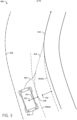
- FIG. 3 is an example pictorial diagram 300 of an autonomous vehicle 302 utilizing a planning architecture, described above with respect to FIGS. 1 and 2 .
- the vehicle 302 is traveling within a planned path or route 304 having a route reference 306 (e.g., a side or center of a lane).
- the vehicle 302 also has a previous planned trajectory 308(A) in the second coordinate system (e.g., within the Euclidian coordinate frame illustrated in FIG. 3 ).
- the previous planned trajectory 308(A) may be in the form of an arc (e.g., the vehicle 302 is not moving in a straight line as in FIGS. 1 and 2 ).
- an actual state of the vehicle 302 (position, velocity, yaw, heading, etc.) represented by 310 may differ from an expected state 312, which may also be offset from the planned trajectory 308(A) as shown.
- the previously planned trajectory 308(A) may be transformed into the first coordinate frame (e.g., the vehicle or body-centric coordinate frame) as shown as previously planned trajectory 308(B). It should be noted, that as FIG. 3 is shown in the second coordinate frame and the previously planned trajectory 308(B) in the first coordinate frame, the location of the previously planned trajectory 308(B) relative to the estimated state reflects the position of the previously planned trajectory 308(A) relative to the expected state 312 of the vehicle 302.
- the vehicle 302 may then project the estimated state 310 onto the previous planned trajectory 308(B), generally indicated by projection 314, to identify the projected state 316.
- the projection 314 is based on a shortest distance between the estimated state 310 of the vehicle 302 and the previous decision trajectory 308(B).
- the projected state 316 may then transformed into the second coordinate frame using transformations determined with respect the state of the vehicle during a current period of time.
- the vehicle 302 may then determine a new planned trajectory 318 starting from the projected state 316 in the second coordinate frame and returning the vehicle 302 to the planned path 304, as shown. However, in some cases, the vehicle 302 may still be offset from the new planned trajectory 318.
- the point 310 may be at any fixed position on the vehicle 302.
- the point 310 may be along the front or rear axle as well as other positions.
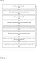
- FIG. 4 is a flow diagram illustrating example process 400 associated with the planning architecture according to some implementations.
- the processes are illustrated as a collection of blocks in a logical flow diagram, which represent a sequence of operations, some or all of which can be implemented in hardware, software, or a combination thereof.
- the blocks represent computer-executable instructions stored on one or more computer-readable media that, which when executed by one or more processors, perform the recited operations.
- computer-executable instructions include routines, programs, objects, components, encryption, deciphering, compressing, recording, data structures and the like that perform particular functions or implement particular abstract data types.
- an estimated state of an autonomous vehicle may move or jump due to changes in data received from various position sensors.
- the jumps in estimated state may result in back and forth or jerky movement of the vehicle without proper compensation by the planning architecture or systems of the vehicle.
- FIG. 4 is a flow diagram illustrating an example process 400 associated with the planning architecture, as described herein.
- the process 400 may be used by, for instance, an autonomous vehicle to compensate for differences between an estimated state and a planned path by projecting the estimated state on to a planned trajectory within a first (body-centric) coordinate frame and then converting the projected state into the second (e.g., Euclidian) coordinate frame prior to the tracking system generating the correction trajectory.
- an autonomous vehicle to compensate for differences between an estimated state and a planned path by projecting the estimated state on to a planned trajectory within a first (body-centric) coordinate frame and then converting the projected state into the second (e.g., Euclidian) coordinate frame prior to the tracking system generating the correction trajectory.
- the system may receive or access a planned trajectory.
- the planned trajectory may be associated with a previous period of time.
- the planned trajectory may be in the first coordinate frame, the second coordinate frame, or both.
- the system may receive or determine transforms associated with the planned trajectory between the first coordinate frame and a second coordinate frame.
- the transforms may be determined during a previous period of time, such as during the period of time in which the planned trajectory was determined.
- the transforms may be stored at a location that is accessible by the systems of the planning architecture.
- the system may receive an estimated state.
- the estimated state may be received from one or more position sensors or systems associated with the position sensors.
- the position sensors may include an inertial measurement unit (IMU), Global Position System (GPS) sensors or Global Navigation Satellite System (GNSS) sensors as well as other types of position sensors.
- the position may be estimated based on captured image, lidar, or radar data of a physical environment surrounding the vehicle as well as one or more stored environment maps.
- the operation 406 may include localizing a vehicle in an environment based on a captured data (e.g., lidar, radar, image) with respect to a map (e.g., a mesh or data structure comprising multi-resolution covariance data).
- the estimated state may be within the second coordinate frame.
- the system may transform the estimated state into the first coordinate frame (e.g., the body-centric coordinate frame).
- the estimated state and the planned trajectory may be compared within the first coordinate frame. Additionally, it should be understood, that as the first coordinate frame is relative to the vehicle, a position of the vehicle does not move even with the corresponding jump in the estimated state.
- the system may project the estimated state onto the planned trajectory in the first coordinate frame. For example, as discussed above with respect to FIGS. 1-3 , the system may project the estimated state onto the planned trajectory by determining a shortest distance between the planned trajectory and the estimated state.
- the system may determine a projected state in the first coordinate frame. For example, the position on the planned trajectory that is the shortest distance from the estimated state may be selected or used as the projected state.
- the system may then determine a new planned trajectory in the second coordinate frame based at least in part on the projected state. For example, the system may determine a new trajectory to return the vehicle from the projected state to the planned path accommodating for any nearby objects.
- the system may output the new planned trajectory and the estimated state to a tracker system. For example, some offset between the estimated state and the new planned trajectory may still exist, as the new planned trajectory is determined from the projected state. In these cases, the tracker system may determine a correction trajectory between the estimated state and the new planned trajectory that avoids any nearby objects, as discussed above.
- FIG. 5 is a block diagram illustrating an example planning architecture 500, as described herein.
- the planning architecture 500 may include a planning system 502, a decision system 504, and a tracking system 506.
- the planning system 502 may generate a planned path 508 for the vehicle from a first location to a second location.
- the decision system 504 may maintain, adjust, or generate planned trajectories, such as planned trajectories 510(A) and 510(B), of the vehicle based on the planned path 508 and an estimated state 514 of the vehicle taking into account any objects that may be proximate the vehicle.
- the decision system 504 may receive the estimated state 514 of the vehicle and project the estimated state 514 onto a previously planned trajectory 510(A) to determine a projection position 516, as discussed above.
- the decision system 504 may then generate a new planned trajectory 510(C) based on the projected state 516 and the planned path 508 as shown.
- the tracking system 506 may generate correction trajectories 518 to be followed by a drive system 512 to compensate for variances between the planned path 508 and the planned trajectory 510(C) (e.g., to assist with keeping the vehicle on the planned trajectory 510(C).
- FIG. 6 is a block diagram of an example system 600 for implementing the techniques described herein, in accordance with embodiments of the disclosure.
- the system 600 may include one or multiple features, components, and/or functionality of embodiments described herein with reference to FIGS. 1-5 .
- the system 600 may include a vehicle 602.
- the vehicle 602 may include a vehicle computing device 604, one or more sensor systems 606, one or more communication connections 608, and one or more drive systems 610.
- the vehicle computing device 604 may include one or more processors 612 and computer readable media 614 communicatively coupled with the one or more processors 612.
- the vehicle 602 is an autonomous vehicle; however, the vehicle 602 could be any other type of vehicle, or any other system (e.g., a robotic system, a camera enabled smartphone, etc.).
- the computer readable media 614 of the vehicle computing device 604 stores a planning system 616 and system controllers 618 as well as trajectories 620, position data 622, coordinate frames 624, and transforms 626 between the coordinate frames 624. Though depicted in FIG.
- the planning system 616 and the system controllers 618 as well as the trajectories 620, the position data 622, the coordinate frames 624, and the transforms 626 may additionally, or alternatively, be accessible to the vehicle 602 (e.g., stored on, or otherwise accessible by, computer readable media remote from the vehicle 602).
- the planning system 616 may be configured to implement one or more processes for compensating for deviations between measured and desired states of the vehicle as described with respect to any of FIGS. 1-5 herein.
- the vehicle computing device 604 can include one or more system controllers 618, which can be configured to control steering, propulsion, braking, safety, emitters, communication, and other systems of the vehicle 602. These system controller(s) 618 may communicate with and/or control corresponding systems of the drive system(s) 610 and/or other components of the vehicle 602. In some instances, aspects of some or all of the components discussed herein can include any models, algorithms, and/or machine learning algorithms.
- the sensor system(s) 606 can include lidar sensors, radar sensors, ultrasonic transducers, sonar sensors, location sensors (e.g., GPS, compass, etc.), inertial sensors (e.g., inertial measurement units (IMUs), accelerometers, magnetometers, gyroscopes, etc.), cameras (e.g., RGB, IR, intensity, depth, time of flight, etc.), microphones, wheel encoders, environment sensors (e.g., temperature sensors, humidity sensors, light sensors, pressure sensors, etc.), and one or more time of flight (ToF) sensors, etc.
- the sensor system(s) 606 can include multiple instances of each of these or other types of sensors.
- the vehicle 602 can also include one or more communication connection(s) 608 that enable communication between the vehicle 602 and one or more other local or remote computing device(s).
- the communication connection(s) 608 may facilitate communication with other local computing device(s) on the vehicle 602 and/or the drive system(s) 610.
- the communication connection(s) 608 may allow the vehicle 602 to communicate with other nearby computing device(s) (e.g., other nearby vehicles, traffic signals, etc.).
- the communications connection(s) 608 also enable the vehicle 602 to communicate with remote teleoperations computing device or other remote services.
- the communications connection(s) 608 may include physical and/or logical interfaces for connecting the vehicle computing device 604 to another computing device (e.g., computing device(s) 630) and/or a network, such as network(s) 628.
- the communications connection(s) 608 may enable Wi-Fi-based communication such as via frequencies defined by the IEEE 802.11 standards, short range wireless frequencies such as Bluetooth ® , cellular communication (e.g., 2G, 3G, 4G, 4G LTE, 5G, etc.) or any suitable wired or wireless communications protocol that enables the respective computing device to interface with the other computing device(s).
- the vehicle 602 can include one or more drive systems 610.
- the vehicle 602 may have a single drive system 610.
- individual drive systems 610 can be positioned on opposite ends of the vehicle 602 (e.g., the front and the rear, etc.).
- the drive system(s) 610 can include one or more sensor systems 606 to detect conditions of the drive system(s) 610 and/or the surroundings of the vehicle 602, as discussed above.
- the sensor system(s) 606 can include one or more wheel encoders (e.g., rotary encoders) to sense rotation of the wheels of the drive systems, inertial sensors (e.g., inertial measurement units, accelerometers, gyroscopes, magnetometers, etc.) to measure orientation and acceleration of the drive system, cameras or other image sensors, ultrasonic sensors to acoustically detect objects in the surroundings of the drive system, lidar sensors, radar sensors, etc. Some sensors, such as the wheel encoders may be unique to the drive system(s) 610. In some cases, the sensor system(s) 606 on the drive system(s) 610 can overlap or supplement corresponding systems of the vehicle 602.
- wheel encoders e.g., rotary encoders
- inertial sensors e.g., inertial measurement units, accelerometers, gyroscopes, magnetometers, etc.
- ultrasonic sensors to acoustically detect objects in the surroundings of the drive system
- the components discussed herein can process sensor data, such as position data 622, as described above, and may send their respective outputs, over the one or more network(s) 628, to one or more computing device(s) 630. In at least one example, the components discussed herein may send their respective outputs to the one or more computing device(s) 630 at a particular frequency, after a lapse of a predetermined period of time, in near real-time, etc.
- machine learning algorithms can include, but are not limited to, regression algorithms (e.g., ordinary least squares regression (OLSR), linear regression, logistic regression, stepwise regression, multivariate adaptive regression splines (MARS), locally estimated scatterplot smoothing (LOESS)), instance-based algorithms (e.g., ridge regression, least absolute shrinkage and selection operator (LASSO), elastic net, least-angle regression (LARS)), decisions tree algorithms (e.g., classification and regression tree (CART), iterative dichotomiser 3 (ID3), Chi-squared automatic interaction detection (CHAID), decision stump, conditional decision trees), Bayesian algorithms (e.g., naive Bayes, Gaussian naive Bayes, multinomial naive Bayes, average one-dependence estimators (AODE), Bayesian belief network (BNN), Bayesian networks), clustering algorithms (e.g., k-means
- the processor(s) 612 of the vehicle 602 and the processor(s) 632 of the computing device(s) 630 may be any suitable processor capable of executing instructions to process data and perform operations as described herein.
- the processor(s) 612 and 632 can comprise one or more Central Processing Units (CPUs), Graphics Processing Units (GPUs), or any other device or portion of a device that processes electronic data to transform that electronic data into other electronic data that can be stored in registers and/or computer readable media.
- integrated circuits e.g., ASICs, etc.
- gate arrays e.g., FPGAs, etc.
- other hardware devices can also be considered processors in so far as they are configured to implement encoded instructions.
- Computer readable media 614 and 634 are examples of non-transitory computer-readable media.
- the computer readable media 614 and 634 can store an operating system and one or more software applications, instructions, programs, and/or data to implement the methods described herein and the functions attributed to the various systems.
- the computer readable media can be implemented using any suitable computer readable media technology, such as static random access memory (SRAM), synchronous dynamic RAM (SDRAM), nonvolatile/Flash-type memory, or any other type of computer readable media capable of storing information.
- SRAM static random access memory
- SDRAM synchronous dynamic RAM
- Flash-type memory any other type of computer readable media capable of storing information.
- the architectures, systems, and individual elements described herein can include many other logical, programmatic, and physical components, of which those shown in the accompanying figures are merely examples that are related to the discussion herein.
- FIG. 6 is illustrated as a distributed system, in alternative examples, components of the vehicle 602 can be associated with the computing device(s) 630 and/or components of the computing device(s) 630 can be associated with the vehicle 602. That is, the vehicle 602 can perform one or more of the functions associated with the computing device(s) 630, and vice versa. Further, aspects of machine learning component 638 can be performed on any of the devices discussed herein.
Landscapes
- Engineering & Computer Science (AREA)
- Automation & Control Theory (AREA)
- Mechanical Engineering (AREA)
- Transportation (AREA)
- Physics & Mathematics (AREA)
- Aviation & Aerospace Engineering (AREA)
- Radar, Positioning & Navigation (AREA)
- Remote Sensing (AREA)
- General Physics & Mathematics (AREA)
- Human Computer Interaction (AREA)
- Health & Medical Sciences (AREA)
- Business, Economics & Management (AREA)
- Artificial Intelligence (AREA)
- Evolutionary Computation (AREA)
- Game Theory and Decision Science (AREA)
- Medical Informatics (AREA)
- Traffic Control Systems (AREA)
- Control Of Driving Devices And Active Controlling Of Vehicle (AREA)
- Control Of Position, Course, Altitude, Or Attitude Of Moving Bodies (AREA)
Claims (13)
- Verfahren, das Folgendes umfasst:Bestimmen (412) eines projizierten Zustands (116, 222, 316, 516) eines autonomen Fahrzeugs durch Projizieren, innerhalb eines ersten Koordinatenrahmens, eines geschätzten Zustands (104, 218, 310, 514), der mit dem autonomen Fahrzeug assoziiert ist, auf eine erste geplante Trajektorie (112, 206, 308B, 510A, 510B) des autonomen Fahrzeugs (202, 302), wobei Projizieren des geschätzten Zustands auf die erste geplante Trajektorie Bestimmen einer kürzesten Distanz zwischen der ersten geplanten Trajektorie und dem geschätzten Zustand umfasst, und Auswählen der Position auf der ersten geplanten Trajektorie, die der kürzeste Abstand von dem geschätzten Zustand ist, als der projizierte Zustand;Bestimmen (414), zumindest teilweise basierend auf einem zweiten Koordinatenrahmen, einer zweiten geplanten Trajektorie (118, 224, 318, 510C), die mit dem autonomen Fahrzeug assoziiert ist, zumindest teilweise basierend auf dem projizierten Zustand und einem geplanten Pfad, der mit dem autonomen Fahrzeug assoziiert ist; undSteuern des autonomen Fahrzeugs zumindest teilweise basierend auf der zweiten geplanten Trajektorie.
- Verfahren nach Anspruch 1, wobei der geschätzte Zustand eine gemessene Position und/oder eine gemessene Orientierung und/oder eine gemessene Beschleunigung und/oder eine gemessene Geschwindigkeit umfasst, die mit dem autonomen Fahrzeug assoziiert ist.
- Verfahren nach Anspruch 1 oder 2, wobei der erste Koordinatenrahmen ein Fahrzeugkarosserie-zentrierter Koordinatenrahmen ist und der zweite Koordinatenrahmen ein euklidischer Koordinatenrahmen ist.
- Verfahren nach einem der Ansprüche 1 bis 3, wobei die zweite geplante Trajektorie ferner zumindest teilweise auf einem Zustand eines Objekts basiert, das durch das autonome Fahrzeug detektiert wird.
- Verfahren nach einem der Ansprüche 1 bis 4, das ferner Folgendes umfasst:Bestimmen, zumindest teilweise basierend auf dem zweiten Koordinatenrahmen, einer Korrekturtrajektorie (228, 320, 518), die mit dem autonomen Fahrzeug assoziiert ist, zumindest teilweise basierend auf dem geschätzten Zustand, der mit dem autonomen Fahrzeug assoziiert ist, und der zweiten geplanten Trajektorie; undwobei Steuern des autonomen Fahrzeugs zumindest teilweise auf der Korrekturtrajektorie basiert.
- Verfahren nach Anspruch 5, wobei die Korrekturtrajektorie ferner zumindest teilweise auf einem Zustand eines Objekts basiert, das durch das autonome Fahrzeug detektiert wird.
- Verfahren nach einem der Ansprüche 1 bis 6, wobei die zweite geplante Trajektorie, wenn sie durch das autonome Fahrzeug ausgeführt wird, das autonome Fahrzeug veranlasst, zu dem geplanten Pfad zurückzukehren.
- Computerprogrammprodukt, das codierte Anweisungen umfasst, die bei Ausführung auf einem Computer ein Verfahren nach einem der Ansprüche 1 bis 7 implementieren.
- System, das Folgendes umfasst:einen oder mehrere Prozessoren (612) undein oder mehrere nicht-flüchtige computerlesbare Medien (614), die Anweisungen speichern, die durch den einen oder die mehreren Prozessoren ausführbar sind, wobei die Anweisung dann, wenn sie ausgeführt wird, das System veranlasst, Operationen durchzuführen, die Folgendes umfassen:Bestimmen (412) eines projizierten Zustands (116, 222, 316, 516) eines Fahrzeugs durch Projizieren, zumindest teilweise basierend auf einem ersten Koordinatenrahmen, eines geschätzten Zustands (104, 218, 310, 514), der mit dem Fahrzeug assoziiert ist, auf eine erste geplante Trajektorie (112, 206, 308B, 510A, 510B) des Fahrzeugs (202, 302), wobei Projizieren des geschätzten Zustands auf die erste geplante Trajektorie Bestimmen einer kürzesten Distanz zwischen der ersten geplanten Trajektorie und dem geschätzten Zustand umfasst, und Auswählen der Position auf der ersten geplanten Trajektorie, die der kürzeste Abstand von dem geschätzten Zustand ist, als der projizierte Zustand;Bestimmen (414), zumindest teilweise basierend auf einem zweiten Koordinatenrahmen, einer zweiten geplanten Trajektorie (118, 224, 318, 510C), die mit dem Fahrzeug assoziiert ist, zumindest teilweise basierend auf dem projizierten Zustand und einem geplanten Pfad, der mit dem Fahrzeug assoziiert ist, wobei der geplante Pfad eine Route für das Fahrzeug zwischen einem ersten Ort und einem zweiten Ort umfasst; undBestimmen, mit dem zweiten Koordinatenrahmen, einer Korrekturtrajektorie, die mit dem Fahrzeug assoziiert ist, zumindest teilweise basierend auf dem geschätzten Zustand, der mit dem Fahrzeug assoziiert ist, und der zweiten geplanten Trajektorie.
- System nach Anspruch 9, wobei:der erste Koordinatenrahmen relativ zu einer Karosserie des Fahrzeugs ist; undder zweite Koordinatenrahmen ein UTM-Koordinatenrahmen (Universal Transverse Mercator) ist.
- System nach einem der Ansprüche 9 oder 10, wobei die Operationen ferner Steuern des Fahrzeugs zumindest teilweise basierend auf der Korrekturtrajektorie umfassen.
- System nach Anspruch 11, wobei die Operationen ferner Folgendes umfassen:Bestimmen einer Korrekturtrajektorie (228, 320, 518), die mit dem Fahrzeug assoziiert ist, zumindest teilweise basierend auf dem geschätzten Zustand, der mit dem Fahrzeug assoziiert ist, und der zweiten geplanten Trajektorie; undwobei Steuern des Fahrzeugs zumindest teilweise auf der Korrekturtrajektorie basiert.
- System nach Anspruch 12, wobei:die Korrekturtrajektorie zumindest teilweise basierend auf dem zweiten Koordinatenrahmen bestimmt wird; unddie Korrekturtrajektorie das Fahrzeug veranlasst, zu der zweiten geplanten Trajektorie zurückzukehren.
Applications Claiming Priority (2)
| Application Number | Priority Date | Filing Date | Title |
|---|---|---|---|
| US16/805,118 US11841708B2 (en) | 2020-02-28 | 2020-02-28 | System and method for adjusting a planned trajectory of an autonomous vehicle |
| PCT/US2021/017182 WO2021173336A1 (en) | 2020-02-28 | 2021-02-09 | System and method for adjusting a planned trajectory of an autonomous vehicle |
Publications (3)
| Publication Number | Publication Date |
|---|---|
| EP4110671A1 EP4110671A1 (de) | 2023-01-04 |
| EP4110671A4 EP4110671A4 (de) | 2024-04-03 |
| EP4110671B1 true EP4110671B1 (de) | 2025-04-09 |
Family
ID=77464148
Family Applications (1)
| Application Number | Title | Priority Date | Filing Date |
|---|---|---|---|
| EP21760629.2A Active EP4110671B1 (de) | 2020-02-28 | 2021-02-09 | System und verfahren zur einstellung einer geplanten trajektorie eines autonomen fahrzeugs |
Country Status (5)
| Country | Link |
|---|---|
| US (1) | US11841708B2 (de) |
| EP (1) | EP4110671B1 (de) |
| JP (1) | JP7662655B2 (de) |
| CN (1) | CN115151470A (de) |
| WO (1) | WO2021173336A1 (de) |
Families Citing this family (5)
| Publication number | Priority date | Publication date | Assignee | Title |
|---|---|---|---|---|
| US11628858B2 (en) * | 2020-09-15 | 2023-04-18 | Baidu Usa Llc | Hybrid planning system for autonomous vehicles |
| CN114715184B (zh) * | 2022-03-07 | 2025-07-22 | 清华大学 | 基于车云协同的智能网联汽车分层决策与控制方法及装置 |
| CN115092212B (zh) * | 2022-07-14 | 2024-03-22 | 北京世纪东方智汇科技股份有限公司 | 隧道内列车轨迹校准方法、装置、设备及介质 |
| US20250002047A1 (en) * | 2023-06-30 | 2025-01-02 | Zoox, Inc. | Trajectory selection in response to triggering events |
| CN117400945B (zh) * | 2023-12-15 | 2024-02-23 | 广汽埃安新能源汽车股份有限公司 | 一种基于单目视觉信息的车辆控制方法及装置 |
Family Cites Families (24)
| Publication number | Priority date | Publication date | Assignee | Title |
|---|---|---|---|---|
| JP5233606B2 (ja) * | 2008-11-19 | 2013-07-10 | 富士通株式会社 | 絶対移動経路算出装置及び方法、並びにプログラム |
| US20120158247A1 (en) * | 2010-12-15 | 2012-06-21 | William Robert Norris | Perception Model For Trajectory Following Autonomous And Human Augmented Steering Control |
| DE102012014468A1 (de) * | 2012-07-21 | 2014-05-15 | Volkswagen Aktiengesellschaft | Verfahren zum Verändern einer Fahrstrategie für ein Fahrzeug und Fahrzeugsteuergerät für ein Fahrzeug |
| US9120485B1 (en) * | 2012-09-14 | 2015-09-01 | Google Inc. | Methods and systems for smooth trajectory generation for a self-driving vehicle |
| US9405293B2 (en) * | 2014-05-30 | 2016-08-02 | Nissan North America, Inc | Vehicle trajectory optimization for autonomous vehicles |
| US10248124B2 (en) * | 2016-07-21 | 2019-04-02 | Mobileye Vision Technologies, Inc. | Localizing vehicle navigation using lane measurements |
| JP6852299B2 (ja) * | 2016-08-09 | 2021-03-31 | 株式会社デンソー | 運転支援システム |
| US10379538B1 (en) | 2017-03-20 | 2019-08-13 | Zoox, Inc. | Trajectory generation using motion primitives |
| US11410673B2 (en) | 2017-05-03 | 2022-08-09 | Soltare Inc. | Audio processing for vehicle sensory systems |
| US10768011B2 (en) * | 2017-08-31 | 2020-09-08 | Wipro Limited | Method and system for positioning an autonomous vehicle on a navigation map |
| JP6972793B2 (ja) * | 2017-09-04 | 2021-11-24 | 日産自動車株式会社 | 運転支援車両の走行制御方法及び走行制御装置 |
| KR102374919B1 (ko) * | 2017-10-16 | 2022-03-16 | 주식회사 만도모빌리티솔루션즈 | 자율주행 지원 장치 및 방법 |
| US10841496B2 (en) * | 2017-10-19 | 2020-11-17 | DeepMap Inc. | Lidar to camera calibration based on edge detection |
| US10816990B2 (en) * | 2017-12-21 | 2020-10-27 | Baidu Usa Llc | Non-blocking boundary for autonomous vehicle planning |
| US10691129B2 (en) * | 2018-01-31 | 2020-06-23 | Baidu Usa Llc | Dynamically adjustable reference line sampling point density for autonomous vehicles |
| GB2570887B (en) | 2018-02-07 | 2020-08-12 | Jaguar Land Rover Ltd | A system for a vehicle |
| US11237004B2 (en) * | 2018-03-27 | 2022-02-01 | Uatc, Llc | Log trajectory estimation for globally consistent maps |
| US10614717B2 (en) * | 2018-05-17 | 2020-04-07 | Zoox, Inc. | Drive envelope determination |
| US10691130B2 (en) | 2018-06-06 | 2020-06-23 | Uatc, Llc | Gridlock solver for motion planning system of an autonomous vehicle |
| US10782136B2 (en) * | 2018-09-28 | 2020-09-22 | Zoox, Inc. | Modifying map elements associated with map data |
| DE102018221864A1 (de) * | 2018-12-17 | 2020-06-18 | Volkswagen Aktiengesellschaft | Verfahren und System zum Bestimmen einer Trajektorie eines Fahrzeugs |
| US11435194B2 (en) * | 2019-01-28 | 2022-09-06 | Uatc, Llc | Scaffolds for globally consistent maps |
| JP7260385B2 (ja) * | 2019-04-24 | 2023-04-18 | トヨタ自動車株式会社 | 車両走行制御装置 |
| DE102019126631A1 (de) * | 2019-10-02 | 2021-04-08 | Valeo Schalter Und Sensoren Gmbh | Verbesserte Trajektorienschätzung basierend auf Ground Truth |
-
2020
- 2020-02-28 US US16/805,118 patent/US11841708B2/en active Active
-
2021
- 2021-02-09 EP EP21760629.2A patent/EP4110671B1/de active Active
- 2021-02-09 WO PCT/US2021/017182 patent/WO2021173336A1/en not_active Ceased
- 2021-02-09 JP JP2022551549A patent/JP7662655B2/ja active Active
- 2021-02-09 CN CN202180016449.5A patent/CN115151470A/zh active Pending
Also Published As
| Publication number | Publication date |
|---|---|
| US11841708B2 (en) | 2023-12-12 |
| US20210271251A1 (en) | 2021-09-02 |
| JP7662655B2 (ja) | 2025-04-15 |
| CN115151470A (zh) | 2022-10-04 |
| JP2023514869A (ja) | 2023-04-11 |
| EP4110671A1 (de) | 2023-01-04 |
| WO2021173336A1 (en) | 2021-09-02 |
| EP4110671A4 (de) | 2024-04-03 |
Similar Documents
| Publication | Publication Date | Title |
|---|---|---|
| EP4110671B1 (de) | System und verfahren zur einstellung einer geplanten trajektorie eines autonomen fahrzeugs | |
| US12101572B2 (en) | Image scan line timestamping | |
| JP7640567B2 (ja) | レーダー追跡されたオブジェクト速度及び/又はヨー | |
| US11460568B2 (en) | Estimating in-plane velocity from an arbitrary radar return | |
| JP7462665B2 (ja) | 外観に基づく動きの予測 | |
| US12162513B2 (en) | Route-relative trajectory numerical integrator and controller using the same | |
| US11308363B2 (en) | Device and method for training an object detection model | |
| US11898873B2 (en) | Calibrating multiple inertial measurement units | |
| EP4065933B1 (de) | Korrektur von sensordatenabgleich und umgebungskartierung | |
| US11308391B2 (en) | Offline combination of convolutional/deconvolutional and batch-norm layers of convolutional neural network models for autonomous driving vehicles | |
| US20200099872A1 (en) | Multi-sensor data capture synchronization | |
| US11780464B2 (en) | Autonomous vehicle trajectory generation using velocity-based steering limits | |
| US20240174239A1 (en) | Route-relative trajectory generation and optimization computations incorporating vehicle sideslip | |
| EP3786586B1 (de) | Wegplanung für autonome und halbautonome fahrzeuge | |
| US20200363816A1 (en) | System and method for controlling autonomous vehicles | |
| US11543263B1 (en) | Map distortion determination | |
| US20240092397A1 (en) | Interpretable kalman filter comprising neural network component(s) for autonomous vehicles | |
| EP3857865B1 (de) | Zeitstempeln für bildabtastzeilen | |
| US12391265B2 (en) | Pose component | |
| US20250018954A1 (en) | Ground profile estimation for sensor data | |
| US20240383482A1 (en) | Ground profile estimation for sensor data | |
| US11787419B1 (en) | Robust numerically stable Kalman filter for autonomous vehicles | |
| WO2025024133A1 (en) | Dynamic, diverse, and computationally efficient vehicle candidate action generation | |
| WO2024163342A1 (en) | Object detection using similarity determinations for sensor observations | |
| US12172649B1 (en) | Ground profile estimation for sensor data |
Legal Events
| Date | Code | Title | Description |
|---|---|---|---|
| STAA | Information on the status of an ep patent application or granted ep patent |
Free format text: STATUS: THE INTERNATIONAL PUBLICATION HAS BEEN MADE |
|
| PUAI | Public reference made under article 153(3) epc to a published international application that has entered the european phase |
Free format text: ORIGINAL CODE: 0009012 |
|
| STAA | Information on the status of an ep patent application or granted ep patent |
Free format text: STATUS: REQUEST FOR EXAMINATION WAS MADE |
|
| 17P | Request for examination filed |
Effective date: 20220719 |
|
| AK | Designated contracting states |
Kind code of ref document: A1 Designated state(s): AL AT BE BG CH CY CZ DE DK EE ES FI FR GB GR HR HU IE IS IT LI LT LU LV MC MK MT NL NO PL PT RO RS SE SI SK SM TR |
|
| DAV | Request for validation of the european patent (deleted) | ||
| DAX | Request for extension of the european patent (deleted) | ||
| A4 | Supplementary search report drawn up and despatched |
Effective date: 20240301 |
|
| RIC1 | Information provided on ipc code assigned before grant |
Ipc: G05D 1/00 20060101ALI20240226BHEP Ipc: G08G 1/133 20060101ALI20240226BHEP Ipc: B60W 30/10 20060101ALI20240226BHEP Ipc: B60W 30/095 20120101ALI20240226BHEP Ipc: B60W 40/10 20120101ALI20240226BHEP Ipc: B60W 60/00 20200101AFI20240226BHEP |
|
| GRAP | Despatch of communication of intention to grant a patent |
Free format text: ORIGINAL CODE: EPIDOSNIGR1 |
|
| STAA | Information on the status of an ep patent application or granted ep patent |
Free format text: STATUS: GRANT OF PATENT IS INTENDED |
|
| INTG | Intention to grant announced |
Effective date: 20241127 |
|
| GRAS | Grant fee paid |
Free format text: ORIGINAL CODE: EPIDOSNIGR3 |
|
| P01 | Opt-out of the competence of the unified patent court (upc) registered |
Free format text: CASE NUMBER: APP_4423/2025 Effective date: 20250127 |
|
| GRAA | (expected) grant |
Free format text: ORIGINAL CODE: 0009210 |
|
| STAA | Information on the status of an ep patent application or granted ep patent |
Free format text: STATUS: THE PATENT HAS BEEN GRANTED |
|
| AK | Designated contracting states |
Kind code of ref document: B1 Designated state(s): AL AT BE BG CH CY CZ DE DK EE ES FI FR GB GR HR HU IE IS IT LI LT LU LV MC MK MT NL NO PL PT RO RS SE SI SK SM TR |
|
| REG | Reference to a national code |
Ref country code: GB Ref legal event code: FG4D |
|
| REG | Reference to a national code |
Ref country code: CH Ref legal event code: EP |
|
| REG | Reference to a national code |
Ref country code: DE Ref legal event code: R096 Ref document number: 602021028952 Country of ref document: DE |
|
| REG | Reference to a national code |
Ref country code: IE Ref legal event code: FG4D |
|
| REG | Reference to a national code |
Ref country code: SE Ref legal event code: TRGR |
|
| REG | Reference to a national code |
Ref country code: NL Ref legal event code: MP Effective date: 20250409 |
|
| PG25 | Lapsed in a contracting state [announced via postgrant information from national office to epo] |
Ref country code: NL Free format text: LAPSE BECAUSE OF FAILURE TO SUBMIT A TRANSLATION OF THE DESCRIPTION OR TO PAY THE FEE WITHIN THE PRESCRIBED TIME-LIMIT Effective date: 20250409 |
|
| REG | Reference to a national code |
Ref country code: AT Ref legal event code: MK05 Ref document number: 1783298 Country of ref document: AT Kind code of ref document: T Effective date: 20250409 |
|
| PG25 | Lapsed in a contracting state [announced via postgrant information from national office to epo] |
Ref country code: FI Free format text: LAPSE BECAUSE OF FAILURE TO SUBMIT A TRANSLATION OF THE DESCRIPTION OR TO PAY THE FEE WITHIN THE PRESCRIBED TIME-LIMIT Effective date: 20250409 Ref country code: PT Free format text: LAPSE BECAUSE OF FAILURE TO SUBMIT A TRANSLATION OF THE DESCRIPTION OR TO PAY THE FEE WITHIN THE PRESCRIBED TIME-LIMIT Effective date: 20250811 Ref country code: ES Free format text: LAPSE BECAUSE OF FAILURE TO SUBMIT A TRANSLATION OF THE DESCRIPTION OR TO PAY THE FEE WITHIN THE PRESCRIBED TIME-LIMIT Effective date: 20250409 |
|
| REG | Reference to a national code |
Ref country code: LT Ref legal event code: MG9D |
|
| PG25 | Lapsed in a contracting state [announced via postgrant information from national office to epo] |
Ref country code: GR Free format text: LAPSE BECAUSE OF FAILURE TO SUBMIT A TRANSLATION OF THE DESCRIPTION OR TO PAY THE FEE WITHIN THE PRESCRIBED TIME-LIMIT Effective date: 20250710 Ref country code: NO Free format text: LAPSE BECAUSE OF FAILURE TO SUBMIT A TRANSLATION OF THE DESCRIPTION OR TO PAY THE FEE WITHIN THE PRESCRIBED TIME-LIMIT Effective date: 20250709 |
|
| PG25 | Lapsed in a contracting state [announced via postgrant information from national office to epo] |
Ref country code: PL Free format text: LAPSE BECAUSE OF FAILURE TO SUBMIT A TRANSLATION OF THE DESCRIPTION OR TO PAY THE FEE WITHIN THE PRESCRIBED TIME-LIMIT Effective date: 20250409 |
|
| PG25 | Lapsed in a contracting state [announced via postgrant information from national office to epo] |
Ref country code: BG Free format text: LAPSE BECAUSE OF FAILURE TO SUBMIT A TRANSLATION OF THE DESCRIPTION OR TO PAY THE FEE WITHIN THE PRESCRIBED TIME-LIMIT Effective date: 20250409 |
|
| PG25 | Lapsed in a contracting state [announced via postgrant information from national office to epo] |
Ref country code: HR Free format text: LAPSE BECAUSE OF FAILURE TO SUBMIT A TRANSLATION OF THE DESCRIPTION OR TO PAY THE FEE WITHIN THE PRESCRIBED TIME-LIMIT Effective date: 20250409 |
|
| PG25 | Lapsed in a contracting state [announced via postgrant information from national office to epo] |
Ref country code: AT Free format text: LAPSE BECAUSE OF FAILURE TO SUBMIT A TRANSLATION OF THE DESCRIPTION OR TO PAY THE FEE WITHIN THE PRESCRIBED TIME-LIMIT Effective date: 20250409 |
|
| PG25 | Lapsed in a contracting state [announced via postgrant information from national office to epo] |
Ref country code: RS Free format text: LAPSE BECAUSE OF FAILURE TO SUBMIT A TRANSLATION OF THE DESCRIPTION OR TO PAY THE FEE WITHIN THE PRESCRIBED TIME-LIMIT Effective date: 20250709 |
|
| PG25 | Lapsed in a contracting state [announced via postgrant information from national office to epo] |
Ref country code: IS Free format text: LAPSE BECAUSE OF FAILURE TO SUBMIT A TRANSLATION OF THE DESCRIPTION OR TO PAY THE FEE WITHIN THE PRESCRIBED TIME-LIMIT Effective date: 20250809 |
|
| PG25 | Lapsed in a contracting state [announced via postgrant information from national office to epo] |
Ref country code: LV Free format text: LAPSE BECAUSE OF FAILURE TO SUBMIT A TRANSLATION OF THE DESCRIPTION OR TO PAY THE FEE WITHIN THE PRESCRIBED TIME-LIMIT Effective date: 20250409 |
|
| REG | Reference to a national code |
Ref country code: DE Ref legal event code: R097 Ref document number: 602021028952 Country of ref document: DE |
|
| PG25 | Lapsed in a contracting state [announced via postgrant information from national office to epo] |
Ref country code: DK Free format text: LAPSE BECAUSE OF FAILURE TO SUBMIT A TRANSLATION OF THE DESCRIPTION OR TO PAY THE FEE WITHIN THE PRESCRIBED TIME-LIMIT Effective date: 20250409 Ref country code: SM Free format text: LAPSE BECAUSE OF FAILURE TO SUBMIT A TRANSLATION OF THE DESCRIPTION OR TO PAY THE FEE WITHIN THE PRESCRIBED TIME-LIMIT Effective date: 20250409 |
|
| PG25 | Lapsed in a contracting state [announced via postgrant information from national office to epo] |
Ref country code: CZ Free format text: LAPSE BECAUSE OF FAILURE TO SUBMIT A TRANSLATION OF THE DESCRIPTION OR TO PAY THE FEE WITHIN THE PRESCRIBED TIME-LIMIT Effective date: 20250409 |
|
| PG25 | Lapsed in a contracting state [announced via postgrant information from national office to epo] |
Ref country code: EE Free format text: LAPSE BECAUSE OF FAILURE TO SUBMIT A TRANSLATION OF THE DESCRIPTION OR TO PAY THE FEE WITHIN THE PRESCRIBED TIME-LIMIT Effective date: 20250409 |
|
| PG25 | Lapsed in a contracting state [announced via postgrant information from national office to epo] |
Ref country code: SK Free format text: LAPSE BECAUSE OF FAILURE TO SUBMIT A TRANSLATION OF THE DESCRIPTION OR TO PAY THE FEE WITHIN THE PRESCRIBED TIME-LIMIT Effective date: 20250409 |
|
| PG25 | Lapsed in a contracting state [announced via postgrant information from national office to epo] |
Ref country code: IT Free format text: LAPSE BECAUSE OF FAILURE TO SUBMIT A TRANSLATION OF THE DESCRIPTION OR TO PAY THE FEE WITHIN THE PRESCRIBED TIME-LIMIT Effective date: 20250409 |
|
| PLBE | No opposition filed within time limit |
Free format text: ORIGINAL CODE: 0009261 |
|
| STAA | Information on the status of an ep patent application or granted ep patent |
Free format text: STATUS: NO OPPOSITION FILED WITHIN TIME LIMIT |
|
| REG | Reference to a national code |
Ref country code: CH Ref legal event code: L10 Free format text: ST27 STATUS EVENT CODE: U-0-0-L10-L00 (AS PROVIDED BY THE NATIONAL OFFICE) Effective date: 20260218 |
|
| 26N | No opposition filed |
Effective date: 20260112 |
|
| PGFP | Annual fee paid to national office [announced via postgrant information from national office to epo] |
Ref country code: SE Payment date: 20260223 Year of fee payment: 6 |
|
| PGFP | Annual fee paid to national office [announced via postgrant information from national office to epo] |
Ref country code: GB Payment date: 20260223 Year of fee payment: 6 |
|
| PGFP | Annual fee paid to national office [announced via postgrant information from national office to epo] |
Ref country code: DE Payment date: 20260220 Year of fee payment: 6 |
|
| PGFP | Annual fee paid to national office [announced via postgrant information from national office to epo] |
Ref country code: FR Payment date: 20260227 Year of fee payment: 6 |