EP4109474A1 - Câble à couche inscriptible discontinue à lisibilité ameliorée - Google Patents
Câble à couche inscriptible discontinue à lisibilité ameliorée Download PDFInfo
- Publication number
- EP4109474A1 EP4109474A1 EP22177434.2A EP22177434A EP4109474A1 EP 4109474 A1 EP4109474 A1 EP 4109474A1 EP 22177434 A EP22177434 A EP 22177434A EP 4109474 A1 EP4109474 A1 EP 4109474A1
- Authority
- EP
- European Patent Office
- Prior art keywords
- cable
- inscription
- color
- layer
- subset
- Prior art date
- Legal status (The legal status is an assumption and is not a legal conclusion. Google has not performed a legal analysis and makes no representation as to the accuracy of the status listed.)
- Withdrawn
Links
- 239000003086 colorant Substances 0.000 claims abstract description 7
- 239000000463 material Substances 0.000 claims description 5
- 238000000034 method Methods 0.000 claims description 5
- 238000000151 deposition Methods 0.000 claims description 3
- 238000007688 edging Methods 0.000 description 4
- 238000005520 cutting process Methods 0.000 description 3
- 238000010616 electrical installation Methods 0.000 description 2
- 238000009434 installation Methods 0.000 description 2
- 239000002390 adhesive tape Substances 0.000 description 1
- 230000004075 alteration Effects 0.000 description 1
- 238000010276 construction Methods 0.000 description 1
- 230000007613 environmental effect Effects 0.000 description 1
- 230000014759 maintenance of location Effects 0.000 description 1
- 238000004519 manufacturing process Methods 0.000 description 1
- 230000004048 modification Effects 0.000 description 1
- 238000012986 modification Methods 0.000 description 1
- 238000000275 quality assurance Methods 0.000 description 1
- 238000001228 spectrum Methods 0.000 description 1
- 238000003860 storage Methods 0.000 description 1
- 230000000007 visual effect Effects 0.000 description 1
Images
Classifications
-
- H—ELECTRICITY
- H01—ELECTRIC ELEMENTS
- H01B—CABLES; CONDUCTORS; INSULATORS; SELECTION OF MATERIALS FOR THEIR CONDUCTIVE, INSULATING OR DIELECTRIC PROPERTIES
- H01B7/00—Insulated conductors or cables characterised by their form
- H01B7/36—Insulated conductors or cables characterised by their form with distinguishing or length marks
- H01B7/365—Insulated conductors or cables characterised by their form with distinguishing or length marks being indicia imposed on the insulation or conductor
-
- H—ELECTRICITY
- H01—ELECTRIC ELEMENTS
- H01B—CABLES; CONDUCTORS; INSULATORS; SELECTION OF MATERIALS FOR THEIR CONDUCTIVE, INSULATING OR DIELECTRIC PROPERTIES
- H01B13/00—Apparatus or processes specially adapted for manufacturing conductors or cables
- H01B13/34—Apparatus or processes specially adapted for manufacturing conductors or cables for marking conductors or cables
-
- H—ELECTRICITY
- H01—ELECTRIC ELEMENTS
- H01B—CABLES; CONDUCTORS; INSULATORS; SELECTION OF MATERIALS FOR THEIR CONDUCTIVE, INSULATING OR DIELECTRIC PROPERTIES
- H01B7/00—Insulated conductors or cables characterised by their form
- H01B7/36—Insulated conductors or cables characterised by their form with distinguishing or length marks
- H01B7/361—Insulated conductors or cables characterised by their form with distinguishing or length marks being the colour of the insulation or conductor
Definitions
- the present invention relates to a cable comprising an inscription layer on its outer surface for the inscription of information on the cable itself, in particular to identify it in its environment, with improved readability.
- the invention belongs to the field of equipment for electric wires and electric cables in various sectors, such as construction or industry.
- the marking of one or more of the cables of the electrical installation facilitates the assembly and connection of this installation as well as reducing the risks associated with incorrect connection.
- it is known to position on a cable a ring, a piece of adhesive tape or another added element allowing the handwritten inscription of information.
- the marking of the cables by the use of added elements is not easy when installing the cables because this marking obliges the installer to handle both the cable itself, an added element and a means of inscription, such as a pen. This handling is made all the more difficult when the installation conditions are precarious, for example due to climatic conditions or the limited space available around the cable itself.
- a cable named Iris Tech and developed by the company Prysmian includes a continuous colored border extending over the entire length of the cable. Handwritten inscriptions may be made on this border.
- the stripe color is different for each cable size so that a visual identification of the stripe color helps to identify the section of the cable.
- the border is colored violet for a cable with a section of 4 mm 2 and blue for a cable with a section of 6 mm 2 .
- a major drawback of Iris Tech type cables is that the edging is not very suitable for handwritten inscription of information because the edging is narrow and its color can make the inscriptions very difficult to read, especially when the edging is purple or blue.
- the cable has been marked, it is difficult to find the information written on the edging because it can be positioned over the entire length of the cable. Identifying this information can therefore be difficult.
- the document US 2013/0240240 relates to a cable comprising a band applied to the outer surface of the cable for the handwritten inscription of information.
- the strip is designed in a detachable manner, ie the strip is withdrawn without causing deformation or alteration of the sheath surrounding the cable during its withdrawal.
- the modification of an initial marking can be carried out by replacing or removing the band identified by an inscription.
- the document FR 3 067 163 describes a discontinuous writable layer cable.
- the contrast between the message and the medium may prove to be insufficient for satisfactory readability, due to the possible width of the spectrum of colors which can be used by the installer to enter the information.
- the object of the present invention is to remedy the aforementioned drawbacks of the prior art.
- a longitudinally discontinuous inscription layer makes it possible to obtain a cable marking zone present at different positions along the length of the cable.
- the fact that the inscription layer is inseparable from the outer sheath of the cable makes it possible to guarantee the durability of the marking made on the cable by avoiding any untimely detachment.
- the color belongs to the subset of RAL Classic color codes 1000 to 1018, 1021 to 1037.
- the color belongs to the RAL Classic 2000 to 2017 color code subset.
- the color belongs to the subset of RAL Classic color codes 3012 to 3028.
- the color belongs to the RAL Classic 4003 to 4010 color code subset.
- the color belongs to the subset of RAL Classic color codes 6017 to 6019, 6021, 6027, 6034, 6037, 6038.
- the color belongs to the subset of RAL Classic color codes 7001, 7004, 7032, 7034, 7035, 7038, 7040, 7044, 7047, 7048.
- the color belongs to the subset of the RAL Classic 8023 color code.
- the color belongs to the subset of RAL Classic color codes 9001 to 9003, 9006 to 9010, 9012, 9016, 9018, 9022.
- the color belongs to the subset of RAL Design color codes 000 55 00 to 000 90 00, 010 50 50 to 010 93 05, 020 50 58 to 020 93 05, 030 50 60 to 030 93 05 , 040 50 70 to 040 93 05, 050 50 78 to 050 93 05, 060 60 80 to 060 93 05, 070 60 75 to 070 93 05, 075 70 80 to 075 93 05, 080 70 80 89, 050 50 60 to 085 93 05, 090 70 80 to 090 93 05, 095 50 50 to 095 93 05, 100 70 60 to 100 93 05, 110 60 65 to 110 96 02, 120 60 63 to 120 610 93 0 to 130 93 05, 140 60 70 to 140 93 05, 150 50 60 to 150 93 05, 160 70 50 to 160 93 05, 170 60 50 to 170 93 05
- the inscription layer forms an area suitable for the inscription of information.
- the area is suitable for the handwritten entry of information.
- the marking can be carried out by a pen directly on the writing layer. This makes it easier to identify the cable while allowing great flexibility to the user as to the entry of information.
- the inscription layer comprises at least two inscription portions separated longitudinally by a distance of between 10 cm and 10 m, preferably between 15 cm and 5 m, preferably between 20 cm and 1 m, preferably equal to 50 cm.
- each inscription portion extends longitudinally over a distance of between 3 cm and 10 cm and transversely over a distance of at least 3 mm, preferably at least 4 mm.
- the inscription layer extends transversely over the outer sheath over a distance of between 15% and 50%, preferably between 30% and 50%, of the outer diameter of the outer sheath.
- the inscription layer extends transversely around the outer sheath and forms a portion of a circle having an angle of between 54° and 180°, preferably between 90° and 180°, preferably between 108° and 180°, preferably 120°.
- the inscription layer is made by depositing material on the outer sheath.
- the inscription layer is printed on the outer sheath.
- the inscription layer is printed on the outer sheath by wheel marking or by ink jet marking, preferably by an electrophotography process.
- the writing layer is fluorescent and/or phosphorescent.
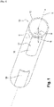
- FIG. 1 is a schematic perspective view of a cable according to the invention, in a particular embodiment.
- a cable 10 in accordance with the present invention comprises an outer sheath 12 and a longitudinally discontinuous inscription layer 14 formed on and inseparable from the outer sheath 12.
- the cable 10 can be an entire cable mounted on a storage reel or a portion of cable obtained after cutting an entire cable.
- the expression "longitudinally discontinuous” means the fact that the inscription layer 14 comprises at least one inscription portion 16 extending partially over the length of the cable 10 along the longitudinal axis A.
- the discontinuity of the inscription layer 14 does not imply having several inscription portions 16 but only that the inscription layer 14 does not extend over the entire length of the cable 10 along the longitudinal axis A
- the writing layer 14 comprises several writing portions 16, a gap is formed between two successive writing portions 16.
- insociable means the fact that the outer sheath 12 and the inscription layer 14 cannot be separated from each other without being altered or without affecting their integrity. Consequently, the inscription layer 14 is an integral part of the outer sheath 12.
- the cable 10 extends along a longitudinal axis A and has a substantially circular section defined by a radial axis B and a tangential axis C. These three longitudinal axes A, radial B and tangential C form a base, preferably orthonormal .
- substantially circular means any circular or quasi-circular section, for example of the flattened circular type.
- the cable 10 can have any shape allowing the registration layer 14 to be placed on the outer sheath 12.
- the inscription layer 14 extends over three dimensions along the longitudinal A, radial B and tangential C axes.
- the extension of the inscription layer 14 along the longitudinal A and tangential C axes defines a curved surface having a section defined by an angle D. This surface forms an inscription zone.
- the registration layer 14 has a thickness defined by the extension of the registration layer 14 along the radial axis B. In other words, the registration layer 14 has a tile shape at the surface of the outer sheath 12.
- the inscription layer 14 can extend longitudinally along a non-rectilinear path, for example along a helical path.
- the inscription layer 14 forms an area suitable for the inscription of information.
- the inscription layer 14 is made of a material allowing an ink to remain on the inscription layer 14 so as to guarantee the correct retention of the information over time.
- the writing layer 14 has a shade whose color belongs to a predetermined subset of colors.
- the following RAL color codes can be used depending on the color chosen for the inscription layer 14, RAL being the color coding system developed in 1927 by the German Institute for Quality Assurance and Associated Marking, in partnership with KemaNobel and dividing the colors into nine shades and coding them from 000 to 999 in each of the shades:
- the color may belong to the RAL Classic color code subset 1000 to 1018, 1021 to 1037.
- the color may belong to the RAL Classic 2000 to 2017 color code subset.
- the color may belong to the RAL Classic color code subset 3012 to 3028.
- the color may belong to the RAL Classic color code subset 4003 to 4010.
- the color may belong to the RAL Classic color code subset 6017 to 6019, 6021, 6027, 6034, 6037, 6038.
- the color may belong to the RAL Classic color code subset 7001, 7004, 7032, 7034, 7035, 7038, 7040, 7044, 7047, 7048.
- the color may belong to the subset of the RAL Classic 8023 color code.
- the color may belong to the RAL Classic color code subset 9001 to 9003, 9006 to 9010, 9012, 9016, 9018, 9022.
- Color can also belong to RAL Design color code subset 000 55 00 to 000 90 00, 010 50 50 to 010 93 05, 020 50 58 to 020 93 05, 030 50 60 to 030 93 05, 040 50 70 to 040 93 05, 050 50 78 to 050 93 05, 060 60 80 to 060 93 05, 070 60 75 to 070 93 05, 075 70 80 to 075 93 05, 080 70 88 to 080 93 05, 50 085 3 05, 090 70 80 to 090 93 05, 095 50 50 to 095 93 05, 100 70 60 to 100 93 05, 110 60 65 to 110 96 02, 120 60 63 to 120 93 05, 130 60 60 9 to 03 140 60 70 to 140 93 05, 150 50 60 to 150 93 05, 160 70 50 to 160 93 05, 170 60 50 to 170 93 05, 180 50 60 to 180 93
- each inscription portion 16 extends longitudinally, ie along the longitudinal axis A, over a distance of between 3 cm and 10 cm and transversely, ie along the tangential axis C, over a distance of at least 3 mm, preferably at least 4 mm.
- These dimensions of the writing layer 14 allow good readability of the information written thereon. Indeed, a character or glyph of usual size (for example of font size 11) has a height of approximately 3 mm.
- the height of the writing layer 14 is therefore at least equal to 3 mm to maintain good readability of the information written while having a reduced height of the writing layer 14.
- the height of the registration layer 14 is preferably at least equal to 4 mm to maintain a margin above and below the registration.
- the dimensions inscription portions 16 are identical along the same cable 10 to facilitate the production of the inscription layer 14.
- the writing layer 14 can be fluorescent and/or phosphorescent. It is thus possible to read the information written on the cable 10 in the dark.
- the zone formed by the inscription layer 14 can be adapted to the handwritten inscription of information.
- the inscription layer 14 is configured so that the ink of a pen can be maintained on the inscription layer 14 to mark the cable 10.
- the inscription layer 14 is also suitable for the handwritten inscription of information due to its dimensions. Indeed, the dimensions of the inscription layer 14 along the longitudinal A and tangential C axes are chosen so as to form a zone suitable for handwritten inscription. For this, the inscription layer 14 extends transversely, i.e. along the tangential axis C, on the outer sheath 12 over a distance of between 15% and 50%, preferably between 30% and 50%, of the outer diameter of the outer sheath 12, or more generally of the outer perimeter of the outer sheath 12 in a cross section to the longitudinal axis A.
- the inscription layer 14 can extend transversely, ie along the tangential axis C, around the outer sheath 12 and form a portion of a circle having an angle D between 54° and 180 °, preferably between 90° and 180°, preferably between 108° and 180°, preferably 120°.
- the angle D is defined in a plane perpendicular to the longitudinal axis A, ie according to a cross section of the cable 10.
- the inscription layer 14 is moreover defined so that each of the inscription portions 16 extends along the along the longitudinal axis A over a distance of between 3 cm and 30 cm, preferably between 3 cm and 20 cm, preferably between 3 cm and 10 cm. The larger the area of an inscription portion 16, the easier the inscription and a large amount of information can be carried on the inscription layer 14.
- the inscription layer 14 can be produced by depositing material on the outer sheath 12.
- the inscription layer 14 can be printed on the outer sheath 12.
- the material forming the layer of inscription 14 is in the form of an ink printed on the outer surface of the outer sheath 12.
- the inscription layer 14 is obtained by any process allowing the inscription layer 14 to be inseparable of the outer sheath 12 and to be formed in a longitudinally discontinuous manner along the longitudinal axis A.
- the process for obtaining the inscription layer 14 is chosen in particular so as to be able to produce an inscription layer 14 having a predetermined thickness or range of thicknesses.
- the term “thickness” is understood to mean the dimension of the inscription layer along the radial axis B.
- the inscription layer 14 is printed on the outer sheath 12 by roller marking or by ink jet marking.
- the inscription layer 14 is printed on the outer sheath 12 by an electrophotographic process, for example with the use of a laser printer. In this way, the inscription layer 14 can be formed by a plurality of dots of ink deposited on the outer sheath 12.
- the inscription layer 14 comprises two inscription portions 16 separated longitudinally.
- the cable 10 can comprise a single inscription portion 16.
- the cable 10 comprises at least one inscription portion 16.
- the cable 10 comprises at least two inscription portions 16.
- the writing portions 16 are separated longitudinally by a distance of between 10 cm and 10 m, preferably between 15 cm and 5 m, preferably between 20 cm and 1 m, preferably equal to 50 cm.
- the distance between two successive inscription portions 16 is preferably identical. over the entire cable 10.
- each of the inscription portions 16 preferably has identical dimensions along the longitudinal A and tangential C axes.
- the cable 10 is shown in the figure 1 with a single registration layer 14.
- the cable 10 may comprise a plurality of registration layers 14 formed on and around the outer sheath 12.
- a cable 10 comprising a plurality of registration layers 14 allows to inform, for a given longitudinal position, information of a different nature or that it is preferable to dissociate at different angular positions on the cable 10.
- increasing the number of inscription layers 14 makes it possible to increase the surface of the inscription zone at the level of a longitudinal position of the cable 10, for example at the level of an end of the cable 10.
- the inscription layers 14 are formed at the level of a different angular position so as to not to overlap.
- the cable 10 comprises two inscription layers 14, these preferably form pairs of inscription portions arranged in the longitudinal position but angularly offset around the longitudinal axis A.
- the identification of information distributed over several inscription portions 16 is faster and can be produced directly or by rotating the cable 10 around the longitudinal axis A.
Landscapes
- Insulated Conductors (AREA)
- Engineering & Computer Science (AREA)
- Manufacturing & Machinery (AREA)
Abstract
Description
- La présente invention se rapporte à un câble comportant une couche d'inscription sur sa surface extérieure pour l'inscription d'informations sur le câble lui-même, notamment pour l'identifier dans son environnement, avec une lisibilité améliorée.
- L'invention appartient au domaine des équipements pour fils électriques et câbles électriques dans des secteurs variés, tels le bâtiment ou l'industrie.
- Lors de la réalisation d'une installation électrique, le marquage de l'un ou plusieurs des câbles de l'installation électrique permet de faciliter le montage et le raccordement de cette installation ainsi que de réduire les risques liés à un mauvais raccordement. Pour réaliser ce marquage, il est connu de positionner sur un câble une bague, un morceau de ruban adhésif ou un autre élément rapporté permettant l'inscription manuscrite d'une information.
- Toutefois, le marquage des câbles par l'utilisation d'éléments rapportés est peu aisé lors de la mise en place des câbles car ce marquage oblige l'installateur à manier à la fois le câble lui-même, un élément rapporté et un moyen d'inscription, tel qu'un stylo. Cette manipulation est rendue d'autant plus difficile que les conditions d'installation sont précaires, par exemple du fait des conditions climatiques ou de l'espace restreint disponible autour du câble lui-même.
- Pour faciliter ce marquage, un câble nommé Iris Tech et développé par la société Prysmian comprend un liseré continu de couleur s'étendant sur la totalité de la longueur du câble. Des inscriptions manuscrites peuvent être portées sur ce liseré. La couleur du liseré est différente pour chaque taille de câble de sorte qu'une identification visuelle de la couleur du liseré permet d'identifier la section du câble. A titre d'exemple, le liseré est de couleur violette pour un câble de section 4 mm2 et bleue pour un câble de section 6 mm2.
- Un inconvénient majeur des câbles de type Iris Tech est que le liseré est peu adapté à une inscription manuscrite d'informations car le liseré est étroit et sa couleur peut rendre les inscriptions très peu lisibles, notamment lorsque le liseré est violet ou bleu. De plus, une fois le câble muni d'un marquage, il est difficile de retrouver l'information inscrite sur le liseré car celle-ci peut être positionnée sur la totalité de la longueur du câble. L'identification de ces informations peut donc être difficile.
- Par ailleurs, le document
US 2013/0240240 a trait à un câble comprenant une bande rapportée sur la surface extérieure du câble pour l'inscription manuscrite d'informations. La bande est conçue de manière détachable, i.e. le retrait de la bande se fait sans engendrer de déformation ou d'altération de la gaine entourant le câble lors de son retrait. Ainsi, la modification d'un marquage initial peut être réalisée par remplacement ou retrait de la bande identifiée par une inscription. Toutefois, il est difficile de garantir une bonne tenue dans le temps ainsi qu'une absence de décollement, même partiel, de la bande détachable compte tenu de l'environnement et/ou des sollicitations auxquels le câble est confronté. Un risque de perte des informations inscrites sur le câble est donc présent. - Il existe donc un besoin pour un câble sur lequel des informations peuvent être aisément inscrites et rapidement identifiables.
- Le document
FR 3 067 163 - La présente invention a pour but de remédier aux inconvénients précités de l'art antérieur.
- Dans ce but, la présente invention propose un câble comprenant :
- une gaine extérieure ;
- une couche d'inscription longitudinalement discontinue formée sur et indissociable de la gaine extérieure,
- remarquable en ce que la couche d'inscription présente une teinte dont la couleur appartient à un sous-ensemble prédéterminé de couleurs.
- Ainsi, ce bornage des couleurs de la couche inscriptible permet de garder une bonne lisibilité dans toutes les conditions d'environnement.
- Par ailleurs, une couche d'inscription longitudinalement discontinue permet d'obtenir une zone de marquage du câble présente à différentes positions sur la longueur du câble. Ainsi, lorsque le câble est coupé à la longueur souhaitée pour son usage, il est possible de fixer la distance séparant deux portions successives de la couche d'inscription de manière à avoir au moins une portion de la couche d'inscription sur la portion de câble coupée. De cette façon, il est possible de définir où sera placée la couche d'inscription sur la portion de câble pour faciliter l'identification du marquage de cette portion. De plus, en ayant la possibilité d'ajuster la distance séparant les portions de la couche d'inscription, il est possible de diminuer les chutes de câble entre deux découpes lorsque l'on souhaite avoir une couche d'inscription à une position spécifique par exemple au niveau de l'une ou des deux extrémités du câble.
- De plus, le fait que la couche d'inscription est indissociable de la gaine extérieure du câble permet de garantir la pérennité du marquage réalisé sur le câble en évitant tout décollement intempestif.
- Dans un mode particulier de réalisation, pour une teinte de jaune, la couleur appartient au sous-ensemble de codes couleur RAL Classic 1000 à 1018, 1021 à 1037.
- Dans un mode particulier de réalisation, pour une teinte d'orange, la couleur appartient au sous-ensemble de codes couleur RAL Classic 2000 à 2017.
- Dans un mode particulier de réalisation, pour une teinte de rouge, la couleur appartient au sous-ensemble de codes couleur RAL Classic 3012 à 3028.
- Dans un mode particulier de réalisation, pour une teinte de violet, la couleur appartient au sous-ensemble de codes couleur RAL Classic 4003 à 4010.
- Dans un mode particulier de réalisation, pour une teinte de vert, la couleur appartient au sous-ensemble de codes couleur RAL Classic 6017 à 6019, 6021, 6027, 6034, 6037, 6038.
- Dans un mode particulier de réalisation, pour une teinte de gris, la couleur appartient au sous-ensemble de codes couleur RAL Classic 7001, 7004, 7032, 7034, 7035, 7038, 7040, 7044, 7047, 7048.
- Dans un mode particulier de réalisation, pour une teinte de brun, la couleur appartient au sous-ensemble du code couleur RAL Classic 8023.
- Dans un mode particulier de réalisation, pour une teinte de blanc, la couleur appartient au sous-ensemble de codes couleur RAL Classic 9001 à 9003, 9006 à 9010, 9012, 9016, 9018, 9022.
- Dans un mode particulier de réalisation, la couleur appartient au sous-ensemble de codes couleur RAL Design 000 55 00 à 000 90 00, 010 50 50 à 010 93 05, 020 50 58 à 020 93 05, 030 50 60 à 030 93 05, 040 50 70 à 040 93 05, 050 50 78 à 050 93 05, 060 60 80 à 060 93 05, 070 60 75 à 070 93 05, 075 70 80 à 075 93 05, 080 70 88 à 080 93 05, 085 50 60 à 085 93 05, 090 70 80 à 090 93 05, 095 50 50 à 095 93 05, 100 70 60 à 100 93 05, 110 60 65 à 110 96 02, 120 60 63 à 120 93 05, 130 60 60 à 130 93 05, 140 60 70 à 140 93 05, 150 50 60 à 150 93 05, 160 70 50 à 160 93 05, 170 60 50 à 170 93 05, 180 50 60 à 180 93 05, 190 60 45 à 190 93 05, 200 70 25 à 200 93 05, 210 70 35 à 210 90 05, 220 70 35 à 220 90 05, 230 60 40 à 230 90 05, 240 70 30 à 240 90 05, 250 60 30 à 250 90 05, 260 70 25 à 260 90 05, 270 60 35 à 270 90 05, 280 60 35 à 280 93 05, 290 60 35 à 290 93 05, 300 60 35 à 300 90 05, 310 60 35 à 310 90 05, 320 60 35 à 320 90 05, 330 60 40 à 330 90 05, 340 60 40 à 340 93 05, 350 60 45 à 350 93 05, 360 60 25 à 360 93 05.
- Dans un mode particulier de réalisation, la couche d'inscription forme une zone adaptée à l'inscription d'une information.
- Dans un mode particulier de réalisation, la zone est adaptée à l'inscription manuscrite d'une information. De cette façon, le marquage peut être réalisé par un stylo directement sur la couche d'inscription. Ceci permet de faciliter l'identification du câble tout en permettant une grande flexibilité à l'utilisateur quant à l'inscription de l'information.
- Dans un mode particulier de réalisation, la couche d'inscription comprend au moins deux portions d'inscription séparées longitudinalement d'une distance comprise entre 10 cm et 10 m, de préférence entre 15 cm et 5 m, de préférence entre 20 cm et 1 m, de préférence égale à 50 cm.
- Dans un mode particulier de réalisation, chaque portion d'inscription s'étend longitudinalement sur une distance comprise entre 3 cm et 10 cm et transversalement sur une distance d'au moins 3 mm, de préférence au moins 4 mm.
- Dans un mode particulier de réalisation, la couche d'inscription s'étend transversalement sur la gaine extérieure sur une distance comprise entre 15% et 50%, de préférence entre 30% et 50%, du diamètre externe de la gaine extérieure.
- Dans un mode particulier de réalisation, la couche d'inscription s'étend transversalement autour de la gaine extérieure et forme une portion de cercle présentant un angle compris entre 54° et 180°, de préférence entre 90° et 180°, de préférence entre 108° et 180°, de préférence de 120°.
- Dans un mode particulier de réalisation, que la couche d'inscription est réalisée par dépôt de matière sur la gaine extérieure.
- Dans un mode particulier de réalisation, la couche d'inscription est imprimée sur la gaine extérieure.
- Dans un mode particulier de réalisation, la couche d'inscription est imprimée sur la gaine extérieure par marquage à molette ou par marquage à jet d'encre, de préférence par un procédé d'électrophotographie.
- Dans un mode particulier de réalisation, la couche d'inscription est fluorescente et/ou phosphorescente.
- D'autres aspects et avantages de l'invention apparaîtront à la lecture de la description détaillée ci-après de modes particuliers de réalisation, donnés à titre d'exemples nullement limitatifs, en référence aux dessins annexés, dans lesquels :
- [
Fig. 1 ] est une vue schématique en perspective d'un câble selon l'invention, dans un mode particulier de réalisation. - Comme le montre la
figure 1 , un câble 10 conforme à la présente invention comprend une gaine extérieure 12 et une couche d'inscription 14 longitudinalement discontinue formée sur et indissociable de la gaine extérieure 12. Le câble 10 peut être un câble entier monté sur une bobine de stockage ou une portion de câble obtenue après découpage d'un câble entier. - On entend par l'expression « longitudinalement discontinue », le fait que la couche d'inscription 14 comprend au moins une portion d'inscription 16 s'étendant partiellement sur la longueur du câble 10 selon l'axe longitudinal A. Autrement dit, la discontinuité de la couche d'inscription 14 n'implique pas d'avoir plusieurs portions d'inscription 16 mais seulement que la couche d'inscription 14 ne s'étend pas sur la totalité de la longueur du câble 10 selon l'axe longitudinal A. Lorsque la couche d'inscription 14 comprend plusieurs portions d'inscription 16, un écart est formé entre deux portions d'inscription 16 successives.
- On entend par le terme « indissociable », le fait que la gaine extérieure 12 et la couche d'inscription 14 ne peuvent être séparées l'une de l'autre sans être altérées ou sans toucher à leur intégrité. Dès lors, la couche d'inscription 14 fait partie intégrante de la gaine extérieure 12.
- Le câble 10 s'étend le long d'un axe longitudinal A et comporte une section sensiblement circulaire définie par un axe radial B et un axe tangentiel C. Ces trois axes longitudinal A, radial B et tangentiel C forment une base, de préférence orthonormée. On entend par « sensiblement circulaire », toute section circulaire ou quasi-circulaire, par exemple du type circulaire aplatie. De manière générale, le câble 10 peut avoir toute forme permettant de disposer la couche d'inscription 14 sur la gaine extérieure 12.
- La couche d'inscription 14 s'étend sur trois dimensions le long des axes longitudinal A, radial B et tangentiel C. L'extension de la couche d'inscription 14 selon les axes longitudinal A et tangentiel C définit une surface courbe ayant une section définie par un angle D. Cette surface forme une zone d'inscription. De plus, la couche d'inscription 14 a une épaisseur définie par l'extension de la couche d'inscription 14 selon l'axe radial B. En d'autres termes, la couche d'inscription 14 présente une forme de tuile à la surface de la gaine extérieure 12. De manière alternative à une extension longitudinale rectiligne le long de l'axe longitudinal A, la couche d'inscription 14 peut s'étendre longitudinalement le long d'une trajectoire non rectiligne, par exemple le long d'une trajectoire hélicoïdale.
- Pour permettre à un utilisateur de marquer le câble 10, la couche d'inscription 14 forme une zone adaptée à l'inscription d'une information. A titre d'exemple, la couche d'inscription 14 est réalisée dans un matériau permettant à une encre de se maintenir sur la couche d'inscription 14 de manière à garantir la bonne tenue de l'information dans le temps.
- Conformément à la présente invention, la couche d'inscription 14 présente une teinte dont la couleur appartient à un sous-ensemble prédéterminé de couleurs. Ainsi, dans des modes particuliers de réalisation, pour une lisibilité optimale de l'inscription, les codes couleurs RAL suivants peuvent être utilisés suivant la teinte choisie pour la couche d'inscription 14, RAL étant le système de codification des couleurs développé en 1927 par l'Institut allemand pour l'assurance qualité et le marquage associé, en partenariat avec KemaNobel et répartissant les couleurs en neuf teintes et les codant de 000 à 999 dans chacune des teintes :
- Pour une teinte de jaune, la couleur peut appartenir au sous-ensemble de codes couleur RAL Classic 1000 à 1018, 1021 à 1037.
- Pour une teinte d'orange, la couleur peut appartenir au sous-ensemble de codes couleur RAL Classic 2000 à 2017.
- Pour une teinte de rouge, la couleur peut appartenir au sous-ensemble de codes couleur RAL Classic 3012 à 3028.
- Pour une teinte de violet, la couleur peut appartenir au sous-ensemble de codes couleur RAL Classic 4003 à 4010.
- Pour une teinte de vert, la couleur peut appartenir au sous-ensemble de codes couleur RAL Classic 6017 à 6019, 6021, 6027, 6034, 6037, 6038.
- Pour une teinte de gris, la couleur peut appartenir au sous-ensemble de codes couleur RAL Classic 7001, 7004, 7032, 7034, 7035, 7038, 7040, 7044, 7047, 7048.
- Pour une teinte de brun, la couleur peut appartenir au sous-ensemble du code couleur RAL Classic 8023.
- Pour une teinte de blanc, la couleur peut appartenir au sous-ensemble de codes couleur RAL Classic 9001 à 9003, 9006 à 9010, 9012, 9016, 9018, 9022.
- La couleur peut également appartenir au sous-ensemble de codes couleur RAL Design 000 55 00 à 000 90 00, 010 50 50 à 010 93 05, 020 50 58 à 020 93 05, 030 50 60 à 030 93 05, 040 50 70 à 040 93 05, 050 50 78 à 050 93 05, 060 60 80 à 060 93 05, 070 60 75 à 070 93 05, 075 70 80 à 075 93 05, 080 70 88 à 080 93 05, 085 50 60 à 085 93 05, 090 70 80 à 090 93 05, 095 50 50 à 095 93 05, 100 70 60 à 100 93 05, 110 60 65 à 110 96 02, 120 60 63 à 120 93 05, 130 60 60 à 130 93 05, 140 60 70 à 140 93 05, 150 50 60 à 150 93 05, 160 70 50 à 160 93 05, 170 60 50 à 170 93 05, 180 50 60 à 180 93 05, 190 60 45 à 190 93 05, 200 70 25 à 200 93 05, 210 70 35 à 210 90 05, 220 70 35 à 220 90 05, 230 60 40 à 230 90 05, 240 70 30 à 240 90 05, 250 60 30 à 250 90 05, 260 70 25 à 260 90 05, 270 60 35 à 270 90 05, 280 60 35 à 280 93 05, 290 60 35 à 290 93 05, 300 60 35 à 300 90 05, 310 60 35 à 310 90 05, 320 60 35 à 320 90 05, 330 60 40 à 330 90 05, 340 60 40 à 340 93 05, 350 60 45 à 350 93 05, 360 60 25 à 360 93 05.
- Pour permettre à la couche d'inscription 14 d'être adaptée à l'inscription d'une information, notamment manuscrite, chaque portion d'inscription 16 s'étend longitudinalement, i.e. suivant l'axe longitudinal A, sur une distance comprise entre 3 cm et 10 cm et transversalement, i.e. suivant l'axe tangentiel C, sur une distance d'au moins 3 mm, de préférence au moins 4 mm. Ces dimensions de la couche d'inscription 14 permettent une bonne lisibilité de l'information inscrite sur celle-ci. En effet, un caractère ou glyphe de taille usuelle (par exemple de taille de police 11) a une hauteur d'environ 3 mm. La hauteur de la couche d'inscription 14 est donc au moins égale à 3 mm pour conserver une bonne lisibilité de l'information inscrite tout en ayant une hauteur réduite de la couche d'inscription 14. Pour améliorer cette lisibilité, la hauteur de la couche d'inscription 14 est de préférence au moins égale à 4 mm pour conserver une marge au-dessus et au-dessous de l'inscription. De préférence, les dimensions des portions d'inscription 16 sont identiques le long d'un même câble 10 pour faciliter la réalisation de la couche d'inscription 14.
- Par ailleurs, pour permettre une lecture de l'information inscrite sur la couche d'inscription 14 lorsque la luminosité environnante est faible ou nulle, la couche d'inscription 14 peut être fluorescente et/ou phosphorescente. Il est ainsi possible de lire les informations inscrites sur le câble 10 dans le noir.
- Afin de faciliter le marquage du câble 10, la zone formée par la couche d'inscription 14 peut être adaptée à l'inscription manuscrite d'une information. En d'autres termes, la couche d'inscription 14 est configurée de sorte que l'encre d'un stylo puisse se maintenir sur la couche d'inscription 14 pour marquer le câble 10.
- La couche d'inscription 14 est également adaptée à l'inscription manuscrite d'une information de par ses dimensions. En effet, les dimensions de la couche d'inscription 14 selon les axes longitudinal A et tangentiel C sont choisies de manière à former une zone adaptée à une inscription manuscrite. Pour cela, la couche d'inscription 14 s'étend transversalement, i.e. le long de l'axe tangentiel C, sur la gaine extérieure 12 sur une distance comprise entre 15% et 50%, de préférence entre 30% et 50%, du diamètre externe de la gaine extérieure 12, ou plus généralement du périmètre extérieur de la gaine extérieure 12 dans une section transversale à l'axe longitudinal A.
- De manière alternative ou complémentaire, la couche d'inscription 14 peut s'étendre transversalement, i.e. le long de l'axe tangentiel C, autour de la gaine extérieure 12 et former une portion de cercle présentant un angle D compris entre 54° et 180°, de préférence entre 90° et 180°, de préférence entre 108° et 180°, de préférence de 120°. L'angle D est défini dans un plan perpendiculaire à l'axe longitudinal A, i.e. selon une section transversale du câble 10. La couche d'inscription 14 est par ailleurs définie de sorte que chacune des portions d'inscription 16 s'étend le long de l'axe longitudinal A sur une distance comprise entre 3 cm et 30 cm, de préférence entre 3 cm et 20 cm, de préférence entre 3 cm et 10 cm. Plus la superficie d'une portion d'inscription 16 est importante, plus l'inscription est facilitée et un nombre important d'informations peut être porté sur la couche d'inscription 14.
- La couche d'inscription 14 peut être réalisée par dépôt de matière sur la gaine extérieure 12. A titre d'exemple, la couche d'inscription 14 peut être imprimée sur la gaine extérieure 12. Dans ce cas, le matériau formant la couche d'inscription 14 se présente sous la forme d'une encre imprimée sur la surface externe de la gaine extérieure 12. De manière générale, la couche d'inscription 14 est obtenue par tout procédé permettant à la couche d'inscription 14 d'être indissociable de la gaine extérieure 12 et d'être formée de manière longitudinalement discontinue le long de l'axe longitudinal A. Le procédé d'obtention de la couche d'inscription 14 est notamment choisi de manière à pouvoir réaliser une couche d'inscription 14 ayant une épaisseur ou une gamme d'épaisseurs prédéterminée. On entend par « épaisseur », la dimension de la couche d'inscription selon l'axe radial B. La couche d'inscription 14 est imprimée sur la gaine extérieure 12 par marquage à molette ou par marquage à jet d'encre. De préférence, la couche d'inscription 14 est imprimée sur la gaine extérieure 12 par un procédé d'électrophotographie, par exemple avec l'utilisation d'une imprimante laser. De cette façon, la couche d'inscription 14 peut être formée par une pluralité de points d'encre déposée sur la gaine extérieure 12.
- Sur la
figure 1 , la couche d'inscription 14 comprend deux portions d'inscription 16 séparées longitudinalement. Conformément à la définition mentionnée ci-dessus de l'expression « longitudinalement discontinue », le câble 10 peut comporter une seule portion d'inscription 16. Ainsi, le câble 10 comporte au moins une portion d'inscription 16. De préférence, le câble 10 comprend au moins deux portions d'inscription 16. - Lorsque la couche d'inscription 14 comprend au moins deux portions d'inscription 16, les portions d'inscription 16 sont séparées longitudinalement d'une distance comprise entre 10 cm et 10 m, de préférence entre 15 cm et 5 m, de préférence entre 20 cm et 1 m, de préférence égale à 50 cm. Pour faciliter un découpage du câble 10 en fonction de la localisation des portions d'inscription 16, par exemple au niveau d'une ou des deux extrémités des câbles obtenus après découpage, la distance entre deux portions d'inscription 16 successives est de préférence identique sur la totalité du câble 10. Pour cette même raison, chacune des portions d'inscription 16 comporte de préférence des dimensions identiques selon les axes longitudinal A et tangentiel C.
- De manière similaire, le câble 10 est représenté sur la
figure 1 avec une seule couche d'inscription 14. Alternativement, le câble 10 peut comporter une pluralité de couches d'inscription 14 formées sur et autour de la gaine extérieure 12. En effet, un câble 10 comportant une pluralité de couches d'inscription 14 permet de renseigner, pour une position longitudinale donnée, des informations de nature différentes ou qu'il est préférable de dissocier à des positions angulaires différentes sur la câble 10. Plus généralement, augmenter le nombre de couches d'inscription 14 permet d'augmenter la superficie de la zone d'inscription au niveau d'une position longitudinale du câble 10, par exemple au niveau d'une extrémité du câble 10. De préférence, les couches d'inscription 14 sont formées au niveau d'une position angulaire différente de manière à ne pas se superposer. Ainsi, lorsque le câble 10 comporte deux couches d'inscription 14, celles-ci forment de préférence des paires de portions d'inscription disposées à la position longitudinale mais décalées angulairement autour de l'axe longitudinal A. Ainsi, l'identification d'informations réparties sur plusieurs portions d'inscription 16 est plus rapide et peut être réalisée directement ou en réalisant une rotation du câble 10 autour de l'axe longitudinal A. - Bien entendu, la présente invention n'est pas limitée aux exemples et au mode de réalisation décrits et représentés, mais elle est susceptible de nombreuses variantes accessibles à l'homme de l'art.
Claims (20)
- Câble (10) comprenant :une gaine extérieure (12) ;une couche d'inscription (14) longitudinalement discontinue formée sur et indissociable de la gaine extérieure (12),caractérisé en ce que la couche d'inscription (14) présente une teinte dont la couleur appartient à un sous-ensemble prédéterminé de couleurs.
- Câble (10) selon la revendication 1, caractérisé en ce que pour une teinte de jaune, la couleur appartient au sous-ensemble de codes couleur RAL Classic 1000 à 1018, 1021 à 1037.
- Câble (10) selon la revendication 1, caractérisé en ce que pour une teinte d'orange, la couleur appartient au sous-ensemble de codes couleur RAL Classic 2000 à 2017.
- Câble (10) selon la revendication 1, caractérisé en ce que pour une teinte de rouge, la couleur appartient au sous-ensemble de codes couleur RAL Classic 3012 à 3028.
- Câble (10) selon la revendication 1, caractérisé en ce que pour une teinte de violet, la couleur appartient au sous-ensemble de codes couleur RAL Classic 4003 à 4010.
- Câble (10) selon la revendication 1, caractérisé en ce que pour une teinte de vert, la couleur appartient au sous-ensemble de codes couleur RAL Classic 6017 à 6019, 6021, 6027, 6034, 6037, 6038.
- Câble (10) selon la revendication 1, caractérisé en ce que pour une teinte de gris, la couleur appartient au sous-ensemble de codes couleur RAL Classic 7001, 7004, 7032, 7034, 7035, 7038, 7040, 7044, 7047, 7048.
- Câble (10) selon la revendication 1, caractérisé en ce que pour une teinte de brun, la couleur appartient au sous-ensemble du code couleur RAL Classic 8023.
- Câble (10) selon la revendication 1, caractérisé en ce que pour une teinte de blanc, la couleur appartient au sous-ensemble de codes couleur RAL Classic 9001 à 9003, 9006 à 9010, 9012, 9016, 9018, 9022.
- Câble (10) selon la revendication 1, caractérisé en ce que la couleur appartient au sous-ensemble de codes couleur RAL Design 000 55 00 à 000 90 00, 010 50 50 à 010 93 05, 020 50 58 à 020 93 05, 030 50 60 à 030 93 05, 040 50 70 à 040 93 05, 050 50 78 à 050 93 05, 060 60 80 à 060 93 05, 070 60 75 à 070 93 05, 075 70 80 à 075 93 05, 080 70 88 à 080 93 05, 085 50 60 à 085 93 05, 090 70 80 à 090 93 05, 095 50 50 à 095 93 05, 100 70 60 à 100 93 05, 110 60 65 à 110 96 02, 120 60 63 à 120 93 05, 130 60 60 à 130 93 05, 140 60 70 à 140 93 05, 150 50 60 à 150 93 05, 160 70 50 à 160 93 05, 170 60 50 à 170 93 05, 180 50 60 à 180 93 05, 190 60 45 à 190 93 05, 200 70 25 à 200 93 05, 210 70 35 à 210 90 05, 220 70 35 à 220 90 05, 230 60 40 à 230 90 05, 240 70 30 à 240 90 05, 250 60 30 à 250 90 05, 260 70 25 à 260 90 05, 270 60 35 à 270 90 05, 280 60 35 à 280 93 05, 290 60 35 à 290 93 05, 300 60 35 à 300 90 05, 310 60 35 à 310 90 05, 320 60 35 à 320 90 05, 330 60 40 à 330 90 05, 340 60 40 à 340 93 05, 350 60 45 à 350 93 05, 360 60 25 à 360 93 05.
- Câble (10) selon l'une quelconque des revendications précédentes, caractérisé en ce la couche d'inscription (14) forme une zone adaptée à l'inscription d'une information.
- Câble (10) selon la revendication précédente, caractérisé en ce que la zone est adaptée à l'inscription manuscrite d'une information.
- Câble (10) selon l'une quelconque des revendications précédentes, caractérisé en ce que la couche d'inscription (14) comprend au moins deux portions d'inscription (16) séparées longitudinalement d'une distance comprise entre 10 cm et 10 m, de préférence entre 15 cm et 5 m, de préférence entre 20 cm et 1 m, de préférence égale à 50 cm.
- Câble (10) selon la revendication précédente, caractérisé en ce que chaque portion d'inscription (16) s'étend longitudinalement sur une distance comprise entre 3 cm et 10 cm et transversalement sur une distance d'au moins 3 mm, de préférence au moins 4 mm.
- Câble (10) selon l'une quelconque des revendications précédentes, caractérisé en ce que la couche d'inscription (14) s'étend transversalement sur la gaine extérieure (12) sur une distance comprise entre 15% et 50%, de préférence entre 30% et 50%, du diamètre externe de la gaine extérieure (12).
- Câble (10) selon l'une quelconque des revendications précédentes, caractérisé en ce que la couche d'inscription (14) s'étend transversalement autour de la gaine extérieure (12) et forme une portion de cercle présentant un angle (D) compris entre 54° et 180°, de préférence entre 90° et 180°, de préférence entre 108° et 180°, de préférence de 120°.
- Câble selon l'une quelconque des revendications précédentes, caractérisé en ce que la couche d'inscription (14) est réalisée par dépôt de matière sur la gaine extérieure (12).
- Câble selon la revendication précédente, caractérisé en ce que la couche d'inscription (14) est imprimée sur la gaine extérieure (12).
- Câble selon la revendication précédente, caractérisé en ce que la couche d'inscription (14) est imprimée sur la gaine extérieure (12) par marquage à molette ou par marquage à jet d'encre, de préférence par un procédé d'électrophotographie.
- Câble selon l'une quelconque des revendications précédentes, caractérisé en ce que la couche d'inscription (14) est fluorescente et/ou phosphorescente.
Applications Claiming Priority (1)
| Application Number | Priority Date | Filing Date | Title |
|---|---|---|---|
| FR2106842A FR3124638B1 (fr) | 2021-06-25 | 2021-06-25 | Câble à couche inscriptible discontinue à lisibilité ameliorée |
Publications (1)
| Publication Number | Publication Date |
|---|---|
| EP4109474A1 true EP4109474A1 (fr) | 2022-12-28 |
Family
ID=77821852
Family Applications (1)
| Application Number | Title | Priority Date | Filing Date |
|---|---|---|---|
| EP22177434.2A Withdrawn EP4109474A1 (fr) | 2021-06-25 | 2022-06-07 | Câble à couche inscriptible discontinue à lisibilité ameliorée |
Country Status (2)
| Country | Link |
|---|---|
| EP (1) | EP4109474A1 (fr) |
| FR (1) | FR3124638B1 (fr) |
Citations (2)
| Publication number | Priority date | Publication date | Assignee | Title |
|---|---|---|---|---|
| US20130240240A1 (en) | 2010-05-28 | 2013-09-19 | Prysmian Cables Et Systemes France | Cables comprising removable indicator strips, and methods and machines for manufacturing the cables |
| FR3067163A1 (fr) | 2017-05-30 | 2018-12-07 | Nexans | Cable a couche inscriptible discontinue |
-
2021
- 2021-06-25 FR FR2106842A patent/FR3124638B1/fr active Active
-
2022
- 2022-06-07 EP EP22177434.2A patent/EP4109474A1/fr not_active Withdrawn
Patent Citations (3)
| Publication number | Priority date | Publication date | Assignee | Title |
|---|---|---|---|---|
| US20130240240A1 (en) | 2010-05-28 | 2013-09-19 | Prysmian Cables Et Systemes France | Cables comprising removable indicator strips, and methods and machines for manufacturing the cables |
| FR3067163A1 (fr) | 2017-05-30 | 2018-12-07 | Nexans | Cable a couche inscriptible discontinue |
| EP3631817A1 (fr) * | 2017-05-30 | 2020-04-08 | Nexans | Cable a couche inscriptible discontinue |
Non-Patent Citations (1)
| Title |
|---|
| ANONYMOUS: "La sección del cable a primera vista. El sistema Iris Tech.", 12 December 2008 (2008-12-12), XP055441454, Retrieved from the Internet <URL:https://www.voltimum.es/novedades-producto/seccion-del-cable-primera-vista> [retrieved on 20180116] * |
Also Published As
| Publication number | Publication date |
|---|---|
| FR3124638A1 (fr) | 2022-12-30 |
| FR3124638B1 (fr) | 2023-09-08 |
Similar Documents
| Publication | Publication Date | Title |
|---|---|---|
| EP2925542B1 (fr) | Bande de roulement pour pneumatique neige comportant des incisions et des cavites | |
| EP3277525B1 (fr) | Pneumatique a bande de roulement pourvue de textures | |
| EP2731811B1 (fr) | Pneu comprenant une bande de roulement porvue d'incisions comprenant des parties larges et des parties etroites | |
| CA2755598A1 (fr) | Organe de fixation a empreinte d'extremite dans une partie terminale filetee, element male, outil de manoeuvre et calibre comprenant un tel element male | |
| EP2203318A1 (fr) | Bande de roulement de pneu comprenant des plots de gomme pourvus d'encoche. | |
| EP3558718A1 (fr) | Procede de determination de l'etat d'usure d'un pneumatique pour avion | |
| FR3067163B1 (fr) | Cable a couche inscriptible discontinue | |
| EP0850600A1 (fr) | Alésoir dentaire à efficacité de coupe améloirée | |
| CA2128290A1 (fr) | Moule pour pneumatique et procede de moulage de pneumatique | |
| EP1351830B1 (fr) | Bande de roulement directionnelle presentant des incisions d'inclinaison variable | |
| FR3124638A1 (fr) | Câble à couche inscriptible discontinue à lisibilité ameliorée | |
| EP3214364A1 (fr) | Lentille amelioree pour dispositif d'eclairage de vehicule automobile | |
| WO2015086447A1 (fr) | Pneumatique comportant un element graphique particulier | |
| EP2577684B1 (fr) | Cable comprenant une bande indicatrice amovible, procede et machine de fabrication d'un tel cable | |
| EP3558717A1 (fr) | Indicateur d'usure de bande de roulement de pneumatique pour avion | |
| FR3017822A1 (fr) | Armature de sommet de pneumatique pour avion | |
| FR2994403A3 (fr) | Bandage plein pourvu de moyens d'indication visuelle de l'etat d'usure excessive | |
| EP0286484B1 (fr) | Procédé de bobinage pour bobinage non radial de déviateur de tube cathodique | |
| EP3894239B1 (fr) | Pneumatique pourvu d'un marquage colore et d'une texture sur un flanc | |
| EP3126157B1 (fr) | Armature de sommet de pneumatique pour avion | |
| EP2440817A1 (fr) | Controle non destructif d'une lechette d'etancheite. | |
| WO2010012735A1 (fr) | Indicateur d'usure pour pneumatique | |
| FR3056447A1 (fr) | Pneumatique a bande de roulement partiellement texturee | |
| FR2817384A1 (fr) | Moyens de stockage optique de donnees numeriques sous forme de particules deposees sur une surface dont les dimensions sont inferieures aux longueurs d'onde d'un rayonnement de lecture des donnees | |
| CA2952750C (fr) | Procede de realisation et de reparation d'un organe de turbomachine et organe de turbomachine associe |
Legal Events
| Date | Code | Title | Description |
|---|---|---|---|
| PUAI | Public reference made under article 153(3) epc to a published international application that has entered the european phase |
Free format text: ORIGINAL CODE: 0009012 |
|
| STAA | Information on the status of an ep patent application or granted ep patent |
Free format text: STATUS: THE APPLICATION HAS BEEN PUBLISHED |
|
| AK | Designated contracting states |
Kind code of ref document: A1 Designated state(s): AL AT BE BG CH CY CZ DE DK EE ES FI FR GB GR HR HU IE IS IT LI LT LU LV MC MK MT NL NO PL PT RO RS SE SI SK SM TR |
|
| STAA | Information on the status of an ep patent application or granted ep patent |
Free format text: STATUS: REQUEST FOR EXAMINATION WAS MADE |
|
| 17P | Request for examination filed |
Effective date: 20230628 |
|
| RBV | Designated contracting states (corrected) |
Designated state(s): AL AT BE BG CH CY CZ DE DK EE ES FI FR GB GR HR HU IE IS IT LI LT LU LV MC MK MT NL NO PL PT RO RS SE SI SK SM TR |
|
| STAA | Information on the status of an ep patent application or granted ep patent |
Free format text: STATUS: EXAMINATION IS IN PROGRESS |
|
| 17Q | First examination report despatched |
Effective date: 20240828 |
|
| STAA | Information on the status of an ep patent application or granted ep patent |
Free format text: STATUS: THE APPLICATION HAS BEEN WITHDRAWN |
|
| 18W | Application withdrawn |
Effective date: 20241129 |