EP4109330A1 - Videodatenverarbeitungsverfahren und -vorrichtung sowie computervorrichtung und speichermedium - Google Patents
Videodatenverarbeitungsverfahren und -vorrichtung sowie computervorrichtung und speichermedium Download PDFInfo
- Publication number
- EP4109330A1 EP4109330A1 EP21860263.9A EP21860263A EP4109330A1 EP 4109330 A1 EP4109330 A1 EP 4109330A1 EP 21860263 A EP21860263 A EP 21860263A EP 4109330 A1 EP4109330 A1 EP 4109330A1
- Authority
- EP
- European Patent Office
- Prior art keywords
- video
- frame
- frames
- image
- video frames
- Prior art date
- Legal status (The legal status is an assumption and is not a legal conclusion. Google has not performed a legal analysis and makes no representation as to the accuracy of the status listed.)
- Pending
Links
- 238000003672 processing method Methods 0.000 title claims abstract description 26
- 230000033001 locomotion Effects 0.000 claims abstract description 161
- 238000012545 processing Methods 0.000 claims abstract description 36
- 238000000034 method Methods 0.000 claims description 61
- 238000001514 detection method Methods 0.000 claims description 37
- 230000009466 transformation Effects 0.000 claims description 27
- 230000015654 memory Effects 0.000 claims description 17
- 239000011159 matrix material Substances 0.000 claims description 8
- 238000000605 extraction Methods 0.000 claims description 6
- 230000000694 effects Effects 0.000 abstract description 44
- 230000007704 transition Effects 0.000 abstract description 28
- 238000013473 artificial intelligence Methods 0.000 abstract description 7
- 238000005516 engineering process Methods 0.000 abstract description 6
- 230000000875 corresponding effect Effects 0.000 description 59
- 238000010586 diagram Methods 0.000 description 28
- 230000008569 process Effects 0.000 description 25
- 230000002093 peripheral effect Effects 0.000 description 10
- 230000001133 acceleration Effects 0.000 description 9
- 238000004891 communication Methods 0.000 description 8
- 230000006870 function Effects 0.000 description 7
- 230000003287 optical effect Effects 0.000 description 6
- 238000012937 correction Methods 0.000 description 4
- 230000004927 fusion Effects 0.000 description 4
- 238000002372 labelling Methods 0.000 description 4
- 238000005070 sampling Methods 0.000 description 4
- 230000015572 biosynthetic process Effects 0.000 description 3
- 238000003786 synthesis reaction Methods 0.000 description 3
- 238000013528 artificial neural network Methods 0.000 description 2
- 230000000903 blocking effect Effects 0.000 description 2
- 239000000919 ceramic Substances 0.000 description 2
- 238000004590 computer program Methods 0.000 description 2
- 238000013527 convolutional neural network Methods 0.000 description 2
- 230000002596 correlated effect Effects 0.000 description 2
- 230000005484 gravity Effects 0.000 description 2
- 230000001788 irregular Effects 0.000 description 2
- 230000004044 response Effects 0.000 description 2
- 238000012216 screening Methods 0.000 description 2
- 230000001052 transient effect Effects 0.000 description 2
- 230000009471 action Effects 0.000 description 1
- 230000008901 benefit Effects 0.000 description 1
- 230000005540 biological transmission Effects 0.000 description 1
- 230000008859 change Effects 0.000 description 1
- 238000013500 data storage Methods 0.000 description 1
- 239000000284 extract Substances 0.000 description 1
- 230000006872 improvement Effects 0.000 description 1
- 230000002452 interceptive effect Effects 0.000 description 1
- 239000004973 liquid crystal related substance Substances 0.000 description 1
- 238000010801 machine learning Methods 0.000 description 1
- 239000000463 material Substances 0.000 description 1
- 238000010295 mobile communication Methods 0.000 description 1
- 230000004048 modification Effects 0.000 description 1
- 238000012986 modification Methods 0.000 description 1
- 238000011176 pooling Methods 0.000 description 1
- 230000009467 reduction Effects 0.000 description 1
- 230000001105 regulatory effect Effects 0.000 description 1
- 238000009877 rendering Methods 0.000 description 1
- 230000006641 stabilisation Effects 0.000 description 1
- 238000011105 stabilization Methods 0.000 description 1
- 238000011426 transformation method Methods 0.000 description 1
Images


Classifications
-
- G—PHYSICS
- G06—COMPUTING; CALCULATING OR COUNTING
- G06T—IMAGE DATA PROCESSING OR GENERATION, IN GENERAL
- G06T7/00—Image analysis
- G06T7/20—Analysis of motion
- G06T7/215—Motion-based segmentation
-
- G—PHYSICS
- G06—COMPUTING; CALCULATING OR COUNTING
- G06T—IMAGE DATA PROCESSING OR GENERATION, IN GENERAL
- G06T5/00—Image enhancement or restoration
- G06T5/70—Denoising; Smoothing
-
- G—PHYSICS
- G06—COMPUTING; CALCULATING OR COUNTING
- G06V—IMAGE OR VIDEO RECOGNITION OR UNDERSTANDING
- G06V20/00—Scenes; Scene-specific elements
- G06V20/40—Scenes; Scene-specific elements in video content
- G06V20/46—Extracting features or characteristics from the video content, e.g. video fingerprints, representative shots or key frames
-
- G—PHYSICS
- G06—COMPUTING; CALCULATING OR COUNTING
- G06T—IMAGE DATA PROCESSING OR GENERATION, IN GENERAL
- G06T7/00—Image analysis
- G06T7/10—Segmentation; Edge detection
- G06T7/13—Edge detection
-
- G—PHYSICS
- G06—COMPUTING; CALCULATING OR COUNTING
- G06T—IMAGE DATA PROCESSING OR GENERATION, IN GENERAL
- G06T7/00—Image analysis
- G06T7/20—Analysis of motion
- G06T7/246—Analysis of motion using feature-based methods, e.g. the tracking of corners or segments
-
- G—PHYSICS
- G06—COMPUTING; CALCULATING OR COUNTING
- G06V—IMAGE OR VIDEO RECOGNITION OR UNDERSTANDING
- G06V10/00—Arrangements for image or video recognition or understanding
- G06V10/40—Extraction of image or video features
- G06V10/44—Local feature extraction by analysis of parts of the pattern, e.g. by detecting edges, contours, loops, corners, strokes or intersections; Connectivity analysis, e.g. of connected components
-
- G—PHYSICS
- G06—COMPUTING; CALCULATING OR COUNTING
- G06V—IMAGE OR VIDEO RECOGNITION OR UNDERSTANDING
- G06V20/00—Scenes; Scene-specific elements
- G06V20/40—Scenes; Scene-specific elements in video content
-
- G—PHYSICS
- G06—COMPUTING; CALCULATING OR COUNTING
- G06V—IMAGE OR VIDEO RECOGNITION OR UNDERSTANDING
- G06V20/00—Scenes; Scene-specific elements
- G06V20/40—Scenes; Scene-specific elements in video content
- G06V20/41—Higher-level, semantic clustering, classification or understanding of video scenes, e.g. detection, labelling or Markovian modelling of sport events or news items
- G06V20/42—Higher-level, semantic clustering, classification or understanding of video scenes, e.g. detection, labelling or Markovian modelling of sport events or news items of sport video content
-
- G—PHYSICS
- G06—COMPUTING; CALCULATING OR COUNTING
- G06T—IMAGE DATA PROCESSING OR GENERATION, IN GENERAL
- G06T2207/00—Indexing scheme for image analysis or image enhancement
- G06T2207/10—Image acquisition modality
- G06T2207/10016—Video; Image sequence
-
- G—PHYSICS
- G06—COMPUTING; CALCULATING OR COUNTING
- G06T—IMAGE DATA PROCESSING OR GENERATION, IN GENERAL
- G06T2207/00—Indexing scheme for image analysis or image enhancement
- G06T2207/20—Special algorithmic details
- G06T2207/20004—Adaptive image processing
- G06T2207/20012—Locally adaptive
-
- G—PHYSICS
- G06—COMPUTING; CALCULATING OR COUNTING
- G06T—IMAGE DATA PROCESSING OR GENERATION, IN GENERAL
- G06T2207/00—Indexing scheme for image analysis or image enhancement
- G06T2207/20—Special algorithmic details
- G06T2207/20084—Artificial neural networks [ANN]
-
- G—PHYSICS
- G06—COMPUTING; CALCULATING OR COUNTING
- G06T—IMAGE DATA PROCESSING OR GENERATION, IN GENERAL
- G06T2207/00—Indexing scheme for image analysis or image enhancement
- G06T2207/20—Special algorithmic details
- G06T2207/20172—Image enhancement details
- G06T2207/20201—Motion blur correction
-
- G—PHYSICS
- G06—COMPUTING; CALCULATING OR COUNTING
- G06V—IMAGE OR VIDEO RECOGNITION OR UNDERSTANDING
- G06V2201/00—Indexing scheme relating to image or video recognition or understanding
- G06V2201/07—Target detection
-
- H—ELECTRICITY
- H04—ELECTRIC COMMUNICATION TECHNIQUE
- H04N—PICTORIAL COMMUNICATION, e.g. TELEVISION
- H04N5/00—Details of television systems
- H04N5/222—Studio circuitry; Studio devices; Studio equipment
- H04N5/262—Studio circuits, e.g. for mixing, switching-over, change of character of image, other special effects ; Cameras specially adapted for the electronic generation of special effects
- H04N5/265—Mixing
Definitions
- the present disclosure relates to the field of video processing technologies, and in particular, to a video data processing method and apparatus, a computer device, and a storage medium.
- Video transition effects refer to special effects added when two video clips are merged, so that the two videos can transition naturally.
- photo frame transition is a commonly used video transition effect.
- the photo frame transition is to identify a photo frame region that appears in a picture of a first video, and replace a picture in the photo frame region with a picture of a second video, thereby implementing the transition from the first video to the second video.
- a video data processing method and apparatus, a computer device, and a storage medium, which can optimize the effect of transition between two videos are provided according to embodiments of the present disclosure.
- the technical solutions are as follows.
- a video data processing method including:
- a video data processing apparatus including:
- a computer device including one or more processors and one or more memories, the one or more memories storing at least one program code, the at least one program code being loaded and executed by the one or more processors to implement the operations performed in the video data processing method.
- a computer-readable storage medium storing at least one program code, the at least one program code being loaded and executed by a processor to implement the operations performed in the video data processing method.
- a computer program product including at least one program code, the at least one program code being stored in a computer-readable storage medium.
- a processor of a computer device reads the at least one program code from the computer-readable storage medium, and executes the computer instructions, to cause the computer device to implement the operations performed in the video data processing method.
- the position movement status of the target sub-image in the first video is obtained.
- motion blurring is performed on the picture of the second video correspondingly, so that the second video and the first video have the same motion blur effect. Therefore, the first video and the second video can be better fused, and a better video transition effect can be obtained.
- first”, second, and the like in the present disclosure are used for distinguishing between same items or similar items of which effects and functions are basically the same.
- the “first”, “second”, and “nth” do not have a dependency relationship in logic or time sequence, and a quantity and an execution order thereof are not limited.
- the embodiments of the present disclosure are mainly used for making transition effect videos. For example, line segment detection is performed on video frames in a video to track a photo frame in the video frames, thereby accurately determining positions of the photo frame in the video frames. Further, video frames in another video are added to the photo frame to implement photo frame transition. Alternatively, line segment detection is performed on video frames in a video to track a target sub-image such as a mirror, a book page, or a screen of a device such as a tablet computer or a notebook computer included in the video frames, thereby accurately determining a position of such a target sub-image. Further, video frames in another video are added to such a target sub-image to implement the transition effect.
- a target sub-image such as a mirror, a book page, or a screen of a device such as a tablet computer or a notebook computer included in the video frames
- FIG. 1 is a schematic diagram of an implementation environment of a video data processing method according to an embodiment of the present disclosure.
- the implementation environment includes a terminal 110 and a video editing platform 140.
- the terminal 110 may be a smartphone, a tablet computer, a notebook computer, a desktop computer, a smart speaker, a smartwatch, or the like, but is not limited thereto.
- a target application that supports video editing is installed and run on the terminal 110.
- the terminal 110 is a terminal used by a user, and the application running on the terminal 110 logs in to a user account.
- the terminal 110 may generally refer to one of a plurality of terminals. In this embodiment, the terminal 110 is merely used as an example for description.
- the video editing platform 140 is configured to provide a background service for the target application.
- the video editing platform 140 is responsible for the main video data processing work, and the terminal 110 is responsible for the secondary video data processing work; or the video editing platform 140 is responsible for the secondary video data processing work, and the terminal 110 is responsible for the main video data processing work; or the video editing platform 140 or the terminal 110 may be independently responsible for the video data processing work.
- the main video data processing work and the secondary video data processing work may be distinguished according to a data volume, importance, or processing difficulty of video data to be processed. This is not limited in the embodiments of the present disclosure.
- the video editing platform 140 includes an access server, a video data processing server, and a database.
- the access server is configured to provide an access service for the terminal 110.
- the video data processing server is configured to provide background services related to video editing, such as video synthesis and video special effect addition.
- There may be one or more video data processing servers.
- at least two video data processing servers are configured to provide different services, and/or at least two video data processing servers are configured to provide the same service, for example, provide the same service in a load balancing manner. This is not limited in the embodiments of the present disclosure.
- a line segment detection model may be arranged in the video data processing server to identify and track a target sub-image in video frames.
- the server may be an independent physical server, or may be a server cluster or a distributed system formed by a plurality of physical servers, or may be a cloud server that provides a basic cloud computing service such as a cloud service, a cloud database, cloud computing, a cloud function, cloud storage, a network service, cloud communication, a middleware service, a domain name service, a security service, a content delivery network (CDN), big data, and an artificial intelligence platform.
- a basic cloud computing service such as a cloud service, a cloud database, cloud computing, a cloud function, cloud storage, a network service, cloud communication, a middleware service, a domain name service, a security service, a content delivery network (CDN), big data, and an artificial intelligence platform.
- a basic cloud computing service such as a cloud service, a cloud database, cloud computing, a cloud function, cloud storage, a network service, cloud communication, a middleware service, a domain name service, a security service, a content delivery network (CDN), big data,
- the terminal 110 and the video editing platform 140 may be directly or indirectly connected in a wired or wireless communication manner. This is not limited in the embodiments of the present disclosure.
- a person skilled in the art may learn that there may be more or fewer terminals. For example, there may be only one terminal, or there may be dozens of or hundreds of terminals or more.
- the quantity and the device type of the terminal are not limited in the embodiments of the present disclosure.
- the video data processing method is applicable to multiple types of applications.
- a line segment detection model constructed based on a neural network is used to identify line segments in video frames of the first video, thereby tracking a target sub-image enclosed by the line segments, that is, the photo frame.
- Applying this target sub-image tracking method does not require the user to manually adjust tracking points in each video frame, thereby improving the accuracy of tracking the target sub-image.
- a video synthesis stage based on a position movement status of the photo frame in the first video, motion blurring is performed on video frames of the second video, so that the second video has the same motion blur effect as the first video. Therefore, the synthesized video is more realistic, and the transition effect is more natural.
- FIG. 2 is a flowchart of a video data processing method according to an embodiment of the present disclosure.
- the method may be performed by a computer device, where the computer device may be a terminal or a server, for example, may be the terminal or the server in the implementation environment shown in FIG. 1 .
- the server is used as an execution entity to described the video data processing method. Referring to FIG. 2 , this embodiment may further include the following steps 201 to 204.
- step 201 the server obtains a first video and a second video.
- the first video and the second video are videos to be synthesized, a photo frame is displayed in video frames of the first video, and a picture framed by the photo frame needs to be replaced with video frames of the second video.
- FIG. 3 is a schematic diagram of a video frame picture of a first video according to an embodiment of the present disclosure.
- the video frame picture shows that a user holds a photo frame 301.
- the photo frame may be alternatively replaced with another item, such as a cardboard and another item that may be determined as a sub-image.
- the first video may alternatively include a shot of the user holding the cardboard. In this case, during subsequent video synthesis, a picture framed by the cardboard needs to be replaced with the video frames of the second video.
- the first video displays the photo frame is used for description.
- the server may obtain the first video and the second video in response to a video editing request.
- the video editing request may be sent by any terminal. This is not limited in the embodiments of the present disclosure.
- step 202 the server determines multiple pieces of region movement information of multiple video frames of the first video, the region movement information indicating position movement statuses of a target sub-image between every two adjacent video frames among the multiple video frames of the first video.
- the target sub-image is an image framed by the photo frame.
- the server may identify a frame of the photo frame based on line segment detection, and then determine the image framed by the photo frame, that is, the target sub-image, thereby tracking the target sub-image.
- the rapid movement of the position of the photo frame causes the sub-image framed by the photo frame, that is, the target sub-image, to have a motion blur effect.
- the server needs to obtain the position movement statuses of the target sub-image between every two adjacent video frames, where the position movement status indicate the motion blur degree of the target sub-image in each video frame of the first video.
- step 203 the server performs motion blurring on multiple first video frames of the second video based on the multiple pieces of region movement information of the multiple video frames of the first video, to obtain multiple second video frames of the second video.
- the server may perform motion blurring on the multiple first video frames of the second video by using a filter, where the filter may include at least one convolution layer. For example, for each pixel in a first video frame, the server may perform a convolution operation to average the pixel and surrounding pixels of the pixel to obtain an average pixel corresponding to the pixel. A new picture formed by average pixels corresponding to pixels in the video frame is a second video frame.
- step 204 the server replaces the target sub-image in each of the multiple video frames of the first video with a corresponding one of the second video frames of the second video to obtain a target video.
- the server may replace the target sub-image in the i th frame of the first video with the j th frame of the second video.
- the j th frame is a second video frame obtained after motion blurring, i is an integer greater than 1, and j is a positive integer.
- the server obtains a target video, and sends the target video to the terminal.
- the position movement status of the target sub-image in the first video is obtained based on an artificial intelligence technology.
- motion blurring is performed on the picture of the second video correspondingly, so that the second video and the first video have the same motion blur effect. Therefore, the first video and the second video can be better fused, and a better video transition effect can be obtained.
- FIG. 4 is a flowchart of a video data processing method according to an embodiment of the present disclosure. The foregoing video data processing process is described in detail with reference to FIG. 4 .
- step 401 the server obtains a first video and a second video.
- the server obtains the first video and the second video based on a video editing request from the terminal.
- the video editing request carries video identifiers of the first video and the second video
- the server obtains, in response to the video editing request, the videos indicated by the video identifiers from a database.
- the database may be used for storing videos pre-uploaded by the user.
- the terminal may alternatively send the video editing request, the first video, and the second video to the server.
- the method used for obtaining the first video and the second video is not limited in the embodiments of the present disclosure.
- step 402 the server performs line segment detection on the multiple video frames of the first video.
- a photo frame is displayed in the first video, and an image framed by the photo frame is a sub-image to be replaced with the video frames of the second video.
- the photo frame is displayed in each video frame of the first video, and the server performs line segment detection on each frame of the first video.
- the photo frame is displayed in some video frames of the first video, that is, the photo frame is displayed in a video segment in the first video.
- the server may determine, after obtaining the first video, the video segment in the first video in which the photo frame is displayed, and perform line segment detection on the video frames in the video segment. Which video frames in the first video the server performs line segment detection on is not limited in the embodiments of the present disclosure.
- the server may perform line segment detection on the video frames by using a line segment detection model, where the line segment detection model is constructed based on a deep neural network.
- the line segment detection model is an L-CNN model.
- the type of the line segment detection model is not limited in the embodiments of the present disclosure. Only the L-CNN model is used as an example for description in the embodiments of the present disclosure.
- FIG. 5 is a schematic diagram of a line segment detection model according to an embodiment of the present disclosure.
- the line segment detection model may include a backbone network 501, a connection point prediction unit 502, a line segment sampling unit 503, and a line segment correction unit 504.
- the backbone network 501 is configured to perform feature extraction on a video frame to obtain a feature map corresponding to the video frame.
- the connection point prediction unit 502 is configured to predict connection points included in the video frame based on the feature map of the video frame.
- the line segment sampling unit 503 is configured to predict line segments based on the connection points, and determine confidence corresponding to each predicted line segment.
- the line segment correction unit 504 performs line segment screening based on an output result of the line segment sampling unit 503.
- the method for line segment detection is described below with reference to FIG. 5 , and the method may include the following steps 1 to 3.
- step 1 for each of multiple video frames of the first video, the server performs feature extraction on the video frame to obtain a feature map corresponding to the video frame.
- the server inputs the video frame into the line segment detection model, and the backbone network of the line segment detection model performs feature extraction on the video frame.
- the backbone network may be constructed based on Stacked Hourglass Networks.
- the server sequentially performs convolution operations on a pixel matrix corresponding to the video frame by using multiple convolution layers of different scales in the backbone network, to extract semantic features of the video frame, thereby obtaining the feature map corresponding to the video frame.
- the foregoing description of the method for obtaining the feature map is merely an exemplary description. The method used for obtaining the feature map is not limited in the embodiments of the present disclosure.
- step 2 for each of multiple video frames, the server determines connection points included in the video frame based on the feature map corresponding to the video frame.
- connection points are used for determining endpoints of line segments in the subsequent line segment identification process, and the endpoints of the line segments and intersections of the line segments in the video frame may all be identified as the connection points.
- the server inputs the feature map outputted by the backbone network to the connection point prediction unit, and performs further convolution operations on the feature map through the multiple convolution layers in the connection point prediction unit to predict the connection points included in the video frame. For example, the server first divides the feature map into multiple sub-regions. The server then performs a convolution operation on each of the sub-regions in the feature map based on a first convolution kernel to obtain a probability feature map, and performs a convolution operation on the probability feature map based on a second convolution kernel to obtain a position feature map. An element in the probability feature map is used for indicating a probability that a connection point exists in a corresponding sub-region.
- An element in the position feature map is used for indicating position information of a connection point in a corresponding sub-region.
- the position information may be represented as an offset of the position of the connection point relative to a center point of the sub-region.
- the server finally determines the connection points included in the video frame based on the probability feature map and the position feature map.
- each element in the probability feature map is represented by a value of 0 or 1. When the element is 1, it means that a sub-region corresponding to the element includes a connection point. When the element is 0, it means that the sub-region corresponding to the element does not include a connection point.
- the server determines target sub-regions including connection points based on the probability feature map, and then determines positions of the connection points in the target sub-regions based on the position feature map.
- the specific values of the parameters in the first convolution kernel and the second convolution kernel are not limited in the embodiments of the present disclosure.
- step 3 the server determines line segments included in the video frame based on the connection points.
- the server inputs an output result of the connection point prediction unit to the line segment sampling unit to obtain a candidate line segment list, that is, a connection point pair list.
- the connection point pair list includes multiple connection point pairs, and each connection point pair includes two connection points. The two connection points are respectively used as endpoints of a line segment, so that each connection point pair represents a candidate line segment.
- the candidate line segment list and the feature map outputted by the backbone network are then inputted into the line segment correction unit.
- Line segment features of each candidate line segment are extracted by a line of interest (LoI) pooling layer of the line segment correction unit.
- a classification result for each candidate line segment is determined based on the line segment features by at least one fully connected layer.
- LiI line of interest
- the fully connected layer may output confidence corresponding to each candidate line segment.
- the server obtains candidate line segments whose confidence is greater than a target threshold as the line segments included in the video frame.
- the target threshold may be set by the developer, and this is not limited in the embodiments of the present disclosure.
- step 403 the server determines a target sub-image included in the multiple video frames of the first video based on detected line segments.
- the server obtains, from detected line segments in a first frame of the first video, line segments closest to a frame of a reference region as target line segments, and determines an image in a region enclosed by the target line segments as the target sub-image.
- the reference region is a user-specified region.
- the first frame may refer to a first frame of the video segment.
- the user when the user edits the videos, that is, applies the photo frame transition effect to the two videos, the user may first label the region framed by the photo frame in the first frame of the first video, that is, label the reference region. For example, a target application for video editing is run on the terminal of the user.
- FIG. 6 is a schematic diagram of reference region labeling according to an embodiment of the present disclosure.
- An interface of the target application displays a first frame 601 of the first video, and the user labels a reference region 602 in the form of a rectangular frame.
- the terminal may send position information of the reference region in the first frame to the server. After detecting line segments included in the first frame, the server determines distances between each of the line segments and a frame line segment of the reference region.
- the server determines distances between endpoints of the frame line segment and endpoints of each detected line segment in the first frame, and obtains, according to the distances between the endpoints of the frame line segment and endpoints of each detected line segment, a line segment closest to the frame line segment as a target line segment. In this way, the server determines a target line segment closest to each frame line segment of the reference region, and then determines an image in a region enclosed by the target line segments or extension lines of the target line segments as the target sub-image.
- the target sub-image is determined based on the reference region labeled by the user and a prediction result of the line segment detection model.
- the reference region may be used for screening data results of the line segment detection model and removing a large number of interfering line segments, to accurately determine the target sub-image.
- the frame of the target sub-image is determined based on the line segments identified by the line segment detection model, the user only needs to label an approximate position when labeling the reference region, which reduces the difficulty of labeling for the user.
- the server obtains, from detected line segments in an i th frame, line segments closest to target line segments in an (i-1) th frame as target line segments in the i th frame, and determines an image in a region enclosed by the target line segments in the i th frame as the target sub-image, where i is an integer greater than 1.
- a distance between line segments may be represented by a distance between endpoints of the line segments.
- the server obtains line segment endpoint coordinates of line segments included in the current frame and line segment endpoint coordinates of line segments included in the previous frame; and determines, based on differences between horizontal and vertical coordinates of the line segment endpoints, the distance between the line segments.
- a distance between each detected line segment in the first frame and a frame line segment of the reference region may also be determined by the foregoing equation (1).
- coordinates of a line segment endpoint of the previous frame in the foregoing equation (1) may be replaced with endpoint coordinates of a frame line segment of the reference region, and details are not described again in the embodiments of the present disclosure.
- FIG. 7 is a schematic diagram of a method for determining a target sub-image according to an embodiment of the present disclosure. The foregoing process of determining the target sub-image based on the target line segments is described below with reference to FIG. 7 .
- corners 705, 706, 707 and 708 may be determined based on extension lines of the line segments 701, 702, 703, and 704.
- a target sub-image 709 may then be located according to the corners.
- the corners are connected to enclose the target sub-image.
- the method of determining the line segments first and then determining the corners of the target sub-image based on the extension lines of the line segments is used, which can determine all the corners of the target sub-image, thereby avoiding the cases that corners cannot be identified or locating of the target sub-image fails due to blocked corners of the target sub-image or blurred display in the photo frame transition process.
- the two videos are subsequently merged, a case that the video picture of the second video cannot be completely displayed due to the incomplete target sub-image identified is avoided, thereby ensuring that the video frame picture of the second video has a good display effect.
- the foregoing steps 402 and 403 are the steps of determining the target sub-image in the multiple video frames of the first video.
- the target sub-image in the current frame is predicted based on the target sub-image determined in the previous frame, and the target sub-image is detected frame by frame, to implement accurate tracking of the target sub-image without the need for the user to manually label the target sub-image frame by frame.
- line segment detection is performed on the video frames of the first video. A part of the edge of the photo frame may be identified, while the other part cannot be identified.
- the target sub-image in the current frame is predicted based on an identification result of the previous frame, which can effectively improve the accuracy of identifying the target sub-image.
- FIG. 8 is a schematic diagram of a video frame of a motion blur effect according to an embodiment of the present disclosure. Due to the motion blur of a photo frame of the video frame, when line segment detection is performed on the video frame, line segments 801, 802, and 803 are detected, and one edge of the photo frame cannot be identified. Therefore, a target sub-image cannot be identified according to the currently obtained line segments.
- the target sub-image in the current frame may be predicted with reference to the boundary of the target sub-image identified in the previous frame and the part of line segments identified in the current frame.
- the server may first determine a corner a and a corner b according to extension lines of the line segments 801, 802, and 803. The server then extends the other endpoints of the line segments 801 and 803 according to a length of a frame line segment of the target sub-image closest to the line segment 801 or 803 in the previous frame, thereby obtaining the other two corners c and d. Finally, the foregoing four corners a, b, c, and d are connected to obtain the target sub-image in the current frame.
- the foregoing steps 402 and 403 are a manner of detecting the target sub-image in the video frames according to an embodiment of the present disclosure.
- the server may alternatively detect the target sub-image in other manners.
- a target detection network is used to directly identify the target sub-image in each video frame based on region features of the target sub-image.
- step 404 the server performs, based on corner coordinates of the target sub-image included in each of the multiple video frames of the first video, perspective transformation on a corresponding one of the first video frames of the second video, and performs a subsequent motion blurring step based on the first video frames after the perspective transformation.
- the server determines a perspective transformation matrix corresponding to each video frame of the first video based on relative positions between the corner coordinates of the target sub-image included in the multiple video frames of the first video; and respectively performs, based on the perspective transformation matrix corresponding to each video frame of the first video, perspective transformation on a corresponding one of the first video frames of the second video.
- a 11 , a 12 , a 13 , a 21 , a 22 , a 23 , a 31 , a 32 , and a 33 are parameters of the perspective transformation matrix, and values of the parameters are determined based on coordinates of corners of the target sub
- u and v represent original horizontal and vertical coordinates of each pixel in the j th frame of the second video, and w may be set to 1.
- x and y represent horizontal and vertical coordinates of each pixel in the j th frame of the second video after perspective transformation.
- x' and y' represent intermediate horizontal and vertical coordinates of each pixel in the j th frame of the second video during the perspective transformation.
- w' represents a vertical coordinate of a pixel in the three-dimensional space.
- the server first maps the two-dimensional coordinates (u, v) to the three-dimensional space to obtain (x', y', w'), which is then mapped to the two-dimensional space to obtain (x, y), to complete the perspective transformation.
- the foregoing description of the perspective transformation method is merely an exemplary description. The method used for performing perspective transformation on the video frames of the second video is not limited in the embodiments of the present disclosure.
- the photo frame in the first video when the photo frame in the first video moves, the photo frame may be perspective due to different distances between the corners and the lens.
- a perspective status of the photo frame is determined based on a relative position relationship between the corners of the identified target sub-image.
- perspective transformation is performed on the video frames of the second video based on the perspective status of the photo frame in the first video, so that the second video can be better fused with the first video. Therefore, the synthesized video is more realistic, and a good video transition effect is displayed.
- step 405 the server obtains position movement statuses of the target sub-image between every two adjacent video frames of the first video, and determines region movement information of the target sub-image based on the position movement statuses.
- the region movement information of the target sub-image includes movement information corresponding to the corners of the target sub-image. That is, the region movement information includes the movement distances and the movement directions of the corners of the target sub-image.
- the server may determine, based on a change of position coordinates of each corner in two adjacent video frames, a movement distance and a movement direction of the corner.
- FIG. 9 is a schematic diagram of a movement status of a target sub-image according to an embodiment of the present disclosure.
- FIG. 9 shows a position 901 of the target sub-image in an i th frame of the first video and a position 902 of the target sub-image in an (i-1) th frame of the first video.
- movement magnitudes of corners are different. For example, a corner at a position p1 in the (i-1) th frame moves to a position p1' in the i th frame.
- X current and Y current respectively represent horizontal and vertical coordinates of the corner in the current frame, and X pre and pre respectively represent horizontal and vertical coordinates of the corner in the previous frame
- k represents the movement distance of the corner
- cos ⁇ represents the movement direction of the corner
- p represents a regulatory factor, whose value may be set by the developer, and this is not limited in the embodiments of the present disclosure.
- the foregoing steps 402, 403, and 405 are the steps of determining multiple pieces of region movement information of multiple video frames of the first video, where the multiple pieces of region movement information include region movement information of the target sub-image between every two adjacent video frames among the multiple video frames.
- the subsequent motion blurring is performed on the second video based on position movement statuses of the photo frame between every two adjacent video frames, so that the fusion effect of the second video and the first video is more natural.
- step 406 the server performs motion blurring on multiple first video frames of the second video based on the multiple pieces of region movement information of the multiple video frames of the first video, to obtain multiple second video frames of the second video.
- the server may perform a convolution operation on the first video frames of the second video by using a convolution module, to implement motion blurring.
- the method may include the following steps 1 to 3.
- the server determines at least three groups of convolution parameters based on movement distances and movement directions of at least three corners of the target sub-image in the i th frame and the (i-1) th frame of the first video.
- One group of convolution parameters may be determined based on a movement distance and a movement direction of one corner.
- the convolution parameters are used for indicating a convolution region size and a movement direction of a convolution kernel in one convolution operation.
- the movement distance of the corner may represent the convolution region size of the convolution kernel, and the convolution region size is positively correlated with a motion blur radius.
- the movement direction of the corner may represent the movement direction of the convolution kernel.
- step 2 the server performs a convolution operation on a first video frame of the second video corresponding to the i th frame by using a third convolution kernel based on the at least three groups of convolution parameters, to obtain at least three intermediate frames.
- the convolution module may be provided with multiple candidate convolution kernels of different scales, and the candidate convolution kernels of different scales correspond to convolution regions of different scales, that is, correspond to different movement distance value ranges.
- the server may select, from the multiple candidate convolution kernels of different sizes, a candidate convolution kernel whose size matches the convolution region size in the group of convolution parameters as the third convolution kernel corresponding to the group of convolution parameters; and perform a convolution operation on the first video frame of the second video corresponding to the i th frame according to a movement direction in the corresponding group of convolution parameters by using the third convolution kernel corresponding to the group of convolution parameters, to obtain the at least three intermediate video frames.
- the convolution region size is 3 ⁇ 3
- the server may select a candidate convolution kernel of 3 ⁇ 3 as the third convolution kernel.
- a third convolution kernel of a scale may be set in the convolution module, and the server adjusts the convolution region of the third convolution kernel after obtaining convolution parameters.
- the convolution operation is to obtain an average of elements in a convolution region
- the server may use the target pixel as a center, and average elements in a region of 5 ⁇ 5 around the target pixel.
- the manner used for adjusting the convolution region during the convolution operation is not limited in the embodiments of the present disclosure.
- the foregoing process of obtaining the intermediate frames is described by taking an example in which an i th frame in the first video corresponds to a j th frame in the second video.
- the server After at least three groups of convolution parameters are determined according to region movement information of the target sub-image between the (i-1) th frame and the i th frame of the first video, the server performs a convolution operation on the jth frame of the second video based on each group of convolution parameters by using the third convolution kernel, to obtain at least three intermediate frames corresponding to the j th frame.
- FIG. 10 is a schematic diagram of motion blur processing according to an embodiment of the present disclosure. The foregoing process of obtaining the intermediate frames is described by taking FIG. 10 as an example. Referring to FIG.
- a corner A in the target sub-image corresponds to a first group of convolution parameters
- a convolution region size in the first group of convolution parameters is 4 ⁇ 4
- a convolution direction is the 1001 direction
- the server performs the convolution operation based on the first group of convolution parameters
- the convolution operation is performed according to the convolution region size and the convolution direction indicated by the first group of convolution parameters by using the third convolution kernel, and starting from the upper left corner of a video frame 1002 of the second video, to obtain an intermediate frame.
- FIG. 11 is a schematic diagram of a motion blur effect according to an embodiment of the present disclosure.
- the four intermediate frames obtained have different motion blur effects, as shown in figures (a), (b), (c), and (d) in FIG. 11 .
- step 3 the server superimposes the at least three intermediate frames to obtain a second video frame of the second video corresponding to the i th frame of the first video.
- the server determines a transparency parameter corresponding to each of the intermediate frames at each pixel based on a distance of each pixel of the i th frame of the first video relative to each corner; and superimposes corresponding pixels in the at least three intermediate frames based on the transparency parameter corresponding to each of the intermediate frames at each pixel, to obtain the second video frame of the second video corresponding to the i th frame. For example, for a pixel t of the j th frame in the second video, the server obtains a distance between the pixel t and each corner. For example, the j th frame of the second video corresponds to the i th frame of the first video.
- the server may place the j th frame of the second video in the target sub-image of the i th frame in the first video, and then determine the distance between the pixel t and each corner. Based on a distance between the pixel t and each corner, the server determines a transparency parameter corresponding to each intermediate frame at the pixel t. For example, the server performs the convolution operation based on the convolution parameters corresponding to the corner A to obtain an intermediate frame a. In this case, the transparency parameter corresponding to the intermediate frame a is positively correlated with a distance between the pixel t and the corner A.
- the server superimposes pixel values at the pixel t in the at least three intermediate frames based on the transparency parameters corresponding to respective intermediate frames, to obtain a new pixel. Based on the foregoing process, a new pixel corresponding to each pixel in the j th frame of the second video is obtained, and the j th frame after the motion blurring is obtained, that is, the second video frame of the second video corresponding to the i th frame is obtained.
- the foregoing description of the method for performing motion blurring on the video frames is merely an exemplary description.
- the manner used for performing motion blurring on the video frames is not limited in the embodiments of the present disclosure.
- motion blurring is performed on the video frames of the second video, so that the display effect of the second video matches the display effect of the first video, to obtain a more natural video transition effect.
- step 407 the server replaces the target sub-image in each of the multiple video frames of the first video with a corresponding one of the second video frames of the second video to obtain a target video.
- FIG. 12 is a schematic diagram of a video frame of a target video according to an embodiment of the present disclosure. As shown in FIG. 12 , a target sub-image 1201 is replaced with an image after motion blurring. After the target sub-image is replaced, a target video, that is, a target video to which a photo frame transition effect is added is obtained. In a possible implementation, the server may send the target video to the terminal, and the terminal plays the target video.
- FIG. 13 is a flowchart of a method for implementing a photo frame transition effect according to an embodiment of the present disclosure.
- the server first performs step 1301 of performing line segment detection on the first video and extracting straight lines of edges of a photo frame; and then performs step 1302 of target tracking according to detected line segments. That is, position changes of the line segments in two adjacent frames of the first video are analyzed to track the photo frame, that is, to track the target sub-image is tracked.
- the process of determining the target sub-image is shown in FIG. 14.
- FIG. 14 The process of determining the target sub-image is shown in FIG. 14.
- the server detects all the line segments in the current frame of the first video, as shown in figure (a) in FIG. 14 , screens out target line segments in the current frame according to a target sub-image determination result of the previous frame, and then determines the target sub-image according to the target line segments or extension lines of the target line segments, as shown in figure (b) in FIG. 14 .
- the obtained target sub-image is shown in figure (c) in FIG. 14 .
- the foregoing process of tracking the target sub-image is the process of steps 402 and 403.
- the server After determining the target sub-image, that is, the image framed by the photo frame, the server extracts perspective information of the photo frame, and performs step 1303 of performing perspective transformation on the video frames of the second video, that is, performs the processing in the foregoing step 404; performs step 1304 of motion blurring on the video frames in the second video after perspective transformation, so that the second video and the first video maintain the same motion blur effect, that is, performs the foregoing steps 405 and 406; and synthesizes the second video and the first video after the motion blurring, that is, performs step 1305 of rendering a special effect video, to obtain a target video to which the photo frame transition effect is added.
- the embodiments of the present disclosure are mainly described by taking an example in which the target sub-image is the image framed by the photo frame.
- the target sub-image in the multiple video frames of the first video may be alternatively an image in a region in other shapes, such as triangles, pentagons, circles, ellipses, or other irregular shapes.
- the manner of detecting the target sub-image may be selected according to the shape enclosed by the boundary of the target sub-image.
- some feature points on the boundary of the target sub-image may be selected as corners, and then motion blurring is performed on the multiple video frames in the second video through the foregoing steps 404 to 406.
- the position movement status of the target sub-image in the first video is obtained based on an artificial intelligence technology.
- motion blurring is performed on the picture of the second video correspondingly, so that the second video and the first video have the same motion blur effect. Therefore, the first video and the second video can be better fused, and a better video transition effect can be obtained.
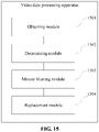
- FIG. 15 is a schematic structural diagram of a video data processing apparatus according to an embodiment of the present disclosure.
- the apparatus includes:
- the determining module 1502 includes:
- the first determining unit includes:
- the detection subunit includes:
- connection point determining subunit is configured to:
- the region determining subunit is configured to:
- the region movement information includes movement distances and movement directions of at least three corners of the target sub-image.
- the motion blurring module 1503 includes:
- the convolution unit is configured to: for each of the at least three groups of convolution parameters,
- the superimposing unit is configured to:
- the apparatus further includes: a perspective transformation module, configured to perform, based on corner coordinates of the target sub-image included in the each of the multiple video frames of the first video, perspective transformation on a corresponding one of the first video frames of the second video, and perform, based on the multiple first video frames of the second video after the perspective transformation, the operation of performing motion blurring on the multiple first video frames of the second video based on the region movement information of the multiple video frames of the first video.
- a perspective transformation module configured to perform, based on corner coordinates of the target sub-image included in the each of the multiple video frames of the first video, perspective transformation on a corresponding one of the first video frames of the second video, and perform, based on the multiple first video frames of the second video after the perspective transformation, the operation of performing motion blurring on the multiple first video frames of the second video based on the region movement information of the multiple video frames of the first video.
- the perspective transformation module is configured to:
- the position movement status of the target sub-image in the first video is obtained based on an artificial intelligence technology.
- motion blurring is performed on the picture of the second video correspondingly, so that the second video and the first video have the same motion blur effect. Therefore, the first video and the second video can be better fused, and a better video transition effect can be obtained.
- the video data processing apparatus processes video data
- division of the foregoing functional modules is merely an example for description.
- the foregoing functions may be assigned to and completed by different modules as needed, that is, the internal structure of the apparatus is divided into different functional modules to implement all or some of the functions described above.
- the video data processing apparatus belongs to the same concept as the embodiments of the video data processing method. For a specific implementation process of the apparatus, reference may be made to the method embodiment, and details are not described herein again.
- the video data processing method described above is performed by a computer device, where the computer device may be a terminal or a server.
- the computer device may be a terminal or a server.
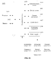
- the method may be implemented by a terminal shown in FIG. 16 below.
- FIG. 16 is a schematic structural diagram of a terminal according to an embodiment of the present disclosure.
- the terminal 1600 may be a smartphone, a tablet computer, a Moving Picture Experts Group Audio Layer III (MP3) player, a Moving Picture Experts Group Audio Layer IV (MP4) player, a notebook computer, or a desktop computer.
- MP3 Moving Picture Experts Group Audio Layer III
- MP4 Moving Picture Experts Group Audio Layer IV
- the terminal 1600 may also be referred to another name such as user equipment, a portable terminal, a laptop terminal, or a desktop terminal.
- the terminal 1600 includes one or more processors 1601 and one or more memories 1602.
- the processor 1601 may include one or more processing cores, for example, a 4-core processor or an 8-core processor.
- the processor 1601 may be implemented in at least one hardware form of a digital signal processor (DSP), a field-programmable gate array (FPGA), or a programmable logic array (PLA).
- DSP digital signal processor
- FPGA field-programmable gate array
- PDA programmable logic array
- the processor 1601 may alternatively include a main processor and a coprocessor.
- the main processor is configured to process data in an awake state, also referred to as a central processing unit (CPU).
- the coprocessor is a low-power processor configured to process data in a standby state.
- the processor 1601 may be integrated with a graphics processing unit (GPU).
- the GPU is configured to render and draw content that needs to be displayed on a display screen.
- the processor 1601 may further include an artificial intelligence (AI) processor.
- the AI processor is configured to process a computing operation related to machine learning.
- the memory 1602 may include one or more computer-readable storage media.
- the computer-readable storage media may be non-transient.
- the memory 1602 may further include a high-speed random access memory and a non-volatile memory, for example, one or more disk storage devices or flash memory devices.
- a non-transient computer-readable storage medium in the memory 1602 is configured to store at least one program code, and the at least one program code is configured to be executed by the processor 1601 to implement the video data processing method according to the method embodiments of the present disclosure.
- the terminal 1600 may optionally include: a peripheral interface 1603 and at least one peripheral.
- the processor 1601, the memory 1602, and the peripheral interface 1603 may be connected through a bus or a signal cable.
- Each peripheral may be connected to the peripheral interface 1603 through a bus, a signal cable, or a circuit board.
- the peripheral includes: at least one of a radio frequency circuit 1604, a display screen 1605, a camera component 1606, an audio circuit 1607, a positioning component 1608, and a power supply 1609.
- the peripheral interface 1603 may be configured to connect the at least one peripheral related to input/output (I/O) to the processor 1601 and the memory 1602.
- the processor 1601, the memory 1602, and the peripheral interface 1603 are integrated on the same chip or the same circuit board.
- any or two of the processor 1601, the memory 1602, and the peripheral interface 1603 may be implemented on an independent chip or circuit board. This is not limited in the embodiments.
- the radio frequency circuit 1604 is configured to receive and transmit a radio frequency (RF) signal, which is also referred to as an electromagnetic signal.
- the radio frequency circuit 1604 communicates with a communication network and other communication devices through the electromagnetic signal.
- the radio frequency circuit 1604 converts an electric signal into an electromagnetic signal for transmission, or converts a received electromagnetic signal into an electric signal.
- the radio frequency circuit 1604 includes: an antenna system, an RF transceiver, one or more amplifiers, a tuner, an oscillator, a digital signal processor, a codec chip set, a subscriber identity module card, and the like.
- the radio frequency circuit 1604 may communicate with another terminal by using at least one wireless communication protocol.
- the wireless communication protocol includes, but is not limited to, a metropolitan area network, different generations of mobile communication networks (2G, 3G, 4G, and 5G), a wireless local area network, and/or a wireless fidelity (Wi-Fi) network.
- the radio frequency circuit 1604 may further include a circuit related to near field communication (NFC). This is not limited in the present disclosure.
- the display screen 1605 is configured to display a user interface (UI).
- the UI may include graphics, text, icons, videos, and any combination thereof.
- the display screen 1605 is further capable of acquiring touch signals on or above a surface of the display screen 1605.
- the touch signal may be used as a control signal to be inputted to the processor 1601 for processing.
- the display screen 1605 may be further configured to provide a virtual button and/or a virtual keyboard that are/is also referred to as a soft button and/or a soft keyboard.
- the display screen 1605 may be a flexible display screen disposed on a curved surface or a folded surface of the terminal 1600. Even, the display screen 1605 may be further configured to have a non-rectangular irregular graph, that is, a special-shaped screen.
- the display screen 1605 may be manufactured by using a material such as a liquid crystal display (LCD) or an organic light-emitting diode (OLED).
- the camera component 1606 is configured to acquire an image or a video.
- the camera component 1606 includes a front-facing camera and a rear-facing camera.
- the front-facing camera is disposed on the front panel of the terminal
- the rear-facing camera is disposed on a back surface of the terminal.
- there are at least two rear cameras which are respectively any of a main camera, a depth-of-field camera, a wide-angle camera, and a telephoto camera, to implement background blur through fusion of the main camera and the depth-of-field camera, panoramic photographing and virtual reality (VR) photographing through fusion of the main camera and the wide-angle camera, or other fusion photographing functions.
- VR virtual reality
- the camera component 1606 may further include a flash.
- the flash may be a single color temperature flash or a double color temperature flash.
- the double color temperature flash refers to a combination of a warm light flash and a cold light flash, and may be used for light compensation under different color temperatures.
- the audio circuit 1607 may include a microphone and a speaker.
- the microphone is configured to acquire sound waves of a user and an environment, and convert the sound waves into electrical signals and input the electrical signals into the processor 1601 for processing, or input the electrical signals into the radio frequency circuit 1604 to implement speech communication. For a purpose of stereo collection or noise reduction, there may be multiple microphones disposed at different portions of the terminal 1600 respectively.
- the microphone may be alternatively an array microphone or an omni-directional collection type microphone.
- the speaker is configured to convert electrical signals from the processor 1601 or the radio frequency circuit 1604 into sound waves.
- the speaker may be a conventional film speaker, or may be a piezoelectric ceramic speaker.
- the speaker When the speaker is the piezoelectric ceramic speaker, the speaker not only can convert an electric signal into acoustic waves audible to a human being, but also can convert an electric signal into acoustic waves inaudible to a human being, for ranging and other purposes.
- the audio circuit 1607 may further include an earphone jack.
- the positioning component 1608 is configured to determine a current geographic location of the terminal 1600, to implement a navigation or a location based service (LBS).
- the positioning component 1608 may be a positioning component based on the global positioning system (GPS) of the United States, a the BeiDou Navigation Satellite System (BDS) of China, the GLONASS System of Russia, or the GALILEO System of the European Union.
- GPS global positioning system
- BDS BeiDou Navigation Satellite System
- GLONASS System GLONASS System of Russia
- GALILEO System of the European Union.
- the power supply 1609 is configured to supply power to components in the terminal 1600.
- the power supply 1609 may be an alternating current, a direct current, a primary battery, or a rechargeable battery.
- the rechargeable battery may be a wired rechargeable battery or a wireless rechargeable battery.
- the rechargeable battery may be further configured to support a fast charge technology.
- the terminal 1600 further includes one or more sensors 1610.
- the one or more sensors 1610 include, but are not limited to, an acceleration sensor 1611, a gyroscope sensor 1612, a pressure sensor 1613, a fingerprint sensor 1614, an optical sensor 1615, and a proximity sensor 1616.
- the acceleration sensor 1611 may detect the magnitude of acceleration on three coordinate axes of a coordinate system established with the terminal 1600.
- the acceleration sensor 1611 may be configured to detect a component of gravity acceleration on the three coordinate axes.
- the processor 1601 may control, according to a gravity acceleration signal acquired by the acceleration sensor 1611, the display screen 1605 to display the user interface in a frame view or a portrait view.
- the acceleration sensor 1611 may be further configured to acquire motion data of a game or a user.
- the gyroscope sensor 1612 may detect a body direction and a rotation angle of the terminal 1600.
- the gyroscope sensor 1612 may cooperate with the acceleration sensor 1611 to acquire a 3D action by the user on the terminal 1600.
- the processor 1601 may implement the following functions according to the data acquired by the gyroscope sensor 1612: motion sensing (such as changing the UI according to a tilt operation of the user), image stabilization during shooting, game control, and inertial navigation.
- the pressure sensor 1613 may be disposed at a side frame of the terminal 1600 and/or a lower layer of the display screen 1605.
- a holding signal of the user on the terminal 1600 may be detected.
- the processor 1601 performs left and right hand recognition or a quick operation according to the holding signal acquired by the pressure sensor 1613.
- the processor 1601 controls, according to a pressure operation of the user on the display screen 1605, an operable control on the UI.
- the operable control includes at least one of a button control, a scroll-bar control, an icon control, and a menu control.
- the fingerprint sensor 1614 is configured to acquire a fingerprint of a user, and the processor 1601 recognizes an identity of the user according to the fingerprint acquired by the fingerprint sensor 1614, or the fingerprint sensor 1614 recognizes the identity of the user according to the acquired fingerprint. When identifying that the identity of the user is a trusted identity, the processor 1601 authorizes the user to perform related sensitive operations.
- the sensitive operations include: unlocking a screen, viewing encryption information, downloading software, paying and changing a setting, and the like.
- the fingerprint sensor 1614 may be disposed on a front surface, a back surface, or a side surface of the terminal 1600. When a physical button or a vendor logo is disposed on the terminal 1600, the fingerprint 1614 may be integrated with the physical button or the vendor logo.
- the optical sensor 1615 is configured to acquire ambient light intensity.
- the processor 1601 may control display brightness of the display screen 1605 according to the ambient light intensity collected by the optical sensor 1615. Specifically, when the ambient light intensity is relatively high, the display brightness of the display screen 1605 is increased; and when the ambient light intensity is relatively low, the display brightness of the display screen 1605 is reduced.
- the processor 1601 may further dynamically adjust a camera parameter of the camera component 1606 according to the ambient light intensity collected by the optical sensor 1615.
- the proximity sensor 1616 also referred to as a distance sensor, is usually disposed on a front panel of the terminal 1600.
- the proximity sensor 1616 is configured to acquire a distance between a user and the front surface of the terminal 1600.
- the processor 1601 controls the display screen 1605 to be switched from a bright screen state to a rest screen state; and when the proximity sensor 1616 detects the distance between the user and the front surface of the terminal 1600 is gradually increased, the processor 1601 controls the touch display screen 1605 to be switched from the rest screen state to the bright screen state.
- FIG. 16 constitutes no limitation on the terminal 1600, and the terminal may include more or fewer components than those shown in the figure, or combine some components, or use a different component deployment.
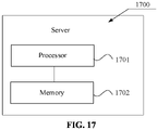
- the server may be implemented by a server shown in FIG. 17 below.
- FIG. 17 is a schematic structural diagram of a server according to an embodiment of the present disclosure.
- the server 1700 may vary greatly because a configuration or performance varies, and may include one or more central processing units (CPU) 1701 and one or more memories 1702.
- the one or more memories 1702 store at least one program code, and the at least one program code is loaded and executed by the one or more processors 1701 to implement the methods according to the foregoing various method embodiments.
- the server 1700 may also have a wired or wireless network interface, a keyboard, an input/output interface and other components to facilitate input/output.
- the server 1700 may also include other components for implementing device functions. Details are not described herein.
- a computer-readable storage medium for example, a memory including at least one program code is further provided.
- the at least one program code may be executed by a processor to implement the video data processing method in the foregoing embodiments.
- the computer-readable storage medium may be a read-only memory (ROM), a random access memory (RAM), a compact disc ROM (CD-ROM), a magnetic tape, a floppy disk, or an optical data storage device.
- a computer program product including at least one program code, the at least one program code being stored in a computer-readable storage medium.
- a processor of a computer device reads the at least one program code from the computer-readable storage medium, and executes the computer instructions, to cause the computer device to implement the operations performed in the video data processing method.
- a person of ordinary skill in the art may understand that all or some of the steps of the foregoing embodiments may be implemented by using hardware, or may be implemented by at least one program code of a program instructing relevant hardware.
- the program may be stored in a computer-readable storage medium.
- the above-mentioned storage medium may be a ROM, a magnetic disk, an optical disc, or the like.
Landscapes
- Engineering & Computer Science (AREA)
- Physics & Mathematics (AREA)
- General Physics & Mathematics (AREA)
- Theoretical Computer Science (AREA)
- Multimedia (AREA)
- Computer Vision & Pattern Recognition (AREA)
- Computational Linguistics (AREA)
- Software Systems (AREA)
- Signal Processing (AREA)
- Image Analysis (AREA)
Applications Claiming Priority (2)
| Application Number | Priority Date | Filing Date | Title |
|---|---|---|---|
| CN202010880221.8A CN112749613B (zh) | 2020-08-27 | 2020-08-27 | 视频数据处理方法、装置、计算机设备及存储介质 |
| PCT/CN2021/113566 WO2022042425A1 (zh) | 2020-08-27 | 2021-08-19 | 视频数据处理方法、装置、计算机设备及存储介质 |
Publications (2)
| Publication Number | Publication Date |
|---|---|
| EP4109330A1 true EP4109330A1 (de) | 2022-12-28 |
| EP4109330A4 EP4109330A4 (de) | 2023-07-05 |
Family
ID=75645360
Family Applications (1)
| Application Number | Title | Priority Date | Filing Date |
|---|---|---|---|
| EP21860263.9A Pending EP4109330A4 (de) | 2020-08-27 | 2021-08-19 | Videodatenverarbeitungsverfahren und -vorrichtung sowie computervorrichtung und speichermedium |
Country Status (4)
| Country | Link |
|---|---|
| US (1) | US20220383511A1 (de) |
| EP (1) | EP4109330A4 (de) |
| CN (1) | CN112749613B (de) |
| WO (1) | WO2022042425A1 (de) |
Families Citing this family (5)
| Publication number | Priority date | Publication date | Assignee | Title |
|---|---|---|---|---|
| CN112749613B (zh) * | 2020-08-27 | 2024-03-26 | 腾讯科技(深圳)有限公司 | 视频数据处理方法、装置、计算机设备及存储介质 |
| USD983819S1 (en) * | 2021-03-26 | 2023-04-18 | Beijing Xiaomi Mobile Software Co., Ltd. | Display screen or portion thereof with graphical user interface |
| CN113449645B (zh) * | 2021-06-29 | 2023-09-22 | 杭州海康威视系统技术有限公司 | 人员出入数据的确定方法、装置、设备及存储介质 |
| CN113345062B (zh) * | 2021-08-04 | 2021-11-05 | 成都市谛视科技有限公司 | 三维虚拟角色动作补全方法、装置和服务器 |
| CN114630057B (zh) * | 2022-03-11 | 2024-01-30 | 北京字跳网络技术有限公司 | 确定特效视频的方法、装置、电子设备及存储介质 |
Family Cites Families (15)
| Publication number | Priority date | Publication date | Assignee | Title |
|---|---|---|---|---|
| GB9119964D0 (en) * | 1991-09-18 | 1991-10-30 | Sarnoff David Res Center | Pattern-key video insertion |
| US8218888B2 (en) * | 2008-02-25 | 2012-07-10 | Mitsubishi Electric Corporation | Motion blur detecting apparatus and method, image processing apparatus, and image display apparatus |
| CN102073652A (zh) * | 2009-11-24 | 2011-05-25 | 腾讯科技(深圳)有限公司 | 一种电子相册生成方法及装置和电子相册播放器 |
| US20130176332A1 (en) * | 2012-01-10 | 2013-07-11 | Nokia Corporation | Method and apparatus for image presentation |
| KR101795270B1 (ko) * | 2016-06-09 | 2017-11-07 | 현대자동차주식회사 | 장애물의 지면경계 정보를 이용한 물체 측면 검출 방법 및 장치 |
| CN107566756B (zh) * | 2017-08-03 | 2020-03-24 | 广东小天才科技有限公司 | 一种视频转场的处理方法及终端设备 |
| JP2019057836A (ja) * | 2017-09-21 | 2019-04-11 | キヤノン株式会社 | 映像処理装置、映像処理方法、コンピュータプログラム、及び記憶媒体 |
| US10482610B2 (en) * | 2017-11-01 | 2019-11-19 | Adobe Inc. | Detection of partially motion-blurred video frames |
| JP7010122B2 (ja) * | 2018-04-11 | 2022-01-26 | 日本電信電話株式会社 | 映像生成装置、映像生成方法、およびプログラム |
| WO2020019164A1 (zh) * | 2018-07-24 | 2020-01-30 | 深圳市大疆创新科技有限公司 | 视频处理方法、设备、计算机可读存储介质 |
| DE102019121570A1 (de) * | 2018-08-13 | 2020-02-13 | Nvidia Corporation | Bewegungsunschärfe- und schärfentiefe-rekonstruktion durch zeitlich stabile neuronale netzwerke |
| CN109671097B (zh) * | 2018-12-12 | 2020-11-13 | 北京像素软件科技股份有限公司 | 运动模糊实现方法及装置 |
| CN111464716B (zh) * | 2020-04-09 | 2022-08-19 | 腾讯科技(深圳)有限公司 | 一种证件扫描方法、装置、设备及存储介质 |
| CN111556336B (zh) * | 2020-05-12 | 2023-07-14 | 腾讯科技(深圳)有限公司 | 一种多媒体文件处理方法、装置、终端设备及介质 |
| CN112749613B (zh) * | 2020-08-27 | 2024-03-26 | 腾讯科技(深圳)有限公司 | 视频数据处理方法、装置、计算机设备及存储介质 |
-
2020
- 2020-08-27 CN CN202010880221.8A patent/CN112749613B/zh active Active
-
2021
- 2021-08-19 WO PCT/CN2021/113566 patent/WO2022042425A1/zh unknown
- 2021-08-19 EP EP21860263.9A patent/EP4109330A4/de active Pending
-
2022
- 2022-08-05 US US17/882,479 patent/US20220383511A1/en active Pending
Also Published As
| Publication number | Publication date |
|---|---|
| CN112749613A (zh) | 2021-05-04 |
| WO2022042425A1 (zh) | 2022-03-03 |
| US20220383511A1 (en) | 2022-12-01 |
| EP4109330A4 (de) | 2023-07-05 |
| CN112749613B (zh) | 2024-03-26 |
Similar Documents
| Publication | Publication Date | Title |
|---|---|---|
| US11205282B2 (en) | Relocalization method and apparatus in camera pose tracking process and storage medium | |
| EP3985990A1 (de) | Verfahren und gerät zur positionierung von videoclips, computervorrichtung und speichermedium | |
| US11798278B2 (en) | Method, apparatus, and storage medium for classifying multimedia resource | |
| EP4109330A1 (de) | Videodatenverarbeitungsverfahren und -vorrichtung sowie computervorrichtung und speichermedium | |
| CN111091132B (zh) | 基于人工智能的图像识别方法、装置、计算机设备及介质 | |
| US20220004794A1 (en) | Character recognition method and apparatus, computer device, and storage medium | |
| CN110059685B (zh) | 文字区域检测方法、装置及存储介质 | |
| US11978219B2 (en) | Method and device for determining motion information of image feature point, and task performing method and device | |
| CN111931877B (zh) | 目标检测方法、装置、设备及存储介质 | |
| CN110807361A (zh) | 人体识别方法、装置、计算机设备及存储介质 | |
| CN113076814B (zh) | 文本区域的确定方法、装置、设备及可读存储介质 | |
| CN110570460A (zh) | 目标跟踪方法、装置、计算机设备及计算机可读存储介质 | |
| CN111258467A (zh) | 界面显示方法、装置、计算机设备及存储介质 | |
| US11908105B2 (en) | Image inpainting method, apparatus and device, and storage medium | |
| CN114170349A (zh) | 图像生成方法、装置、电子设备及存储介质 | |
| CN110647881A (zh) | 确定图像对应的卡片类型的方法、装置、设备及存储介质 | |
| CN111738914A (zh) | 图像处理方法、装置、计算机设备及存储介质 | |
| CN112230908A (zh) | 一种对齐组件的方法、装置、电子设备及存储介质 | |
| CN111105474B (zh) | 字体绘制方法、装置、计算机设备及计算机可读存储介质 | |
| CN111325220A (zh) | 图像生成方法、装置、设备及存储介质 | |
| CN112396076A (zh) | 车牌图像生成方法、装置及计算机存储介质 | |
| CN112053360B (zh) | 图像分割方法、装置、计算机设备及存储介质 | |
| CN112163062B (zh) | 数据处理方法、装置、计算机设备及存储介质 | |
| CN110335224B (zh) | 图像处理方法、装置、计算机设备及存储介质 | |
| CN114925667A (zh) | 内容分类方法、装置、设备及计算机可读存储介质 |
Legal Events
| Date | Code | Title | Description |
|---|---|---|---|
| STAA | Information on the status of an ep patent application or granted ep patent |
Free format text: STATUS: THE INTERNATIONAL PUBLICATION HAS BEEN MADE |
|
| PUAI | Public reference made under article 153(3) epc to a published international application that has entered the european phase |
Free format text: ORIGINAL CODE: 0009012 |
|
| STAA | Information on the status of an ep patent application or granted ep patent |
Free format text: STATUS: REQUEST FOR EXAMINATION WAS MADE |
|
| 17P | Request for examination filed |
Effective date: 20220919 |
|
| AK | Designated contracting states |
Kind code of ref document: A1 Designated state(s): AL AT BE BG CH CY CZ DE DK EE ES FI FR GB GR HR HU IE IS IT LI LT LU LV MC MK MT NL NO PL PT RO RS SE SI SK SM TR |
|
| REG | Reference to a national code |
Ref country code: DE Ref legal event code: R079 Free format text: PREVIOUS MAIN CLASS: G06K0009000000 Ipc: G06V0020400000 |
|
| A4 | Supplementary search report drawn up and despatched |
Effective date: 20230607 |
|
| RIC1 | Information provided on ipc code assigned before grant |
Ipc: H04N 5/265 20060101ALI20230601BHEP Ipc: G06V 10/44 20220101ALI20230601BHEP Ipc: G06T 7/246 20170101ALI20230601BHEP Ipc: G06T 5/00 20060101ALI20230601BHEP Ipc: G06V 20/40 20220101AFI20230601BHEP |