EP4109028A1 - Radiant tube - Google Patents
Radiant tube Download PDFInfo
- Publication number
- EP4109028A1 EP4109028A1 EP21757979.6A EP21757979A EP4109028A1 EP 4109028 A1 EP4109028 A1 EP 4109028A1 EP 21757979 A EP21757979 A EP 21757979A EP 4109028 A1 EP4109028 A1 EP 4109028A1
- Authority
- EP
- European Patent Office
- Prior art keywords
- conduit
- heat transfer
- protruding parts
- protruding
- radiant tube
- Prior art date
- Legal status (The legal status is an assumption and is not a legal conclusion. Google has not performed a legal analysis and makes no representation as to the accuracy of the status listed.)
- Granted
Links
Images



Classifications
-
- F—MECHANICAL ENGINEERING; LIGHTING; HEATING; WEAPONS; BLASTING
- F23—COMBUSTION APPARATUS; COMBUSTION PROCESSES
- F23C—METHODS OR APPARATUS FOR COMBUSTION USING FLUID FUEL OR SOLID FUEL SUSPENDED IN A CARRIER GAS OR AIR
- F23C3/00—Combustion apparatus characterised by the shape of the combustion chamber
- F23C3/002—Combustion apparatus characterised by the shape of the combustion chamber the chamber having an elongated tubular form, e.g. for a radiant tube
-
- F—MECHANICAL ENGINEERING; LIGHTING; HEATING; WEAPONS; BLASTING
- F23—COMBUSTION APPARATUS; COMBUSTION PROCESSES
- F23C—METHODS OR APPARATUS FOR COMBUSTION USING FLUID FUEL OR SOLID FUEL SUSPENDED IN A CARRIER GAS OR AIR
- F23C3/00—Combustion apparatus characterised by the shape of the combustion chamber
-
- F—MECHANICAL ENGINEERING; LIGHTING; HEATING; WEAPONS; BLASTING
- F23—COMBUSTION APPARATUS; COMBUSTION PROCESSES
- F23D—BURNERS
- F23D14/00—Burners for combustion of a gas, e.g. of a gas stored under pressure as a liquid
- F23D14/12—Radiant burners
-
- F—MECHANICAL ENGINEERING; LIGHTING; HEATING; WEAPONS; BLASTING
- F23—COMBUSTION APPARATUS; COMBUSTION PROCESSES
- F23J—REMOVAL OR TREATMENT OF COMBUSTION PRODUCTS OR COMBUSTION RESIDUES; FLUES
- F23J15/00—Arrangements of devices for treating smoke or fumes
- F23J15/06—Arrangements of devices for treating smoke or fumes of coolers
-
- F—MECHANICAL ENGINEERING; LIGHTING; HEATING; WEAPONS; BLASTING
- F23—COMBUSTION APPARATUS; COMBUSTION PROCESSES
- F23M—CASINGS, LININGS, WALLS OR DOORS SPECIALLY ADAPTED FOR COMBUSTION CHAMBERS, e.g. FIREBRIDGES; DEVICES FOR DEFLECTING AIR, FLAMES OR COMBUSTION PRODUCTS IN COMBUSTION CHAMBERS; SAFETY ARRANGEMENTS SPECIALLY ADAPTED FOR COMBUSTION APPARATUS; DETAILS OF COMBUSTION CHAMBERS, NOT OTHERWISE PROVIDED FOR
- F23M9/00—Baffles or deflectors for air or combustion products; Flame shields
- F23M9/003—Baffles or deflectors for air or combustion products; Flame shields in flue gas ducts
-
- F—MECHANICAL ENGINEERING; LIGHTING; HEATING; WEAPONS; BLASTING
- F28—HEAT EXCHANGE IN GENERAL
- F28F—DETAILS OF HEAT-EXCHANGE AND HEAT-TRANSFER APPARATUS, OF GENERAL APPLICATION
- F28F13/00—Arrangements for modifying heat-transfer, e.g. increasing, decreasing
- F28F13/06—Arrangements for modifying heat-transfer, e.g. increasing, decreasing by affecting the pattern of flow of the heat-exchange media
- F28F13/12—Arrangements for modifying heat-transfer, e.g. increasing, decreasing by affecting the pattern of flow of the heat-exchange media by creating turbulence, e.g. by stirring, by increasing the force of circulation
-
- F—MECHANICAL ENGINEERING; LIGHTING; HEATING; WEAPONS; BLASTING
- F24—HEATING; RANGES; VENTILATING
- F24H—FLUID HEATERS, e.g. WATER OR AIR HEATERS, HAVING HEAT-GENERATING MEANS, e.g. HEAT PUMPS, IN GENERAL
- F24H9/00—Details
- F24H9/0052—Details for air heaters
- F24H9/0057—Guiding means
- F24H9/0068—Guiding means in combustion gas channels
Definitions
- the present invention relates to a radiant tube that includes a heat transfer promoter.
- the radiant tube includes a conduit forming a tube body, and a gas generating part such as a burner that is disposed on the inlet side of the conduit and generates a combustion gas.
- the radiant tube indirectly heats an object to be heated that is present outside the conduit, by the radiant heat from the conduit heated by the combustion gas generated by the gas generating part.
- the combustion gas generated by the gas generating part flows along a gas flow passage formed by the conduit. Consequently, the conduit is in a high temperature state due to the heat transfer from the combustion gas.
- the radiant tube on the outlet side (the downstream side) of the conduit where the heat transfer from the combustion gas to the conduit proceeds so that the temperature of the combustion gas is lowered, the amount of radiant heat transfer is reduced so that the surface temperature of the conduit is lowered. Therefore, there are cases where, in order to enhance the heat transfer efficiency from the combustion gas to the conduit on the downstream side (the outlet side) of the conduit of the radiant tube to increase the heat utilization rate of the radiant tube, a heat transfer promoter is disposed on the downstream side of the conduit.
- PTL 1 discloses a configuration in which a heat transfer promoter is disposed in the latter half of a conduit of a radiant tube, and as the heat transfer promoter, a plate-shaped guide vane is provided that forms the flow passage of a combustion gas into a spiral shape.
- the combustion gas is made to flow to the outlet of the conduit while spirally swirling in the latter half of the conduit of the radiant tube, thereby increasing the relative velocity between the conduit and the combustion gas to increase the convective heat transfer coefficient.
- PTL 2 discloses that there is provided a plurality of heat transfer promoters each having four plate-shaped partitions and a cruciform cross section and that the cruciform-cross-section heat transfer promoters are fitted in series in a conduit with a phase difference of 45 degrees.
- PTL 3 proposes a star-shaped heat transfer promoter that can be manufactured inexpensively, wherein the ratio of the cross-sectional area of the heat transfer promoter to the cross-sectional area of a radiant tube, and the ratio of the perimeter of a cross section of the heat transfer promoter to the perimeter of a cross section of the radiant tube are defined to improve the heat transfer efficiency and to suppress an increase in pressure loss due to the insertion of the heat transfer promoter.
- the technology of PTL 3 is aimed at improving the heat transfer coefficient by reducing the flow passage area. With this technology, the gas flow velocity in the flow direction along a conduit is improved. However, with this technology, since distal ends of protruding parts forming the heat transfer promoter are in contact with an inner wall surface of the conduit, cross sections of flow passages formed between the adjacent protruding parts are in a state of being separated from each other so that the flow in the swirling direction is suppressed.
- the heat transfer promoter has a simple shape and can be manufactured inexpensively, but due to the separation of the individual flow passage cross sections, it is not possible to obtain a large heat transfer coefficient correspondingly. Further, in PTL 3, taking into account the operation of an actual radiant tube, the deformation margin in consideration of the thermal deformation of the radiant tube and the heat transfer promoter becomes necessary.
- the present invention has been made in view of the circumstances described above and has an object to provide a radiant tube including a heat transfer promoter that has a simple structure and that is able to further improve the heat transfer efficiency.
- the inventors have performed a numerical simulation about the shape of a heat transfer promoter having a plurality of protruding parts like in PTL 3, wherein the heat transfer efficiencies of radiant tubes are compared with each other based on the waste heat reduction ratios thereof. Further, in this experiment, the inventors have evaluated the pressure loss caused by inserting the heat transfer promoter in a conduit. From the results of this numerical simulation, the present inventors have found that, in order to improve the heat transfer efficiency with the heat transfer promoter having the plurality of protruding parts on the outer periphery, it is effective that the distance (gap ⁇ L) between an inner surface of the conduit of the radiant tube and a distal end of the protruding part of the heat transfer promoter is maintained in a specific ratio.
- the inventors have obtained knowledge that it is preferable to simply dispose the heat transfer promoter in the conduit while forming the gap ⁇ L described above.
- the inventors have obtained knowledge that, with the configuration described above, the pressure loss is small like with the heat transfer promoter described in PTL 3, and further that this heat transfer promoter can be manufactured inexpensively.
- the "heat transfer efficiency" in the present invention refers to the efficiency of, out of heat transferred to a conduit of a radiant tube from a combustion gas and waste heat discharged as sensible heat of an exhaust gas, the heat transferred to the conduit of the radiant tube.
- the waste heat that is discharged without being transferred to the conduit from the exhaust gas is reduced, the heat transfer efficiency is improved.
- the gist of one aspect of the present invention is a radiant tube including: a conduit configured to be heated by a fluid gas flowing in the conduit; and one or two or more heat transfer promoters disposed in the conduit along an axis of the conduit, wherein: the heat transfer promoter includes a body part disposed on a center side of the conduit, and a plurality of protruding parts protruding from the body part toward an inner wall surface of the conduit; the plurality of protruding parts is formed on an outer periphery of the body part to be arranged in a circumferential direction of the conduit; the plurality of protruding parts includes a plurality of first protruding parts each having a distal end portion facing the inner wall surface of the conduit across a gap ⁇ L, and a second protruding part as a remainder; the number of first protruding parts is set to be greater than the number of second protruding parts; and when a ratio ( ⁇ L/Dt) of the gap
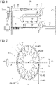
- a radiant tube 100 of this embodiment includes a conduit 1 in which a combustion gas (hereinafter also referred to simply as a gas) flows, a radiant tube burner 2 that generates a combustion gas in the conduit 1, and a heat transfer promoter 4.
- the radiant tube 100 may include a waste heat recovery device 5 such as a recuperator or a regenerative burner, or another known component, or may be configured not to include such a component.
- the recuperator is a device that performs heat exchange between a combustion gas flowing in the radiant tube 100 and combustion air.
- This embodiment exemplifies the case where a plurality of heat transfer promoters 4 is coaxially aligned with each other, and protruding parts 42 of the plurality of heat transfer promoters 4 are aligned with each other along the conduit.
- the conduit 1 of this embodiment has a generally W-shaped winding shape in side view. That is, the conduit 1 includes four straight pipe parts 1A to 1D vertically arranged side by side, and end portions of the adjacent straight pipe parts 1A to 1D are joined together by curved pipe parts 1E to 1G each extending in an arc shape, thereby forming a flow passage of a gas.
- the reference numeral 6 denotes a separator member that prevents narrowing between the adjacent straight pipe parts.
- the reference numeral 7 denotes a support member that is supported by an overhanging part 3A to prevent the downward displacement of the conduit 1.
- the inlet side of the straight pipe part 1A at the most upstream position and the outlet side of the straight pipe part 1D at the most downstream position are fixed to a furnace wall 3 so that the conduit 1 is supported by the furnace wall 3.
- FIG. 2 illustrates an example of the conveying direction of the object to be heated by the reference numeral 50.
- FIG. 1 exemplifies the case where the arrangement direction of the plurality of straight pipe parts 1A to 1D is the up-down direction, but the arrangement direction of the plurality of straight pipe parts 1A to 1D may be the left-right direction.
- the conduit shape of the radiant tube 100 is not limited to the generally W-shape in side view.
- the conduit shape of the radiant tube 100 may be another shape such as, for example, a U-type shape or a straight-type shape.
- an opening cross section of at least the straight pipe part 1D where the heat transfer promoters 4 are disposed has, as illustrated in FIG. 2 , an oval shape with the short diameter and the long diameter different from each other. It is preferable that the long diameter side be directed in the up-down direction as illustrated in FIG. 2 .
- the opening cross section of the straight pipe part 1D has the oval shape with the short diameter and the long diameter different from each other
- the conduit 1 in its entirety have the oval shape with the short diameter and the long diameter different from each other.
- the present invention is applicable even when the opening cross section of the conduit 1 has another cross-sectional shape such as a perfect circle or a rectangular shape.
- a gas generating part 2A of the radiant tube burner 2 is disposed on the inlet side of the conduit 1.
- the gas generating part 2A ejects a fuel gas and combustion air along the extending direction of the conduit 1 to generate a combustion gas.
- the generated combustion gas transfers the heat to the conduit 1 while flowing from the inlet side toward the outlet side in the conduit 1.
- the gas generating part 2A is not particularly limited as long as it can generate a combustion gas that is made to pass through the inside of the conduit 1, and it is possible to use a known burner.
- the heat transfer promoter 4 is disposed on the outlet side with respect to the intermediate position in the extending direction in the conduit 1 of the radiant tube 100.
- the heat transfer promoter 4 is provided in the conduit 1 for improving the heat transfer efficiency of the radiant tube 100.
- the plurality of heat transfer promoters 4 is coaxially disposed along the axis of the conduit 1.
- the plurality of heat transfer promoters 4 adjusts, as appropriate, the waste heat reduction ratio and the pressure loss of the radiant tube 100.
- Each of the heat transfer promoters 4 includes a body part 41 located on the cross-section center side of the conduit 1 (the axial side of the conduit 1), and the plurality of protruding parts 42 integrated with the body part 41 and protruding from the body part 41 toward an inner wall surface 1a of the conduit 1.
- the plurality of protruding parts 42 is arranged in the circumferential direction of the conduit 1 and integrally formed on the outer periphery of the body part 41.
- the heat transfer promoters 4 are disposed in the conduit 1 in such a way that the protruding parts 42 of the heat transfer promoters 4 are aligned with each other in the longitudinal direction of the conduit 1. It is preferable that the adjacent heat transfer promoters 4 be disposed in contact with each other.
- each of the protruding parts 42 protrudes from the body part 41 toward the radially outer side of the conduit 1, and as viewed in the axial direction of the conduit 1, has a shape such that, as illustrated in FIG. 2 , the width along the circumferential direction of the conduit 1 decreases as away from the body part 41 (as approaching the wall surface of the conduit 1).
- each of the protruding parts 42 is configured such that the shape is the same along the axial direction of the conduit 1.
- a space is formed in which the distance between the adjacent two protruding parts 42 increases as away from the body part 41.
- the contour that defines the cross-sectional shape of the protruding part 42 does not have to be rectilinear.
- the plurality of protruding parts 42 of each heat transfer promoter 4 is classified into a plurality of first protruding parts 42a and a second protruding part 42b.
- a distal end portion of the first protruding part 42a is not in contact with the inner wall surface 1a of the conduit 1, and the distal end portion of the first protruding part 42a is disposed to face the inner wall surface 1a of the conduit 1 across a gap ⁇ L in the radial direction of the conduit 1.
- the second protruding part 42b is in contact with the inner wall surface 1a of the conduit 1 at a distal end portion of the protruding part 42.
- positioning positioning in the direction perpendicular to the axis of the conduit 1) of the heat transfer promoter 4 in the conduit 1 can be performed by the second protruding part 42b.
- the number of second protruding parts 42b is preferably two or more.
- the number of second protruding parts 42b be as small as possible.
- the number of second protruding parts 42b is smaller than the number of first protruding parts 42a.
- the number of second protruding parts 42b is equal to or less than 1/3 of the number of first protruding parts 42a, and more preferably equal to or less than 1/4 of the number of first protruding parts 42a.
- the number of second protruding parts 42b be two or more.
- FIG. 2 exemplifies the case where the number of second protruding parts 42b is two, wherein the heat transfer promoter 4 is supported by its own weight with respect to the conduit 1 by the two second protruding parts 42b located on the lower side.
- the gap ⁇ L between the distal end portion of the first protruding part 42a and the inner wall surface 1a of the conduit 1 facing the distal end portion is defined as follows.
- the gap ⁇ L is set so as to satisfy a formula (1) below. 0.3 % ⁇ x ⁇ 7 %
- each of the heat transfer promoters 4 includes the body part 41 and the plurality of protruding parts 42 protruding from the outer periphery of the body part 41 toward the inner wall surface 1a.
- the body part 41 has a columnar shape with a cross section having a shape similar or approximate to the oval shape of the opening cross section of the conduit 1.
- the body part 41 is disposed in such a way that the axis (longitudinal direction) of the columnar shape is disposed parallel to the axis of the conduit 1.
- the area through which a gas flowing in the conduit 1 passes is limited so that the flow velocity of the gas flowing on the outer peripheral side (the outer diameter side) of the body part 41 increases.
- the gas flowing on the outer periphery of the body part 41 is divided into a plurality of gases along the circumferential direction by the protruding parts 42 so that the gases respectively flow in the spaces between the adjacent protruding parts 42.
- the protruding part 42 of this embodiment has a cross section of a generally triangular shape (triangular shape as viewed in the axial direction of the conduit 1), and the base is integrally formed with the outer periphery of the body part 41. Further, in the longitudinal direction, the protruding part 42 has a thick plate shape with the same cross-sectional shape in the direction parallel to the axis of the conduit 1 (a rectangular shape in side view).
- a space S is formed that has a triangular cross section in which the width increases as away from the body part 41.
- the gas flowing on the outer periphery of the body part 41 is unlikely to form a swirling flow and flows along the axis of the conduit 1 as a laminar flow along the spaces S. That is, by providing the plurality of protruding parts 42, gas flow passages individual to each other are formed between the protruding parts 42 in the circumferential direction so that it is possible to make the gas pass through the respective gas flow passages.
- the second protruding parts 42b are configured by making the two protruding parts 42 on the lower side longer than the other protruding parts 42.
- the heat transfer promoter 4 is supported at a predetermined position in the conduit 1.
- the heat transfer promoter 4 is positioned more stably in the conduit 1.
- the number of second protruding parts 42b is preferably as small as possible.
- the position of the center of gravity P2 of the heat transfer promoter 4 disposed in the conduit 1 be set (disposed) to coincide with the center P1 (the center of gravity) of the opening cross section of the conduit 1 by the plurality of second protruding parts 42b.
- the centers of gravity P1, P2 of both members 1, 4 are disposed to coincide with each other, the center of gravity P2 of the heat transfer promoter 4 and a center-of-gravity portion in a cross section perpendicular to the combustion flow direction of the radiant tube 100 coincide with each other so that it is possible to suppress the offset of the heat transfer promoter 4 to the gravity direction to eliminate a reduction in heat transfer performance.
- the radiant tube shape is oval, it is very effective to make the center of gravity of the heat transfer promoter 4 and the center-of-gravity portion in the cross section perpendicular to the combustion flow direction of the radiant tube 100 coincide with each other.
- the lengths of the first and second protruding parts and the size of the body part 41 are set so that the protruding parts 42 other than the protruding parts 42 forming the second protruding parts 42b form the first protruding parts 42a, and that the gap ⁇ L is formed between the distal end portion of each of the plurality of first protruding parts 42a and the inner surface of the conduit 1.
- the area through which the gas flowing in the conduit 1 passes is limited so that the flow velocity of the gas flowing on the outer peripheral side (the outer diameter side) of the body part 41 increases.
- the center of gravity of the cross section of the body part 41 and the center of gravity of the cross section of the conduit 1 coincide with each other or approximate to each other, the distribution of the gas flowing on the outer periphery of the body part 41 is further equalized.
- the space on the outer periphery of the body part 41 is divided into a plurality of spaces along the circumferential direction of the conduit 1. That is, gas flow passages independent of each other are formed between the adjacent protruding parts 42 so that it is possible to make the gas pass through the respective gas flow passages.
- the heat transfer promoter 4 when the ratio of the cross-sectional area of the heat transfer promoter 4 to the opening cross-sectional area of the conduit 1 portion where the heat transfer promoter 4 is disposed is given by A, and the ratio of the perimeter of the cross section of the heat transfer promoter 4 to the perimeter of the opening cross section of the conduit 1 portion where the heat transfer promoter 4 is disposed is given by B, it is preferable that the heat transfer promoter 4 with respect to the conduit 1 satisfy a formula (3) and a formula (4) below.
- the area of the opening cross section of the installation part of the conduit 1 is given by ⁇ .
- the cross-sectional area of the heat transfer promoter 4 is given by ⁇ .
- A is given by ( ⁇ / ⁇ ).
- the perimeter of the opening cross section of the installation part of the conduit 1 (the inner perimeter of the conduit 1) is given by c.
- the perimeter of the heat transfer promoter 4 is given by d.
- B is given by (d/c).
- the heat transfer promoter 4 of this embodiment is preferably designed so that A and B satisfy the formula (4) and the formula (4) described above.
- A is preferably 0.53 or less as defined by the formula (3). More preferably, A is 0.46 or less.
- the formula (4) described above is a formula discovered by the present inventors by paying attention to the fact that, based on the general convective heat transfer theoretical formula, as the cross-sectional area of the heat transfer promoter 4 decreases, the gas flow velocity decreases so that the effect of convective heat transfer is weakened, and the heat transfer area is proportional to the outer perimeter of the heat transfer promoter 4.
- the present inventors have confirmed that when the left side of the formula (4) is 2.48 or more, the desired heat transfer efficiency can be obtained.
- one of the features is to provide the predetermined gap ⁇ L between the first protruding part 42a and the inner wall surface 1a of the conduit 1.
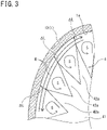
- the flow (swirling flow R) in the swirling direction of the combustion flow along the circumferential direction of the conduit 1 is formed in the vicinity of the inner wall surface of the conduit 1.
- V ⁇ Vx 2 + Vy 2 + Vz 2
- the velocity V is increased corresponding to the swirling flow R formed in the vicinity of the inner wall of the conduit 1, and further, in this embodiment, the heat transfer efficiency is also improved.
- the swirling flow R becomes stronger particularly when the flow transitions from a curved surface to a straight surface.
- the portion where the flow transitions from the curved surface to the straight surface is, for example, a transition part from the curved pipe part 1G to the straight pipe part 1D in FIG. 1 , and stagnation tends to occur in an upper-side space position around the A-A' cross section position in FIG. 1 . This is due to the flow offset generated by the separation of the combustion flow on the curved surface. Therefore, with a heat transfer promoter that provides no gap or a gap less than the gap ⁇ L based on the present invention, different amounts of a combustion gas flow in the divided spaces S, respectively, and as a result, the heat transfer efficiency is reduced.
- the flow rate balance between the plurality of spaces S defined by the protruding parts 42 is spontaneously kept at the same flow rate therebetween.
- the protruding parts 42 that divide the flow of the gas each have a shape in which the width decreases as approaching the inner wall surface 1a of the conduit 1. Therefore, as illustrated in FIG. 3 , the swirling flow tends to occur also in each of the spaces S defined by the protruding parts 42 so that the heat transfer efficiency from the combustion flow to the heat transfer promoter is increased.
- the cross section of each of the spaces S defined by the protruding parts 42 is such that the width increases as approaching the inner wall surface 1a of the conduit 1, and thus the influence of the wall surface is small, resulting in a relatively small flow passage resistance. Therefore, the gas flowing between the protruding parts 42 flows more on the outer peripheral side than on the center side. As a result, more gas contributes to the swirling flow R formed in the vicinity of the inner wall surface 1a of the conduit 1.
- the shape of the protruding part 42 is not a rectangular shape or the like in cross section, but a generally triangular shape in which the width in the circumferential direction is narrowed as approaching the inner wall of the conduit 1. Therefore, further, compared to the case where the shape of the protruding part 42 is rectangular in cross section, the cross section of each of the spaces S defined by the protruding parts 42 is such that the degree of widening in the circumferential direction per unit length can be set to be greater as going radially outward. As a result, the gas flowing between the protruding parts 42 flows further more on the outer peripheral side than on the center side so that more gas contributes to the swirling flow R formed in the vicinity of the inner wall surface 1a of the conduit 1.
- the protruding parts 42 preferably have a shape (a continuous shape) in which roots (portions on the body part side) of the adjacent protruding parts 42 are connected together.
- the heat transfer promoter 4 when the cross section of the space S formed between the protruding parts 42 has a triangular shape, the heat transfer promoter 4, the combustion gas, and the wall surface of the conduit 1 are always aligned with each other so that the radiant heat transfer from the combustion gas as a heat source to the conduit is not impaired.
- a predetermined gap ⁇ L is required between the protruding part 42 of the heat transfer promoter 4 and the inner wall surface 1a of the conduit 1.
- the predetermined gap ⁇ L is a gap equal to or greater than the width of a region, called a viscous sublayer, where the flow velocity of a combustion gas in the vicinity of a wall surface is approximate to zero.
- the region width of a viscous sublayer is 0.3% or more relative to the equivalent diameter, and therefore, when the gap is 0.5% relative to the equivalent diameter, it is fully in a transition region.
- the percentage x of a ratio ( ⁇ L/Dt) of the gap ⁇ L to an equivalent diameter Dt of a conduit 1 portion where the heat transfer promoter 4 is disposed is set to 0.3% or more and preferably 0.5%.
- the above-described x is set to 7% or less and preferably 4.5% or less.
- the heat transfer promoter 4 As a material forming the heat transfer promoter 4, a material known as the heat transfer promoter 4 may be employed.
- a material known as the heat transfer promoter 4 insulating firebrick, refractory metal, ceramic, castable, or the like can be cited by way of example.
- insulating firebrick, refractory metal, ceramic, castable, or the like can be cited by way of example.
- the heat transfer promoter 4 is designed into the specific shape as described above. Consequently, it is possible to reduce the flow passage cross-sectional area and to increase the flow velocity of a combustion gas by the flow passage reduction. Further, in this embodiment, it is possible to enhance the heat transfer efficiency while increasing the heat transfer area of the heat transfer promoter 4 without suppressing the swirling flow R of the combustion gas in the vicinity of the inner wall surface. Further, the heat transfer promoter 4 of this embodiment has the simple shape and thus can be manufactured inexpensively. By inserting the heat transfer promoter 4 into the radiant tube 100, it is possible to stir the combustion gas like the conventional technology.
- the heat transfer promoter 4 having the uniform cross section along the flow passage is used, but by tapering the heat transfer promoter 4 along the flow passage toward the exhaust gas upstream side, it is possible to further promote the stirring of the combustion gas and to further enhance the heat transfer efficiency.
- ⁇ P 1 / 2 f ⁇ 1 / Dt ⁇ ⁇ ⁇ u 2 .
- the range of a viscous sublayer is given by u ⁇ y / ⁇ ⁇ 5 .
- the position, close to the inner wall surface 1a of the conduit 1, in the heat transfer promoter 4 is the distal end of the protruding part.
- the efficiency of the transfer of the heat, transferred from a combustion gas to the heat transfer promoter 4, to the inner wall surface 1a of the conduit 1 from the distal end of the protruding part 42 close to the inner wall surface 1a of the conduit 1, is improved. That is, the heat transfer area of the heat transfer promoter 4 to the conduit 1 is increased so that a further heat transfer promotion effect is exhibited.
- the heat transfer promoter 4 has a cavity inside, and the cavity is open on the surface side along the direction of movement of a fluid flowing in the conduit 1.
- the opening cross section of the conduit 1 portion where the heat transfer promoter 4 is disposed has the oval shape with the lengths of the short diameter and the long diameter different from each other, and the long diameter may be disposed in the up-down direction.
- An atmosphere in which the radiant tube 100 is disposed becomes a high temperature atmosphere so that the heat load is applied to the conduit 1, but in this modification, the rigidity of the conduit 1 is improved so that even when the load of the heat transfer promoter 4 and the heat load are applied to the conduit 1, it is possible to suppress the deformation of the conduit 1. This makes it possible that indirect heating from the radiant tube 100 to an object to be heated is stably performed for a longer time.
- the number of first protruding parts 42a is preferably 8 or more and 25 or less, for example. As the number of protruding parts 42 increases, the number of flow passages formed on the outer periphery of the body part 41 increases so that the adjustment of the flow in the axial direction of the conduit 1 along the circumferential direction becomes easy. However, when it is too many, there is a possibility that the flow passage resistance becomes high, and therefore, 25 or less is preferable.
- first protruding parts 42a be disposed between the adjacent two second protruding parts 42b.
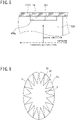
- a cutout 42Ba as illustrated in FIG. 5 may be formed in the distal end of the second protruding part 42b contacting the surface of the conduit 1, at an intermediate position in the longitudinal direction, thereby reducing the suppression of the flow of a swirling flow R due to the second protruding part 42b.
- a facing distance ⁇ L1 to the inner wall surface 1a of the conduit 1 in the cutout 42Ba is set to a value in the same range as the facing condition of the gap ⁇ L with respect to the inner wall surface 1a. That is, it is preferable to perform the setting so as to satisfy a formula equivalent to the formula (1) described above.
- An object to be heated is conveyed along the arrangement direction of the plurality of conduits 1 and indirectly heated by the radiant tube 100.
- the heating efficiency is better when the long diameter is set in the arrangement direction of the conduit 1.
- the area of a space between the protruding parts 42 disposed on the side facing the object to be heated be set to be relatively greater than the area of a space between the protruding parts 42 at another position.
- the inside of the conduit 1 is divided into four regions by two straight lines obtained by inclining the minor axis of the oval shape by ⁇ 45 degrees about the center of the oval shape, and with respect to the areas of spaces between the protruding parts 42 located in the divided regions, the total area of the spaces in the divided region disposed on the side more facing the object to be heated (in the oval shape, the divided region including the minor axis) is set to be relatively greater than the total area of the spaces in the other divided region.
- This embodiment exhibits the following effects.
- the swirling flow R that contributes to the heat transfer can be easily formed in the vicinity of the inner wall surface 1a of the conduit 1 so that the heat transfer efficiency is improved.
- the distal ends of the second protruding parts 42b are in contact with the inner wall surface 1a of the conduit 1, thereby performing the positioning of the heat transfer promoter 4 with respect to the conduit 1.
- the number of second protruding parts 42b is two or more.
- the distal end of the second protruding part 42b does not have to be in contact with the inner wall surface 1a of the conduit 1. In this case, it is not necessary that a gap between the distal end of the second protruding part 42b and the inner wall surface 1a of the conduit 1 satisfy the gap ⁇ L.
- the heat transfer promoter 4 is disposed such that the center of gravity P2 of the heat transfer promoter 4 coincides with the center P1 (the center of gravity) of the opening cross section of the conduit 1.
- the cross-sectional shape of each of the protruding parts 42 is a shape such that the width along the circumferential direction of the conduit 1 decreases as away from the body part 41 in the radial direction of the conduit 1, and, between the two protruding parts 42 adjacent to each other in the circumferential direction of the conduit 1, a space is formed in which the distance between the adjacent two protruding parts 42 increases as away from the body part 41.
- the space in which the distance between the adjacent two protruding parts 42 increases as away from the body part 41 is formed between the two protruding parts 42, and therefore, compared to the case where the protruding part 42 has a plate shape in cross section, the gas flow flows more on the outer peripheral side so that the swirling flow R due to the gap ⁇ L at the distal end of the protruding part 42 is more reliably formed, and as a result, it is possible to further improve the heat transfer efficiency.
- the shape of the distal end portion of the protruding part 42 is a chamfered shape or a curved surface shape.
- the heat transfer promoter 4 has a cavity inside, and the cavity may have a shape in which the surface facing the direction of movement of a fluid flowing in the conduit 1 is closed.
- the opening cross section of the conduit 1 portion where the heat transfer promoter 4 is disposed is oval.
- the short diameter being the shortest diameter
- the long diameter being the diameter perpendicular to the short diameter differ from each other in length. It is preferable that the long diameter of the oval be directed in the up-down direction.
- the rigidity of the conduit 1 is improved so that the deformation of the conduit 1 due to the heat load can be further suppressed, and further, it is possible to further improve the heat transfer efficiency by the heat transfer promoter 4 of this embodiment.
- (long diameter Lb/short diameter La) is set to 1.1 or more and 1.6 or less, for example.
- each of the heat transfer promoters 4 in the longitudinal direction be the same, that the shapes of the plurality of heat transfer promoters 4 be the same, and that the plurality of heat transfer promoters 4 be coaxially disposed with the positions of the distal end portions aligned in the axial direction.
- the swirling flow R can be more reliably generated only in the vicinity of the inner wall surface 1a of the conduit 1, and even with the heat transfer promoters 4 of the simple structure, it is possible to further improve the heat transfer efficiency.
- the heat transfer promoter 4 used in the radiant tube 100 was evaluated by a combustion heat transfer simulation using a finite volume method below.
- the shape of the conduit 1 in the extending direction was the W-shape illustrated in FIG. 1 , and the opening cross section of the conduit 1 had an oval shape with a long diameter of 236 mm and a short diameter of 188 mm.
- the entire length of the conduit 1 was set to 8900 mm.
- a burner was used as the gas generating part 2A.
- a gas generated during carbonization of coal in a coke oven was refined and used.
- Ten heat transfer promoters 4 were disposed in the straight pipe part, located at the most downstream position, from the position of 300 mm to the position of 950 mm on the outlet side of the radiant tube 100.
- the waste heat reduction ratio As the waste heat reduction ratio, the balance between the heat radiation amount from a test furnace and the heat quantity of an exhaust gas was calculated to calculate the ratio of the heat quantity of the exhaust gas accounting for the heat input. Then, the ratios were shown assuming that the waste heat reduction ratio when all protruding parts 42 of a heat transfer promoter 4 of a later-described example 1 were in contact with the inner wall of the radiant tube 100(see FIG. 6 ) was given by 1.00.
- the heat transfer promoter 4 was offset to the gravity direction. That is, this is the case where the position of the center of gravity of the heat transfer promoter 4 is located below the cross-section center of the conduit 1.
- distal ends of protruding parts 42 were chamfered in the shape of the example 1 so that a gap ⁇ L at the distal ends of the protruding parts 42 was made the same as that in the example 3.
- the waste heat reduction amount was approximately equal to the example 4.
- FIG. 10 The study results of the examples 1 to 4 described above are illustrated in FIG. 10 .
- the vertical axis represents the waste heat reduction ratio.
- the waste heat reduction ratio was further improved so that the waste heat reduction ratio was 1.50 or more.
- the waste heat reduction ratio was studied by changing the gap ⁇ L between the distal end portion of the star-shaped heat transfer promoter 4 and the inner wall of the conduit 1.
- the condition was such that the waste heat amount when the distal end portions of the heat transfer promoter 4 were in contact with the wall surface of the conduit 1 was used as a reference, and that the gap ⁇ L between the distal end of the protruding part 42 and the inner wall of the radiant tube 100 to the equivalent diameter of the tube inner wall was the same between the perfect circle and the oval.
- the waste heat reduction ratio is improved similarly regardless of the opening cross section of the conduit 1 being either circular or oval. Further, it has been seen that the waste heat reduction ratio is improved by about 10% when the opening cross section of the conduit 1 is oval compared to when it is circular.
Landscapes
- Engineering & Computer Science (AREA)
- Mechanical Engineering (AREA)
- General Engineering & Computer Science (AREA)
- Chemical & Material Sciences (AREA)
- Combustion & Propulsion (AREA)
- Physics & Mathematics (AREA)
- Thermal Sciences (AREA)
- Heat-Exchange Devices With Radiators And Conduit Assemblies (AREA)
- Combustion Of Fluid Fuel (AREA)
- Air Supply (AREA)
- Vessels And Coating Films For Discharge Lamps (AREA)
Abstract

Description
- The present invention relates to a radiant tube that includes a heat transfer promoter.
- The radiant tube includes a conduit forming a tube body, and a gas generating part such as a burner that is disposed on the inlet side of the conduit and generates a combustion gas. The radiant tube indirectly heats an object to be heated that is present outside the conduit, by the radiant heat from the conduit heated by the combustion gas generated by the gas generating part.
- In the radiant tube, the combustion gas generated by the gas generating part flows along a gas flow passage formed by the conduit. Consequently, the conduit is in a high temperature state due to the heat transfer from the combustion gas. In this event, in the radiant tube, on the outlet side (the downstream side) of the conduit where the heat transfer from the combustion gas to the conduit proceeds so that the temperature of the combustion gas is lowered, the amount of radiant heat transfer is reduced so that the surface temperature of the conduit is lowered. Therefore, there are cases where, in order to enhance the heat transfer efficiency from the combustion gas to the conduit on the downstream side (the outlet side) of the conduit of the radiant tube to increase the heat utilization rate of the radiant tube, a heat transfer promoter is disposed on the downstream side of the conduit.
- For example,
PTL 1 discloses a configuration in which a heat transfer promoter is disposed in the latter half of a conduit of a radiant tube, and as the heat transfer promoter, a plate-shaped guide vane is provided that forms the flow passage of a combustion gas into a spiral shape. With this technology, the combustion gas is made to flow to the outlet of the conduit while spirally swirling in the latter half of the conduit of the radiant tube, thereby increasing the relative velocity between the conduit and the combustion gas to increase the convective heat transfer coefficient. - However, with the method described in
PTL 1, in order to spirally swirl the combustion gas, it is necessary that the structure of the heat transfer promoter should have a complicated shape. Therefore, the manufacturing cost of the heat transfer promoter described inPTL 1 becomes high, and a less expensive heat transfer promoter is required. - On the other hand,
PTL 2 discloses that there is provided a plurality of heat transfer promoters each having four plate-shaped partitions and a cruciform cross section and that the cruciform-cross-section heat transfer promoters are fitted in series in a conduit with a phase difference of 45 degrees. With this configuration, since the configuration is obtained by fitting the plurality of heat transfer promoters in the conduit, it is possible to form a spiral gas flow inexpensively. However, with the cruciform-cross-section heat transfer promoters described inPTL 2, the heat transfer efficiency cannot be said to be sufficiently high, and further improvement is required. - Further,
PTL 3 proposes a star-shaped heat transfer promoter that can be manufactured inexpensively, wherein the ratio of the cross-sectional area of the heat transfer promoter to the cross-sectional area of a radiant tube, and the ratio of the perimeter of a cross section of the heat transfer promoter to the perimeter of a cross section of the radiant tube are defined to improve the heat transfer efficiency and to suppress an increase in pressure loss due to the insertion of the heat transfer promoter. -
- PTL 1:
JP S57-112694 A - PTL 2:
JP S63-173613 U - PTL 3:
JP 2017-83127 A - The technology of
PTL 3 is aimed at improving the heat transfer coefficient by reducing the flow passage area. With this technology, the gas flow velocity in the flow direction along a conduit is improved. However, with this technology, since distal ends of protruding parts forming the heat transfer promoter are in contact with an inner wall surface of the conduit, cross sections of flow passages formed between the adjacent protruding parts are in a state of being separated from each other so that the flow in the swirling direction is suppressed. - That is, in
PTL 3, the heat transfer promoter has a simple shape and can be manufactured inexpensively, but due to the separation of the individual flow passage cross sections, it is not possible to obtain a large heat transfer coefficient correspondingly. Further, inPTL 3, taking into account the operation of an actual radiant tube, the deformation margin in consideration of the thermal deformation of the radiant tube and the heat transfer promoter becomes necessary. - The present invention has been made in view of the circumstances described above and has an object to provide a radiant tube including a heat transfer promoter that has a simple structure and that is able to further improve the heat transfer efficiency.
- The inventors have performed a numerical simulation about the shape of a heat transfer promoter having a plurality of protruding parts like in
PTL 3, wherein the heat transfer efficiencies of radiant tubes are compared with each other based on the waste heat reduction ratios thereof. Further, in this experiment, the inventors have evaluated the pressure loss caused by inserting the heat transfer promoter in a conduit. From the results of this numerical simulation, the present inventors have found that, in order to improve the heat transfer efficiency with the heat transfer promoter having the plurality of protruding parts on the outer periphery, it is effective that the distance (gap ΔL) between an inner surface of the conduit of the radiant tube and a distal end of the protruding part of the heat transfer promoter is maintained in a specific ratio. - Further, the inventors have obtained knowledge that it is preferable to simply dispose the heat transfer promoter in the conduit while forming the gap ΔL described above. The inventors have obtained knowledge that, with the configuration described above, the pressure loss is small like with the heat transfer promoter described in
PTL 3, and further that this heat transfer promoter can be manufactured inexpensively. - Herein, the "heat transfer efficiency" in the present invention refers to the efficiency of, out of heat transferred to a conduit of a radiant tube from a combustion gas and waste heat discharged as sensible heat of an exhaust gas, the heat transferred to the conduit of the radiant tube. When the waste heat that is discharged without being transferred to the conduit from the exhaust gas is reduced, the heat transfer efficiency is improved.
- In order to solve the problems, the gist of one aspect of the present invention is a radiant tube including: a conduit configured to be heated by a fluid gas flowing in the conduit; and one or two or more heat transfer promoters disposed in the conduit along an axis of the conduit, wherein: the heat transfer promoter includes a body part disposed on a center side of the conduit, and a plurality of protruding parts protruding from the body part toward an inner wall surface of the conduit; the plurality of protruding parts is formed on an outer periphery of the body part to be arranged in a circumferential direction of the conduit; the plurality of protruding parts includes a plurality of first protruding parts each having a distal end portion facing the inner wall surface of the conduit across a gap ΔL, and a second protruding part as a remainder; the number of first protruding parts is set to be greater than the number of second protruding parts; and when a ratio (ΔL/Dt) of the gap ΔL to an equivalent diameter Dt of a conduit portion, where the heat transfer promoter is disposed, of the conduit is given by x[%] in percentage, a formula (1) below is satisfied:

- According to the aspect of the present invention, it is possible to provide a radiant tube including a heat transfer promoter that can be manufactured inexpensively while improving the heat transfer efficiency.
-
-
FIG. 1 is a diagram for explaining the structure of a radiant tube according to an embodiment based on the present invention; -
FIG. 2 is a cross-sectional view, taken along A-A' inFIG. 1 , for explaining a cross section of a conduit and a heat transfer promoter of this embodiment; -
FIG. 3 is a schematic diagram as viewed in the axial direction of the conduit for explaining a swirling flow R formed in the vicinity of the inner wall surface; -
FIGS. 4A and 4B are diagrams for explaining an example in which the heat transfer promoter is provided with a cavity, whereinFIG. 4A is a plan view as viewed in the flow direction of a gas, andFIG. 4B is a B-B' cross-sectional view ofFIG. 4A ; -
FIG. 5 is an enlarged view for explaining an example in which a second protruding part is provided with a cutout; -
FIG. 6 is a diagram for explaining a heat transfer promoter of an example 1 (conventional example); -
FIG. 7 is a diagram for explaining a heat transfer promoter of an example 2; -
FIG. 8 is a diagram for explaining a heat transfer promoter of an example 2; -
FIG. 9 is a diagram for explaining a heat transfer promoter of an example 2; -
FIG. 10 is a diagram illustrating the results of verifying the effect of the present invention; -
FIG. 11 is a diagram illustrating the results of verifying the effect of a gap ΔL; and -
FIG. 12 is a diagram illustrating the results of verifying the effect due to the difference in cross section of conduits. - Hereinafter, an embodiment of the present invention will be described with reference to the drawings.
- Herein, the drawings are only exemplary and therefore the ratio of the sizes or lengths of the components, and so on differ from actual ones. Further, the embodiment given below merely exemplifies the configuration for embodying the technical idea of the present invention, and the technical idea of the present invention does not limit the materials, shapes, structures, and so on of the constituent components to those described below. The technical idea of the present invention can be modified in various ways within the technical scope defined by the claims.
- As illustrated in
FIG. 1 , aradiant tube 100 of this embodiment includes aconduit 1 in which a combustion gas (hereinafter also referred to simply as a gas) flows, aradiant tube burner 2 that generates a combustion gas in theconduit 1, and aheat transfer promoter 4. Theradiant tube 100 may include a wasteheat recovery device 5 such as a recuperator or a regenerative burner, or another known component, or may be configured not to include such a component. The recuperator is a device that performs heat exchange between a combustion gas flowing in theradiant tube 100 and combustion air. This embodiment exemplifies the case where a plurality ofheat transfer promoters 4 is coaxially aligned with each other, and protrudingparts 42 of the plurality ofheat transfer promoters 4 are aligned with each other along the conduit. - As illustrated in
FIG. 1 , theconduit 1 of this embodiment has a generally W-shaped winding shape in side view. That is, theconduit 1 includes fourstraight pipe parts 1A to 1D vertically arranged side by side, and end portions of the adjacentstraight pipe parts 1A to 1D are joined together bycurved pipe parts 1E to 1G each extending in an arc shape, thereby forming a flow passage of a gas. The reference numeral 6 denotes a separator member that prevents narrowing between the adjacent straight pipe parts. Thereference numeral 7 denotes a support member that is supported by an overhangingpart 3A to prevent the downward displacement of theconduit 1. - The inlet side of the
straight pipe part 1A at the most upstream position and the outlet side of thestraight pipe part 1D at the most downstream position are fixed to afurnace wall 3 so that theconduit 1 is supported by thefurnace wall 3. - When an object to be heated is conveyed along the arrangement direction of the plurality of
straight pipe parts 1A to 1D, the object to be heated is indirectly heated by theradiant tube 100.FIG. 2 illustrates an example of the conveying direction of the object to be heated by thereference numeral 50.FIG. 1 exemplifies the case where the arrangement direction of the plurality ofstraight pipe parts 1A to 1D is the up-down direction, but the arrangement direction of the plurality ofstraight pipe parts 1A to 1D may be the left-right direction. - Herein, the conduit shape of the
radiant tube 100 is not limited to the generally W-shape in side view. The conduit shape of theradiant tube 100 may be another shape such as, for example, a U-type shape or a straight-type shape. - A description will be made by giving an example in which, in the
conduit 1 of this embodiment, an opening cross section of at least thestraight pipe part 1D where theheat transfer promoters 4 are disposed has, as illustrated inFIG. 2 , an oval shape with the short diameter and the long diameter different from each other. It is preferable that the long diameter side be directed in the up-down direction as illustrated inFIG. 2 . In the case where the opening cross section of thestraight pipe part 1D has the oval shape with the short diameter and the long diameter different from each other, it is preferable that theconduit 1 in its entirety have the oval shape with the short diameter and the long diameter different from each other. Nevertheless, the present invention is applicable even when the opening cross section of theconduit 1 has another cross-sectional shape such as a perfect circle or a rectangular shape. - A
gas generating part 2A of theradiant tube burner 2 is disposed on the inlet side of theconduit 1. Thegas generating part 2A ejects a fuel gas and combustion air along the extending direction of theconduit 1 to generate a combustion gas. The generated combustion gas transfers the heat to theconduit 1 while flowing from the inlet side toward the outlet side in theconduit 1. - The
gas generating part 2A is not particularly limited as long as it can generate a combustion gas that is made to pass through the inside of theconduit 1, and it is possible to use a known burner. - The
heat transfer promoter 4 is disposed on the outlet side with respect to the intermediate position in the extending direction in theconduit 1 of theradiant tube 100. Theheat transfer promoter 4 is provided in theconduit 1 for improving the heat transfer efficiency of theradiant tube 100. - Next, the
heat transfer promoter 4 of this embodiment will be described. - In this embodiment, the plurality of
heat transfer promoters 4 is coaxially disposed along the axis of theconduit 1. The plurality ofheat transfer promoters 4 adjusts, as appropriate, the waste heat reduction ratio and the pressure loss of theradiant tube 100. - Each of the
heat transfer promoters 4 includes abody part 41 located on the cross-section center side of the conduit 1 (the axial side of the conduit 1), and the plurality of protrudingparts 42 integrated with thebody part 41 and protruding from thebody part 41 toward aninner wall surface 1a of theconduit 1. - The plurality of protruding
parts 42 is arranged in the circumferential direction of theconduit 1 and integrally formed on the outer periphery of thebody part 41. Theheat transfer promoters 4 are disposed in theconduit 1 in such a way that the protrudingparts 42 of theheat transfer promoters 4 are aligned with each other in the longitudinal direction of theconduit 1. It is preferable that the adjacentheat transfer promoters 4 be disposed in contact with each other. - Each of the protruding
parts 42 protrudes from thebody part 41 toward the radially outer side of theconduit 1, and as viewed in the axial direction of theconduit 1, has a shape such that, as illustrated inFIG. 2 , the width along the circumferential direction of theconduit 1 decreases as away from the body part 41 (as approaching the wall surface of the conduit 1). On the other hand, each of the protrudingparts 42 is configured such that the shape is the same along the axial direction of theconduit 1. As a result, between every two protrudingparts 42 adjacent to each other in the circumferential direction of theconduit 1, a space is formed in which the distance between the adjacent two protrudingparts 42 increases as away from thebody part 41. The contour that defines the cross-sectional shape of the protrudingpart 42 does not have to be rectilinear. - The plurality of protruding
parts 42 of eachheat transfer promoter 4 is classified into a plurality of first protrudingparts 42a and a secondprotruding part 42b. A distal end portion of the first protrudingpart 42a is not in contact with theinner wall surface 1a of theconduit 1, and the distal end portion of the first protrudingpart 42a is disposed to face theinner wall surface 1a of theconduit 1 across a gap ΔL in the radial direction of theconduit 1. - On the other hand, in this embodiment, the second
protruding part 42b is in contact with theinner wall surface 1a of theconduit 1 at a distal end portion of the protrudingpart 42. In this case, positioning (positioning in the direction perpendicular to the axis of the conduit 1) of theheat transfer promoter 4 in theconduit 1 can be performed by the secondprotruding part 42b. In this case, the number of second protrudingparts 42b is preferably two or more. - On the other hand, if it is possible to perform positioning (positioning in the direction perpendicular to the axis of the conduit 1) of the
heat transfer promoter 4 in theconduit 1 by another means, there is no need to make the secondprotruding part 42b contact theinner wall surface 1a of theconduit 1. - It is preferable that the number of second protruding
parts 42b be as small as possible. In this embodiment, the number of second protrudingparts 42b is smaller than the number of first protrudingparts 42a. Preferably, the number of second protrudingparts 42b is equal to or less than 1/3 of the number of first protrudingparts 42a, and more preferably equal to or less than 1/4 of the number of first protrudingparts 42a. However, in order to perform positioning of theheat transfer promoter 4 in theconduit 1 by the secondprotruding part 42b, it is necessary that the number of second protrudingparts 42b be two or more.FIG. 2 exemplifies the case where the number of second protrudingparts 42b is two, wherein theheat transfer promoter 4 is supported by its own weight with respect to theconduit 1 by the two second protrudingparts 42b located on the lower side. - In this embodiment, the gap ΔL between the distal end portion of the first protruding
part 42a and theinner wall surface 1a of theconduit 1 facing the distal end portion is defined as follows. - That is, when a ratio (ΔL/Dt) of the gap ΔL to an equivalent diameter Dt of the
straight pipe part 1D of theconduit 1 where theheat transfer promoters 4 are disposed is given by x in percentage, the gap ΔL is set so as to satisfy a formula (1) below.
- Further, it is more preferable to satisfy a formula (2) below.

- An example of the
heat transfer promoter 4 of this embodiment will be described. - As described above, each of the
heat transfer promoters 4 includes thebody part 41 and the plurality of protrudingparts 42 protruding from the outer periphery of thebody part 41 toward theinner wall surface 1a. - As illustrated in
FIG. 2 , thebody part 41 has a columnar shape with a cross section having a shape similar or approximate to the oval shape of the opening cross section of theconduit 1. Thebody part 41 is disposed in such a way that the axis (longitudinal direction) of the columnar shape is disposed parallel to the axis of theconduit 1. - With the
body part 41, the area through which a gas flowing in theconduit 1 passes is limited so that the flow velocity of the gas flowing on the outer peripheral side (the outer diameter side) of thebody part 41 increases. - Further, by providing the plurality of protruding
parts 42 on the outer periphery of thebody part 41, the gas flowing on the outer periphery of thebody part 41 is divided into a plurality of gases along the circumferential direction by the protrudingparts 42 so that the gases respectively flow in the spaces between the adjacent protrudingparts 42. - The protruding
part 42 of this embodiment has a cross section of a generally triangular shape (triangular shape as viewed in the axial direction of the conduit 1), and the base is integrally formed with the outer periphery of thebody part 41. Further, in the longitudinal direction, the protrudingpart 42 has a thick plate shape with the same cross-sectional shape in the direction parallel to the axis of the conduit 1 (a rectangular shape in side view). - As illustrated in
FIG. 2 , between the protrudingparts 42 adjacent to each other in the circumferential direction of the conduit 1 (as viewed in the axial direction of the conduit 1), a space S is formed that has a triangular cross section in which the width increases as away from thebody part 41. - With the plurality of protruding
parts 42, the gas flowing on the outer periphery of thebody part 41 is unlikely to form a swirling flow and flows along the axis of theconduit 1 as a laminar flow along the spaces S. That is, by providing the plurality of protrudingparts 42, gas flow passages individual to each other are formed between the protrudingparts 42 in the circumferential direction so that it is possible to make the gas pass through the respective gas flow passages. - In
FIG. 2 , the second protrudingparts 42b are configured by making the two protrudingparts 42 on the lower side longer than the other protrudingparts 42. By the contact of the distal ends of the two protrudingparts 42b with the lower surface side of the inner wall of theconduit 1, theheat transfer promoter 4 is supported at a predetermined position in theconduit 1. When the uppermost protrudingpart 42 is also in contact with the inner wall of theconduit 1 as the secondprotruding part 42b, theheat transfer promoter 4 is positioned more stably in theconduit 1. However, the number of second protrudingparts 42b is preferably as small as possible. - Herein, as illustrated in
FIG. 2 , it is preferable that the position of the center of gravity P2 of theheat transfer promoter 4 disposed in theconduit 1 be set (disposed) to coincide with the center P1 (the center of gravity) of the opening cross section of theconduit 1 by the plurality of second protrudingparts 42b. When the centers of gravity P1, P2 of bothmembers heat transfer promoter 4 and a center-of-gravity portion in a cross section perpendicular to the combustion flow direction of theradiant tube 100 coincide with each other so that it is possible to suppress the offset of theheat transfer promoter 4 to the gravity direction to eliminate a reduction in heat transfer performance. In the case where the radiant tube shape is oval, it is very effective to make the center of gravity of theheat transfer promoter 4 and the center-of-gravity portion in the cross section perpendicular to the combustion flow direction of theradiant tube 100 coincide with each other. - Further, in this embodiment, the lengths of the first and second protruding parts and the size of the
body part 41 are set so that the protrudingparts 42 other than the protrudingparts 42 forming the second protrudingparts 42b form the first protrudingparts 42a, and that the gap ΔL is formed between the distal end portion of each of the plurality of first protrudingparts 42a and the inner surface of theconduit 1. - It is assumed that the gap ΔL satisfies the condition of the formula (1) described above.
- Next, the action of the
heat transfer promoter 4 of this embodiment will be described. - With the
body part 41, the area through which the gas flowing in theconduit 1 passes is limited so that the flow velocity of the gas flowing on the outer peripheral side (the outer diameter side) of thebody part 41 increases. In this embodiment, by making the center of gravity of the cross section of thebody part 41 and the center of gravity of the cross section of theconduit 1 coincide with each other or approximate to each other, the distribution of the gas flowing on the outer periphery of thebody part 41 is further equalized. - Further, with the plurality of protruding
parts 42, the space on the outer periphery of thebody part 41 is divided into a plurality of spaces along the circumferential direction of theconduit 1. That is, gas flow passages independent of each other are formed between the adjacent protrudingparts 42 so that it is possible to make the gas pass through the respective gas flow passages. - Herein, when the ratio of the cross-sectional area of the
heat transfer promoter 4 to the opening cross-sectional area of theconduit 1 portion where theheat transfer promoter 4 is disposed is given by A, and the ratio of the perimeter of the cross section of theheat transfer promoter 4 to the perimeter of the opening cross section of theconduit 1 portion where theheat transfer promoter 4 is disposed is given by B, it is preferable that theheat transfer promoter 4 with respect to theconduit 1 satisfy a formula (3) and a formula (4) below.

- The formula (3) and the formula (4) will be described.
- Herein, the area of the opening cross section of the installation part of the
conduit 1 is given by α. Further, the cross-sectional area of theheat transfer promoter 4 is given by β. Then, A is given by (β/α). Further, the perimeter of the opening cross section of the installation part of the conduit 1 (the inner perimeter of the conduit 1) is given by c. Further, the perimeter of theheat transfer promoter 4 is given by d. Then, B is given by (d/c). - The
heat transfer promoter 4 of this embodiment is preferably designed so that A and B satisfy the formula (4) and the formula (4) described above. As a result of studies by the inventors, it has been found that when A described above exceeds 0.53, the pressure loss is large to significantly suppress the flow of a combustion gas. Therefore, A is preferably 0.53 or less as defined by the formula (3). More preferably, A is 0.46 or less. - The formula (4) described above is a formula discovered by the present inventors by paying attention to the fact that, based on the general convective heat transfer theoretical formula, as the cross-sectional area of the
heat transfer promoter 4 decreases, the gas flow velocity decreases so that the effect of convective heat transfer is weakened, and the heat transfer area is proportional to the outer perimeter of theheat transfer promoter 4. The present inventors have confirmed that when the left side of the formula (4) is 2.48 or more, the desired heat transfer efficiency can be obtained. - Further, in this embodiment, one of the features is to provide the predetermined gap ΔL between the first protruding
part 42a and theinner wall surface 1a of theconduit 1. - As illustrated in
FIG. 3 , by providing the gap ΔL in the vicinity of theinner wall surface 1a of theconduit 1, the flow (swirling flow R) in the swirling direction of the combustion flow along the circumferential direction of theconduit 1 is formed in the vicinity of the inner wall surface of theconduit 1. - Herein, assuming that the flow velocity in the flow direction of the combustion flow is given by Vx, and the flow velocities in a cross section perpendicular to the flow direction are given by Vy, Vz, the velocity V of the combustion flow can be expressed by a formula (5) below.

- As seen from the formula (5), the velocity V is increased corresponding to the swirling flow R formed in the vicinity of the inner wall of the
conduit 1, and further, in this embodiment, the heat transfer efficiency is also improved. - The swirling flow R becomes stronger particularly when the flow transitions from a curved surface to a straight surface. The portion where the flow transitions from the curved surface to the straight surface is, for example, a transition part from the
curved pipe part 1G to thestraight pipe part 1D inFIG. 1 , and stagnation tends to occur in an upper-side space position around the A-A' cross section position inFIG. 1 . This is due to the flow offset generated by the separation of the combustion flow on the curved surface. Therefore, with a heat transfer promoter that provides no gap or a gap less than the gap ΔL based on the present invention, different amounts of a combustion gas flow in the divided spaces S, respectively, and as a result, the heat transfer efficiency is reduced. On the other hand, by providing the proper gap ΔL, the flow rate balance between the plurality of spaces S defined by the protrudingparts 42 is spontaneously kept at the same flow rate therebetween. In this embodiment, the protrudingparts 42 that divide the flow of the gas each have a shape in which the width decreases as approaching theinner wall surface 1a of theconduit 1. Therefore, as illustrated inFIG. 3 , the swirling flow tends to occur also in each of the spaces S defined by the protrudingparts 42 so that the heat transfer efficiency from the combustion flow to the heat transfer promoter is increased. - Further, in this embodiment, the cross section of each of the spaces S defined by the protruding
parts 42 is such that the width increases as approaching theinner wall surface 1a of theconduit 1, and thus the influence of the wall surface is small, resulting in a relatively small flow passage resistance. Therefore, the gas flowing between the protrudingparts 42 flows more on the outer peripheral side than on the center side. As a result, more gas contributes to the swirling flow R formed in the vicinity of theinner wall surface 1a of theconduit 1. - In particular, in this embodiment, the shape of the protruding
part 42 is not a rectangular shape or the like in cross section, but a generally triangular shape in which the width in the circumferential direction is narrowed as approaching the inner wall of theconduit 1. Therefore, further, compared to the case where the shape of the protrudingpart 42 is rectangular in cross section, the cross section of each of the spaces S defined by the protrudingparts 42 is such that the degree of widening in the circumferential direction per unit length can be set to be greater as going radially outward. As a result, the gas flowing between the protrudingparts 42 flows further more on the outer peripheral side than on the center side so that more gas contributes to the swirling flow R formed in the vicinity of theinner wall surface 1a of theconduit 1. - The protruding
parts 42 preferably have a shape (a continuous shape) in which roots (portions on the body part side) of the adjacent protrudingparts 42 are connected together. - Further, when the cross section of the space S formed between the protruding
parts 42 has a triangular shape, theheat transfer promoter 4, the combustion gas, and the wall surface of theconduit 1 are always aligned with each other so that the radiant heat transfer from the combustion gas as a heat source to the conduit is not impaired. - Herein, in order for the swirling flow R to be generated in the vicinity of the
inner wall surface 1a of theconduit 1, a predetermined gap ΔL is required between the protrudingpart 42 of theheat transfer promoter 4 and theinner wall surface 1a of theconduit 1. The predetermined gap ΔL is a gap equal to or greater than the width of a region, called a viscous sublayer, where the flow velocity of a combustion gas in the vicinity of a wall surface is approximate to zero. - In the flow in a conduit of a general industrial radiant tube, the region width of a viscous sublayer is 0.3% or more relative to the equivalent diameter, and therefore, when the gap is 0.5% relative to the equivalent diameter, it is fully in a transition region.
- Therefore, in this embodiment, the percentage x of a ratio (ΔL/Dt) of the gap ΔL to an equivalent diameter Dt of a
conduit 1 portion where theheat transfer promoter 4 is disposed is set to 0.3% or more and preferably 0.5%. - On the other hand, when the gap ΔL is too large, the heat transfer area, particularly the area of convective heat transfer from the combustion flow to the heat transfer promoter becomes small. Therefore, the above-described x is set to 7% or less and preferably 4.5% or less.
- Herein, as a material forming the
heat transfer promoter 4, a material known as theheat transfer promoter 4 may be employed. For example, as such a material, insulating firebrick, refractory metal, ceramic, castable, or the like can be cited by way of example. In terms of reducing the manufacturing cost and suppressing the deformation of theradiant tube 100 due to the weight of theheat transfer promoter 4, it is preferable to use an inexpensive and lightweight insulating firebrick. - As described above, in this embodiment, the
heat transfer promoter 4 is designed into the specific shape as described above. Consequently, it is possible to reduce the flow passage cross-sectional area and to increase the flow velocity of a combustion gas by the flow passage reduction. Further, in this embodiment, it is possible to enhance the heat transfer efficiency while increasing the heat transfer area of theheat transfer promoter 4 without suppressing the swirling flow R of the combustion gas in the vicinity of the inner wall surface. Further, theheat transfer promoter 4 of this embodiment has the simple shape and thus can be manufactured inexpensively. By inserting theheat transfer promoter 4 into theradiant tube 100, it is possible to stir the combustion gas like the conventional technology. In the description given above, theheat transfer promoter 4 having the uniform cross section along the flow passage is used, but by tapering theheat transfer promoter 4 along the flow passage toward the exhaust gas upstream side, it is possible to further promote the stirring of the combustion gas and to further enhance the heat transfer efficiency. - The equivalent diameter Dt can be calculated by a formula below from a perimeter L of the inner wall and an opening cross-sectional area Sa of the
conduit 1 perpendicular to the flow direction.
- A pipe friction coefficient f is expressed by a formula below from the Colebrook equation.

- ε: surface roughness
- Re: Reynolds number (calculated by (u·Dt)/ν).
- Assuming that a pressure drop per unit length in a circular pipe cross section is given by ΔP, it can be expressed by

- Since a shear stress τ0 generated in the
inner wall surface 1a of theconduit 1 per unit length and the pressure drop ΔP are equal to each other, the following can be obtained.

- A friction velocity u* can be expressed by u* = √(τ0/ρ).
- The range of a viscous sublayer is given by

- Therefore, since the gap ΔL of this embodiment is satisfactory if it is greater than the viscous sublayer, it can be set as follows.

-
- (1) The cross-sectional shape of the distal end of the protruding
part 42 is preferably a chamfered shape or a curved surface shape such as a round shape. - The position, close to the
inner wall surface 1a of theconduit 1, in theheat transfer promoter 4 is the distal end of the protruding part. By forming the distal end into the chamfered shape or the like to dull the contour shape, the area of a facing portion, facing theinner wall surface 1a of theconduit 1, in the protruding part is gained. - Consequently, the efficiency of the transfer of the heat, transferred from a combustion gas to the
heat transfer promoter 4, to theinner wall surface 1a of theconduit 1 from the distal end of the protrudingpart 42 close to theinner wall surface 1a of theconduit 1, is improved. That is, the heat transfer area of theheat transfer promoter 4 to theconduit 1 is increased so that a further heat transfer promotion effect is exhibited. - (2) For example, as illustrated in
FIG. 4B , theheat transfer promoter 4 has a cavity inside, and the cavity is open on the surface side along the direction of movement of a fluid flowing in theconduit 1. - With this configuration, it is possible to reduce the weight of the
heat transfer promoter 4 while maintaining the heat transfer area of theheat transfer promoter 4 to be large. - (3) As described above, the opening cross section of the
conduit 1 portion where theheat transfer promoter 4 is disposed has the oval shape with the lengths of the short diameter and the long diameter different from each other, and the long diameter may be disposed in the up-down direction. - An atmosphere in which the
radiant tube 100 is disposed becomes a high temperature atmosphere so that the heat load is applied to theconduit 1, but in this modification, the rigidity of theconduit 1 is improved so that even when the load of theheat transfer promoter 4 and the heat load are applied to theconduit 1, it is possible to suppress the deformation of theconduit 1. This makes it possible that indirect heating from theradiant tube 100 to an object to be heated is stably performed for a longer time. - (4) The number of first protruding
parts 42a is preferably 8 or more and 25 or less, for example. As the number of protrudingparts 42 increases, the number of flow passages formed on the outer periphery of thebody part 41 increases so that the adjustment of the flow in the axial direction of theconduit 1 along the circumferential direction becomes easy. However, when it is too many, there is a possibility that the flow passage resistance becomes high, and therefore, 25 or less is preferable. - (5) It is preferable that one or more first protruding
parts 42a be disposed between the adjacent two second protrudingparts 42b. - It is possible to suppress a reduction in location of occurrence of a swirling flow R along the circumferential direction.
- A cutout 42Ba as illustrated in
FIG. 5 may be formed in the distal end of the secondprotruding part 42b contacting the surface of theconduit 1, at an intermediate position in the longitudinal direction, thereby reducing the suppression of the flow of a swirling flow R due to the secondprotruding part 42b. A facing distance ΔL1 to theinner wall surface 1a of theconduit 1 in the cutout 42Ba is set to a value in the same range as the facing condition of the gap ΔL with respect to theinner wall surface 1a. That is, it is preferable to perform the setting so as to satisfy a formula equivalent to the formula (1) described above. - (6) An object to be heated is conveyed along the arrangement direction of the plurality of
conduits 1 and indirectly heated by theradiant tube 100. In the case where the cross section of theconduit 1 has an oval shape, the heating efficiency is better when the long diameter is set in the arrangement direction of theconduit 1. - It is preferable that the area of a space between the protruding
parts 42 disposed on the side facing the object to be heated be set to be relatively greater than the area of a space between the protrudingparts 42 at another position. For example, the inside of theconduit 1 is divided into four regions by two straight lines obtained by inclining the minor axis of the oval shape by ±45 degrees about the center of the oval shape, and with respect to the areas of spaces between the protrudingparts 42 located in the divided regions, the total area of the spaces in the divided region disposed on the side more facing the object to be heated (in the oval shape, the divided region including the minor axis) is set to be relatively greater than the total area of the spaces in the other divided region. - This embodiment exhibits the following effects.
- (1) In this embodiment, the radiant tube 100 includes: the conduit 1 configured to be heated by a fluid gas flowing in the conduit 1; and one or two or more heat transfer promoters 4 disposed in the conduit 1 along the axis of the conduit 1, wherein: the heat transfer promoter 4 includes the body part 41 disposed on the center side of the conduit 1, and the plurality of protruding parts 42 protruding from the body part 41 toward the inner wall surface 1a of the conduit 1; the plurality of protruding parts 42 is formed on the outer periphery of the body part 41 so as to be arranged in the circumferential direction of the conduit 1; the plurality of protruding parts 42 includes the plurality of first protruding parts 42a each having the distal end portion facing the inner wall surface 1a of the conduit 1 across the gap ΔL, and the second protruding parts 42b as the remainder; the number of first protruding parts 42a is set to be greater than the number of second protruding parts 42b; and when the ratio (ΔL/Dt) of the gap ΔL to the equivalent diameter Dt of the conduit 1 portion, where the heat transfer promoter 4 is disposed, of the conduit 1 is given by x[%] in percentage, the formula below is satisfied:

- With this configuration, it is possible to provide the
radiant tube 100 including theheat transfer promoter 4 that can be manufactured inexpensively while improving the heat transfer efficiency. - In particular, with this configuration, despite the simple structure of the
heat transfer promoter 4, the swirling flow R that contributes to the heat transfer can be easily formed in the vicinity of theinner wall surface 1a of theconduit 1 so that the heat transfer efficiency is improved. - (2) In this embodiment, the distal ends of the second protruding
parts 42b are in contact with theinner wall surface 1a of theconduit 1, thereby performing the positioning of theheat transfer promoter 4 with respect to theconduit 1. In this case, the number of second protrudingparts 42b is two or more. - With this configuration, it is possible to easily dispose the
heat transfer promoter 4 in theconduit 1 while forming the gap ΔL between the first protrudingpart 42a and theinner wall surface 1a. - The distal end of the second
protruding part 42b does not have to be in contact with theinner wall surface 1a of theconduit 1. In this case, it is not necessary that a gap between the distal end of the secondprotruding part 42b and theinner wall surface 1a of theconduit 1 satisfy the gap ΔL. - (3) In this embodiment, the
heat transfer promoter 4 is disposed such that the center of gravity P2 of theheat transfer promoter 4 coincides with the center P1 (the center of gravity) of the opening cross section of theconduit 1. - When the centers of gravity of both members are disposed to coincide with each other, the center of gravity of the
heat transfer promoter 4 and the center-of-gravity portion in a cross section perpendicular to the combustion flow direction of theradiant tube 100 coincide with each other so that it is possible to suppress the offset of theheat transfer promoter 4 to the gravity direction to eliminate a reduction in heat transfer performance. - (4) In this embodiment, the cross-sectional shape of each of the protruding
parts 42 is a shape such that the width along the circumferential direction of theconduit 1 decreases as away from thebody part 41 in the radial direction of theconduit 1, and, between the two protrudingparts 42 adjacent to each other in the circumferential direction of theconduit 1, a space is formed in which the distance between the adjacent two protrudingparts 42 increases as away from thebody part 41. - With this configuration, the space in which the distance between the adjacent two protruding
parts 42 increases as away from thebody part 41 is formed between the two protrudingparts 42, and therefore, compared to the case where the protrudingpart 42 has a plate shape in cross section, the gas flow flows more on the outer peripheral side so that the swirling flow R due to the gap ΔL at the distal end of the protrudingpart 42 is more reliably formed, and as a result, it is possible to further improve the heat transfer efficiency. - (5) In this embodiment, the shape of the distal end portion of the protruding
part 42 is a chamfered shape or a curved surface shape. - With this configuration, the heat transfer efficiency from the protruding
part 42 to theconduit 1 is further improved. - (6) The
heat transfer promoter 4 has a cavity inside, and the cavity may have a shape in which the surface facing the direction of movement of a fluid flowing in theconduit 1 is closed. - With this configuration, the weight reduction of the
heat transfer promoter 4 is achieved and it is possible to further suppress the deformation of theconduit 1 due to the heat load. - (7) In this embodiment, the opening cross section of the
conduit 1 portion where theheat transfer promoter 4 is disposed is oval. In the oval, the short diameter being the shortest diameter and the long diameter being the diameter perpendicular to the short diameter differ from each other in length. It is preferable that the long diameter of the oval be directed in the up-down direction. - With this configuration, the rigidity of the
conduit 1 is improved so that the deformation of theconduit 1 due to the heat load can be further suppressed, and further, it is possible to further improve the heat transfer efficiency by theheat transfer promoter 4 of this embodiment. - In the oval, (long diameter Lb/short diameter La) is set to 1.1 or more and 1.6 or less, for example.
- (8) It is preferable that the cross-sectional shape of each of the
heat transfer promoters 4 in the longitudinal direction be the same, that the shapes of the plurality ofheat transfer promoters 4 be the same, and that the plurality ofheat transfer promoters 4 be coaxially disposed with the positions of the distal end portions aligned in the axial direction. - In this case, the swirling flow R can be more reliably generated only in the vicinity of the
inner wall surface 1a of theconduit 1, and even with theheat transfer promoters 4 of the simple structure, it is possible to further improve the heat transfer efficiency. - Hereinafter, an Example based on the embodiment will be described.
- In this Example, the
heat transfer promoter 4 used in theradiant tube 100 was evaluated by a combustion heat transfer simulation using a finite volume method below. - The shape of the
conduit 1 in the extending direction was the W-shape illustrated inFIG. 1 , and the opening cross section of theconduit 1 had an oval shape with a long diameter of 236 mm and a short diameter of 188 mm. The entire length of theconduit 1 was set to 8900 mm. - A burner was used as the
gas generating part 2A. As a fuel, a gas generated during carbonization of coal in a coke oven was refined and used. - Ten
heat transfer promoters 4 were disposed in the straight pipe part, located at the most downstream position, from the position of 300 mm to the position of 950 mm on the outlet side of theradiant tube 100. - As the waste heat reduction ratio, the balance between the heat radiation amount from a test furnace and the heat quantity of an exhaust gas was calculated to calculate the ratio of the heat quantity of the exhaust gas accounting for the heat input. Then, the ratios were shown assuming that the waste heat reduction ratio when all protruding
parts 42 of aheat transfer promoter 4 of a later-described example 1 were in contact with the inner wall of the radiant tube 100(seeFIG. 6 ) was given by 1.00. - In this Example, when the waste heat reduction ratio was 1.20 or more and preferably when the waste heat reduction ratio was 1.50 or more, the heat transfer efficiency was determined to be excellent to make a determination of pass.
- First, a study was made about the basic shape of a
heat transfer promoter 4 having a star shape in cross section. - In the example 1 illustrated in
FIG. 6 , all distal ends of distal end portions of theheat transfer promoter 4 and the inner wall of theconduit 1 were in contact with each other. - In an example 2 illustrated in
FIG. 7 , distal end portions of aheat transfer promoter 4 were equally shortened. - However, the
heat transfer promoter 4 was offset to the gravity direction. That is, this is the case where the position of the center of gravity of theheat transfer promoter 4 is located below the cross-section center of theconduit 1. - In an example 3 illustrated in
FIG. 8 , only the two distal end portions in the example 2 were made to have the same length as those in the example 1 to obtain second protrudingparts 42b, thereby making the center of gravity of aheat transfer promoter 4 and the center (the center-of-gravity portion of a cross section in the direction perpendicular to the flow direction on a cylinder) of theconduit 1 coincide with each other. - In an example 4 illustrated in
FIG. 9 , distal ends of protrudingparts 42 were chamfered in the shape of the example 1 so that a gap ΔL at the distal ends of the protrudingparts 42 was made the same as that in the example 3. When the protrudingparts 42 were rounded in the shape of the protrudingparts 42 illustrated inFIG. 9 , the waste heat reduction amount was approximately equal to the example 4. - The study results of the examples 1 to 4 described above are illustrated in
FIG. 10 . InFIG. 10 , the vertical axis represents the waste heat reduction ratio. - As seen from
FIG. 10 , it has been seen that, by providing the gap ΔL at the distal ends of the protrudingparts 42 as in the examples 2 to 4, the waste heat reduction ratio is improved compared to the state where the distal end portions are in contact with the conduit 1 (the example 1). - Further, by making the center of gravity of the cross section of the
conduit 1 and the center of gravity of the cross section of theheat transfer promoter 4 coincide with each other or approximate to each other as in the examples 3 and 4, the waste heat reduction ratio was further improved so that the waste heat reduction ratio was 1.50 or more. - Next, based on the shape of the example 4, the waste heat reduction ratio was studied by changing the gap ΔL between the distal end portion of the star-shaped
heat transfer promoter 4 and the inner wall of theconduit 1. - The results are illustrated in
FIG. 11 . - As seen from
FIG. 11 , it has been confirmed that when the gap ΔL between the distal end of the protrudingpart 42 and the inner wall of theradiant tube 100 to the equivalent diameter of the tube inner wall satisfies 0.3 < x < 7, the waste heat reduction ratio becomes 1.3 times or more so that a very high heat transfer efficiency improving effect is exhibited. It has been confirmed that, more preferably, when the gap ΔL between the distal end portion and the inner wall satisfies 0.5 < x < 4.5, the waste heat reduction ratio becomes 1.5 times or more so that a further higher heat transfer efficiency improving effect is exhibited. - Next, a comparison was made between the
conduit 1 having a perfect circular shape with a diameter of 188 mm and theconduit 1 having the oval shape. - In either case, the condition was such that the waste heat amount when the distal end portions of the
heat transfer promoter 4 were in contact with the wall surface of theconduit 1 was used as a reference, and that the gap ΔL between the distal end of the protrudingpart 42 and the inner wall of theradiant tube 100 to the equivalent diameter of the tube inner wall was the same between the perfect circle and the oval. - The comparison results are illustrated in
FIG. 12 . - As seen from
FIG. 12 , it has been seen that the waste heat reduction ratio is improved similarly regardless of the opening cross section of theconduit 1 being either circular or oval. Further, it has been seen that the waste heat reduction ratio is improved by about 10% when the opening cross section of theconduit 1 is oval compared to when it is circular. - Herein, the entire contents of
Japanese Patent Application No. 2020-028033 (filed on February 21, 2020 -
- 1
- conduit
- 1a
- inner wall surface
- 2A
- gas generating part
- 3
- furnace wall
- 4
- heat transfer promoter
- 41
- body part
- 42
- protruding part
- 42a
- first protruding part
- 42b
- second protruding part
- 100
- radiant tube
- R
- swirling flow
- ΔL
- gap
Claims (7)
- A radiant tube comprising: a conduit configured to be heated by a fluid gas flowing in the conduit; and one or two or more heat transfer promoters disposed in the conduit along an axis of the conduit, wherein:the heat transfer promoter includes a body part disposed on a center side of the conduit, and a plurality of protruding parts protruding from the body part toward an inner wall surface of the conduit;the plurality of protruding parts is formed on an outer periphery of the body part to be arranged in a circumferential direction of the conduit;the plurality of protruding parts includes a plurality of first protruding parts each having a distal end portion facing the inner wall surface of the conduit across a gap ΔL, and a second protruding part as a remainder;the number of first protruding parts is set to be greater than the number of second protruding parts; andwhen a ratio (ΔL/Dt) of the gap ΔL to an equivalent diameter Dt of a conduit portion, where the heat transfer promoter is disposed, of the conduit is given by x[%] in percentage, a formula (1) below is satisfied:

- The radiant tube according to claim 1, wherein a distal end of the second protruding part is in contact with the inner wall surface of the conduit.
- The radiant tube according to claim 1 or 2, wherein the heat transfer promoter is disposed such that a center of gravity of the heat transfer promoter coincides with a center of an opening cross section of the conduit.
- The radiant tube according to any one of claims 1 to 3, wherein a cross-sectional shape of each of the protruding parts is a shape such that a width along the circumferential direction of the conduit decreases as away from the body part in a radial direction of the conduit, and wherein, between the two protruding parts adjacent to each other in the circumferential direction of the conduit, a space is formed in which a distance between the adjacent two protruding parts increases as away from the body part.
- The radiant tube according to any one of claims 1 to 4, wherein a shape of the distal end portion of the protruding part is a chamfered shape or a curved surface shape.
- The radiant tube according to any one of claims 1 to 5, wherein the heat transfer promoter has a cavity inside, and the cavity has a shape in which a surface facing a direction of movement of a fluid flowing in the conduit is closed.
- The radiant tube according to any one of claims 1 to 6, wherein an opening cross section of the conduit portion where the heat transfer promoter is disposed is an oval.
Applications Claiming Priority (2)
| Application Number | Priority Date | Filing Date | Title |
|---|---|---|---|
| JP2020028033 | 2020-02-21 | ||
| PCT/JP2021/003974 WO2021166651A1 (en) | 2020-02-21 | 2021-02-03 | Radiant tube |
Publications (3)
| Publication Number | Publication Date |
|---|---|
| EP4109028A1 true EP4109028A1 (en) | 2022-12-28 |
| EP4109028A4 EP4109028A4 (en) | 2023-08-16 |
| EP4109028B1 EP4109028B1 (en) | 2025-04-02 |
Family
ID=76753219
Family Applications (1)
| Application Number | Title | Priority Date | Filing Date |
|---|---|---|---|
| EP21757979.6A Active EP4109028B1 (en) | 2020-02-21 | 2021-02-03 | Radiant tube |
Country Status (6)
| Country | Link |
|---|---|
| US (1) | US12435873B2 (en) |
| EP (1) | EP4109028B1 (en) |
| JP (1) | JP6904504B1 (en) |
| KR (1) | KR102694817B1 (en) |
| CN (1) | CN115135953B (en) |
| MX (1) | MX2022009757A (en) |
Family Cites Families (16)
| Publication number | Priority date | Publication date | Assignee | Title |
|---|---|---|---|---|
| US2253920A (en) * | 1939-01-06 | 1941-08-26 | Electric Furnace Co | Radiant tube heater |
| US2726681A (en) * | 1950-09-18 | 1955-12-13 | Brown Fintube Co | Internally finned tube |
| US3036818A (en) * | 1958-01-29 | 1962-05-29 | Foster Wheeler Francaise Soc | Heat exchanger |
| US3920383A (en) * | 1974-06-20 | 1975-11-18 | Electric Furnace Co | Fluted surface heat exchanger |
| US4090559A (en) * | 1974-08-14 | 1978-05-23 | The United States Of America As Represented By The Secretary Of The Navy | Heat transfer device |
| JPS57112694A (en) | 1980-12-27 | 1982-07-13 | Nippon Steel Corp | Heat transfer promoter for radiant tube |
| JPS5852475U (en) | 1981-09-29 | 1983-04-09 | 森 康夫 | heat exchanger tube |
| JPS5863421A (en) | 1981-10-13 | 1983-04-15 | Mihama Seisakusho:Kk | Synthetic resin heat exchanging tube and manufacture thereof |
| JPS61144390U (en) * | 1985-02-27 | 1986-09-05 | ||
| JPH064171Y2 (en) | 1987-05-01 | 1994-02-02 | 大同特殊鋼株式会社 | Radiant chives |
| US4809672A (en) * | 1987-10-13 | 1989-03-07 | Alzeta Corporation | Gas-fired bayonet-type heater |
| US20050269069A1 (en) * | 2004-06-04 | 2005-12-08 | American Standard International, Inc. | Heat transfer apparatus with enhanced micro-channel heat transfer tubing |
| KR20170083127A (en) | 2014-11-13 | 2017-07-17 | 에스씨지 케미컬스 컴퍼니, 리미티드. | Catalysts |
| JP2017083127A (en) | 2015-10-30 | 2017-05-18 | Jfeスチール株式会社 | Heat transfer enhancement body and radiant tube |
| JP6477920B2 (en) * | 2016-09-29 | 2019-03-06 | Jfeスチール株式会社 | HEAT EXCHANGER, RADIANT TUBE HEATING DEVICE AND HEAT EXCHANGER MANUFACTURING METHOD |
| JP2019086180A (en) | 2017-11-02 | 2019-06-06 | カルソニックカンセイ株式会社 | Double pipe and manufacturing method thereof |
-
2021
- 2021-02-03 MX MX2022009757A patent/MX2022009757A/en unknown
- 2021-02-03 US US17/799,726 patent/US12435873B2/en active Active
- 2021-02-03 KR KR1020227027402A patent/KR102694817B1/en active Active
- 2021-02-03 CN CN202180015224.8A patent/CN115135953B/en active Active
- 2021-02-03 JP JP2021519902A patent/JP6904504B1/en active Active
- 2021-02-03 EP EP21757979.6A patent/EP4109028B1/en active Active
Also Published As
| Publication number | Publication date |
|---|---|
| US20230071781A1 (en) | 2023-03-09 |
| KR20220124241A (en) | 2022-09-13 |
| CN115135953A (en) | 2022-09-30 |
| KR102694817B1 (en) | 2024-08-14 |
| EP4109028A4 (en) | 2023-08-16 |
| MX2022009757A (en) | 2022-09-07 |
| EP4109028B1 (en) | 2025-04-02 |
| US12435873B2 (en) | 2025-10-07 |
| JPWO2021166651A1 (en) | 2021-08-26 |
| JP6904504B1 (en) | 2021-07-14 |
| CN115135953B (en) | 2026-03-17 |
Similar Documents
| Publication | Publication Date | Title |
|---|---|---|
| EP2273193B1 (en) | Solid fuel burner, combustion apparatus using solid fuel burner | |
| CN103477042B (en) | Device having a heat exchanger for a thermoelectric generator of a motor vehicle | |
| US10209011B2 (en) | Heat transfer tube and cracking furnace using the same | |
| CN104870898A (en) | Burner tip and burner | |
| CN107476859A (en) | Method for mixing exhaust stream | |
| EP2860452B1 (en) | Cooling structure for gas turbine combustor liner | |
| WO2014164429A1 (en) | Check valve for propulsive engine combustion chamber | |
| JP6267085B2 (en) | Gas turbine combustor | |
| EP3499050A1 (en) | Curved flow channel with a built-in lattice structure | |
| EP4445078B1 (en) | Electric heater and electric heating system | |
| EP4109028B1 (en) | Radiant tube | |
| EP1930645A1 (en) | Piping having fluid mixing region | |
| CN104854405A (en) | Burner tip and burner | |
| US12135172B2 (en) | Duct heat exchanger | |
| EP3054253A1 (en) | Heat exchanger article with hollow tube having plurality of vanes | |
| CN105937776B (en) | Sequential liner for gas turbine combustor | |
| JP2017083127A (en) | Heat transfer enhancement body and radiant tube | |
| CN111495227A (en) | Flow conditioning system | |
| WO2021166651A1 (en) | Radiant tube | |
| Rosaguti et al. | Laminar flow in a periodic serpentine channel | |
| KR20040031683A (en) | Thermally tolerant support structure for a catalytic combustion catalyst | |
| JP6797737B2 (en) | Heating tube | |
| JP2005147426A (en) | Heat exchanger | |
| EP3482126B1 (en) | Metallic burner | |
| JP4823043B2 (en) | Heat exchanger |
Legal Events
| Date | Code | Title | Description |
|---|---|---|---|
| STAA | Information on the status of an ep patent application or granted ep patent |
Free format text: STATUS: THE INTERNATIONAL PUBLICATION HAS BEEN MADE |
|
| PUAI | Public reference made under article 153(3) epc to a published international application that has entered the european phase |
Free format text: ORIGINAL CODE: 0009012 |
|
| STAA | Information on the status of an ep patent application or granted ep patent |
Free format text: STATUS: REQUEST FOR EXAMINATION WAS MADE |
|
| 17P | Request for examination filed |
Effective date: 20220819 |
|
| AK | Designated contracting states |
Kind code of ref document: A1 Designated state(s): AL AT BE BG CH CY CZ DE DK EE ES FI FR GB GR HR HU IE IS IT LI LT LU LV MC MK MT NL NO PL PT RO RS SE SI SK SM TR |
|
| DAV | Request for validation of the european patent (deleted) | ||
| DAX | Request for extension of the european patent (deleted) | ||
| REG | Reference to a national code |
Ref country code: DE Ref legal event code: R079 Free format text: PREVIOUS MAIN CLASS: F28F0013120000 Ipc: F23C0003000000 Ref country code: DE Ref legal event code: R079 Ref document number: 602021028580 Country of ref document: DE Free format text: PREVIOUS MAIN CLASS: F28F0013120000 Ipc: F23C0003000000 |
|
| A4 | Supplementary search report drawn up and despatched |
Effective date: 20230717 |
|
| RIC1 | Information provided on ipc code assigned before grant |
Ipc: F24H 9/00 20220101ALI20230711BHEP Ipc: F28F 13/12 20060101ALI20230711BHEP Ipc: F23M 9/00 20060101ALI20230711BHEP Ipc: F23J 15/06 20060101ALI20230711BHEP Ipc: F23D 14/12 20060101ALI20230711BHEP Ipc: F23C 3/00 20060101AFI20230711BHEP |
|
| GRAP | Despatch of communication of intention to grant a patent |
Free format text: ORIGINAL CODE: EPIDOSNIGR1 |
|
| STAA | Information on the status of an ep patent application or granted ep patent |
Free format text: STATUS: GRANT OF PATENT IS INTENDED |
|
| INTG | Intention to grant announced |
Effective date: 20240930 |
|
| GRAS | Grant fee paid |
Free format text: ORIGINAL CODE: EPIDOSNIGR3 |
|
| GRAA | (expected) grant |
Free format text: ORIGINAL CODE: 0009210 |
|
| STAA | Information on the status of an ep patent application or granted ep patent |
Free format text: STATUS: THE PATENT HAS BEEN GRANTED |
|
| AK | Designated contracting states |
Kind code of ref document: B1 Designated state(s): AL AT BE BG CH CY CZ DE DK EE ES FI FR GB GR HR HU IE IS IT LI LT LU LV MC MK MT NL NO PL PT RO RS SE SI SK SM TR |
|
| REG | Reference to a national code |
Ref country code: GB Ref legal event code: FG4D |
|
| REG | Reference to a national code |
Ref country code: CH Ref legal event code: EP |
|
| REG | Reference to a national code |
Ref country code: IE Ref legal event code: FG4D |
|
| REG | Reference to a national code |
Ref country code: DE Ref legal event code: R096 Ref document number: 602021028580 Country of ref document: DE |
|
| REG | Reference to a national code |
Ref country code: NL Ref legal event code: MP Effective date: 20250402 |
|
| PG25 | Lapsed in a contracting state [announced via postgrant information from national office to epo] |
Ref country code: NL Free format text: LAPSE BECAUSE OF FAILURE TO SUBMIT A TRANSLATION OF THE DESCRIPTION OR TO PAY THE FEE WITHIN THE PRESCRIBED TIME-LIMIT Effective date: 20250402 |
|
| REG | Reference to a national code |
Ref country code: AT Ref legal event code: MK05 Ref document number: 1781584 Country of ref document: AT Kind code of ref document: T Effective date: 20250402 |
|
| PG25 | Lapsed in a contracting state [announced via postgrant information from national office to epo] |
Ref country code: FI Free format text: LAPSE BECAUSE OF FAILURE TO SUBMIT A TRANSLATION OF THE DESCRIPTION OR TO PAY THE FEE WITHIN THE PRESCRIBED TIME-LIMIT Effective date: 20250402 Ref country code: PT Free format text: LAPSE BECAUSE OF FAILURE TO SUBMIT A TRANSLATION OF THE DESCRIPTION OR TO PAY THE FEE WITHIN THE PRESCRIBED TIME-LIMIT Effective date: 20250804 Ref country code: ES Free format text: LAPSE BECAUSE OF FAILURE TO SUBMIT A TRANSLATION OF THE DESCRIPTION OR TO PAY THE FEE WITHIN THE PRESCRIBED TIME-LIMIT Effective date: 20250402 |
|
| REG | Reference to a national code |
Ref country code: LT Ref legal event code: MG9D |
|
| PG25 | Lapsed in a contracting state [announced via postgrant information from national office to epo] |
Ref country code: GR Free format text: LAPSE BECAUSE OF FAILURE TO SUBMIT A TRANSLATION OF THE DESCRIPTION OR TO PAY THE FEE WITHIN THE PRESCRIBED TIME-LIMIT Effective date: 20250703 Ref country code: NO Free format text: LAPSE BECAUSE OF FAILURE TO SUBMIT A TRANSLATION OF THE DESCRIPTION OR TO PAY THE FEE WITHIN THE PRESCRIBED TIME-LIMIT Effective date: 20250702 |
|
| PG25 | Lapsed in a contracting state [announced via postgrant information from national office to epo] |
Ref country code: PL Free format text: LAPSE BECAUSE OF FAILURE TO SUBMIT A TRANSLATION OF THE DESCRIPTION OR TO PAY THE FEE WITHIN THE PRESCRIBED TIME-LIMIT Effective date: 20250402 |
|
| PG25 | Lapsed in a contracting state [announced via postgrant information from national office to epo] |
Ref country code: BG Free format text: LAPSE BECAUSE OF FAILURE TO SUBMIT A TRANSLATION OF THE DESCRIPTION OR TO PAY THE FEE WITHIN THE PRESCRIBED TIME-LIMIT Effective date: 20250402 |
|
| PG25 | Lapsed in a contracting state [announced via postgrant information from national office to epo] |
Ref country code: HR Free format text: LAPSE BECAUSE OF FAILURE TO SUBMIT A TRANSLATION OF THE DESCRIPTION OR TO PAY THE FEE WITHIN THE PRESCRIBED TIME-LIMIT Effective date: 20250402 |
|
| PG25 | Lapsed in a contracting state [announced via postgrant information from national office to epo] |
Ref country code: AT Free format text: LAPSE BECAUSE OF FAILURE TO SUBMIT A TRANSLATION OF THE DESCRIPTION OR TO PAY THE FEE WITHIN THE PRESCRIBED TIME-LIMIT Effective date: 20250402 |
|
| PG25 | Lapsed in a contracting state [announced via postgrant information from national office to epo] |
Ref country code: RS Free format text: LAPSE BECAUSE OF FAILURE TO SUBMIT A TRANSLATION OF THE DESCRIPTION OR TO PAY THE FEE WITHIN THE PRESCRIBED TIME-LIMIT Effective date: 20250702 |
|
| PG25 | Lapsed in a contracting state [announced via postgrant information from national office to epo] |
Ref country code: IS Free format text: LAPSE BECAUSE OF FAILURE TO SUBMIT A TRANSLATION OF THE DESCRIPTION OR TO PAY THE FEE WITHIN THE PRESCRIBED TIME-LIMIT Effective date: 20250802 |
|
| PG25 | Lapsed in a contracting state [announced via postgrant information from national office to epo] |
Ref country code: LV Free format text: LAPSE BECAUSE OF FAILURE TO SUBMIT A TRANSLATION OF THE DESCRIPTION OR TO PAY THE FEE WITHIN THE PRESCRIBED TIME-LIMIT Effective date: 20250402 |
|
| REG | Reference to a national code |
Ref country code: DE Ref legal event code: R097 Ref document number: 602021028580 Country of ref document: DE |
|
| PG25 | Lapsed in a contracting state [announced via postgrant information from national office to epo] |
Ref country code: SM Free format text: LAPSE BECAUSE OF FAILURE TO SUBMIT A TRANSLATION OF THE DESCRIPTION OR TO PAY THE FEE WITHIN THE PRESCRIBED TIME-LIMIT Effective date: 20250402 Ref country code: DK Free format text: LAPSE BECAUSE OF FAILURE TO SUBMIT A TRANSLATION OF THE DESCRIPTION OR TO PAY THE FEE WITHIN THE PRESCRIBED TIME-LIMIT Effective date: 20250402 |
|
| PG25 | Lapsed in a contracting state [announced via postgrant information from national office to epo] |
Ref country code: CZ Free format text: LAPSE BECAUSE OF FAILURE TO SUBMIT A TRANSLATION OF THE DESCRIPTION OR TO PAY THE FEE WITHIN THE PRESCRIBED TIME-LIMIT Effective date: 20250402 |
|
| PG25 | Lapsed in a contracting state [announced via postgrant information from national office to epo] |
Ref country code: EE Free format text: LAPSE BECAUSE OF FAILURE TO SUBMIT A TRANSLATION OF THE DESCRIPTION OR TO PAY THE FEE WITHIN THE PRESCRIBED TIME-LIMIT Effective date: 20250402 |
|
| PG25 | Lapsed in a contracting state [announced via postgrant information from national office to epo] |
Ref country code: SK Free format text: LAPSE BECAUSE OF FAILURE TO SUBMIT A TRANSLATION OF THE DESCRIPTION OR TO PAY THE FEE WITHIN THE PRESCRIBED TIME-LIMIT Effective date: 20250402 |
|
| PG25 | Lapsed in a contracting state [announced via postgrant information from national office to epo] |
Ref country code: IT Free format text: LAPSE BECAUSE OF FAILURE TO SUBMIT A TRANSLATION OF THE DESCRIPTION OR TO PAY THE FEE WITHIN THE PRESCRIBED TIME-LIMIT Effective date: 20250402 |
|
| PLBE | No opposition filed within time limit |
Free format text: ORIGINAL CODE: 0009261 |
|
| STAA | Information on the status of an ep patent application or granted ep patent |
Free format text: STATUS: NO OPPOSITION FILED WITHIN TIME LIMIT |
|
| REG | Reference to a national code |
Ref country code: CH Ref legal event code: L10 Free format text: ST27 STATUS EVENT CODE: U-0-0-L10-L00 (AS PROVIDED BY THE NATIONAL OFFICE) Effective date: 20260211 |
|
| 26N | No opposition filed |
Effective date: 20260105 |
|
| PGFP | Annual fee paid to national office [announced via postgrant information from national office to epo] |
Ref country code: TR Payment date: 20260202 Year of fee payment: 6 |