EP4108493A1 - Wiring structure of power line in hybrid vehicle - Google Patents
Wiring structure of power line in hybrid vehicle Download PDFInfo
- Publication number
- EP4108493A1 EP4108493A1 EP20920257.1A EP20920257A EP4108493A1 EP 4108493 A1 EP4108493 A1 EP 4108493A1 EP 20920257 A EP20920257 A EP 20920257A EP 4108493 A1 EP4108493 A1 EP 4108493A1
- Authority
- EP
- European Patent Office
- Prior art keywords
- power line
- battery
- cross member
- storage section
- fuel tank
- Prior art date
- Legal status (The legal status is an assumption and is not a legal conclusion. Google has not performed a legal analysis and makes no representation as to the accuracy of the status listed.)
- Granted
Links
Images

Classifications
-
- B—PERFORMING OPERATIONS; TRANSPORTING
- B60—VEHICLES IN GENERAL
- B60K—ARRANGEMENT OR MOUNTING OF PROPULSION UNITS OR OF TRANSMISSIONS IN VEHICLES; ARRANGEMENT OR MOUNTING OF PLURAL DIVERSE PRIME-MOVERS IN VEHICLES; AUXILIARY DRIVES FOR VEHICLES; INSTRUMENTATION OR DASHBOARDS FOR VEHICLES; ARRANGEMENTS IN CONNECTION WITH COOLING, AIR INTAKE, GAS EXHAUST OR FUEL SUPPLY OF PROPULSION UNITS IN VEHICLES
- B60K1/00—Arrangement or mounting of electrical propulsion units
- B60K1/04—Arrangement or mounting of electrical propulsion units of the electric storage means for propulsion
-
- H—ELECTRICITY
- H02—GENERATION; CONVERSION OR DISTRIBUTION OF ELECTRIC POWER
- H02G—INSTALLATION OF ELECTRIC CABLES OR LINES, OR OF COMBINED OPTICAL AND ELECTRIC CABLES OR LINES
- H02G3/00—Installations of electric cables or lines or protective tubing therefor in or on buildings, equivalent structures or vehicles
- H02G3/36—Installations of cables or lines in walls, floors or ceilings
- H02G3/38—Installations of cables or lines in walls, floors or ceilings the cables or lines being installed in preestablished conduits or ducts
- H02G3/383—Installations of cables or lines in walls, floors or ceilings the cables or lines being installed in preestablished conduits or ducts in floors
-
- B—PERFORMING OPERATIONS; TRANSPORTING
- B60—VEHICLES IN GENERAL
- B60R—VEHICLES, VEHICLE FITTINGS, OR VEHICLE PARTS, NOT OTHERWISE PROVIDED FOR
- B60R16/00—Electric or fluid circuits specially adapted for vehicles and not otherwise provided for; Arrangement of elements of electric or fluid circuits specially adapted for vehicles and not otherwise provided for
- B60R16/02—Electric or fluid circuits specially adapted for vehicles and not otherwise provided for; Arrangement of elements of electric or fluid circuits specially adapted for vehicles and not otherwise provided for electric constitutive elements
- B60R16/0207—Wire harnesses
- B60R16/0215—Protecting, fastening and routing means therefor
-
- B—PERFORMING OPERATIONS; TRANSPORTING
- B60—VEHICLES IN GENERAL
- B60K—ARRANGEMENT OR MOUNTING OF PROPULSION UNITS OR OF TRANSMISSIONS IN VEHICLES; ARRANGEMENT OR MOUNTING OF PLURAL DIVERSE PRIME-MOVERS IN VEHICLES; AUXILIARY DRIVES FOR VEHICLES; INSTRUMENTATION OR DASHBOARDS FOR VEHICLES; ARRANGEMENTS IN CONNECTION WITH COOLING, AIR INTAKE, GAS EXHAUST OR FUEL SUPPLY OF PROPULSION UNITS IN VEHICLES
- B60K11/00—Arrangement in connection with cooling of propulsion units
- B60K11/02—Arrangement in connection with cooling of propulsion units with liquid cooling
- B60K11/04—Arrangement or mounting of radiators, radiator shutters, or radiator blinds
-
- B—PERFORMING OPERATIONS; TRANSPORTING
- B60—VEHICLES IN GENERAL
- B60K—ARRANGEMENT OR MOUNTING OF PROPULSION UNITS OR OF TRANSMISSIONS IN VEHICLES; ARRANGEMENT OR MOUNTING OF PLURAL DIVERSE PRIME-MOVERS IN VEHICLES; AUXILIARY DRIVES FOR VEHICLES; INSTRUMENTATION OR DASHBOARDS FOR VEHICLES; ARRANGEMENTS IN CONNECTION WITH COOLING, AIR INTAKE, GAS EXHAUST OR FUEL SUPPLY OF PROPULSION UNITS IN VEHICLES
- B60K6/00—Arrangement or mounting of plural diverse prime-movers for mutual or common propulsion, e.g. hybrid propulsion systems comprising electric motors and internal combustion engines
- B60K6/20—Arrangement or mounting of plural diverse prime-movers for mutual or common propulsion, e.g. hybrid propulsion systems comprising electric motors and internal combustion engines the prime-movers consisting of electric motors and internal combustion engines, e.g. HEVs
- B60K6/22—Arrangement or mounting of plural diverse prime-movers for mutual or common propulsion, e.g. hybrid propulsion systems comprising electric motors and internal combustion engines the prime-movers consisting of electric motors and internal combustion engines, e.g. HEVs characterised by apparatus, components or means specially adapted for HEVs
- B60K6/40—Arrangement or mounting of plural diverse prime-movers for mutual or common propulsion, e.g. hybrid propulsion systems comprising electric motors and internal combustion engines the prime-movers consisting of electric motors and internal combustion engines, e.g. HEVs characterised by apparatus, components or means specially adapted for HEVs characterised by the assembly or relative disposition of components
-
- H—ELECTRICITY
- H02—GENERATION; CONVERSION OR DISTRIBUTION OF ELECTRIC POWER
- H02G—INSTALLATION OF ELECTRIC CABLES OR LINES, OR OF COMBINED OPTICAL AND ELECTRIC CABLES OR LINES
- H02G3/00—Installations of electric cables or lines or protective tubing therefor in or on buildings, equivalent structures or vehicles
- H02G3/02—Details
- H02G3/04—Protective tubing or conduits, e.g. cable ladders or cable troughs
- H02G3/0406—Details thereof
-
- H—ELECTRICITY
- H02—GENERATION; CONVERSION OR DISTRIBUTION OF ELECTRIC POWER
- H02G—INSTALLATION OF ELECTRIC CABLES OR LINES, OR OF COMBINED OPTICAL AND ELECTRIC CABLES OR LINES
- H02G3/00—Installations of electric cables or lines or protective tubing therefor in or on buildings, equivalent structures or vehicles
- H02G3/30—Installations of cables or lines on walls, floors or ceilings
-
- B—PERFORMING OPERATIONS; TRANSPORTING
- B60—VEHICLES IN GENERAL
- B60K—ARRANGEMENT OR MOUNTING OF PROPULSION UNITS OR OF TRANSMISSIONS IN VEHICLES; ARRANGEMENT OR MOUNTING OF PLURAL DIVERSE PRIME-MOVERS IN VEHICLES; AUXILIARY DRIVES FOR VEHICLES; INSTRUMENTATION OR DASHBOARDS FOR VEHICLES; ARRANGEMENTS IN CONNECTION WITH COOLING, AIR INTAKE, GAS EXHAUST OR FUEL SUPPLY OF PROPULSION UNITS IN VEHICLES
- B60K11/00—Arrangement in connection with cooling of propulsion units
- B60K11/02—Arrangement in connection with cooling of propulsion units with liquid cooling
-
- B—PERFORMING OPERATIONS; TRANSPORTING
- B60—VEHICLES IN GENERAL
- B60K—ARRANGEMENT OR MOUNTING OF PROPULSION UNITS OR OF TRANSMISSIONS IN VEHICLES; ARRANGEMENT OR MOUNTING OF PLURAL DIVERSE PRIME-MOVERS IN VEHICLES; AUXILIARY DRIVES FOR VEHICLES; INSTRUMENTATION OR DASHBOARDS FOR VEHICLES; ARRANGEMENTS IN CONNECTION WITH COOLING, AIR INTAKE, GAS EXHAUST OR FUEL SUPPLY OF PROPULSION UNITS IN VEHICLES
- B60K15/00—Arrangement in connection with fuel supply of combustion engines or other fuel consuming energy converters, e.g. fuel cells; Mounting or construction of fuel tanks
- B60K15/03—Fuel tanks
-
- B—PERFORMING OPERATIONS; TRANSPORTING
- B60—VEHICLES IN GENERAL
- B60K—ARRANGEMENT OR MOUNTING OF PROPULSION UNITS OR OF TRANSMISSIONS IN VEHICLES; ARRANGEMENT OR MOUNTING OF PLURAL DIVERSE PRIME-MOVERS IN VEHICLES; AUXILIARY DRIVES FOR VEHICLES; INSTRUMENTATION OR DASHBOARDS FOR VEHICLES; ARRANGEMENTS IN CONNECTION WITH COOLING, AIR INTAKE, GAS EXHAUST OR FUEL SUPPLY OF PROPULSION UNITS IN VEHICLES
- B60K1/00—Arrangement or mounting of electrical propulsion units
- B60K1/04—Arrangement or mounting of electrical propulsion units of the electric storage means for propulsion
- B60K2001/0405—Arrangement or mounting of electrical propulsion units of the electric storage means for propulsion characterised by their position
-
- B—PERFORMING OPERATIONS; TRANSPORTING
- B60—VEHICLES IN GENERAL
- B60K—ARRANGEMENT OR MOUNTING OF PROPULSION UNITS OR OF TRANSMISSIONS IN VEHICLES; ARRANGEMENT OR MOUNTING OF PLURAL DIVERSE PRIME-MOVERS IN VEHICLES; AUXILIARY DRIVES FOR VEHICLES; INSTRUMENTATION OR DASHBOARDS FOR VEHICLES; ARRANGEMENTS IN CONNECTION WITH COOLING, AIR INTAKE, GAS EXHAUST OR FUEL SUPPLY OF PROPULSION UNITS IN VEHICLES
- B60K1/00—Arrangement or mounting of electrical propulsion units
- B60K1/04—Arrangement or mounting of electrical propulsion units of the electric storage means for propulsion
- B60K2001/0405—Arrangement or mounting of electrical propulsion units of the electric storage means for propulsion characterised by their position
- B60K2001/0438—Arrangement under the floor
Definitions
- the present invention relates to a power line routing structure in a hybrid vehicle.
- Patent Document 1 discloses a vehicle equipped with a driving motor and an engine at the front of a vehicle body, and an IPU (electrical equipment for electric motors) made up of a driving battery, an inverter or the like in an IPU storage section formed under the floor at the rear of the vehicle body.
- IPU electrical equipment for electric motors
- the driving motor and the IPU are connected via three-phase power lines under the floor.
- the power lines are routed so as to avoid the fuel tank. More specifically, the power line from the driving motor is extended backward in the center of a vehicle width direction, pulled into the tank storage section and fixed with a bracket or the like as appropriate while being extended along an inside wall of the tank storage section so as to bypass the fuel tank. Furthermore, the power line is pulled out from the tank storage section, extended backward in the center of the vehicle width direction again and connected to the IPU.
- Patent Document 1 Japanese Patent Application Laid-Open No.2012-40893
- Patent Document 1 The technology described in Patent Document 1 is a routing structure of power lines that connect the inverter included in the IPU and the driving motor, but aside from this, there are also hybrid vehicles adopting a routing structure of power lines that connect a driving battery and an inverter integrated with a driving motor.
- a battery storage section is formed on a front side of cross members connecting left and right side members under the floor of the vehicle body to dispose the driving battery
- a tank storage section is formed on a rear side of the cross members to dispose the fuel tank
- a junction box is disposed on a rear side of the fuel tank to relay power from the driving battery to be supplied to the inverter.
- the power line from the terminal block provided on the rear side of the driving battery is pulled into the tank storage section, extended, for example, leftward along a side wall of the cross members in the tank storage section, further extended backward along the side wall of the side member on the left side, and fixed with a bracket or the like as appropriate.
- the power line is routed in the tank storage section so as to bypass the fuel tank, and moreover, the power line is pulled out of the tank storage section and connected to the terminal block of the junction box.
- the terminal block is also displaced to the right together with the driving battery, which has been crushed by impact.
- the power lines are fixed to the side walls of the cross members and the side members and their position displacements are regulated, large tension is generated in the power line along with position displacement of the terminal block, causing damage such as wire breakage. Even if the bracket or the like is damaged and a restraint to the power line is released, the fuel tank that escapes from impact and is hardly displaced may interfere with the behavior of the power line following the terminal block, and so damage to the power line due to excessive tension is inevitable after all.
- An object of the present invention which has been made to solve such problems, is to provide a power line routing structure in a hybrid vehicle capable of reliably protecting power lines in the event of a side collision by another vehicle with respect to the power line routing structure in which a driving battery and a driving motor are connected via power lines routed so as to bypass a fuel tank in a tank storage section.
- an aspect of the present invention is directed to a power line routing structure in a hybrid vehicle including a fuel tank disposed in a tank storage section formed between left and right side members on a lower side of a floor of a vehicle body, a driving battery disposed in a battery storage section aligned with the tank storage section in a front-rear direction across a cross member connecting between the left and right side members, a driving motor disposed on an opposite side of the battery storage section in the front-rear direction of the vehicle with respect to the tank storage section and a power line that supplies power from the driving battery to the driving motor, in which part of the tank storage section includes the left and right side members and the cross members, the power line is extended along a side wall of either one of the left and right side members from a side wall of the cross member so as to bypass the fuel tank via either one of the left and right sides of the fuel tank from a terminal block of the driving battery and an extra length area with slack being formed in an area of the power line along the side wall
- the power line routing structure in a hybrid vehicle configured as described above, for example, when another vehicle collides from either one of the left and right sides (on the side on which the power line bypasses the fuel tank) at the position in a front-rear direction that corresponds to the driving battery, the driving battery is crushed in the left and right directions by the impact, and the terminal block is thereby displaced to the other of the left and right sides. With position displacement, the extra length area of the power line is stretched, and the increase in tension generated in the power line is suppressed.
- the power line is preferably extended in a mountainous way protruding upward along the side wall of the cross member to provide slack in the extra length area (claim 2).
- the power line routing structure in a hybrid vehicle configured as described above, the power line is extended in a mountainous way, and so an extra length area with slack being formed.
- the terminal block of the driving battery is preferably disposed on a lower side of the cross member (claim 3).
- the power line routing structure in a hybrid vehicle configured as described above, since the terminal block is disposed under the cross member, the power line is directly guided from the terminal block to the side wall of the cross member.
- a battery-side connector on the driving battery side to which a power-line-side connector on the power line side is connected is preferably formed on the fuel tank side on the terminal block of the driving battery, and while the power-line-side connector is connected to the battery-side connector, the power-line-side connector preferably protrudes from the cross member to the fuel tank side and the power line is preferably extended upward from a position at which the power-line-side connector protrudes toward the fuel tank side (claim 4).
- the power line routing structure in a hybrid vehicle configured as described above, the power line is pulled out upward from the terminal block and routed upward on the side wall of the cross member without significantly changing the extension direction.
- the power line routing structure further includes a cooling pipe that circulates cooling water in the driving motor to cool the driving motor, in which the cooling pipe is preferably pulled into the tank storage section from the driving motor, extended along the side wall of the cross member so as to bypass the fuel tank via the other of the left and right sides of the fuel tank, and further extended passing through a point of intersection with the power line at a point of the side wall of the cross member, and at the point of intersection, the cooling pipe is preferably disposed on the cross member side and the power line is disposed on the fuel tank side (claim 5).
- the behavior of the power line following position displacement of the terminal block of the driving battery is possible without being blocked by the cooling pipe in the event of a side collision of another vehicle.
- a first protector member is preferably fitted to the cooling pipe and a second protector member is preferably fitted to the power line (claim 6).
- the second protector member is preferably extended from the point of intersection to an area along either one of the left and right side members (claim 7).
- the power line routing structure in a hybrid vehicle configured as described above, in the event of a side collision by another vehicle from either one of the left and right sides, the power line may be sandwiched between the side member deformed by impact and the fuel tank, but the power line is protected by the second protector member.
- the second protector member in the area along either one of the left and right side members, is preferably fixed to the floor panel of the vehicle body with a bolt, and in the extra length area, the power line is preferably fixed to the side wall of the cross member with a clip that comes off due to a predetermined load (claim 8).
- a third protector member with flexibility is preferably fitted to the power line in the extra length area (claim 9).
- the third protector member fitted to the power line is flexible, the behavior of the power line following position displacement of the terminal block of the driving battery is possible.
- the power line routing structure in which the driving battery and the driving motor are connected via the power line routed so as to bypass the fuel tank in the tank storage section can reliably protect the power line in the event of a side collision by another vehicle.
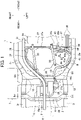
- FIG. 1 is a bottom view illustrating a rear part of a hybrid vehicle of the embodiment
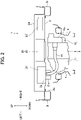
- FIG. 2 is a cross-sectional view illustrating a positional relationship between a drive unit and a power supply unit with respect to a floor when the rear part of the hybrid vehicle is likewise viewed from the rear.
- front-rear, left-right and up-down directions will be expressed with the driver in the vehicle as a main subject.
- a pair of left and right side members 3l and 3r are provided on an undersurface of a floor 2 that constitutes a vehicle body of a hybrid vehicle 1 and each side member 31 or 3r forms a closed cross section with the floor 2, and is extended in a front-rear direction.
- rear suspension cross members 4 are disposed on an underside of the floor 2 and both the left and right sides thereof are suspended and supported from the respective side members 31 and 3r. More specifically, fixed points 5fl, 5fr, 5rl and 5rr are provided as support mounts at front positions and rear positions of the left and right side members 31 and 3r, and front left and right, and rear left and right parts of the rear suspension cross member 4 are suspended and supported from the respective fixed points 5fl, 5fr, 5rl and 5rr. Both left and right sides of the rear suspension cross member 4 are extended forward from the fixed points 5fl and 5fr at the front positions and fastened to the left and right side members 3l and 3r by a pair of bolts 6l and 6r respectively.
- Left and right rear wheels 7 are supported to the left side and the right side of the rear suspension cross member 4 via double-wishbone based suspension (not shown). Since the configuration of the suspension is well known, detailed description will be omitted, but the suspension is constructed of an upper arm, a lower arm, a toe control link, a spring and an absorber or the like.
- a driving motor 9, an inverter 10 provided integrally with the driving motor 9 and a transaxle 11 that functions as a reduction gear, as a drive unit 8 are attached to the rear suspension cross member 4 under the floor 2 via a support mount (not shown) and the left and right rear wheels 7 are connected to the transaxle 11 via a pair of left and right drive shafts 12.
- the driving motor 9 is driven and controlled by the inverter 10.
- DC power from a driving battery 34 which will be described later, is converted to three-phase AC power by the inverter 10, supplied to the driving motor 9, and with rotation of the driving motor 9 reduced in the transaxle 11, the left and right rear wheels 7 are driven via the drive shafts 12.
- the rotation of the left and right rear wheels 7 is transmitted to the driving motor 9 via the drive shafts 12 and the transaxle 11, three-phase AC power generated by the driving motor 9 is converted to DC power by the inverter 10 and charged to the driving battery 34.
- a junction box 21, a charger 22 and a DC-AC inverter 23 are installed as a power supply unit 20 on the floor 2 in order from the left side.
- the junction box 21 is an apparatus that connects the driving battery 34 and various electric loads such as the driving motor 9
- the charger 22 is an apparatus that charges power from an external power supply at a charging station or the like to the driving battery 34
- the DC-AC inverter 23 is an apparatus that converts DC power of the driving battery 34 to AC power of 100 V for allowing home appliances to be used.
- the power supply unit 20 is covered with a cover 24 from above and a third row seat (not shown) is located directly above the power supply unit 20.
- the junction box 21 is connected to the charger 22 and the DC-AC inverter 23 via a power cable.
- a terminal block 21a is provided on an undersurface of the junction box 21, fitted into a through hole 2a formed in the floor 2 and protrudes downward.
- One end of a motor side power cable 25 is connected to a rear surface of the terminal block 21a and the other end is connected to a left side surface of a terminal block 10a of the inverter 10.
- a front part of the terminal block 21a of the junction box 21 is connected to the driving battery 34 via a battery-side power cable 26 (power line). Power is exchanged between the driving battery 34 and the charger 22 and between the DC-AC inverter 23 and the inverter 10 of the driving motor 9 by relaying the junction box 21.
- DC power from the driving battery 34 is supplied to the DC-AC inverter 23 via the junction box 21, converted to AC power of 100 V and used to operate home appliances.
- AC power supplied from an external power supply is converted to DC power by the charger 22 and charged to the driving battery 34 via the junction box 21.
- the above-described power drive control or regenerative control of the driving motor 9 is also performed via the junction box 21.
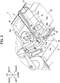
- FIG. 3 is a perspective view illustrating a power line routing state in the tank storage section when the rear bottom surface of the vehicle body of the hybrid vehicle 1 is viewed diagonally from the rear.
- front, middle and rear floor cross members 27 to 29 are provided between the left and right side members 3l and 3r under the floor 2, each cross member 27 to 29 is extended in a left-right direction while forming a closed cross section with the undersurface of the floor 2, both ends of which are connected to the left and right side members 31 and 3r.
- the respective fixed points 5fl, 5fr, 5rl and 5rr that suspend and support the above-described rear suspension cross member 4 are provided at positions of both ends of the middle and rear floor cross members 28 and 29.
- the front floor cross member 27 is disposed in front of the middle floor cross member 28, a tank storage section 30 opening downward is formed between the front and middle floor cross members 27 and 28 under the floor 2 and a battery storage section 31 opening downward is formed in front of the front floor cross member 27.
- a fuel tank 32 is disposed in the tank storage section 30, fixed with a pair of brackets 33 and contains fuel to be supplied to the engine (not shown) mounted on the front of the vehicle body.
- the driving battery 34 is disposed in the battery storage section 31 and the circumference of the driving battery 34 is fixed with bolts (not shown).
- FIG. 4 is a schematic view showing, on the same plane, an arrow view A of FIG. 1 when the side wall of the front floor cross member 27 is viewed from the rear and an arrow view B when the side wall of the left side member 31 is viewed from the right.
- a side wall 27a of the front floor cross member 27 and a side wall 31a of the left side member 31 are connected via a curved corner 36.
- a terminal block 34a is provided on the rear side of the driving battery 34, the terminal block 34a is located below the front floor cross member 27, a distal end of the terminal block 34a protrudes slightly rearward (fuel tank side) from the side wall 27a of the front floor cross member 27 facing into the tank storage section 30.
- the terminal built in the terminal block 34a is extended rearward from the driving battery 34 and has an L-shape bent upward.
- a connector opening upward (battery-side connector on the driving battery side) is formed at a protruding point at the distal end of the terminal block 34a, allowing a connector (not shown) provided at one end of the battery-side power cable 26 (power-line-side connector on the power line side) to be connected from above.
- the terminal block 34a is located below the front floor cross member 27 and the connector of the terminal block 34a opens upward.
- the connector of the battery-side power cable 26 connected to the connector of the terminal block 34a protrudes to the fuel tank 32 side, the battery-side power cable 26 is pulled out upward from this protruding point, directly guided by the side wall 27a of the front floor cross member 27, and further routed upward on the side wall 27a without significantly changing the extending direction.
- an upward pull-out state of the cable is intended for routing of the battery-side power cable 26 with slack.
- the connector structure is not limited to the aforementioned one as long as it can realize this pull-out state.
- a connector opening rearward is formed behind the terminal block 34a using an I-shaped terminal instead of the L-shaped terminal and a connector opening orthogonal to the cable longitudinal direction is provided at an end of the battery-side power cable 26.
- the connector is connected to the connector of the terminal block 34a from behind in a posture with the battery-side power cable 26 extended upward.
- the battery-side power cable 26 is pulled out upward from the terminal block 34a also in this case.
- the terminal block 34a is separated rightward from the corner 36 by a distance L shown in FIG. 4 , and the battery-side power cable 26 is routed with slack, as will be described hereinafter using an area on the side wall 27a of the front floor cross member 27 corresponding to this distance L.
- the point of the battery-side power cable 26 with slack is called an "extra length area 26a" and an area on the side wall 27a corresponding to the distance L whereby the extra length area 26a is routed is called an "extra length routing area 37.”
- the cooling pipe 38 is provided as a pair of pipe lines to circulate cooling water between the driving motor 9 and a heat sink (not shown) disposed on the front of the vehicle body and cooling action of the driving motor 9 is exerted by circulating the cooling water.
- each cooling pipe 38 is connected to the driving motor 9, extended forward, pulled into the tank storage section 30, extended forward so as to bypass the fuel tank 32 via the right side of the fuel tank 32 (the other of the left and right sides), and further extended leftward along the side wall 27a of the front floor cross member 27.
- each cooling pipe 38 is bent downward, and pulled out from the tank storage section 30.
- a pipe-shaped heat insulating material 39 made of synthetic resin material with thermal insulation and elasticity (first protector member) is fitted to each cooling pipe 38.
- each cooling pipe 38 is bent forward, extended forward beyond the undersurface of the front floor cross member 27 and connected to the heat sink (not shown).
- the battery-side power cable 26 is routed on the opposite side of the cooling pipe 38 in the tank storage section 30. That is, one end of the battery-side power cable 26 is connected to the front side of the terminal block 21a of the junction box 21, the battery-side power cable 26 is pulled into the tank storage section 30 and extended forward along the side wall 31a of the left side member 31 so as to bypass the fuel tank 32 via the left side of the fuel tank 32 (either one of the left and right sides).
- a pipe-shaped first covering material 40 made of synthetic resin material with high strength is fitted at a point where the battery-side power cable 26 is pulled into the tank storage section 30, and a bracket (not shown) formed integrally with the first covering material 40 is fixed to a bottom wall 30a or the like of the tank storage section 30 with bolts.
- a pipe-shaped second covering material 41 made of synthetic resin material with high strength (second protector member) is fitted at a point along the side wall 31a of the side member 31 of the battery-side power cable 26 and a pair of brackets 41a and 41b formed integrally with the second covering material 41 are fixed to a bottom wall 30a of the tank storage section 30 and a side wall 31a of the side member 31 with bolts 42, respectively.
- the battery-side power cable 26 With the fitting of the first and second covering materials 40 and 41, the battery-side power cable 26 is kept to a predetermined shape following the bottom wall 30a of the tank storage section 30 and the side wall 31a of the side member 31, and position displacement due to vibration or the like during vehicle running is prevented. In the event of a side collision from the left by another vehicle, the battery-side power cable 26 may be sandwiched between the side member 31 and the fuel tank 32 deformed to the right by impact, but the strong first and second covering materials 40 and 41 protect the battery-side power cable 26, preventing damage such as wire breakage.
- characteristics of the first and second covering materials 40 and 41 are not limited to the above-described characteristics, but as in the case of a third covering material 43, which will be described later, urethane material or the like may be used to provide high impact absorption to protect the battery-side power cable 26.
- the second covering material 41 extends forward along the side wall 31a of the side member 31, is bent rightward in the corner 36 reaching the side wall 27a of the front floor cross member 27. Since the curvature of the second covering material 41 is larger at the curved point than at the corner 36, a gap is formed between the curved point and the corner 36, and the heat insulating material 39 fitted to each cooling pipe 38 is located in the gap. As a result, in the corner 36, the battery-side power cable 26 and the cooling pipe 38 intersect each other (point of intersection), the second covering material 41 and the heat insulating material 39 fitted to the battery-side power cable 26 and the cooling pipe 38 respectively, are lightly in contact with or slightly separated from each other.
- the cooling pipe 38 is hot, its heat is blocked by the heat insulating material 39 and the second covering material 41, and so heat damage to the battery-side power cable 26 is prevented. Due to vibration during vehicle running, the second covering material 41 and the heat insulating material 39 may rub each other, but direct contact between the battery-side power cable 26 and the cooling pipe 38 is prevented, and this prevents trouble such as damage to the battery-side power cable 26 from occurring.
- the cooling pipe 38 is located on the front side (side wall 27a side of the front floor cross member 27) and the battery-side power cable 26 is located on the rear side (fuel tank 32 side).
- the behavior of the battery-side power cable 26 following position displacement of the terminal block 34a of the driving battery 34 is possible without being blocked by the cooling pipe 38 fixed to the side wall 27a of the front floor cross member 27.
- the battery-side power cable 26 is further extended rightward over the extra length routing area 37 along the side wall 27a of the front floor cross member 27 from an end of the second covering material 41 (end of the corner 36).
- the battery-side power cable 26 is routed with slack as the extra length area 26a and the third covering material 43 (third protector member) is fitted thereto, and a connector provided at an end of the extra length area 26a is connected to the connector of the terminal block 34a of the driving battery 34.
- a routing state of the extra length area 26a of the battery-side power cable 26 will be described by assuming the terminal block 34a side as a starting point based on FIG. 4 .
- the battery-side power cable 26 is pulled out upward from the terminal block 34a, extended upward along the side wall 27a of the front floor cross member 27 in the extra length routing area 37 of the side wall 27a, extended downward toward the side member 31, and further continued to the side wall 31a of the side member 31 after passing through the area of the corner 36.
- the battery-side power cable 26 is extended in a mountainous way, and the extra length area 26a is formed to provide slack.
- the extra length area 26a can be formed over the extra length routing area 37 of the side wall 27a without forcibly bending the battery-side power cable 26.
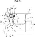
- FIG. 5 is a V-V line cross-sectional view of FIG. 4 illustrating a state in which the battery-side power cable 26 is fixed by a clip.
- the region of the battery-side power cable 26 corresponding to a vertex of the extra length area 26a is fixed to the side wall 27a of the front floor cross member 27 by a clip 45.
- the clip 45 is integrally molded with a synthetic resin material and constructed of a ring-shaped holding part 45a and a locking part 45b provided on one side of the holding part 45a.
- the third covering material 43 is externally fitted to the holding part 45a and the locking part 45b is elastically inserted/hooked into a clip hole 46 perforated in the side wall 27a of the front floor cross member 27.
- the extra length area 26a of the battery-side power cable 26 is fixed on the extra length routing area 37 of the side wall 27a via the clip 45 and the third covering material 43. Periodic shaking of the extra length area 26a due to vibration or the like during vehicle running may cause the battery-side power cable 26 to deteriorate, but fixing the clip 45 can prevent such a situation.
- the holding part 45a together with the locking part 45b is divided into upper and lower parts, for example, using a dividing line 47 shown in FIG. 5 as a boundary.
- a procedure for fixing the battery-side power cable 26 in this case is separating the locking part 45b first and inserting the battery-side power cable 26 to which the third covering material 43 is fitted in advance from one side into the holding part 45a after passing through the locking part 45b.
- the locking part 45b is connected, the third covering material 43 is held in the holding part 45a with no gaps, and the locking part 45b is inserted into the clip hole 46 of the side wall 27a in this state.
- the locking part 45b expands by its own elasticity and is hooked in the clip hole 46, and this completes the fixing work.
- Locking of the synthetic resin clip 45 by the locking part 45b is weaker than fastening by the metal bolts 42 that fix, for example, the second covering material 41. For this reason, although locking is maintained with the force normally received by the clip 45 such as vibration during vehicle running, locking is released when a larger predetermined load (more specifically, tension generated on the battery-side power cable 26 along with position displacement of the terminal block 34a, which will be described below) acts, and the clip 45 comes off the side wall 27a. As a result, in the event of a side collision by another vehicle, the behavior of the battery-side power cable 26 following position displacement of the terminal block 34a of the driving battery 34 is possible without being hindered by restraints of the clip 45.
- a larger predetermined load more specifically, tension generated on the battery-side power cable 26 along with position displacement of the terminal block 34a, which will be described below
- the third covering material 43 has characteristics different from those of the first and second covering materials 41. That is, the third covering material 43 is made of a urethane member or the like and is provided with high impact absorption and flexibility. Therefore, unlike the first and second covering materials 41 that protects the battery-side power cable 26 with high strength in the event of a side collision by another vehicle, the third covering material 43 absorbs impact and thereby protects the battery-side power cable 26 inside. For example, in the event of a side collision by another vehicle, a damaged peripheral member may contact the battery-side power cable 26, but the third covering material 43 protects the battery-side power cable 26 from damage.
- the third covering material 43 is highly flexible, in the event of a side collision by another vehicle, the behavior of the battery-side power cable 26 following position displacement of the terminal block 34a of the driving battery 34 is possible without being blocked by the third covering material 43.
- the battery-side power cable 26 will no longer be restrained by the clip 45 and the tension decreases rapidly.
- the terminal block 34a is further displaced to the right, but the semicircular extra length area 26a is stretched rightward, and the increase in the tension of the battery-side power cable 26 is suppressed, thus preventing damage such as wire breakage caused by tension.
- the brackets 41a and 41b that fix the battery-side power cable 26 to the side wall 31a of the side member 31 may not be damaged or the fuel tank 32 may escape from impact and may hardly be deformed.
- the brackets 41a and 41b keep the side member 31 fixed to the side wall 31a, and tension is generated in the battery-side power cable 26, whereas in the latter case, the behavior of the battery-side power cable 26 following the terminal block 34a is blocked by the fuel tank 32, which may generate tension and cause damage such as wire breakage in either case.
- the extra length area 26a is provided in the present embodiment, tension generated in the battery-side power cable 26 can be suppressed in any side-collision situation without falling into such a situation. As a result, the battery-side power cable 26 can be reliably protected in the event of a side collision by another vehicle.
- the aspects of the present invention are not limited to the above-described embodiment.
- the driving battery 34, the fuel tank 32 and the driving motor 9 are disposed in order from the front side of the vehicle body to drive the rear wheels 7, but the order may be reversed such that the driving battery 34, the fuel tank 32 and the driving motor 9 are disposed in order from the rear side of the vehicle body so as to drive the front wheels.
- the junction box 21 may be omitted and the driving battery 34 may be directly connected to the inverter 10 of the driving motor 9 via the battery-side power cable 26.
- the shape of the extra length area 26a is not limited to the semicircular shape, but can be arbitrarily changed.
- an upward convex semicircle and a downward convex semicircle may be combined to form a substantially S-shaped extra length area.
- the third covering material 43 is fitted to the extra length area 26a of the battery-side power cable 26 and fixed to the side wall 27a of the front floor cross member 27 with the clip 45, these requirements are not necessarily essential, but either one or both may be omitted.
Landscapes
- Engineering & Computer Science (AREA)
- Mechanical Engineering (AREA)
- Chemical & Material Sciences (AREA)
- Transportation (AREA)
- Combustion & Propulsion (AREA)
- Civil Engineering (AREA)
- Structural Engineering (AREA)
- Architecture (AREA)
- Arrangement Or Mounting Of Propulsion Units For Vehicles (AREA)
- Installation Of Indoor Wiring (AREA)
- Cooling, Air Intake And Gas Exhaust, And Fuel Tank Arrangements In Propulsion Units (AREA)
- Hybrid Electric Vehicles (AREA)
- Details Of Indoor Wiring (AREA)
Abstract
Description
- The present invention relates to a power line routing structure in a hybrid vehicle.
- As a hybrid vehicle, for example, Patent Document 1 discloses a vehicle equipped with a driving motor and an engine at the front of a vehicle body, and an IPU (electrical equipment for electric motors) made up of a driving battery, an inverter or the like in an IPU storage section formed under the floor at the rear of the vehicle body.
- The driving motor and the IPU are connected via three-phase power lines under the floor. However, since a tank storage section is formed in the center under the floor where a fuel tank for the engine is disposed, the power lines are routed so as to avoid the fuel tank. More specifically, the power line from the driving motor is extended backward in the center of a vehicle width direction, pulled into the tank storage section and fixed with a bracket or the like as appropriate while being extended along an inside wall of the tank storage section so as to bypass the fuel tank. Furthermore, the power line is pulled out from the tank storage section, extended backward in the center of the vehicle width direction again and connected to the IPU.
- Patent Document 1:
Japanese Patent Application Laid-Open No.2012-40893 - The technology described in Patent Document 1 is a routing structure of power lines that connect the inverter included in the IPU and the driving motor, but aside from this, there are also hybrid vehicles adopting a routing structure of power lines that connect a driving battery and an inverter integrated with a driving motor.
- In such hybrid vehicles, for example, a battery storage section is formed on a front side of cross members connecting left and right side members under the floor of the vehicle body to dispose the driving battery, a tank storage section is formed on a rear side of the cross members to dispose the fuel tank, and further a junction box is disposed on a rear side of the fuel tank to relay power from the driving battery to be supplied to the inverter. As a result, since the fuel tank is located between the driving battery and the junction box, a power line connecting a terminal block of the driving battery and a terminal block of the junction box needs to be routed so as to avoid the fuel tank as in the case of the technology in Patent Document 1.
- Thus, the power line from the terminal block provided on the rear side of the driving battery is pulled into the tank storage section, extended, for example, leftward along a side wall of the cross members in the tank storage section, further extended backward along the side wall of the side member on the left side, and fixed with a bracket or the like as appropriate. In this way, the power line is routed in the tank storage section so as to bypass the fuel tank, and moreover, the power line is pulled out of the tank storage section and connected to the terminal block of the junction box.
- However, with such a power line routing structure, there has been room for improvement in terms of power line protection in the event of a side collision by another vehicle.
- For example, when the power line is fixed to the left side member as described above, if another vehicle collides from the left at a front or back position that matches the driving battery, the terminal block is also displaced to the right together with the driving battery, which has been crushed by impact. By contrast, since the power lines are fixed to the side walls of the cross members and the side members and their position displacements are regulated, large tension is generated in the power line along with position displacement of the terminal block, causing damage such as wire breakage. Even if the bracket or the like is damaged and a restraint to the power line is released, the fuel tank that escapes from impact and is hardly displaced may interfere with the behavior of the power line following the terminal block, and so damage to the power line due to excessive tension is inevitable after all.
- An object of the present invention, which has been made to solve such problems, is to provide a power line routing structure in a hybrid vehicle capable of reliably protecting power lines in the event of a side collision by another vehicle with respect to the power line routing structure in which a driving battery and a driving motor are connected via power lines routed so as to bypass a fuel tank in a tank storage section.
- In order to achieve the above object, an aspect of the present invention is directed to a power line routing structure in a hybrid vehicle including a fuel tank disposed in a tank storage section formed between left and right side members on a lower side of a floor of a vehicle body, a driving battery disposed in a battery storage section aligned with the tank storage section in a front-rear direction across a cross member connecting between the left and right side members, a driving motor disposed on an opposite side of the battery storage section in the front-rear direction of the vehicle with respect to the tank storage section and a power line that supplies power from the driving battery to the driving motor, in which part of the tank storage section includes the left and right side members and the cross members, the power line is extended along a side wall of either one of the left and right side members from a side wall of the cross member so as to bypass the fuel tank via either one of the left and right sides of the fuel tank from a terminal block of the driving battery and an extra length area with slack being formed in an area of the power line along the side wall of the cross member (claim 1).
- According to the power line routing structure in a hybrid vehicle configured as described above, for example, when another vehicle collides from either one of the left and right sides (on the side on which the power line bypasses the fuel tank) at the position in a front-rear direction that corresponds to the driving battery, the driving battery is crushed in the left and right directions by the impact, and the terminal block is thereby displaced to the other of the left and right sides. With position displacement, the extra length area of the power line is stretched, and the increase in tension generated in the power line is suppressed.
- As another aspect, the power line is preferably extended in a mountainous way protruding upward along the side wall of the cross member to provide slack in the extra length area (claim 2).
- According to the power line routing structure in a hybrid vehicle configured as described above, the power line is extended in a mountainous way, and so an extra length area with slack being formed.
- As a further aspect, the terminal block of the driving battery is preferably disposed on a lower side of the cross member (claim 3).
- According to the power line routing structure in a hybrid vehicle configured as described above, since the terminal block is disposed under the cross member, the power line is directly guided from the terminal block to the side wall of the cross member.
- As a still further aspect, a battery-side connector on the driving battery side to which a power-line-side connector on the power line side is connected is preferably formed on the fuel tank side on the terminal block of the driving battery, and while the power-line-side connector is connected to the battery-side connector, the power-line-side connector preferably protrudes from the cross member to the fuel tank side and the power line is preferably extended upward from a position at which the power-line-side connector protrudes toward the fuel tank side (claim 4).
- According to the power line routing structure in a hybrid vehicle configured as described above, the power line is pulled out upward from the terminal block and routed upward on the side wall of the cross member without significantly changing the extension direction.
- As a still further aspect, the power line routing structure further includes a cooling pipe that circulates cooling water in the driving motor to cool the driving motor, in which the cooling pipe is preferably pulled into the tank storage section from the driving motor, extended along the side wall of the cross member so as to bypass the fuel tank via the other of the left and right sides of the fuel tank, and further extended passing through a point of intersection with the power line at a point of the side wall of the cross member, and at the point of intersection, the cooling pipe is preferably disposed on the cross member side and the power line is disposed on the fuel tank side (claim 5).
- According to the power line routing structure in a hybrid vehicle configured as described above, the behavior of the power line following position displacement of the terminal block of the driving battery is possible without being blocked by the cooling pipe in the event of a side collision of another vehicle.
- As a still further aspect, at the point of intersection, a first protector member is preferably fitted to the cooling pipe and a second protector member is preferably fitted to the power line (claim 6).
- According to the power line routing structure in a hybrid vehicle configured as described above, since heat of the cooling pipe is blocked by the first and second protector members, heat damage to the battery-side power cable is prevented.
- As a still further aspect, the second protector member is preferably extended from the point of intersection to an area along either one of the left and right side members (claim 7).
- According to the power line routing structure in a hybrid vehicle configured as described above, in the event of a side collision by another vehicle from either one of the left and right sides, the power line may be sandwiched between the side member deformed by impact and the fuel tank, but the power line is protected by the second protector member.
- As a still further aspect, in the area along either one of the left and right side members, the second protector member is preferably fixed to the floor panel of the vehicle body with a bolt, and in the extra length area, the power line is preferably fixed to the side wall of the cross member with a clip that comes off due to a predetermined load (claim 8).
- According to the power line routing structure in a hybrid vehicle configured as described above, periodic shaking of the extra length area due to vibration during vehicle running may cause deterioration of the battery-side power cable, but such a case is prevented by fixing with the clip.
- As a still further aspect, a third protector member with flexibility is preferably fitted to the power line in the extra length area (claim 9).
- According to the power line routing structure in a hybrid vehicle configured as described above, since the third protector member fitted to the power line is flexible, the behavior of the power line following position displacement of the terminal block of the driving battery is possible.
- According to the power line routing structure in a hybrid vehicle of the present invention, the power line routing structure in which the driving battery and the driving motor are connected via the power line routed so as to bypass the fuel tank in the tank storage section can reliably protect the power line in the event of a side collision by another vehicle.
-
-
FIG. 1 is a bottom view illustrating a rear part of a hybrid vehicle of an embodiment. -
FIG. 2 is a cross-sectional view illustrating a positional relationship between a drive unit and a power supply unit with respect to a floor when the rear part of the hybrid vehicle is viewed from the rear. -
FIG. 3 is a perspective view illustrating a power line routing state in a tank storage section when a rear bottom surface of the vehicle body of the hybrid vehicle is viewed diagonally from the rear. -
FIG. 4 is a schematic view showing, on the same plane, an arrow view A ofFIG. 1 when the side wall of the front floor cross member is viewed from the rear and an arrow view B when the side wall of the left side member is viewed from the right. -
FIG. 5 is a V-V line cross-sectional view ofFIG. 4 illustrating a state in which the battery-side power cable 26 is fixed by a clip. - Hereinafter, an embodiment of a power line routing structure in a hybrid vehicle that embodies the present invention will be described.
-
FIG. 1 is a bottom view illustrating a rear part of a hybrid vehicle of the embodiment andFIG. 2 is a cross-sectional view illustrating a positional relationship between a drive unit and a power supply unit with respect to a floor when the rear part of the hybrid vehicle is likewise viewed from the rear. In the following description, front-rear, left-right and up-down directions will be expressed with the driver in the vehicle as a main subject. - As shown in
FIGS. 1 and2 , a pair of left andright side members 3l and 3r are provided on an undersurface of afloor 2 that constitutes a vehicle body of a hybrid vehicle 1 and eachside member floor 2, and is extended in a front-rear direction. - As shown by two-dot dashed lines in
FIG. 1 , rearsuspension cross members 4 are disposed on an underside of thefloor 2 and both the left and right sides thereof are suspended and supported from therespective side members right side members suspension cross member 4 are suspended and supported from the respective fixed points 5fl, 5fr, 5rl and 5rr. Both left and right sides of the rearsuspension cross member 4 are extended forward from the fixed points 5fl and 5fr at the front positions and fastened to the left andright side members 3l and 3r by a pair ofbolts 6l and 6r respectively. - Left and right rear wheels 7 (only the right side is shown in
FIG. 1 ) are supported to the left side and the right side of the rearsuspension cross member 4 via double-wishbone based suspension (not shown). Since the configuration of the suspension is well known, detailed description will be omitted, but the suspension is constructed of an upper arm, a lower arm, a toe control link, a spring and an absorber or the like. Adriving motor 9, aninverter 10 provided integrally with thedriving motor 9 and atransaxle 11 that functions as a reduction gear, as adrive unit 8, are attached to the rearsuspension cross member 4 under thefloor 2 via a support mount (not shown) and the left and rightrear wheels 7 are connected to thetransaxle 11 via a pair of left andright drive shafts 12. - The
driving motor 9 is driven and controlled by theinverter 10. For example, during power drive control, DC power from adriving battery 34, which will be described later, is converted to three-phase AC power by theinverter 10, supplied to the drivingmotor 9, and with rotation of thedriving motor 9 reduced in thetransaxle 11, the left and rightrear wheels 7 are driven via thedrive shafts 12. On the other hand, during regenerative control, the rotation of the left and rightrear wheels 7 is transmitted to the drivingmotor 9 via thedrive shafts 12 and thetransaxle 11, three-phase AC power generated by thedriving motor 9 is converted to DC power by theinverter 10 and charged to thedriving battery 34. - As shown in
FIG. 2 , ajunction box 21, a charger 22 and a DC-AC inverter 23 are installed as a power supply unit 20 on thefloor 2 in order from the left side. As is generally known, thejunction box 21 is an apparatus that connects thedriving battery 34 and various electric loads such as the drivingmotor 9, the charger 22 is an apparatus that charges power from an external power supply at a charging station or the like to the drivingbattery 34, and the DC-AC inverter 23 is an apparatus that converts DC power of the drivingbattery 34 to AC power of 100 V for allowing home appliances to be used. Note that the power supply unit 20 is covered with acover 24 from above and a third row seat (not shown) is located directly above the power supply unit 20. - Although not shown, the
junction box 21 is connected to the charger 22 and the DC-AC inverter 23 via a power cable. As shown inFIGS. 1 and2 , aterminal block 21a is provided on an undersurface of thejunction box 21, fitted into a throughhole 2a formed in thefloor 2 and protrudes downward. One end of a motorside power cable 25 is connected to a rear surface of theterminal block 21a and the other end is connected to a left side surface of aterminal block 10a of theinverter 10. - Although details will be described later, a front part of the
terminal block 21a of thejunction box 21 is connected to the drivingbattery 34 via a battery-side power cable 26 (power line). Power is exchanged between the drivingbattery 34 and the charger 22 and between the DC-AC inverter 23 and theinverter 10 of the drivingmotor 9 by relaying thejunction box 21. For example, DC power from the drivingbattery 34 is supplied to the DC-AC inverter 23 via thejunction box 21, converted to AC power of 100 V and used to operate home appliances. At a charging station or the like, AC power supplied from an external power supply is converted to DC power by the charger 22 and charged to the drivingbattery 34 via thejunction box 21. The above-described power drive control or regenerative control of the drivingmotor 9 is also performed via thejunction box 21. -
FIG. 3 is a perspective view illustrating a power line routing state in the tank storage section when the rear bottom surface of the vehicle body of the hybrid vehicle 1 is viewed diagonally from the rear. - As shown in
FIGS. 1 and3 , front, middle and rearfloor cross members 27 to 29 are provided between the left andright side members 3l and 3r under thefloor 2, eachcross member 27 to 29 is extended in a left-right direction while forming a closed cross section with the undersurface of thefloor 2, both ends of which are connected to the left andright side members suspension cross member 4 are provided at positions of both ends of the middle and rearfloor cross members - The front
floor cross member 27 is disposed in front of the middlefloor cross member 28, atank storage section 30 opening downward is formed between the front and middlefloor cross members floor 2 and abattery storage section 31 opening downward is formed in front of the frontfloor cross member 27. As a result, thetank storage section 30 and thebattery storage section 31 are juxtaposed in the front-rear direction. Afuel tank 32 is disposed in thetank storage section 30, fixed with a pair ofbrackets 33 and contains fuel to be supplied to the engine (not shown) mounted on the front of the vehicle body. The drivingbattery 34 is disposed in thebattery storage section 31 and the circumference of the drivingbattery 34 is fixed with bolts (not shown). -
FIG. 4 is a schematic view showing, on the same plane, an arrow view A ofFIG. 1 when the side wall of the frontfloor cross member 27 is viewed from the rear and an arrow view B when the side wall of theleft side member 31 is viewed from the right. - As shown in
FIGS. 1 and4 , in thetank storage section 30, aside wall 27a of the frontfloor cross member 27 and a side wall 31a of theleft side member 31 are connected via acurved corner 36. Aterminal block 34a is provided on the rear side of the drivingbattery 34, theterminal block 34a is located below the frontfloor cross member 27, a distal end of theterminal block 34a protrudes slightly rearward (fuel tank side) from theside wall 27a of the frontfloor cross member 27 facing into thetank storage section 30. Although not shown, the terminal built in theterminal block 34a is extended rearward from the drivingbattery 34 and has an L-shape bent upward. Thus, a connector opening upward (battery-side connector on the driving battery side) is formed at a protruding point at the distal end of theterminal block 34a, allowing a connector (not shown) provided at one end of the battery-side power cable 26 (power-line-side connector on the power line side) to be connected from above. - Thus, the
terminal block 34a is located below the frontfloor cross member 27 and the connector of theterminal block 34a opens upward. For this reason, the connector of the battery-side power cable 26 connected to the connector of theterminal block 34a protrudes to thefuel tank 32 side, the battery-side power cable 26 is pulled out upward from this protruding point, directly guided by theside wall 27a of the frontfloor cross member 27, and further routed upward on theside wall 27a without significantly changing the extending direction. Although details will be described later, such an upward pull-out state of the cable is intended for routing of the battery-side power cable 26 with slack. - Note that the connector structure is not limited to the aforementioned one as long as it can realize this pull-out state. For example, a connector opening rearward is formed behind the
terminal block 34a using an I-shaped terminal instead of the L-shaped terminal and a connector opening orthogonal to the cable longitudinal direction is provided at an end of the battery-side power cable 26. The connector is connected to the connector of theterminal block 34a from behind in a posture with the battery-side power cable 26 extended upward. The battery-side power cable 26 is pulled out upward from theterminal block 34a also in this case. - Similarly, for routing the battery-
side power cable 26 with slack, theterminal block 34a is separated rightward from thecorner 36 by a distance L shown inFIG. 4 , and the battery-side power cable 26 is routed with slack, as will be described hereinafter using an area on theside wall 27a of the frontfloor cross member 27 corresponding to this distance L. In the following description, the point of the battery-side power cable 26 with slack is called an "extra length area 26a" and an area on theside wall 27a corresponding to the distance L whereby theextra length area 26a is routed is called an "extralength routing area 37." - Since the routing of the battery-
side power cable 26 is associated with a coolingpipe 38 routed likewise in thetank storage section 30, a routing state of the coolingpipe 38 will be described first. The coolingpipe 38 is provided as a pair of pipe lines to circulate cooling water between the drivingmotor 9 and a heat sink (not shown) disposed on the front of the vehicle body and cooling action of the drivingmotor 9 is exerted by circulating the cooling water. - As shown in
FIGS. 1 ,3 and4 , one end of each coolingpipe 38 is connected to the drivingmotor 9, extended forward, pulled into thetank storage section 30, extended forward so as to bypass thefuel tank 32 via the right side of the fuel tank 32 (the other of the left and right sides), and further extended leftward along theside wall 27a of the frontfloor cross member 27. In thecorner 36 between theside wall 27a of the frontfloor cross member 27 and the side wall 31a of theleft side member 31, each coolingpipe 38 is bent downward, and pulled out from thetank storage section 30. A pipe-shapedheat insulating material 39 made of synthetic resin material with thermal insulation and elasticity (first protector member) is fitted to each coolingpipe 38. Furthermore, each coolingpipe 38 is bent forward, extended forward beyond the undersurface of the frontfloor cross member 27 and connected to the heat sink (not shown). - In order to avoid heat damage from the cooling
pipe 38 in which hot cooling water circulates, the battery-side power cable 26 is routed on the opposite side of the coolingpipe 38 in thetank storage section 30. That is, one end of the battery-side power cable 26 is connected to the front side of theterminal block 21a of thejunction box 21, the battery-side power cable 26 is pulled into thetank storage section 30 and extended forward along the side wall 31a of theleft side member 31 so as to bypass thefuel tank 32 via the left side of the fuel tank 32 (either one of the left and right sides). - A pipe-shaped first covering
material 40 made of synthetic resin material with high strength is fitted at a point where the battery-side power cable 26 is pulled into thetank storage section 30, and a bracket (not shown) formed integrally with thefirst covering material 40 is fixed to abottom wall 30a or the like of thetank storage section 30 with bolts. Similarly, a pipe-shaped second coveringmaterial 41 made of synthetic resin material with high strength (second protector member) is fitted at a point along the side wall 31a of theside member 31 of the battery-side power cable 26 and a pair ofbrackets second covering material 41 are fixed to abottom wall 30a of thetank storage section 30 and a side wall 31a of theside member 31 withbolts 42, respectively. - With the fitting of the first and
second covering materials side power cable 26 is kept to a predetermined shape following thebottom wall 30a of thetank storage section 30 and the side wall 31a of theside member 31, and position displacement due to vibration or the like during vehicle running is prevented. In the event of a side collision from the left by another vehicle, the battery-side power cable 26 may be sandwiched between theside member 31 and thefuel tank 32 deformed to the right by impact, but the strong first andsecond covering materials side power cable 26, preventing damage such as wire breakage. - Note that characteristics of the first and
second covering materials third covering material 43, which will be described later, urethane material or the like may be used to provide high impact absorption to protect the battery-side power cable 26. - The
second covering material 41 extends forward along the side wall 31a of theside member 31, is bent rightward in thecorner 36 reaching theside wall 27a of the frontfloor cross member 27. Since the curvature of thesecond covering material 41 is larger at the curved point than at thecorner 36, a gap is formed between the curved point and thecorner 36, and theheat insulating material 39 fitted to each coolingpipe 38 is located in the gap. As a result, in thecorner 36, the battery-side power cable 26 and the coolingpipe 38 intersect each other (point of intersection), thesecond covering material 41 and theheat insulating material 39 fitted to the battery-side power cable 26 and the coolingpipe 38 respectively, are lightly in contact with or slightly separated from each other. - Although the cooling
pipe 38 is hot, its heat is blocked by theheat insulating material 39 and thesecond covering material 41, and so heat damage to the battery-side power cable 26 is prevented. Due to vibration during vehicle running, thesecond covering material 41 and theheat insulating material 39 may rub each other, but direct contact between the battery-side power cable 26 and the coolingpipe 38 is prevented, and this prevents trouble such as damage to the battery-side power cable 26 from occurring. - In the state of intersection between the above-described battery-
side power cable 26 andcooling pipe 38, the coolingpipe 38 is located on the front side (side wall 27a side of the front floor cross member 27) and the battery-side power cable 26 is located on the rear side (fuel tank 32 side). Thus, in the event of a side collision by another vehicle, which will be described later, the behavior of the battery-side power cable 26 following position displacement of theterminal block 34a of the drivingbattery 34 is possible without being blocked by the coolingpipe 38 fixed to theside wall 27a of the frontfloor cross member 27. - As shown in
FIG. 4 , the battery-side power cable 26 is further extended rightward over the extralength routing area 37 along theside wall 27a of the frontfloor cross member 27 from an end of the second covering material 41 (end of the corner 36). In this extralength routing area 37, the battery-side power cable 26 is routed with slack as theextra length area 26a and the third covering material 43 (third protector member) is fitted thereto, and a connector provided at an end of theextra length area 26a is connected to the connector of theterminal block 34a of the drivingbattery 34. - A routing state of the
extra length area 26a of the battery-side power cable 26 will be described by assuming theterminal block 34a side as a starting point based onFIG. 4 . First, the battery-side power cable 26 is pulled out upward from theterminal block 34a, extended upward along theside wall 27a of the frontfloor cross member 27 in the extralength routing area 37 of theside wall 27a, extended downward toward theside member 31, and further continued to the side wall 31a of theside member 31 after passing through the area of thecorner 36. In this way, the battery-side power cable 26 is extended in a mountainous way, and theextra length area 26a is formed to provide slack. - As described above, since the
terminal block 34a is located below the frontfloor cross member 27 and the connector of theterminal block 34a is open upward, theextra length area 26a can be formed over the extralength routing area 37 of theside wall 27a without forcibly bending the battery-side power cable 26. -
FIG. 5 is a V-V line cross-sectional view ofFIG. 4 illustrating a state in which the battery-side power cable 26 is fixed by a clip. - As shown in
FIGS. 4 and5 , the region of the battery-side power cable 26 corresponding to a vertex of theextra length area 26a is fixed to theside wall 27a of the frontfloor cross member 27 by aclip 45. - The
clip 45 is integrally molded with a synthetic resin material and constructed of a ring-shaped holdingpart 45a and a lockingpart 45b provided on one side of the holdingpart 45a. Thethird covering material 43 is externally fitted to the holdingpart 45a and the lockingpart 45b is elastically inserted/hooked into aclip hole 46 perforated in theside wall 27a of the frontfloor cross member 27. Thus, theextra length area 26a of the battery-side power cable 26 is fixed on the extralength routing area 37 of theside wall 27a via theclip 45 and thethird covering material 43. Periodic shaking of theextra length area 26a due to vibration or the like during vehicle running may cause the battery-side power cable 26 to deteriorate, but fixing theclip 45 can prevent such a situation. - In order to externally fit the holding
part 45a of theclip 45 to thethird covering material 43, which has been fitted to the battery-side power cable 26, the holdingpart 45a together with the lockingpart 45b is divided into upper and lower parts, for example, using adividing line 47 shown inFIG. 5 as a boundary. A procedure for fixing the battery-side power cable 26 in this case is separating the lockingpart 45b first and inserting the battery-side power cable 26 to which thethird covering material 43 is fitted in advance from one side into the holdingpart 45a after passing through the lockingpart 45b. Next, when the lockingpart 45b is connected, thethird covering material 43 is held in the holdingpart 45a with no gaps, and the lockingpart 45b is inserted into theclip hole 46 of theside wall 27a in this state. The lockingpart 45b expands by its own elasticity and is hooked in theclip hole 46, and this completes the fixing work. - Locking of the
synthetic resin clip 45 by the lockingpart 45b is weaker than fastening by themetal bolts 42 that fix, for example, thesecond covering material 41. For this reason, although locking is maintained with the force normally received by theclip 45 such as vibration during vehicle running, locking is released when a larger predetermined load (more specifically, tension generated on the battery-side power cable 26 along with position displacement of theterminal block 34a, which will be described below) acts, and theclip 45 comes off theside wall 27a. As a result, in the event of a side collision by another vehicle, the behavior of the battery-side power cable 26 following position displacement of theterminal block 34a of the drivingbattery 34 is possible without being hindered by restraints of theclip 45. - On the other hand, the
third covering material 43 has characteristics different from those of the first andsecond covering materials 41. That is, thethird covering material 43 is made of a urethane member or the like and is provided with high impact absorption and flexibility. Therefore, unlike the first andsecond covering materials 41 that protects the battery-side power cable 26 with high strength in the event of a side collision by another vehicle, thethird covering material 43 absorbs impact and thereby protects the battery-side power cable 26 inside. For example, in the event of a side collision by another vehicle, a damaged peripheral member may contact the battery-side power cable 26, but thethird covering material 43 protects the battery-side power cable 26 from damage. - At the same time, since the
third covering material 43 is highly flexible, in the event of a side collision by another vehicle, the behavior of the battery-side power cable 26 following position displacement of theterminal block 34a of the drivingbattery 34 is possible without being blocked by thethird covering material 43. - Next, protective action in the event of a side collision by another vehicle, provided by the routing structure for the battery-
side power cable 26 configured as described above will be described. - For example, when another vehicle collides from the left at a position in a front-rear direction that corresponds to the driving
battery 34, the drivingbattery 34 is crushed in the left-right direction by impact, and theterminal block 34a is thereby displaced to the right as shown by two-dot dashed lines inFIG. 4 . With position displacement, tension is generated in the battery-side power cable 26 and this tension acts as a downward force on theclip 45 that fixes the battery-side power cable 26. With rightward position displacement of theterminal block 34a, the tension of the battery-side power cable 26 increases, but locking by the lockingpart 45b of theclip 45 is released before damage such as wire breakage occurs in the battery-side power cable 26. - As a result, the battery-
side power cable 26 will no longer be restrained by theclip 45 and the tension decreases rapidly. Theterminal block 34a is further displaced to the right, but the semicircularextra length area 26a is stretched rightward, and the increase in the tension of the battery-side power cable 26 is suppressed, thus preventing damage such as wire breakage caused by tension. - Such tension restraining action is exerted by the
extra length area 26a, which is action that can be surely obtained regardless of restrained states of other areas of the battery-side power cable 26. - That is, depending on a situation of side collision, the
brackets side power cable 26 to the side wall 31a of theside member 31 may not be damaged or thefuel tank 32 may escape from impact and may hardly be deformed. As the prior art described in "Problems to be Solved by the Invention," if it is assumed that noextra length area 26a is provided for the battery-side power cable 26 of the present embodiment, in the former case, thebrackets side member 31 fixed to the side wall 31a, and tension is generated in the battery-side power cable 26, whereas in the latter case, the behavior of the battery-side power cable 26 following theterminal block 34a is blocked by thefuel tank 32, which may generate tension and cause damage such as wire breakage in either case. - Since the
extra length area 26a is provided in the present embodiment, tension generated in the battery-side power cable 26 can be suppressed in any side-collision situation without falling into such a situation. As a result, the battery-side power cable 26 can be reliably protected in the event of a side collision by another vehicle. - Although this completes the description of the embodiment, the aspects of the present invention are not limited to the above-described embodiment. According to the above-described embodiment, for example, the driving
battery 34, thefuel tank 32 and the drivingmotor 9 are disposed in order from the front side of the vehicle body to drive therear wheels 7, but the order may be reversed such that the drivingbattery 34, thefuel tank 32 and the drivingmotor 9 are disposed in order from the rear side of the vehicle body so as to drive the front wheels. - According to the above-described embodiment, although the driving
battery 34 and thejunction box 21 are connected via the battery-side power cable 26, thejunction box 21 may be omitted and the drivingbattery 34 may be directly connected to theinverter 10 of the drivingmotor 9 via the battery-side power cable 26. - According to the above-described embodiment, although the semicircular
extra length area 26a is formed, the shape of theextra length area 26a is not limited to the semicircular shape, but can be arbitrarily changed. For example, an upward convex semicircle and a downward convex semicircle may be combined to form a substantially S-shaped extra length area. - According to the above-described embodiment, although the
third covering material 43 is fitted to theextra length area 26a of the battery-side power cable 26 and fixed to theside wall 27a of the frontfloor cross member 27 with theclip 45, these requirements are not necessarily essential, but either one or both may be omitted. -
- 1
- hybrid vehicle
- 2
- floor
- 31, 3r
- side member
- 31a
- side wall
- 9
- driving motor
- 26
- battery-side power cable (power line)
- 26a
- extra length area
- 27
- front floor cross member (cross member)
- 27a
- side wall
- 30
- tank storage section
- 31
- battery storage section
- 32
- fuel tank
- 34
- driving battery
- 34a
- terminal block
- 38
- cooling pipe
- 39
- heat insulating material (first protector member)
- 41
- second covering material (second protector member)
- 42
- bolt
- 43
- third covering material (third protector member)
- 45
- clip
Claims (9)
- A power line routing structure in a hybrid vehicle comprising:a fuel tank disposed in a tank storage section formed between left and right side members on a lower side of a floor of a vehicle body;a driving battery disposed in a battery storage section aligned with the tank storage section in a front-rear direction across a cross member connecting between the left and right side members;a driving motor disposed on an opposite side of the battery storage section in the front-rear direction of the vehicle with respect to the tank storage section; anda power line that supplies power from the driving battery to the driving motor, whereinpart of the tank storage section includes the left and right side members and the cross members, andthe power line is extended along a side wall of either one of the left and right side members from a side wall of the cross member so as to bypass the fuel tank via either one of the left and right sides of the fuel tank from a terminal block of the driving battery and an extra length area with slack being formed in an area of the power line along the side wall of the cross member.
- The power line routing structure in a hybrid vehicle, wherein the power line is extended in a mountainous way protruding upward along the side wall of the cross member to provide slack in the extra length area.
- The power line routing structure in a hybrid vehicle according to claim 1 or 2, wherein the terminal block of the driving battery is disposed on a lower side of the cross member.
- The power line routing structure in a hybrid vehicle according to any one of claims 1 to 3, whereina battery-side connector on the driving battery side to which a power-line-side connector on the power line side is connected is formed on the fuel tank side on the terminal block of the driving battery, andwhile the power-line-side connector is connected to the battery-side connector, the power-line-side connector protrudes from the cross member toward the fuel tank side and the power line is extended upward from a position at which the power-line-side connector protrudes toward the fuel tank side.
- The power line routing structure in a hybrid vehicle according to any one of claims 1 to 4, further comprising a cooling pipe that cools the driving motor by circulating cooling water in the driving motor, whereinthe cooling pipe is pulled into the tank storage section from the driving motor, extended along the side wall of the cross member so as to bypass the fuel tank via the other of the left and right sides of the fuel tank, and further extended passing through an intersection with the power line at a point of the side wall of the cross member, andat the point of intersection, the cooling pipe is disposed on the cross member side and the power line is disposed on the fuel tank side.
- The power line routing structure in a hybrid vehicle according to claim 5, wherein at the point of intersection, a first protector member is fitted to the cooling pipe and a second protector member is fitted to the power line.
- The power line routing structure in a hybrid vehicle according to claim 6, wherein the second protector member is extended from the point of intersection to an area along either one of the left and right side members.
- The power line routing structure in a hybrid vehicle according to claim 7, whereinin the area along either one of the left and right side members, the second protector member is fixed to the floor panel of the vehicle body with a bolt, andin the extra length area, the power line is fixed to the side wall of the cross member with a clip that comes off due to a predetermined load.
- The power line routing structure in a hybrid vehicle according to any one of claims 1 to 8, wherein a third protector member with flexibility is fitted to the power line in the extra length area.
Applications Claiming Priority (2)
| Application Number | Priority Date | Filing Date | Title |
|---|---|---|---|
| JP2020026519 | 2020-02-19 | ||
| PCT/JP2020/041652 WO2021166337A1 (en) | 2020-02-19 | 2020-11-09 | Wiring structure of power line in hybrid vehicle |
Publications (3)
| Publication Number | Publication Date |
|---|---|
| EP4108493A1 true EP4108493A1 (en) | 2022-12-28 |
| EP4108493A4 EP4108493A4 (en) | 2023-10-04 |
| EP4108493B1 EP4108493B1 (en) | 2025-01-01 |
Family
ID=77390562
Family Applications (1)
| Application Number | Title | Priority Date | Filing Date |
|---|---|---|---|
| EP20920257.1A Active EP4108493B1 (en) | 2020-02-19 | 2020-11-09 | Hybrid vehicle with a power line |
Country Status (5)
| Country | Link |
|---|---|
| US (1) | US12233696B2 (en) |
| EP (1) | EP4108493B1 (en) |
| JP (1) | JP7368795B2 (en) |
| CN (1) | CN115135536A (en) |
| WO (1) | WO2021166337A1 (en) |
Families Citing this family (11)
| Publication number | Priority date | Publication date | Assignee | Title |
|---|---|---|---|---|
| WO2021145057A1 (en) * | 2020-01-17 | 2021-07-22 | 三菱自動車工業株式会社 | Arrangement structure of drive unit and power supply unit in electric vehicle |
| WO2021166337A1 (en) | 2020-02-19 | 2021-08-26 | 三菱自動車工業株式会社 | Wiring structure of power line in hybrid vehicle |
| CN115892231B (en) * | 2021-09-30 | 2025-11-04 | 马自达汽车株式会社 | Vehicle body structure |
| JP7753816B2 (en) * | 2021-09-30 | 2025-10-15 | マツダ株式会社 | Body structure |
| JP7664146B2 (en) * | 2021-10-18 | 2025-04-17 | 日産自動車株式会社 | Vehicle protection structure |
| JP7715125B2 (en) * | 2022-11-04 | 2025-07-30 | トヨタ自動車株式会社 | vehicle |
| EP4729365A1 (en) * | 2023-06-14 | 2026-04-22 | Nissan Motor Co., Ltd. | Harness attachment structure |
| FR3151553B1 (en) * | 2023-07-25 | 2025-07-18 | Renault Sas | Arrangement for motor vehicle. |
| WO2025083866A1 (en) * | 2023-10-20 | 2025-04-24 | 日産自動車株式会社 | Power unit protection structure for vehicle |
| FR3162681A1 (en) * | 2024-05-28 | 2025-12-05 | Renault Sas | Fireproof protection device for a hybrid motor vehicle |
| FR3166112A1 (en) * | 2024-09-10 | 2026-03-13 | Renault Sas | Arrangement for motor vehicle. |
Family Cites Families (18)
| Publication number | Priority date | Publication date | Assignee | Title |
|---|---|---|---|---|
| JP3571677B2 (en) * | 2001-09-03 | 2004-09-29 | 本田技研工業株式会社 | Wiring structure of motor for hybrid vehicle |
| JP3815456B2 (en) * | 2003-04-09 | 2006-08-30 | トヨタ自動車株式会社 | Arrangement structure of high-voltage wires in hybrid vehicles |
| JP4825583B2 (en) | 2005-06-28 | 2011-11-30 | 本田技研工業株式会社 | Body structure |
| JP4355366B2 (en) * | 2005-11-10 | 2009-10-28 | 日産自動車株式会社 | High-voltage harness wiring structure for vehicles |
| FR2959454B1 (en) * | 2010-04-30 | 2012-06-01 | Peugeot Citroen Automobiles Sa | HYBRID VEHICLE HAVING A HIGH VOLTAGE BATTERY IMPLANTED UNDER THE FLOOR OF THE VEHICLE, BLOCK FORMED BY A RESERVOIR AND A HIGH VOLTAGE BATTERY, AND REPLACEMENT METHOD THEREFOR |
| JP5658942B2 (en) * | 2010-08-12 | 2015-01-28 | 本田技研工業株式会社 | Hybrid vehicle |
| JP5660111B2 (en) * | 2012-11-30 | 2015-01-28 | トヨタ自動車株式会社 | Cable routing structure in the motor room of an electric vehicle |
| JP6314757B2 (en) * | 2014-09-04 | 2018-04-25 | 日産自動車株式会社 | Rear structure of electric vehicle body |
| JP6271615B2 (en) * | 2016-02-12 | 2018-01-31 | 本田技研工業株式会社 | Cable structure and vehicle |
| JP6706507B2 (en) * | 2016-02-12 | 2020-06-10 | 本田技研工業株式会社 | vehicle |
| JP6286459B2 (en) * | 2016-02-12 | 2018-02-28 | 本田技研工業株式会社 | vehicle |
| JP6357512B2 (en) * | 2016-09-13 | 2018-07-11 | 本田技研工業株式会社 | Harness holder, power equipment unit and vehicle |
| JP6645400B2 (en) * | 2016-11-02 | 2020-02-14 | トヨタ自動車株式会社 | Electric car |
| JP6922763B2 (en) * | 2018-01-30 | 2021-08-18 | トヨタ自動車株式会社 | Vehicle undercarriage |
| JP2019151174A (en) * | 2018-03-01 | 2019-09-12 | 三菱自動車工業株式会社 | Arrangement structure of power source unit in electric vehicle |
| JP2020026159A (en) * | 2018-08-09 | 2020-02-20 | トヨタ自動車株式会社 | Vehicle lower part structure |
| WO2021145057A1 (en) * | 2020-01-17 | 2021-07-22 | 三菱自動車工業株式会社 | Arrangement structure of drive unit and power supply unit in electric vehicle |
| WO2021166337A1 (en) | 2020-02-19 | 2021-08-26 | 三菱自動車工業株式会社 | Wiring structure of power line in hybrid vehicle |
-
2020
- 2020-11-09 WO PCT/JP2020/041652 patent/WO2021166337A1/en not_active Ceased
- 2020-11-09 US US17/761,405 patent/US12233696B2/en active Active
- 2020-11-09 EP EP20920257.1A patent/EP4108493B1/en active Active
- 2020-11-09 JP JP2022501628A patent/JP7368795B2/en active Active
- 2020-11-09 CN CN202080065889.5A patent/CN115135536A/en active Pending
Also Published As
| Publication number | Publication date |
|---|---|
| EP4108493B1 (en) | 2025-01-01 |
| US20220371420A1 (en) | 2022-11-24 |
| CN115135536A (en) | 2022-09-30 |
| WO2021166337A1 (en) | 2021-08-26 |
| JPWO2021166337A1 (en) | 2021-08-26 |
| JP7368795B2 (en) | 2023-10-25 |
| EP4108493A4 (en) | 2023-10-04 |
| US12233696B2 (en) | 2025-02-25 |
Similar Documents
| Publication | Publication Date | Title |
|---|---|---|
| EP4108493B1 (en) | Hybrid vehicle with a power line | |
| US9827923B2 (en) | Harness routing structure for electric vehicle | |
| JP7438481B2 (en) | Vehicle front structure | |
| CN104284791B (en) | Electronlmobil | |
| CN106347090B (en) | vehicle | |
| EP4092880B1 (en) | ELECTRIC VEHICLE WITH AN ARRANGEMENT CONSISTING OF A DRIVE UNIT AND A POWER SUPPLY UNIT | |
| JP5446537B2 (en) | Electric vehicle mounting structure | |
| JP7151231B2 (en) | Vehicle power supply fixing structure | |
| JP7339608B2 (en) | Layout structure of power supply units in electric vehicles | |
| JP4924671B2 (en) | Electric vehicle mounting structure | |
| US20120031690A1 (en) | Vehicle component mounting structure | |
| CN102555754B (en) | The Wiring harness arrangement structure of vehicle | |
| JPWO2017110138A1 (en) | High voltage control equipment unit mounting structure | |
| JP5928289B2 (en) | High voltage harness protection structure for vehicles | |
| JP7087834B2 (en) | In-vehicle structure of electrical equipment | |
| JP2019166916A (en) | Front part unit mounting structure of electric vehicle | |
| US20250269745A1 (en) | Power unit room installing structure | |
| JP6753156B2 (en) | Battery pack protection structure | |
| JP7324420B2 (en) | Connector protective structure | |
| JP2019166917A (en) | Front part unit mounting structure of electric vehicle | |
| EP4049899B1 (en) | Electrical equipment | |
| JP2023136720A (en) | Driving device of electric vehicle | |
| JP6996597B2 (en) | Battery pack protection structure | |
| US20250282208A1 (en) | Power unit mounting structure | |
| JP7234824B2 (en) | Installation structure of the motor drive device |
Legal Events
| Date | Code | Title | Description |
|---|---|---|---|
| STAA | Information on the status of an ep patent application or granted ep patent |
Free format text: STATUS: THE INTERNATIONAL PUBLICATION HAS BEEN MADE |
|
| PUAI | Public reference made under article 153(3) epc to a published international application that has entered the european phase |
Free format text: ORIGINAL CODE: 0009012 |
|
| STAA | Information on the status of an ep patent application or granted ep patent |
Free format text: STATUS: REQUEST FOR EXAMINATION WAS MADE |
|
| 17P | Request for examination filed |
Effective date: 20220331 |
|
| AK | Designated contracting states |
Kind code of ref document: A1 Designated state(s): AL AT BE BG CH CY CZ DE DK EE ES FI FR GB GR HR HU IE IS IT LI LT LU LV MC MK MT NL NO PL PT RO RS SE SI SK SM TR |
|
| DAV | Request for validation of the european patent (deleted) | ||
| DAX | Request for extension of the european patent (deleted) | ||
| REG | Reference to a national code |
Ref country code: DE Ref legal event code: R079 Free format text: PREVIOUS MAIN CLASS: B60K0011040000 Ipc: B60K0001040000 Ref document number: 602020044333 Country of ref document: DE |
|
| A4 | Supplementary search report drawn up and despatched |
Effective date: 20230904 |
|
| RIC1 | Information provided on ipc code assigned before grant |
Ipc: H02G 3/38 20060101ALN20230829BHEP Ipc: H02G 3/30 20060101ALI20230829BHEP Ipc: H02G 3/04 20060101ALI20230829BHEP Ipc: B60K 15/03 20060101ALI20230829BHEP Ipc: B60K 11/02 20060101ALI20230829BHEP Ipc: B60K 1/04 20190101AFI20230829BHEP |
|
| RIC1 | Information provided on ipc code assigned before grant |
Ipc: H02G 3/38 20060101ALN20240710BHEP Ipc: H02G 3/30 20060101ALI20240710BHEP Ipc: H02G 3/04 20060101ALI20240710BHEP Ipc: B60K 15/03 20060101ALI20240710BHEP Ipc: B60K 11/02 20060101ALI20240710BHEP Ipc: B60K 1/04 20190101AFI20240710BHEP |
|
| RIC1 | Information provided on ipc code assigned before grant |
Ipc: H02G 3/38 20060101ALN20240715BHEP Ipc: H02G 3/30 20060101ALI20240715BHEP Ipc: H02G 3/04 20060101ALI20240715BHEP Ipc: B60K 15/03 20060101ALI20240715BHEP Ipc: B60K 11/02 20060101ALI20240715BHEP Ipc: B60K 1/04 20190101AFI20240715BHEP |
|
| GRAP | Despatch of communication of intention to grant a patent |
Free format text: ORIGINAL CODE: EPIDOSNIGR1 |
|
| STAA | Information on the status of an ep patent application or granted ep patent |
Free format text: STATUS: GRANT OF PATENT IS INTENDED |
|
| RIC1 | Information provided on ipc code assigned before grant |
Ipc: H02G 3/38 20060101ALN20240808BHEP Ipc: H02G 3/30 20060101ALI20240808BHEP Ipc: H02G 3/04 20060101ALI20240808BHEP Ipc: B60K 15/03 20060101ALI20240808BHEP Ipc: B60K 11/02 20060101ALI20240808BHEP Ipc: B60K 1/04 20190101AFI20240808BHEP |
|
| INTG | Intention to grant announced |
Effective date: 20240827 |
|
| GRAS | Grant fee paid |
Free format text: ORIGINAL CODE: EPIDOSNIGR3 |
|
| GRAA | (expected) grant |
Free format text: ORIGINAL CODE: 0009210 |
|
| STAA | Information on the status of an ep patent application or granted ep patent |
Free format text: STATUS: THE PATENT HAS BEEN GRANTED |
|
| AK | Designated contracting states |
Kind code of ref document: B1 Designated state(s): AL AT BE BG CH CY CZ DE DK EE ES FI FR GB GR HR HU IE IS IT LI LT LU LV MC MK MT NL NO PL PT RO RS SE SI SK SM TR |
|
| REG | Reference to a national code |
Ref country code: GB Ref legal event code: FG4D |
|
| REG | Reference to a national code |
Ref country code: DE Ref legal event code: R096 Ref document number: 602020044333 Country of ref document: DE |
|
| REG | Reference to a national code |
Ref country code: CH Ref legal event code: EP |
|
| REG | Reference to a national code |
Ref country code: IE Ref legal event code: FG4D |
|
| REG | Reference to a national code |
Ref country code: LT Ref legal event code: MG9D |
|
| REG | Reference to a national code |
Ref country code: NL Ref legal event code: MP Effective date: 20250101 |
|
| REG | Reference to a national code |
Ref country code: AT Ref legal event code: MK05 Ref document number: 1755902 Country of ref document: AT Kind code of ref document: T Effective date: 20250101 |
|
| PG25 | Lapsed in a contracting state [announced via postgrant information from national office to epo] |
Ref country code: NL Free format text: LAPSE BECAUSE OF FAILURE TO SUBMIT A TRANSLATION OF THE DESCRIPTION OR TO PAY THE FEE WITHIN THE PRESCRIBED TIME-LIMIT Effective date: 20250101 |
|
| PG25 | Lapsed in a contracting state [announced via postgrant information from national office to epo] |
Ref country code: FI Free format text: LAPSE BECAUSE OF FAILURE TO SUBMIT A TRANSLATION OF THE DESCRIPTION OR TO PAY THE FEE WITHIN THE PRESCRIBED TIME-LIMIT Effective date: 20250101 |
|
| PG25 | Lapsed in a contracting state [announced via postgrant information from national office to epo] |
Ref country code: PL Free format text: LAPSE BECAUSE OF FAILURE TO SUBMIT A TRANSLATION OF THE DESCRIPTION OR TO PAY THE FEE WITHIN THE PRESCRIBED TIME-LIMIT Effective date: 20250101 |
|
| PG25 | Lapsed in a contracting state [announced via postgrant information from national office to epo] |
Ref country code: ES Free format text: LAPSE BECAUSE OF FAILURE TO SUBMIT A TRANSLATION OF THE DESCRIPTION OR TO PAY THE FEE WITHIN THE PRESCRIBED TIME-LIMIT Effective date: 20250101 |
|
| PG25 | Lapsed in a contracting state [announced via postgrant information from national office to epo] |
Ref country code: NO Free format text: LAPSE BECAUSE OF FAILURE TO SUBMIT A TRANSLATION OF THE DESCRIPTION OR TO PAY THE FEE WITHIN THE PRESCRIBED TIME-LIMIT Effective date: 20250401 Ref country code: IS Free format text: LAPSE BECAUSE OF FAILURE TO SUBMIT A TRANSLATION OF THE DESCRIPTION OR TO PAY THE FEE WITHIN THE PRESCRIBED TIME-LIMIT Effective date: 20250501 |
|
| PG25 | Lapsed in a contracting state [announced via postgrant information from national office to epo] |
Ref country code: HR Free format text: LAPSE BECAUSE OF FAILURE TO SUBMIT A TRANSLATION OF THE DESCRIPTION OR TO PAY THE FEE WITHIN THE PRESCRIBED TIME-LIMIT Effective date: 20250101 |
|
| PG25 | Lapsed in a contracting state [announced via postgrant information from national office to epo] |
Ref country code: LV Free format text: LAPSE BECAUSE OF FAILURE TO SUBMIT A TRANSLATION OF THE DESCRIPTION OR TO PAY THE FEE WITHIN THE PRESCRIBED TIME-LIMIT Effective date: 20250101 Ref country code: PT Free format text: LAPSE BECAUSE OF FAILURE TO SUBMIT A TRANSLATION OF THE DESCRIPTION OR TO PAY THE FEE WITHIN THE PRESCRIBED TIME-LIMIT Effective date: 20250502 |
|
| PG25 | Lapsed in a contracting state [announced via postgrant information from national office to epo] |
Ref country code: GR Free format text: LAPSE BECAUSE OF FAILURE TO SUBMIT A TRANSLATION OF THE DESCRIPTION OR TO PAY THE FEE WITHIN THE PRESCRIBED TIME-LIMIT Effective date: 20250402 Ref country code: BG Free format text: LAPSE BECAUSE OF FAILURE TO SUBMIT A TRANSLATION OF THE DESCRIPTION OR TO PAY THE FEE WITHIN THE PRESCRIBED TIME-LIMIT Effective date: 20250101 |
|
| PG25 | Lapsed in a contracting state [announced via postgrant information from national office to epo] |
Ref country code: AT Free format text: LAPSE BECAUSE OF FAILURE TO SUBMIT A TRANSLATION OF THE DESCRIPTION OR TO PAY THE FEE WITHIN THE PRESCRIBED TIME-LIMIT Effective date: 20250101 |
|
| PG25 | Lapsed in a contracting state [announced via postgrant information from national office to epo] |
Ref country code: CZ Free format text: LAPSE BECAUSE OF FAILURE TO SUBMIT A TRANSLATION OF THE DESCRIPTION OR TO PAY THE FEE WITHIN THE PRESCRIBED TIME-LIMIT Effective date: 20250101 |
|
| PG25 | Lapsed in a contracting state [announced via postgrant information from national office to epo] |
Ref country code: SE Free format text: LAPSE BECAUSE OF FAILURE TO SUBMIT A TRANSLATION OF THE DESCRIPTION OR TO PAY THE FEE WITHIN THE PRESCRIBED TIME-LIMIT Effective date: 20250101 |
|
| REG | Reference to a national code |
Ref country code: DE Ref legal event code: R097 Ref document number: 602020044333 Country of ref document: DE |
|
| PG25 | Lapsed in a contracting state [announced via postgrant information from national office to epo] |
Ref country code: SM Free format text: LAPSE BECAUSE OF FAILURE TO SUBMIT A TRANSLATION OF THE DESCRIPTION OR TO PAY THE FEE WITHIN THE PRESCRIBED TIME-LIMIT Effective date: 20250101 |
|
| PG25 | Lapsed in a contracting state [announced via postgrant information from national office to epo] |
Ref country code: DK Free format text: LAPSE BECAUSE OF FAILURE TO SUBMIT A TRANSLATION OF THE DESCRIPTION OR TO PAY THE FEE WITHIN THE PRESCRIBED TIME-LIMIT Effective date: 20250101 |
|
| PG25 | Lapsed in a contracting state [announced via postgrant information from national office to epo] |
Ref country code: IT Free format text: LAPSE BECAUSE OF FAILURE TO SUBMIT A TRANSLATION OF THE DESCRIPTION OR TO PAY THE FEE WITHIN THE PRESCRIBED TIME-LIMIT Effective date: 20250101 |
|
| PGFP | Annual fee paid to national office [announced via postgrant information from national office to epo] |
Ref country code: FR Payment date: 20250930 Year of fee payment: 6 |
|
| PG25 | Lapsed in a contracting state [announced via postgrant information from national office to epo] |
Ref country code: EE Free format text: LAPSE BECAUSE OF FAILURE TO SUBMIT A TRANSLATION OF THE DESCRIPTION OR TO PAY THE FEE WITHIN THE PRESCRIBED TIME-LIMIT Effective date: 20250101 |
|
| PG25 | Lapsed in a contracting state [announced via postgrant information from national office to epo] |
Ref country code: RO Free format text: LAPSE BECAUSE OF FAILURE TO SUBMIT A TRANSLATION OF THE DESCRIPTION OR TO PAY THE FEE WITHIN THE PRESCRIBED TIME-LIMIT Effective date: 20250101 |
|
| PG25 | Lapsed in a contracting state [announced via postgrant information from national office to epo] |
Ref country code: SK Free format text: LAPSE BECAUSE OF FAILURE TO SUBMIT A TRANSLATION OF THE DESCRIPTION OR TO PAY THE FEE WITHIN THE PRESCRIBED TIME-LIMIT Effective date: 20250101 |
|
| PLBE | No opposition filed within time limit |
Free format text: ORIGINAL CODE: 0009261 |
|
| STAA | Information on the status of an ep patent application or granted ep patent |
Free format text: STATUS: NO OPPOSITION FILED WITHIN TIME LIMIT |
|
| 26N | No opposition filed |
Effective date: 20251002 |
|
| PGFP | Annual fee paid to national office [announced via postgrant information from national office to epo] |
Ref country code: DE Payment date: 20250930 Year of fee payment: 6 |