EP4107367B1 - Anordnung zur umwälzung eines zumindest teilweise gasförmigen, wasserstoff enthaltenden gemisches und brennstoffzellensystem - Google Patents
Anordnung zur umwälzung eines zumindest teilweise gasförmigen, wasserstoff enthaltenden gemisches und brennstoffzellensystem Download PDFInfo
- Publication number
- EP4107367B1 EP4107367B1 EP20706432.0A EP20706432A EP4107367B1 EP 4107367 B1 EP4107367 B1 EP 4107367B1 EP 20706432 A EP20706432 A EP 20706432A EP 4107367 B1 EP4107367 B1 EP 4107367B1
- Authority
- EP
- European Patent Office
- Prior art keywords
- chamber
- fuel cell
- shaft
- pair
- seals
- Prior art date
- Legal status (The legal status is an assumption and is not a legal conclusion. Google has not performed a legal analysis and makes no representation as to the accuracy of the status listed.)
- Active
Links
Images


Classifications
-
- F—MECHANICAL ENGINEERING; LIGHTING; HEATING; WEAPONS; BLASTING
- F04—POSITIVE - DISPLACEMENT MACHINES FOR LIQUIDS; PUMPS FOR LIQUIDS OR ELASTIC FLUIDS
- F04C—ROTARY-PISTON, OR OSCILLATING-PISTON, POSITIVE-DISPLACEMENT MACHINES FOR LIQUIDS; ROTARY-PISTON, OR OSCILLATING-PISTON, POSITIVE-DISPLACEMENT PUMPS
- F04C18/00—Rotary-piston pumps specially adapted for elastic fluids
- F04C18/08—Rotary-piston pumps specially adapted for elastic fluids of intermeshing-engagement type, i.e. with engagement of co-operating members similar to that of toothed gearing
- F04C18/12—Rotary-piston pumps specially adapted for elastic fluids of intermeshing-engagement type, i.e. with engagement of co-operating members similar to that of toothed gearing of other than internal-axis type
- F04C18/123—Rotary-piston pumps specially adapted for elastic fluids of intermeshing-engagement type, i.e. with engagement of co-operating members similar to that of toothed gearing of other than internal-axis type with radially or approximately radially from the rotor body extending tooth-like elements, co-operating with recesses in the other rotor, e.g. one tooth
-
- F—MECHANICAL ENGINEERING; LIGHTING; HEATING; WEAPONS; BLASTING
- F01—MACHINES OR ENGINES IN GENERAL; ENGINE PLANTS IN GENERAL; STEAM ENGINES
- F01C—ROTARY-PISTON OR OSCILLATING-PISTON MACHINES OR ENGINES
- F01C17/00—Arrangements for drive of co-operating members, e.g. for rotary piston and casing
- F01C17/02—Arrangements for drive of co-operating members, e.g. for rotary piston and casing of toothed-gearing type
-
- F—MECHANICAL ENGINEERING; LIGHTING; HEATING; WEAPONS; BLASTING
- F01—MACHINES OR ENGINES IN GENERAL; ENGINE PLANTS IN GENERAL; STEAM ENGINES
- F01C—ROTARY-PISTON OR OSCILLATING-PISTON MACHINES OR ENGINES
- F01C19/00—Sealing arrangements in rotary-piston machines or engines
- F01C19/005—Structure and composition of sealing elements such as sealing strips, sealing rings and the like; Coating of these elements
-
- F—MECHANICAL ENGINEERING; LIGHTING; HEATING; WEAPONS; BLASTING
- F04—POSITIVE - DISPLACEMENT MACHINES FOR LIQUIDS; PUMPS FOR LIQUIDS OR ELASTIC FLUIDS
- F04C—ROTARY-PISTON, OR OSCILLATING-PISTON, POSITIVE-DISPLACEMENT MACHINES FOR LIQUIDS; ROTARY-PISTON, OR OSCILLATING-PISTON, POSITIVE-DISPLACEMENT PUMPS
- F04C15/00—Component parts, details or accessories of machines, pumps or pumping installations, not provided for in groups F04C2/00 - F04C14/00
- F04C15/0003—Sealing arrangements in rotary-piston machines or pumps
- F04C15/0034—Sealing arrangements in rotary-piston machines or pumps for other than the working fluid, i.e. the sealing arrangements are not between working chambers of the machine
- F04C15/0038—Shaft sealings specially adapted for rotary-piston machines or pumps
-
- F—MECHANICAL ENGINEERING; LIGHTING; HEATING; WEAPONS; BLASTING
- F04—POSITIVE - DISPLACEMENT MACHINES FOR LIQUIDS; PUMPS FOR LIQUIDS OR ELASTIC FLUIDS
- F04C—ROTARY-PISTON, OR OSCILLATING-PISTON, POSITIVE-DISPLACEMENT MACHINES FOR LIQUIDS; ROTARY-PISTON, OR OSCILLATING-PISTON, POSITIVE-DISPLACEMENT PUMPS
- F04C15/00—Component parts, details or accessories of machines, pumps or pumping installations, not provided for in groups F04C2/00 - F04C14/00
- F04C15/0042—Systems for the equilibration of forces acting on the machines or pump
- F04C15/0049—Equalization of pressure pulses
-
- F—MECHANICAL ENGINEERING; LIGHTING; HEATING; WEAPONS; BLASTING
- F04—POSITIVE - DISPLACEMENT MACHINES FOR LIQUIDS; PUMPS FOR LIQUIDS OR ELASTIC FLUIDS
- F04C—ROTARY-PISTON, OR OSCILLATING-PISTON, POSITIVE-DISPLACEMENT MACHINES FOR LIQUIDS; ROTARY-PISTON, OR OSCILLATING-PISTON, POSITIVE-DISPLACEMENT PUMPS
- F04C2/00—Rotary-piston machines or pumps
- F04C2/08—Rotary-piston machines or pumps of intermeshing-engagement type, i.e. with engagement of co-operating members similar to that of toothed gearing
- F04C2/12—Rotary-piston machines or pumps of intermeshing-engagement type, i.e. with engagement of co-operating members similar to that of toothed gearing of other than internal-axis type
- F04C2/123—Rotary-piston machines or pumps of intermeshing-engagement type, i.e. with engagement of co-operating members similar to that of toothed gearing of other than internal-axis type with radially or approximately radially from the rotor body extending tooth-like elements, co-operating with recesses in the other rotor, e.g. one tooth
-
- F—MECHANICAL ENGINEERING; LIGHTING; HEATING; WEAPONS; BLASTING
- F04—POSITIVE - DISPLACEMENT MACHINES FOR LIQUIDS; PUMPS FOR LIQUIDS OR ELASTIC FLUIDS
- F04C—ROTARY-PISTON, OR OSCILLATING-PISTON, POSITIVE-DISPLACEMENT MACHINES FOR LIQUIDS; ROTARY-PISTON, OR OSCILLATING-PISTON, POSITIVE-DISPLACEMENT PUMPS
- F04C27/00—Sealing arrangements in rotary-piston pumps specially adapted for elastic fluids
- F04C27/008—Sealing arrangements in rotary-piston pumps specially adapted for elastic fluids for other than working fluid, i.e. the sealing arrangements are not between working chambers of the machine
- F04C27/009—Shaft sealings specially adapted for pumps
-
- F—MECHANICAL ENGINEERING; LIGHTING; HEATING; WEAPONS; BLASTING
- F04—POSITIVE - DISPLACEMENT MACHINES FOR LIQUIDS; PUMPS FOR LIQUIDS OR ELASTIC FLUIDS
- F04C—ROTARY-PISTON, OR OSCILLATING-PISTON, POSITIVE-DISPLACEMENT MACHINES FOR LIQUIDS; ROTARY-PISTON, OR OSCILLATING-PISTON, POSITIVE-DISPLACEMENT PUMPS
- F04C29/00—Component parts, details or accessories of pumps or pumping installations, not provided for in groups F04C18/00 - F04C28/00
- F04C29/0021—Systems for the equilibration of forces acting on the pump
- F04C29/0035—Equalization of pressure pulses
-
- F—MECHANICAL ENGINEERING; LIGHTING; HEATING; WEAPONS; BLASTING
- F04—POSITIVE - DISPLACEMENT MACHINES FOR LIQUIDS; PUMPS FOR LIQUIDS OR ELASTIC FLUIDS
- F04C—ROTARY-PISTON, OR OSCILLATING-PISTON, POSITIVE-DISPLACEMENT MACHINES FOR LIQUIDS; ROTARY-PISTON, OR OSCILLATING-PISTON, POSITIVE-DISPLACEMENT PUMPS
- F04C29/00—Component parts, details or accessories of pumps or pumping installations, not provided for in groups F04C18/00 - F04C28/00
- F04C29/0092—Removing solid or liquid contaminants from the gas under pumping, e.g. by filtering or deposition; Purging; Scrubbing; Cleaning
-
- F—MECHANICAL ENGINEERING; LIGHTING; HEATING; WEAPONS; BLASTING
- F04—POSITIVE - DISPLACEMENT MACHINES FOR LIQUIDS; PUMPS FOR LIQUIDS OR ELASTIC FLUIDS
- F04C—ROTARY-PISTON, OR OSCILLATING-PISTON, POSITIVE-DISPLACEMENT MACHINES FOR LIQUIDS; ROTARY-PISTON, OR OSCILLATING-PISTON, POSITIVE-DISPLACEMENT PUMPS
- F04C29/00—Component parts, details or accessories of pumps or pumping installations, not provided for in groups F04C18/00 - F04C28/00
- F04C29/02—Lubrication; Lubricant separation
- F04C29/026—Lubricant separation
-
- H—ELECTRICITY
- H01—ELECTRIC ELEMENTS
- H01M—PROCESSES OR MEANS, e.g. BATTERIES, FOR THE DIRECT CONVERSION OF CHEMICAL ENERGY INTO ELECTRICAL ENERGY
- H01M8/00—Fuel cells; Manufacture thereof
- H01M8/04—Auxiliary arrangements, e.g. for control of pressure or for circulation of fluids
- H01M8/04082—Arrangements for control of reactant parameters, e.g. pressure or concentration
- H01M8/04089—Arrangements for control of reactant parameters, e.g. pressure or concentration of gaseous reactants
- H01M8/04097—Arrangements for control of reactant parameters, e.g. pressure or concentration of gaseous reactants with recycling of the reactants
-
- H—ELECTRICITY
- H01—ELECTRIC ELEMENTS
- H01M—PROCESSES OR MEANS, e.g. BATTERIES, FOR THE DIRECT CONVERSION OF CHEMICAL ENERGY INTO ELECTRICAL ENERGY
- H01M8/00—Fuel cells; Manufacture thereof
- H01M8/04—Auxiliary arrangements, e.g. for control of pressure or for circulation of fluids
- H01M8/04082—Arrangements for control of reactant parameters, e.g. pressure or concentration
- H01M8/04089—Arrangements for control of reactant parameters, e.g. pressure or concentration of gaseous reactants
- H01M8/04119—Arrangements for control of reactant parameters, e.g. pressure or concentration of gaseous reactants with simultaneous supply or evacuation of electrolyte; Humidifying or dehumidifying
- H01M8/04156—Arrangements for control of reactant parameters, e.g. pressure or concentration of gaseous reactants with simultaneous supply or evacuation of electrolyte; Humidifying or dehumidifying with product water removal
-
- F—MECHANICAL ENGINEERING; LIGHTING; HEATING; WEAPONS; BLASTING
- F04—POSITIVE - DISPLACEMENT MACHINES FOR LIQUIDS; PUMPS FOR LIQUIDS OR ELASTIC FLUIDS
- F04C—ROTARY-PISTON, OR OSCILLATING-PISTON, POSITIVE-DISPLACEMENT MACHINES FOR LIQUIDS; ROTARY-PISTON, OR OSCILLATING-PISTON, POSITIVE-DISPLACEMENT PUMPS
- F04C2210/00—Fluid
- F04C2210/10—Fluid working
- F04C2210/1055—Hydrogen (H2)
-
- F—MECHANICAL ENGINEERING; LIGHTING; HEATING; WEAPONS; BLASTING
- F04—POSITIVE - DISPLACEMENT MACHINES FOR LIQUIDS; PUMPS FOR LIQUIDS OR ELASTIC FLUIDS
- F04C—ROTARY-PISTON, OR OSCILLATING-PISTON, POSITIVE-DISPLACEMENT MACHINES FOR LIQUIDS; ROTARY-PISTON, OR OSCILLATING-PISTON, POSITIVE-DISPLACEMENT PUMPS
- F04C2210/00—Fluid
- F04C2210/10—Fluid working
- F04C2210/1072—Oxygen (O2)
-
- F—MECHANICAL ENGINEERING; LIGHTING; HEATING; WEAPONS; BLASTING
- F04—POSITIVE - DISPLACEMENT MACHINES FOR LIQUIDS; PUMPS FOR LIQUIDS OR ELASTIC FLUIDS
- F04C—ROTARY-PISTON, OR OSCILLATING-PISTON, POSITIVE-DISPLACEMENT MACHINES FOR LIQUIDS; ROTARY-PISTON, OR OSCILLATING-PISTON, POSITIVE-DISPLACEMENT PUMPS
- F04C2210/00—Fluid
- F04C2210/22—Fluid gaseous, i.e. compressible
- F04C2210/224—Hydrogen (H2)
-
- F—MECHANICAL ENGINEERING; LIGHTING; HEATING; WEAPONS; BLASTING
- F04—POSITIVE - DISPLACEMENT MACHINES FOR LIQUIDS; PUMPS FOR LIQUIDS OR ELASTIC FLUIDS
- F04C—ROTARY-PISTON, OR OSCILLATING-PISTON, POSITIVE-DISPLACEMENT MACHINES FOR LIQUIDS; ROTARY-PISTON, OR OSCILLATING-PISTON, POSITIVE-DISPLACEMENT PUMPS
- F04C2240/00—Components
- F04C2240/60—Shafts
- F04C2240/603—Shafts with internal channels for fluid distribution, e.g. hollow shaft
-
- Y—GENERAL TAGGING OF NEW TECHNOLOGICAL DEVELOPMENTS; GENERAL TAGGING OF CROSS-SECTIONAL TECHNOLOGIES SPANNING OVER SEVERAL SECTIONS OF THE IPC; TECHNICAL SUBJECTS COVERED BY FORMER USPC CROSS-REFERENCE ART COLLECTIONS [XRACs] AND DIGESTS
- Y02—TECHNOLOGIES OR APPLICATIONS FOR MITIGATION OR ADAPTATION AGAINST CLIMATE CHANGE
- Y02E—REDUCTION OF GREENHOUSE GAS [GHG] EMISSIONS, RELATED TO ENERGY GENERATION, TRANSMISSION OR DISTRIBUTION
- Y02E60/00—Enabling technologies; Technologies with a potential or indirect contribution to GHG emissions mitigation
- Y02E60/30—Hydrogen technology
- Y02E60/50—Fuel cells
Definitions
- hydrogen and oxygen gas are required for electricity generation.
- the fuel cell is supplied with gas at a higher flow rate than can be converted.
- the first pair of seals is made of fluoroelastomer, for example Viton, which makes these seals oil-resistant
- the second pair of seals is made of polytetrafluoroethylene (PTFE), which makes these seals resistant to substances present in the process of creating electricity in a fuel cell, for example water, hydrogen and nitrogen.
- PTFE polytetrafluoroethylene
- At least one of the shaft seals of the first shaft seal of the first pair of shaft seals, the second shaft seal of the first pair of shaft seals, the first shaft seal of the second pair of shaft seals and the second shaft seal of the second pair of shaft seals is a lip seal.
- the device comprises a lubricating liquid filter between the pressure equalization channel and the gear chamber.
- a lubricating liquid filter By means of the lubricating liquid filter, it is possible to prevent lubricating liquid from entering the pressure equalization channel and thus spreading into the pumping chamber.
- the pulsation attenuation chamber is fluidically connected to the pressure equalization chamber via a membrane permeable to hydrogen gas but impermeable at least to water molecules in liquid and gaseous form.
- the fluidic connection between the pulsation attenuation chamber and the gap allows for self-equalization of pressure between the pressure in the gap, the pulsation attenuation chamber, and the gear chamber.
- the presence of the semi-permeable membrane allows for filtering of water molecules and reduces the risk of contamination of the gear chamber and/or contamination of the pumping chamber by gear chamber lubricating liquid.
- the fluid connection between the pulsation attenuation chamber and the pumping chamber is at least partially labyrinth-shaped. This effectively attenuates and equalizes the pulsations that are created by the compression cycles in the pumping chamber. This thus ensures that the pressure acting on the first shaft seals of the first and second pair of seals remains essentially constant during use of the device.
- the pulsation attenuation chamber is fluidically connected to a discharge outlet. This makes it possible to discharge condensates, in particular water, which have formed in the pulsation attenuation chamber.
- the inlet of the pumping chamber is oriented to allow discharge of a liquid under the effect of gravity.
- This is particularly advantageous to prevent a reservoir of water from forming in the pumping chamber when the device is stopped. Such a reservoir of water can freeze and thus prevent restarting of the device.
- the discharge of the liquid under the effect of gravity allows for a simple design since it does not necessarily require an additional "active" element.
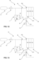
- an object of the invention is achieved by means of a fuel cell system comprising a reservoir of gaseous composition comprising at least partially hydrogen, the reservoir being connected to an inlet of a fuel cell, wherein the system comprises a device for recirculation according to the present invention, an outlet of the fuel cell being connected to the inlet of the device for recirculation and the outlet of the device for recirculation being connected to the inlet of the fuel cell.
- the fuel cell can be supplied with gaseous composition not only through the tank but also through the recirculation device.
- the hydrogen not consumed in the fuel cell is reintroduced into the fuel cell, limiting hydrogen losses and thus increasing the efficiency of the system.
- the system comprises a water separator in fluid connection with the outlet of the fuel cell and with the inlet of the device for recirculation. Thanks to the water separator, it is possible to extract water from the gaseous composition leaving the fuel cell before this composition is introduced into the device for recirculation. This prevents too much water from being introduced into the device for recirculation.
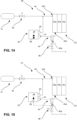
- the system comprises a relief valve in fluid connection with the discharge outlet of the water separator.
- the relief valve allows water to be discharged while preventing backflow.
- the valve advantageously comprises a sensor which allows the quantity of water in the water separator to be measured. When a certain water level is reached, the relief valve is opened and the water is discharged.
- the regulating inlet of the recirculation device is in fluid connection with the reservoir. This allows the gas contained in the reservoir to be introduced into the recirculation device and the pressure acting on the shaft seals of this device to be equalized. By equalizing the pressure, premature wear of the seals can be avoided.
- the discharge outlet of the recirculation device is fluidically connected to the discharge outlet of the water separator. This allows water that may form in the recirculation device to be discharged.
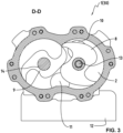
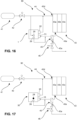
- Pumping chamber 2 is designed to accommodate two pistons with nozzles 8 and 9 (see Figure 3 ) driven in rotation by a first rotary shaft 13 and a second rotary shaft 14 supported by bearings 15 and 16, respectively located in the gear chamber cover 5 and in the gear chamber 4.
- the rotating shaft 13 of the claw piston 8 represents the input shaft, while the shaft 14 of the claw piston 9 forms the output shaft.
- the rotating shaft 13 is configured to be driven by an electric motor in a manner known to a person skilled in the art and which will not be detailed here.
- the drive of the second rotary shaft 14 of the claw piston 9 and its necessary synchronization with the first rotary shaft 13 of the claw piston 8 is carried out by means of a drive system comprising two toothed wheels 17 and 18 which mesh between the two bearings 15 and 16.
- the gear chamber 4 contains a lubricating liquid. It is advantageous, for the use of the device 1 for the recirculation of a composition containing hydrogen, to provide that the lubricating liquid is suitable for this field of application. It is in particular advantageous to provide a lubricating liquid which does not react with hydrogen and is compatible with the materials used for the membranes of a fuel cell.
Landscapes
- Engineering & Computer Science (AREA)
- Mechanical Engineering (AREA)
- General Engineering & Computer Science (AREA)
- Sustainable Development (AREA)
- Life Sciences & Earth Sciences (AREA)
- Sustainable Energy (AREA)
- Chemical & Material Sciences (AREA)
- Chemical Kinetics & Catalysis (AREA)
- Electrochemistry (AREA)
- General Chemical & Material Sciences (AREA)
- Manufacturing & Machinery (AREA)
- Fuel Cell (AREA)
- Applications Or Details Of Rotary Compressors (AREA)
Claims (15)
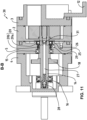
- Vorrichtung (1, 30) zur Umwälzung einer zumindest teilweise gasförmigen, wasserstoffhaltigen Zusammensetzung,wobei die Vorrichtung (1, 30) eine Trocken-Rotationspumpe ist, die eine erste rotierende Welle (13) und eine zweite rotierende Welle (14) umfasst, die einen ersten Kolben mit Klauen (8) beziehungsweise einen zweiten Kolben mit Klauen (9) innerhalb einer Pumpkammer (2) mit einer Einlassöffnung (11) und einer Auslassöffnung (10) für die gasförmige Zusammensetzung in Rotation versetzen, wobei die erste rotierende Welle (13) und die zweite rotierende Welle (14) derart konfiguriert sind, dass sie von einem Antriebssystem (17, 18) in Rotation versetzt werden, welches Antriebssystem (17, 18) in einer Getriebekammer (4) angeordnet ist,dadurch gekennzeichnet, dass die Vorrichtung (1, 30) ein erstes Dichtungspaar (19) und ein zweites Dichtungspaar (20) umfasst, die jeweils eine erste Wellendichtung (19a, 20a) und eine zweite Wellendichtung (19b, 20b) umfassen, wobei das erste Dichtungspaar (19) zwischen der Pumpkammer (2) und der Getriebekammer (4) um die erste rotierende Welle (13) angeordnet ist und das zweite Dichtungspaar (20) zwischen der Pumpkammer (2) und der Getriebekammer (4) um die zweite rotierende Welle (14) angeordnet ist und, dassdie Vorrichtung (1, 30) eine Druckausgleichskammer (25) umfasst, die fluidleitend mit einem Spalt (24), der zwischen der ersten Wellendichtung (19a, 20a) und der zweiten Wellendichtung (19b, 20b) des ersten und zweiten Dichtungspaars (19, 20) angeordnet ist, verbunden ist, um den Druck in dem Spalt (24) zu regulieren, und dassdie Getriebekammer (4) fluidleitend mit dem Spalt (24) verbunden ist, und dassdie Pumpkammer (2) durch eine Pulsationsdämpfungskammer (22) fluidleitend mit der ersten Wellendichtung (19a) des ersten Dichtungspaars (19) und mit der ersten Wellendichtung (20a) des zweiten Dichtungspaars (20) verbunden ist.
- Vorrichtung (1, 30) nach Anspruch 1, wobei zumindest eine der ersten Wellendichtung (19a) des ersten Dichtungspaars (19), der zweiten Wellendichtung (19b) des ersten Dichtungspaars (19), der ersten Wellendichtung (20a) des zweiten Dichtungspaars (20) und der zweiten Wellendichtung (20b) des zweiten Dichtungspaars (20) eine Lippendichtung ist.
- Vorrichtung (1, 30) nach einem der Ansprüche 1 oder 2, wobei die fluidleitende Verbindung zwischen dem Spalt (24) und der Getriebekammer (4) durch einen Druckausgleichskanal (27) in der ersten rotierenden Welle (13) und/oder in der zweiten rotierenden Welle (14) bewirkt wird.
- Vorrichtung (1, 30) nach Anspruch 3, wobei die Vorrichtung (1, 30) einen Schmierstofffilter (28) zwischen dem Druckausgleichskanal (27) und der Getriebekammer (4) umfasst.
- Vorrichtung (1, 30) nach einem der vorhergehenden Ansprüche, wobei ein Regulierungseinlass (29) bereitgestellt ist, um den Druck in der Druckausgleichskammer (25) von ausserhalb der Vorrichtung zu kontrollieren.
- Vorrichtung (30) nach einem der vorhergehenden Ansprüche, wobei die Pulsationsdämpfungskammer (22) über eine Membran (31), welche Membran durchlässig für Wasserstoffgas jedoch undurchlässig zumindest für Wassermoleküle in gasförmiger oder flüssiger Form ist, fluidleitend mit der Druckausgleichskammer verbunden ist.
- Vorrichtung (1, 30) nach einem der vorhergehenden Ansprüche, wobei die fluidleitende Verbindung zwischen der Pulsationsdämpfungskammer (22) und der Pumpkammer (2) zumindest teilweise die Form eines Labyrinths aufweist.
- Vorrichtung (1, 30) nach einem der vorhergehenden Ansprüche, wobei die Pulsationsdämpfungskammer (22) fluidleitend mit einem Abflussauslass (26) verbunden ist.
- Vorrichtung (1, 30) nach einem der vorhergehenden Ansprüche, wobei die Einlassöffnung (11) der Pumpkammer (2) derart orientiert ist, dass eine Drainage von Flüssigkeit durch den Einfluss der Schwerkraft ermöglicht wird.
- Vorrichtung (1, 30) nach einem der vorhergehenden Ansprüche und eingerichtet, den Druck einer zumindest teilweise gasförmigen, wasserstoffhaltigen Zusammensetzung am Einlass einer Brennstoffzelle in einem Bereich von bis zu 15 bar, vorzugsweise von 1.5 bis 5 bar absolut, zu erhöhen.
- Brennstoffzellensystem (40, 50, 60, 70) mit einem Reservoir einer gasförmigen Zusammensetzung (41), die zumindest teilweise Wasserstoff umfasst, welches Reservoir (41) mit einem Einlass (43d) einer Brennstoffzelle (43) verbunden ist und welches System
dadurch gekennzeichnet ist, dass
das System eine Vorrichtung zur Umwälzung (1, 30) nach einem der Ansprüche 1 bis 15 umfasst, wobei ein Auslass (43e) der Brennstoffzelle (43) mit der Einlassöffnung (11) der Vorrichtung zur Umwälzung (1, 30) verbunden ist und die Auslassöffnung (10) der Vorrichtung zur Umwälzung (1, 30) mit dem Einlass (43d) der Brennstoffzelle (43) verbunden ist. - Brennstoffzellensystem (40, 50, 60, 70, 80, 90) nach Anspruch 11, umfassend einen Wasserabscheider (45), der fluidleitend mit dem Auslass der Brennstoffzelle (43) und mit der Einlassöffnung der Vorrichtung zur Umwälzung (1, 30) verbunden ist.
- Brennstoffzellensystem (40, 50, 60, 70, 80, 90) nach Anspruch 12, umfassend ein Entlastungsventil (46), das fluidleitend mit dem Abflussauslass (45a) des Wasserabscheiders (45) verbunden ist.
- Brennstoffzellensystem (40, 50, 60, 70, 80, 90) nach einem der Ansprüche 11 bis 13, wobei der Regulierungseinlass (29) der Vorrichtung zur Umwälzung (1, 30) fluidleitend mit dem Reservoir (41) verbunden ist.
- Brennstoffzellensystem (40, 50, 60, 70, 80, 90) nach einem der Ansprüche 11 bis 14, wobei der Abflussauslass (26) der Vorrichtung zur Umwälzung (1, 30) fluidleitend mit dem Abflussauslass (45a) des Wasserabscheiders (45) verbunden ist.
Priority Applications (1)
| Application Number | Priority Date | Filing Date | Title |
|---|---|---|---|
| PL20706432.0T PL4107367T3 (pl) | 2020-02-17 | 2020-02-17 | Urządzenie do recyrkulacji co najmniej częściowo gazowej mieszaniny zawierającej wodór i system ogniw paliwowych |
Applications Claiming Priority (1)
| Application Number | Priority Date | Filing Date | Title |
|---|---|---|---|
| PCT/EP2020/054026 WO2021164843A1 (fr) | 2020-02-17 | 2020-02-17 | Dispositif pour la recirculation d'une composition au moins partiellement gazeuse contenant de l'hydrogène et système de pile à combustible |
Publications (3)
| Publication Number | Publication Date |
|---|---|
| EP4107367A1 EP4107367A1 (de) | 2022-12-28 |
| EP4107367B1 true EP4107367B1 (de) | 2025-04-16 |
| EP4107367C0 EP4107367C0 (de) | 2025-04-16 |
Family
ID=69645947
Family Applications (1)
| Application Number | Title | Priority Date | Filing Date |
|---|---|---|---|
| EP20706432.0A Active EP4107367B1 (de) | 2020-02-17 | 2020-02-17 | Anordnung zur umwälzung eines zumindest teilweise gasförmigen, wasserstoff enthaltenden gemisches und brennstoffzellensystem |
Country Status (12)
| Country | Link |
|---|---|
| US (1) | US11959478B2 (de) |
| EP (1) | EP4107367B1 (de) |
| JP (1) | JP7486587B2 (de) |
| KR (1) | KR102821839B1 (de) |
| CN (1) | CN115427661B (de) |
| AU (1) | AU2020430802B2 (de) |
| BR (1) | BR112022013016B1 (de) |
| CA (1) | CA3163986A1 (de) |
| ES (1) | ES3031238T3 (de) |
| PL (1) | PL4107367T3 (de) |
| TW (1) | TWI862784B (de) |
| WO (1) | WO2021164843A1 (de) |
Family Cites Families (17)
| Publication number | Priority date | Publication date | Assignee | Title |
|---|---|---|---|---|
| GB1484994A (en) * | 1973-09-03 | 1977-09-08 | Svenska Rotor Maskiner Ab | Shaft seal system for screw compressors |
| JPS6230387A (ja) * | 1985-07-12 | 1987-02-09 | Anretsuto:Kk | 炭酸ガスレ−ザ光線発振器用ル−ツブロワ− |
| JP3344825B2 (ja) * | 1994-05-24 | 2002-11-18 | 栃木富士産業株式会社 | スクリュー式過給機のシール装置 |
| BE1010915A3 (nl) * | 1997-02-12 | 1999-03-02 | Atlas Copco Airpower Nv | Inrichting voor het afdichten van een rotoras en schroefcompressor voorzien van dergelijke inrichting. |
| GB9708397D0 (en) * | 1997-04-25 | 1997-06-18 | Boc Group Plc | Improvements in vacuum pumps |
| DE10065587B4 (de) * | 2000-12-28 | 2007-01-18 | B&V Industrietechnik Gmbh | Abdichtungsvorrichtung für rotierende Wellen, insbesondere Stevenrohrabdichtung für Schiffe |
| US6783322B2 (en) * | 2002-04-23 | 2004-08-31 | Roper Holdings, Inc. | Pump system with variable-pressure seal |
| JP2006177299A (ja) * | 2004-12-24 | 2006-07-06 | Toyota Industries Corp | 電動ポンプ |
| JP2007115543A (ja) | 2005-10-20 | 2007-05-10 | Toyota Motor Corp | 燃料電池のオフガス燃焼装置、燃料電池システム、オフガス燃焼部のパージ方法 |
| JP4559343B2 (ja) * | 2005-11-09 | 2010-10-06 | 株式会社神戸製鋼所 | スクリュ圧縮機 |
| JP5046379B2 (ja) * | 2007-03-30 | 2012-10-10 | アネスト岩田株式会社 | オイルフリーロータリコンプレッサのロータ軸シール装置 |
| JP5332354B2 (ja) | 2008-07-07 | 2013-11-06 | トヨタ自動車株式会社 | ポンプ装置および燃料電池システム |
| KR101310490B1 (ko) * | 2009-05-20 | 2013-09-24 | 가부시키가이샤 아루박 | 드라이 진공 펌프 |
| JP6826512B2 (ja) * | 2017-09-06 | 2021-02-03 | 株式会社神戸製鋼所 | 圧縮装置 |
| DE202018004819U1 (de) * | 2018-10-18 | 2018-11-21 | Doris Korthaus | Rotierende Verdrängerpumpe mit Gleitringdichtung |
| CN110319004A (zh) * | 2019-07-15 | 2019-10-11 | 烟台菱辰能源有限公司 | 一种爪式氢气循环泵 |
| JP7491561B2 (ja) * | 2020-08-07 | 2024-05-28 | 地方独立行政法人東京都立産業技術研究センター | 殺菌装置および殺菌方法 |
-
2020
- 2020-02-17 KR KR1020227032133A patent/KR102821839B1/ko active Active
- 2020-02-17 WO PCT/EP2020/054026 patent/WO2021164843A1/fr not_active Ceased
- 2020-02-17 JP JP2022543092A patent/JP7486587B2/ja active Active
- 2020-02-17 AU AU2020430802A patent/AU2020430802B2/en active Active
- 2020-02-17 PL PL20706432.0T patent/PL4107367T3/pl unknown
- 2020-02-17 ES ES20706432T patent/ES3031238T3/es active Active
- 2020-02-17 EP EP20706432.0A patent/EP4107367B1/de active Active
- 2020-02-17 CN CN202080096203.9A patent/CN115427661B/zh active Active
- 2020-02-17 US US17/791,053 patent/US11959478B2/en active Active
- 2020-02-17 CA CA3163986A patent/CA3163986A1/fr active Pending
- 2020-02-17 BR BR112022013016-3A patent/BR112022013016B1/pt active IP Right Grant
-
2021
- 2021-02-05 TW TW110104454A patent/TWI862784B/zh active
Also Published As
| Publication number | Publication date |
|---|---|
| TWI862784B (zh) | 2024-11-21 |
| AU2020430802B2 (en) | 2025-10-02 |
| CN115427661A (zh) | 2022-12-02 |
| KR20220166268A (ko) | 2022-12-16 |
| BR112022013016A2 (pt) | 2022-09-06 |
| EP4107367A1 (de) | 2022-12-28 |
| US11959478B2 (en) | 2024-04-16 |
| JP2023516546A (ja) | 2023-04-20 |
| KR102821839B1 (ko) | 2025-06-17 |
| CN115427661B (zh) | 2025-09-19 |
| TW202136646A (zh) | 2021-10-01 |
| WO2021164843A1 (fr) | 2021-08-26 |
| CA3163986A1 (fr) | 2021-08-26 |
| PL4107367T3 (pl) | 2025-06-16 |
| JP7486587B2 (ja) | 2024-05-17 |
| BR112022013016B1 (pt) | 2024-01-02 |
| ES3031238T3 (en) | 2025-07-07 |
| US20230013325A1 (en) | 2023-01-19 |
| EP4107367C0 (de) | 2025-04-16 |
| AU2020430802A1 (en) | 2022-07-21 |
Similar Documents
| Publication | Publication Date | Title |
|---|---|---|
| CA2671839C (fr) | Procede et systeme de lubrification d'une turbomachine | |
| EP2494643B1 (de) | Verfahren zur erkennung des versiegelten zustandes einer brennstoffzelle | |
| EP1018774A1 (de) | Gasspülverfahren des Gaskreislaufes einer Brennstoffzelle und Vorrichtung zur Durchführung des Verfahrens | |
| FR2993614A1 (fr) | Procede et dispositif de pompage d'une chambre de procedes | |
| CA2738093A1 (fr) | Procede et systeme de lubrification d'une turbomachine | |
| EP0368122A1 (de) | Mehrstufige Roots-Vakuumpumpe | |
| EP3017492A1 (de) | Verfahren zum herunterfahren eines systems mit einem brennstoffzellenstapel und system mit einem brennstoffzellenstapel | |
| FR2675213A1 (fr) | Systeme formant barriere pour l'huile de lubrification des paliers d'un compresseur centrifuge muni de joints d'etancheite a labyrinthe installe dans un environnement confine. | |
| CA2858158A1 (fr) | Systeme pour assurer l'etancheite entre une enceinte d'huile et un volume exterieur attenant et turbomachine equipee d'un tel systeme d'etancheite | |
| EP2402613A1 (de) | Trockenvakuumpumpe | |
| EP4107367B1 (de) | Anordnung zur umwälzung eines zumindest teilweise gasförmigen, wasserstoff enthaltenden gemisches und brennstoffzellensystem | |
| FR2538457A1 (fr) | Circuit de carburant pour moteur a combustion interne | |
| EP3093498A1 (de) | Mikrogebläse mit verbesserter abdichtung der motorachse für beatmungsgerät | |
| FR3053081A1 (fr) | Circuit de depollution a uree comprenant un clapet a double siege assurant selectivement le degazage ou la recirculation de la solution aqueuse d’uree | |
| FR3061361A1 (fr) | Systeme electrochimique a pile a combustible comportant un dispositif de regulation de pression a detendeur | |
| FR3112578A3 (fr) | Pompe à vide à palettes, détecteur et installation de lyophilisation | |
| EP3340354B1 (de) | Elektrochemisches system mit brennstoffzelle, das eine vorrichtung zum einstellen des drucks mit expansionsventil umfasst | |
| FR3118649A3 (fr) | Pompe à vide rotative à palettes avec ensemble à lest de gaz | |
| FR2917902A1 (fr) | Procede et dispositif de securisation passive d'un groupe electrogene embarque a pile a combustible avec regulation depressurisee ameliorant l'efficacite des purges | |
| FR3079886A1 (fr) | Pompe a vide de type seche | |
| FR3152195A1 (fr) | Méthode de pilotage d’un système électrochimique et système électrochimique associé | |
| FR2917901A1 (fr) | Procede et dispositif de securisation passive d'un groupe electrogene embarque a pile a combustible. | |
| FR3071549A1 (fr) | Enceinte lubrifiee de moteur comprenant un systeme de depressurisation ameliore | |
| WO2025168832A1 (fr) | Compresseur centrifuge avec une alimentation auxiliaire en adjuvant | |
| FR3119209A1 (fr) | Pompe à vide de type sèche et groupe de pompage |
Legal Events
| Date | Code | Title | Description |
|---|---|---|---|
| STAA | Information on the status of an ep patent application or granted ep patent |
Free format text: STATUS: UNKNOWN |
|
| STAA | Information on the status of an ep patent application or granted ep patent |
Free format text: STATUS: THE INTERNATIONAL PUBLICATION HAS BEEN MADE |
|
| PUAI | Public reference made under article 153(3) epc to a published international application that has entered the european phase |
Free format text: ORIGINAL CODE: 0009012 |
|
| STAA | Information on the status of an ep patent application or granted ep patent |
Free format text: STATUS: REQUEST FOR EXAMINATION WAS MADE |
|
| 17P | Request for examination filed |
Effective date: 20220912 |
|
| AK | Designated contracting states |
Kind code of ref document: A1 Designated state(s): AL AT BE BG CH CY CZ DE DK EE ES FI FR GB GR HR HU IE IS IT LI LT LU LV MC MK MT NL NO PL PT RO RS SE SI SK SM TR |
|
| DAV | Request for validation of the european patent (deleted) | ||
| DAX | Request for extension of the european patent (deleted) | ||
| GRAP | Despatch of communication of intention to grant a patent |
Free format text: ORIGINAL CODE: EPIDOSNIGR1 |
|
| STAA | Information on the status of an ep patent application or granted ep patent |
Free format text: STATUS: GRANT OF PATENT IS INTENDED |
|
| INTG | Intention to grant announced |
Effective date: 20241023 |
|
| GRAS | Grant fee paid |
Free format text: ORIGINAL CODE: EPIDOSNIGR3 |
|
| GRAA | (expected) grant |
Free format text: ORIGINAL CODE: 0009210 |
|
| STAA | Information on the status of an ep patent application or granted ep patent |
Free format text: STATUS: THE PATENT HAS BEEN GRANTED |
|
| AK | Designated contracting states |
Kind code of ref document: B1 Designated state(s): AL AT BE BG CH CY CZ DE DK EE ES FI FR GB GR HR HU IE IS IT LI LT LU LV MC MK MT NL NO PL PT RO RS SE SI SK SM TR |
|
| REG | Reference to a national code |
Ref country code: GB Ref legal event code: FG4D Free format text: NOT ENGLISH |
|
| REG | Reference to a national code |
Ref country code: CH Ref legal event code: EP |
|
| REG | Reference to a national code |
Ref country code: IE Ref legal event code: FG4D Free format text: LANGUAGE OF EP DOCUMENT: FRENCH |
|
| REG | Reference to a national code |
Ref country code: DE Ref legal event code: R096 Ref document number: 602020049499 Country of ref document: DE |
|
| U01 | Request for unitary effect filed |
Effective date: 20250502 |
|
| U07 | Unitary effect registered |
Designated state(s): AT BE BG DE DK EE FI FR IT LT LU LV MT NL PT RO SE SI Effective date: 20250509 |
|
| REG | Reference to a national code |
Ref country code: ES Ref legal event code: FG2A Ref document number: 3031238 Country of ref document: ES Kind code of ref document: T3 Effective date: 20250707 |
|
| PG25 | Lapsed in a contracting state [announced via postgrant information from national office to epo] |
Ref country code: NO Free format text: LAPSE BECAUSE OF FAILURE TO SUBMIT A TRANSLATION OF THE DESCRIPTION OR TO PAY THE FEE WITHIN THE PRESCRIBED TIME-LIMIT Effective date: 20250716 Ref country code: GR Free format text: LAPSE BECAUSE OF FAILURE TO SUBMIT A TRANSLATION OF THE DESCRIPTION OR TO PAY THE FEE WITHIN THE PRESCRIBED TIME-LIMIT Effective date: 20250717 |
|
| PG25 | Lapsed in a contracting state [announced via postgrant information from national office to epo] |
Ref country code: HR Free format text: LAPSE BECAUSE OF FAILURE TO SUBMIT A TRANSLATION OF THE DESCRIPTION OR TO PAY THE FEE WITHIN THE PRESCRIBED TIME-LIMIT Effective date: 20250416 |
|
| PG25 | Lapsed in a contracting state [announced via postgrant information from national office to epo] |
Ref country code: RS Free format text: LAPSE BECAUSE OF FAILURE TO SUBMIT A TRANSLATION OF THE DESCRIPTION OR TO PAY THE FEE WITHIN THE PRESCRIBED TIME-LIMIT Effective date: 20250716 |
|
| PG25 | Lapsed in a contracting state [announced via postgrant information from national office to epo] |
Ref country code: IS Free format text: LAPSE BECAUSE OF FAILURE TO SUBMIT A TRANSLATION OF THE DESCRIPTION OR TO PAY THE FEE WITHIN THE PRESCRIBED TIME-LIMIT Effective date: 20250816 |
|
| PG25 | Lapsed in a contracting state [announced via postgrant information from national office to epo] |
Ref country code: SM Free format text: LAPSE BECAUSE OF FAILURE TO SUBMIT A TRANSLATION OF THE DESCRIPTION OR TO PAY THE FEE WITHIN THE PRESCRIBED TIME-LIMIT Effective date: 20250416 |
|
| PG25 | Lapsed in a contracting state [announced via postgrant information from national office to epo] |
Ref country code: CZ Free format text: LAPSE BECAUSE OF FAILURE TO SUBMIT A TRANSLATION OF THE DESCRIPTION OR TO PAY THE FEE WITHIN THE PRESCRIBED TIME-LIMIT Effective date: 20250416 |
|
| PG25 | Lapsed in a contracting state [announced via postgrant information from national office to epo] |
Ref country code: SK Free format text: LAPSE BECAUSE OF FAILURE TO SUBMIT A TRANSLATION OF THE DESCRIPTION OR TO PAY THE FEE WITHIN THE PRESCRIBED TIME-LIMIT Effective date: 20250416 |