EP4105730A1 - Vorrichtung zum herstellen von hologrammen im kontaktkopieverfahren mit hoher beugungseffizienz - Google Patents
Vorrichtung zum herstellen von hologrammen im kontaktkopieverfahren mit hoher beugungseffizienz Download PDFInfo
- Publication number
- EP4105730A1 EP4105730A1 EP22179192.4A EP22179192A EP4105730A1 EP 4105730 A1 EP4105730 A1 EP 4105730A1 EP 22179192 A EP22179192 A EP 22179192A EP 4105730 A1 EP4105730 A1 EP 4105730A1
- Authority
- EP
- European Patent Office
- Prior art keywords
- recording material
- coherent light
- hologram master
- hologram
- holographic recording
- Prior art date
- Legal status (The legal status is an assumption and is not a legal conclusion. Google has not performed a legal analysis and makes no representation as to the accuracy of the status listed.)
- Granted
Links
Images
Classifications
-
- G—PHYSICS
- G03—PHOTOGRAPHY; CINEMATOGRAPHY; ANALOGOUS TECHNIQUES USING WAVES OTHER THAN OPTICAL WAVES; ELECTROGRAPHY; HOLOGRAPHY
- G03H—HOLOGRAPHIC PROCESSES OR APPARATUS
- G03H1/00—Holographic processes or apparatus using light, infrared or ultraviolet waves for obtaining holograms or for obtaining an image from them; Details peculiar thereto
- G03H1/04—Processes or apparatus for producing holograms
- G03H1/20—Copying holograms by holographic, i.e. optical means
- G03H1/202—Contact copy when the reconstruction beam for the master H1 also serves as reference beam for the copy H2
-
- G—PHYSICS
- G03—PHOTOGRAPHY; CINEMATOGRAPHY; ANALOGOUS TECHNIQUES USING WAVES OTHER THAN OPTICAL WAVES; ELECTROGRAPHY; HOLOGRAPHY
- G03H—HOLOGRAPHIC PROCESSES OR APPARATUS
- G03H1/00—Holographic processes or apparatus using light, infrared or ultraviolet waves for obtaining holograms or for obtaining an image from them; Details peculiar thereto
- G03H1/02—Details of features involved during the holographic process; Replication of holograms without interference recording
-
- G—PHYSICS
- G03—PHOTOGRAPHY; CINEMATOGRAPHY; ANALOGOUS TECHNIQUES USING WAVES OTHER THAN OPTICAL WAVES; ELECTROGRAPHY; HOLOGRAPHY
- G03H—HOLOGRAPHIC PROCESSES OR APPARATUS
- G03H1/00—Holographic processes or apparatus using light, infrared or ultraviolet waves for obtaining holograms or for obtaining an image from them; Details peculiar thereto
- G03H1/02—Details of features involved during the holographic process; Replication of holograms without interference recording
- G03H1/0236—Form or shape of the hologram when not registered to the substrate, e.g. trimming the hologram to alphanumerical shape
-
- G—PHYSICS
- G03—PHOTOGRAPHY; CINEMATOGRAPHY; ANALOGOUS TECHNIQUES USING WAVES OTHER THAN OPTICAL WAVES; ELECTROGRAPHY; HOLOGRAPHY
- G03H—HOLOGRAPHIC PROCESSES OR APPARATUS
- G03H1/00—Holographic processes or apparatus using light, infrared or ultraviolet waves for obtaining holograms or for obtaining an image from them; Details peculiar thereto
- G03H1/04—Processes or apparatus for producing holograms
- G03H1/0486—Improving or monitoring the quality of the record, e.g. by compensating distortions, aberrations
-
- G—PHYSICS
- G03—PHOTOGRAPHY; CINEMATOGRAPHY; ANALOGOUS TECHNIQUES USING WAVES OTHER THAN OPTICAL WAVES; ELECTROGRAPHY; HOLOGRAPHY
- G03H—HOLOGRAPHIC PROCESSES OR APPARATUS
- G03H1/00—Holographic processes or apparatus using light, infrared or ultraviolet waves for obtaining holograms or for obtaining an image from them; Details peculiar thereto
- G03H1/0005—Adaptation of holography to specific applications
- G03H1/0011—Adaptation of holography to specific applications for security or authentication
-
- G—PHYSICS
- G03—PHOTOGRAPHY; CINEMATOGRAPHY; ANALOGOUS TECHNIQUES USING WAVES OTHER THAN OPTICAL WAVES; ELECTROGRAPHY; HOLOGRAPHY
- G03H—HOLOGRAPHIC PROCESSES OR APPARATUS
- G03H1/00—Holographic processes or apparatus using light, infrared or ultraviolet waves for obtaining holograms or for obtaining an image from them; Details peculiar thereto
- G03H1/02—Details of features involved during the holographic process; Replication of holograms without interference recording
- G03H2001/0208—Individual components other than the hologram
-
- G—PHYSICS
- G03—PHOTOGRAPHY; CINEMATOGRAPHY; ANALOGOUS TECHNIQUES USING WAVES OTHER THAN OPTICAL WAVES; ELECTROGRAPHY; HOLOGRAPHY
- G03H—HOLOGRAPHIC PROCESSES OR APPARATUS
- G03H2222/00—Light sources or light beam properties
- G03H2222/10—Spectral composition
- G03H2222/12—Single or narrow bandwidth source, e.g. laser, light emitting diode [LED]
-
- G—PHYSICS
- G03—PHOTOGRAPHY; CINEMATOGRAPHY; ANALOGOUS TECHNIQUES USING WAVES OTHER THAN OPTICAL WAVES; ELECTROGRAPHY; HOLOGRAPHY
- G03H—HOLOGRAPHIC PROCESSES OR APPARATUS
- G03H2227/00—Mechanical components or mechanical aspects not otherwise provided for
- G03H2227/04—Production line for mass production
-
- G—PHYSICS
- G03—PHOTOGRAPHY; CINEMATOGRAPHY; ANALOGOUS TECHNIQUES USING WAVES OTHER THAN OPTICAL WAVES; ELECTROGRAPHY; HOLOGRAPHY
- G03H—HOLOGRAPHIC PROCESSES OR APPARATUS
- G03H2227/00—Mechanical components or mechanical aspects not otherwise provided for
- G03H2227/05—Support holding the holographic record
Definitions
- the invention relates to a device for producing holograms using the contact copying method, in particular holograms with a high diffraction efficiency.
- Security features are formed in value and/or security documents which are intended to ensure that the authenticity and authenticity of the corresponding value and/or security document can be checked. Such features are referred to as security features.
- Holograms represent a group of security features that are used for this. Holograms can basically be divided into two different categories. On the one hand there are so-called thin holograms in which the holographic information is stored in a layer whose layer thickness is of the order of magnitude of the wavelength of the light or electromagnetic radiation with which the hologram can be reconstructed. The holographic information is often stored in the form of a surface relief on the surface. These holograms are then referred to as surface holograms.
- holograms store the holographic information in the volume of a recording material, with a layer thickness of the storage area corresponding to a multiple of the wavelength of the light or electromagnetic radiation with which the hologram can be reconstructed.
- These holograms are also referred to as volume holograms.
- volume holograms are stored in a photosensitive material by means of exposure.
- a production method for producing volume reflection holograms in particular uses a hologram master in front of which a holographic recording material is arranged.
- coherent light is radiated through the holographic recording material onto the hologram master, which at least partially reflects the light, for example reflecting it or diffracting it in reflection.
- this interferes with the Hologram master reflected light, eg diffracted or reflected in reflection, with the coherent light that is radiated through the recording material onto the hologram master.
- the interference pattern that forms in the hologram recording material is stored in the hologram recording material, which is usually a photosensitive material, particularly preferably a photopolymer.
- the physical and/or chemical changes in the photosensitive material are then fixed so that the photosensitive material becomes insensitive to radiation and the hologram can then be reconstructed upon exposure to light.
- holographic recording material is preferably brought into contact with the hologram master during the exposure process in order to avoid a relative movement of the recording material with respect to the hologram master, such an exposure method is also called a contact copying method.
- the holographic recording material is supplied to and removed from the exposure process either in the form of sheets or as roll material.
- a quality of the hologram produced in this way is shown by how high the diffraction efficiency of the hologram produced in the contact copying process is. The higher the diffraction efficiency, the better the copy produced. It will be appreciated by those skilled in the art that diffraction efficiency is limited in part by the quality of the hologram master. However, it has been shown that when a large number of holograms are produced using the contact copying method, the quality of the holograms produced in this way varies. Such a variation is undesirable for holograms that are to be used as security features.
- the invention is therefore based on the technical task of creating a device and a method for producing holograms using the contact copying method, which ensure the highest possible constant high diffraction efficiency of the holograms produced.
- the invention is based on the basic idea that the reaction conditions in the holographic recording material must be kept as optimal as possible.
- the coherent radiation which is usually laser radiation
- high thermal losses occur, some of which are then introduced into a reaction chamber in which the recording material is exposed, thermal changes in particular occur which, according to the inventors are presumed to be responsible for the variation and, in particular, deterioration of the diffraction efficiency during the manufacture of a variety of holograms.
- a hologram master can also be subject to wear, the associated changes in diffraction efficiency can be observed on a completely different, much longer time scale than the otherwise observed changes in diffraction efficiency of holograms produced using the contact copying method.
- a volume hologram is a hologram in which the holographic information is stored in a volume area whose strength is greater than a multiple of the wavelength of the electromagnetic radiation with which the hologram can be reconstructed.
- the thickness of this layer is at least five to fifteen times the wavelength of the electromagnetic radiation used for recording.
- a method for producing holograms, in which a holographic recording material is arranged adjacent to a hologram master, is referred to as a contact copying method.
- the electromagnetic radiation used for recording is radiated through the holographic recording material onto the hologram master, which reflects part of this radiation back into the holographic recording material, for example reflecting or reflectively diffracting it. That between the irradiated electromagnetic Radiation and the interference pattern produced by the radiation reflected back by the hologram master is stored in the holographic recording material in the form of local changes, in particular in the form of changes in the refractive index. This applies in particular to photopolymers. In other recording materials, storage can also take place in the form of blackening.
- a hologram master is usually itself a volume reflection hologram and can be produced in any way. In other embodiments, however, the hologram master can also be a faceted surface, for example a blazed grating or the like.
- the holograms produced are transmission holograms which are produced using the contact copying method in which the hologram master is transparent to the electromagnetic radiation used for exposure and only part of the electromagnetic radiation is diffracted.
- the light is irradiated through the hologram master into the holographic recording material arranged on the side opposite to the irradiation side in contact with the hologram master.
- Part of the electromagnetic radiation radiating through the hologram master is not diffracted, while another part is diffracted. This again creates an interference pattern in the holographic recording material, which forms a volume transmission hologram.
- a room or chamber in which the exposure of the holographic recording material takes place is referred to as a reaction chamber.
- the reaction chamber is sealed from an environment in a radiation-tight manner to prevent exposure to ambient light or other radiation which may cause changes in the holographic recording material.
- the radiation-tight shielding is also generally designed in such a way that it also prevents dirt and dust particles from entering the reaction chamber, which could soil and/or damage the hologram master and/or the holographic recording material.
- Electromagnetic dipole radiation is regarded as light, the wavelength of which is in the visible wavelength range, in the UV wavelength range or in the IR wavelength range.
- a heat pipe is a device for transporting heat, i.e. thermal energy.
- a working medium is enclosed in the heat pipe and is in a liquid state of aggregation at one end. At this heated end, the working medium absorbs thermal energy and thereby cools the area around the heated end. The working medium is thereby converted into the gaseous state of aggregation and spreads out in the heat pipe. At a cooled end, the working medium releases thermal energy and carries out a phase transition back to the liquid state. In an embodiment referred to as a two-phase siphon, the working medium then reaches the heated end driven by gravity. In a so-called heat pipe embodiment, the working medium is transported back via capillary forces.
- Transparent is a medium for light if an image according to geometric optics is possible through the medium with the light.
- the transparent medium does not appreciably absorb the light and the transparent medium does not diffusely scatter the light. Absorption of the light in connection with exposure processes in a photosensitive material is not taken into account here.
- the cooling device flows a cooling fluid into the reaction chamber. Cooling fluid, which is gaseous, thus flows into the reaction chamber. Cool, dry, dust-free air is best suited for this. In particular with a gas-tight design of the reaction chamber, however, other gases, such as CO 2 , nitrogen, can also be used.
- the reaction chamber is preferably designed in such a way that the cooling fluid flows into the reaction chamber in a lower region.
- the reaction chamber is also preferably designed in such a way that heated cooling fluid flows out of the reaction chamber in an upper region of the latter.
- the cooling fluid is particularly preferably conducted in a closed circuit.
- the cooled cooling fluid flows into the reaction chamber in a lower area and flows out of it in an upper area of the reaction chamber and is guided in a closed cooling circuit and cooled before it flows back into the reaction chamber in the lower area.
- the cooling device comprises at least one heat pipe.
- a working medium in a liquid state of aggregation is located in a heat pipe in a first section, which protrudes into the reaction chamber.
- the working medium is heated via the walls of the heat pipe and thus extracts thermal energy from the reaction chamber.
- the working medium is partially converted into a gaseous state and moves into a second area of the heat pipe. In this area, thermal energy is released again via the surface of the heat pipe to an energy sink, as a result of which the aggregate state of the working medium is converted from the gaseous back to the liquid state.
- thermosiphon In an embodiment referred to as a two-phase thermosiphon, the liquid working medium, driven by gravity, moves back into the first region in order to be heated again there in the reaction chamber.
- a heat pipe In an embodiment referred to as a heat pipe, in which, for example, a copper wire mesh is located inside the heat pipe, the return transport is driven by capillary forces. This cyclical process takes place in the heat pipe without moving any mechanical components.
- a heat pipe is therefore very low-wear and low-maintenance. Furthermore, a heat pipe works free of vibration and shock.
- At least one element of the cooling device is thermally conductively connected to the hologram master in order to cool the hologram master.
- This can be, for example, a cooling register or a thermally conductive plate, for example made of a thermally conductive metal, which is in contact with a heat exchanger.
- the hologram master can be integrated into a holder, which in turn is traversed by pipelines through which a cooling fluid flows.
- the cooling fluid can be liquid or gaseous.
- the hologram master and/or other components of the reaction chamber to be cooled are arranged in thermally conductive contact with the at least one heat pipe and/or a further or other element of the cooling device.
- the cooling device preferably gives off the heat which it has removed from the reaction chamber to an energy sink. As a result, the thermal energy is completely dissipated from the device. This prevents the device from heating up as a whole during the production of holograms.
- the energy sink is a secondary fluid flow.
- This is, for example, a refrigeration cycle in which water is used as the secondary cooling fluid.
- the secondary cooling fluid can also be a cold gas.
- the energy sink can also be a material that changes its physical state when heated, for example dry ice or water-based ice.
- the energy sink can also additionally or alternatively include or be a refrigerating machine.
- a device 1 for producing holograms using the contact copying method comprises a multiplicity of chambers 10.
- holographic recording material 20 is provided on a supply roll 25.
- the holographic recording material 20 typically includes a photopolymer layer 21.
- the holographic recording material 20 typically includes a carrier layer 22 to which the photopolymer layer 21 is applied.
- a protective layer 23 can be provided on the side of the photopolymer layer 21 facing away from the carrier layer 22 .
- Both the carrier layer 22 and the protective layer 23 are transparent, ie imaging according to geometrical optics is possible through them. This also means that there is no appreciable absorption and/or diffuse scattering in the layers.
- the holographic recording material 20 is fed through a reaction chamber 12, a UV fixing chamber 13 and a thermal fixing chamber 14 into a storage chamber 15 where the holographic recording material 20, after holograms have been exposed thereon, is rolled up on a storage roll 35 and taken up.
- the transport of the holographic recording material is effected by a transport device 30, which drives, for example, the storage roller 35 and optionally further transport rollers 31.
- the transport device 30 for feeding and removing the holographic recording material into the reaction chamber 12 can also be designed in any other way.
- the individual chambers 10, in particular the feed chamber 11, the reaction chamber 12 and the UV fixing chamber 13, protect the holographic recording material from the irradiation of light from outside the device 1. They also protect the holographic recording material 20 and the devices located therein from other environmental influences , such as dust and dirt in particular.
- the holographic recording material 20 is arranged adjacent to a hologram master 40 in the reaction chamber 12 .
- the hologram master 40 is preferably a master volume reflection hologram 41.
- the holographic Recording material 20 brought into contact with an upper side 46 of the hologram master 40, for example by means of a movable doctor blade 50 with an underside 27 of the holographic recording material 20.
- the squeegee 50 is connected to a squeegee drive and guide device 51, which is only indicated schematically here.
- Coherent light 81 is generated in a coherent light source 60 in a laser chamber 16 .
- the coherent light source 60 is a laser 61.
- the coherent light 81 enters an optics chamber 17 from the laser chamber 16 .
- the coherent light 81 is expanded, shaped and deflected by means of beam shaping and guiding optics 70 and guided through the holographic recording material 20 onto the hologram master 40 .
- the beam shaping and guiding optics 70 are located in an optics chamber 17 which is formed above the reaction chamber 12 and the laser chamber 16 .
- the coherent light 81 of the coherent light source 60 used for exposure thus enters the reaction chamber 12 from the optics chamber 17 .
- the coherent light 81 After the coherent light 81 has passed the holographic recording material 20, it hits the hologram master 40 and is at least partly reflected back there. If the hologram master 40 is in the form of a volume reflection hologram, the coherent light 81 is thrown back as diffracted light 82 .
- the coherent light can also be reflected at other hologram masters, for example if the hologram master is facetted, for example as a blazed grating or the like.
- the reflected, generally diffracted light 82 interferes in the holographic recording material 20 with the coherent light 81 radiated in for exposure. This causes local changes in the holographic recording material 20 .
- the holographic recording material 20 is in the form of a photopolymer, chemical reactions are triggered which lead to changes in the refractive index in the photopolymer layer 21, i.e. the holographic recording material 20.
- the interference structure stored in this way is referred to as a hologram.
- the exposure of the hologram in the holographic recording material 20 can take place simultaneously over a surface area or in a scanning manner, in that the coherent light 81 sweeps over the holographic recording material 20 and the hologram master 40 located underneath, for example linearly.
- the beam shaping and guiding optics 70 can optionally include a spatial light modulator 71 to adjust the intensity of the coherent light 81 used for exposure to modulate spatially. What is thereby achieved is that, for example in the case of a master hologram representing a homogeneous luminous surface, for example a diffuser, this luminous surface is locally differently “bright” exposed in the hologram. This makes it possible to customize the hologram.
- the hologram master can be designed to generate a single hologram or a plurality of holograms in a multiple copy during an exposure process.
- the holographic recording material 20 is not moved continuously but stepwise through the various chambers 10 by means of the transport device 30 .
- the holographic recording material 20 is first moved into the UV fixing chamber 13 and then into the thermal fixing chamber 14 .
- the UV fixing chamber 13 the holographic recording material is irradiated with ultraviolet rays.
- the holographic recording material is heated in the thermal fixing chamber 14, for example by means of infrared radiation.
- the effect in the two fixing chambers 13, 14 is that the holographic recording material loses its photosensitivity and at the same time the hologram is permanently stored in the holographic recording material 20 in the form of changes in the refractive index.
- other post-processing steps for developing and/or fixing the hologram may be necessary and provided for.
- a cooling device 100 is provided for this purpose.
- a cooling device 100 is shown schematically, which combines different cooling devices and/or cooling variants. It is clear to the person skilled in the art that other embodiments can only include one cooling variant, and optionally alternatively formed cooling variants.
- a cooling variant consists in that a cooling fluid 300 flows into the reaction chamber.
- the cooling fluid 300 is a cooled gas or gas mixture. This is particularly preferably anhydrous.
- the fluid 300 is preferably introduced into the reaction chamber 12 by means of a fluid inflow device 110 poured in.
- the fluid inflow device 110 comprises, for example, one or more supply fans 111 which convey the cooling fluid 300 to an inflow opening 112 .
- the cooling fluid 300 can be taken from the surroundings of the device 1 or can come from a reservoir 310, for example a compressed gas cylinder.
- the cooling device can comprise a cleaning and filter unit 116 .
- a drying unit 117 can preferably also be provided, by means of which the water contained in the fluid taken up from the environment is removed and/or condensed out.
- the cooling fluid 300 is preferably conducted past a heat exchanger unit 115 and cooled in relation to the environment.
- the cooling fluid 300 preferably flows into the reaction chamber 12 at the level of the hologram master 40 and/or the holographic recording material 20, so that the holographic recording material 20 and the hologram master 40 are cooled.
- a secondary cooling fluid 400 preferably flows through the heat exchanger unit 115 and absorbs the heat given off by the cooling fluid 300 and dissipates it to an energy sink 500 .
- This can be a chiller or a cooling water circuit.
- the illustrated embodiment of the cooling device 100 has a cooling register 120 as a further cooling variant, which is thermally conductively connected to the hologram master 40 directly or via a heat-conducting plate.
- the cooling register 120 preferably has the secondary cooling fluid 400 flowing through it, which releases the thermal energy absorbed by the hologram master to the energy sink 500 .
- the cooling device 100 additionally comprises a heat pipe 130 as a cooling variant.
- a working medium which collects as a liquid in a lower area 137 of the heat pipe.
- Heat is absorbed via the outer wall of the heat pipe, which protrudes into the reaction chamber 12, and the interior of the reaction chamber 12 is thus cooled.
- the heat causes a phase change in the working medium so that it becomes gaseous and reaches the upper region 136 in the heat pipe.
- thermal energy is transferred via the outer wall of the heat pipe delivered, so that a phase transition takes place in the working medium again and this again in the liquid state driven by gravity or due to capillary forces in the lower region 137 of the heat pipe 130 passes.
- the heat in the upper area 136 of the heat pipe 130 can be dissipated to the ambient air, for example, by means of a cooling fan 140 of the cooling device 100 .
- the heat pipe 130 can be cooled in the upper area by a cooling line 150 through which the secondary cooling fluid 400 flows.
- the different variants with which the illustrated cooling device 100 is configured can be used in any combination in order to cool the reaction chamber 12 .
- multiple inflow devices 110 and/or multiple heat pipes 130 and/or multiple cooling registers 120 can be provided.
- several cooling circuits can be provided for secondary cooling fluid.
- the cooling device can also have several cooling machines as energy sinks and/or additional or alternative cooling water circuits.
- the cooling register 120 can comprise a closed primary cooling fluid circuit (shown in dashed lines), which gives off its heat to the secondary cooling fluid 400 via a further heat exchanger unit 125, which is coupled to an energy sink 500 in the form of a refrigerator and/or a cooling water line or the like.
- the secondary cooling fluid 400 can be directly connected to a cooling water line, so that the cooling water is the secondary cooling fluid 400 .
- the secondary cooling fluid 400 will circulate in a closed cooling circuit and be cooled in the refrigeration machine or cooled by cooling water via a heat exchanger in which the secondary cooling fluid 400 releases its energy.
- one or more cooling registers through which the secondary cooling fluid 400 flows directly can also be provided in the upper region of the reaction chamber instead of the heat pipe 130 .
Landscapes
- Physics & Mathematics (AREA)
- General Physics & Mathematics (AREA)
- Holo Graphy (AREA)
Abstract
einen Hologrammmaster (40),
eine kohärente Lichtquelle (60) zum Erzeugen kohärenten Lichts (81),
eine Transproteinrichtung (30) zum Zu- und Abführen von holografischem Aufzeichnungsmaterial (20), so dass dieses für einen Belichtungsvorgang anliegend an und vor dem Hologrammmaster (40) angeordnet wird, und
eine Reaktionskammer (12), die den Hologrammmaster (40) umgibt und das holografische Aufzeichnungsmaterial (20) während des Belichtungsvorgangs vor Umgebungslicht und Fremdmaterial schützt, wobei das kohärente Licht der kohärenten Lichtquelle (60) während des Belichtungsvorgangs in die Reaktionskammer (12) eingestrahlt wird, so dass das kohärente Licht das anliegend an und vor dem Hologrammmaster (40) angeordnete holografische Aufzeichnungsmaterial (20) durchstrahlt und zumindest teilweise an dem Hologrammmaster (40) zurückgestrahlt wird, so dass im Innern des holografischen Aufzeichnungsmaterials (20) aufgrund von Interferenzen zwischen dem das holografische Aufzeichnungsmaterial (20) durchstrahlenden kohärenten Licht (81) und dem zumindest teilweise vom Hologrammmaster (40) zurückgestrahlten Licht (82) Änderungen herbeigeführt werden, die ein Hologramm ausbilden,
wobei eine Kühlvorrichtung (100) zum Abführen von Wärme aus der Reaktionskammer (12) ausgebildet ist.
Ferner betrifft die Erfindung ein Verfahren zum Herstellen von Hologrammen.
Description
- Die Erfindung betrifft eine Vorrichtung zum Herstellen von Hologrammen im Kontaktkopierverfahren, insbesondere von Hologrammen mit einer hohen Beugungseffizienz.
- In Wert- und/oder Sicherheitsdokumenten werden Merkmale ausgebildet, welche eine Überprüfbarkeit der Echtheit und Unverfälschtheit des entsprechenden Wert- und/oder Sicherheitsdokuments gewährleisteten sollen. Solche Merkmale werden als Sicherheitsmerkmale bezeichnet.
- Hologramme stellen eine Gruppe von Sicherheitsmerkmalen dar, die hierfür eingesetzt werden. Hologramme können grundsätzlich in zwei verschiedene Kategorien eingeteilt werden. Zum einen gibt es sogenannte dünne Hologramme, bei denen die holografische Information in einer Schicht gespeichert ist, deren Schichtstärke in der Größenordnung der Wellenlänge des Lichts bzw. der elektromagnetischen Strahlung liegt, mit der das Hologramm rekonstruiert werden kann. Häufig wird die holografische Information in Form eines Oberflächenreliefs an der Oberfläche gespeichert. Diese Hologramme werden dann als Oberflächenhologramme bezeichnet. Eine andere Klasse von Hologrammen, welche als sogenannte dicke Hologramme bezeichnet werden, speichern die holografische Information im Volumen eines Aufzeichnungsmaterials, wobei eine Schichtstärke des Speicherungsbereichs einem Vielfachen der Wellenlänge des Lichts bzw. der elektromagnetischen Strahlung entspricht, mit der das Hologramm rekonstruiert werden kann. Diese Hologramme werden auch als Volumenhologramme bezeichnet.
- Während Oberflächenhologramme beispielsweise in Kunststoffschichten eingeprägt werden können, werden Volumenhologramme mittels einer Belichtung in ein fotoempfindliches Material gespeichert. Ein Herstellungsverfahren zum Herstellen von insbesondere Volumenreflexionshologrammen nutzt einen Hologrammmaster, vor dem ein holografisches Aufzeichnungsmaterial angeordnet wird. Beim Aufzeichnen bzw. Belichten des Hologramms in das holografische Aufzeichnungsmaterial wird kohärentes Licht durch das holografische Aufzeichnungsmaterial hindurch auf den Hologrammmaster eingestrahlt, der das Licht zumindest teilweise zurückwirft, beispielsweise reflektiert oder in Reflexion beugt. Im holografischen Aufzeichnungsmaterial interferiert dieses vom Hologrammmaster zurückgeworfene, z.B. in Reflexion gebeugte oder zurückgespiegelte, Licht mit dem kohärenten Licht, das durch das Aufzeichnungsmaterial auf den Hologrammmaster eingestrahlt wird. Das sich in dem Hologrammaufzeichnungsmaterial ausbildende Interferenzmuster wird in dem Hologrammaufzeichnungsmaterial, welches in der Regel ein fotoempfindliches Material ist, besonders bevorzugt ein Fotopolymer, gespeichert. Die physikalischen und/oder chemischen Veränderungen in dem fotoempfindlichen Material werden anschließend fixiert, sodass das fotoempfindliche Material gegenüber Strahlung unempfindlich wird und das Hologramm anschließend bei Einstrahlung von Licht rekonstruiert werden kann.
- Da das holografische Aufzeichnungsmaterial während des Belichtungsvorgangs vorzugsweise in Kontakt mit dem Hologrammmaster gebracht wird, um eine Relativbewegung des Aufzeichnungsmaterials gegenüber dem Hologrammmaster zu vermeiden, wird ein solches Belichtungsverfahren auch Kontaktkopierverfahren genannt.
- Im Stand der Technik wird das holografische Aufzeichnungsmaterial entweder in Form von Bögen oder als Rollenmaterial dem Belichtungsprozess zu- und wieder abgeführt.
- Eine Qualität des so hergestellten Hologramms zeigt sich darin, wie hoch die Beugungseffizienz des in dem Kontaktkopierverfahren hergestellten Hologramms ist. Je höher die Beugungseffizienz ist, desto besser ist die hergestellte Kopie. Es versteht sich für den Fachmann, dass die Beugungseffizienz teilweise durch die Qualität des Hologrammmasters begrenzt ist. Es hat sich jedoch gezeigt, dass bei der Herstellung von einer Vielzahl von Hologrammen im Kontaktkopierverfahren die Qualität der so hergestellten Hologramme variiert. Eine solche Variation ist für Hologramme, die als Sicherheitsmerkmale eingesetzt werden sollen, unerwünscht.
- Der Erfindung liegt somit die technische Aufgabe zugrunde, eine Vorrichtung und ein Verfahren zur Herstellung von Hologrammen im Kontaktkopierverfahren zu schaffen, die eine möglichst gleichbleibende hohe Beugungseffizienz der hergestellten Hologramme gewährleisten.
- Die Aufgabe wird durch eine Vorrichtung mit den Merkmalen des Patentanspruchs 1 sowie ein Verfahren mit den Merkmalen des Patentanspruchs 8 gelöst. Vorteilhafte Ausführungsformen der Erfindung ergeben sich aus den Unteransprüchen.
- Die Erfindung basiert auf der Grundidee, dass die Reaktionsbedingungen in dem holografischen Aufzeichnungsmaterial möglichst optimal gehalten werden müssen. Während bei der Erzeugung der kohärenten Strahlung, welches in der Regel Laserstrahlung ist, hohe thermische Verluste auftreten, die dann teilweise in eine Reaktionskammer, in der die Belichtung des Aufzeichnungsmaterials stattfindet, eingebracht werden, kommt es insbesondere zu thermischen Veränderungen, die nach Erkenntnis der Erfinder vermutlich für die Schwankung und insbesondere eine Verschlechterung der Beugungseffizienz während der Herstellung einer Vielzahl von Hologrammen verantwortlich sind. Zwar ist es bekannt, dass auch ein Hologrammmaster einem Verschleiß unterliegen kann, jedoch sind die damit einhergehenden Veränderungen in der Beugungseffizienz auf einer gänzlich anderen, viel größeren Zeitskala zu beobachten, als die ansonsten beobachteten Veränderungen in der Beugungseffizienz der im Kontaktkopierverfahren hergestellten Hologramme.
- Als Volumenhologramm wird ein Hologramm bezeichnet, bei dem die holografische Information in einem Volumenbereich gespeichert ist, dessen Stärke größer als ein Vielfaches der Wellenlänge der elektromagnetischen Strahlung ist, mit der das Hologramm rekonstruiert werden kann. In der Regel entspricht die Stärke dieser Schicht mindestens dem Fünf- bis Fünfzehnfachen der Wellenlänge der elektromagnetischen Strahlung, die zur Aufzeichnung verwendet wird.
- Als Kontaktkopierverfahren wird ein Verfahren zur Herstellung von Hologrammen bezeichnet, bei dem ein holografisches Aufzeichnungsmaterial anliegend an einen Hologrammmaster angeordnet wird.
- Bei der Herstellung von Volumenreflexionshologrammen wird die zur Aufzeichnung verwendete elektromagnetische Strahlung durch das holografische Aufzeichnungsmaterial hindurch auf den Hologrammmaster eingestrahlt, der einen Teil dieser Strahlung in das holografische Aufzeichnungsmaterial zurückwirft, beispielsweise reflektiert oder reflektierend beugt. Das zwischen der eingestrahlten elektromagnetischen Strahlung und der vom Hologrammmaster zurückgeworfenen Strahlung entstehende Interferenzmuster wird in dem holografischen Aufzeichnungsmaterial in der Form von lokalen Veränderungen, insbesondere in Form von Brechungsindexänderungen, gespeichert. Dieses gilt insbesondere für Fotopolymere. In anderen Aufzeichnungsmaterialien kann die Speicherung auch in Form von Schwärzungen erfolgen.
- Ein Hologrammmaster ist in der Regel selbst ein Volumenreflexionshologramm und kann auf beliebige Art und Weise hergestellt sein. Bei anderen Ausführungsformen kann der Hologrammmaster jedoch auch eine facettierte Oberfläche sein, beispielsweise ein Blazegitter oder Ähnliches.
- Bei wieder anderen Ausführungsformen kann vorgesehen sein, dass die hergestellten Hologramme Transmissionshologramme sind, welche im Kontaktkopierverfahren hergestellt sind, in dem der Hologrammmaster für die zum Belichten verwendete elektromagnetische Strahlung transparent ist und nur ein Teil der elektromagnetischen Strahlung gebeugt wird. In diesem Fall wird das Licht durch den Hologrammmaster in das auf der von der Einstrahlungsseite abgewandten Seite in Kontakt mit dem Hologrammmaster angeordnete holografische Aufzeichnungsmaterial gestrahlt. Ein Teil der den Hologrammmaster durchstrahlenden elektromagnetischen Strahlung wird nicht gebeugt, ein anderer Teil hingegen gebeugt. Hierdurch entsteht erneut ein Interferenzmuster in dem holografischen Aufzeichnungsmaterial, welches ein Volumentransmissionshologramm ausbildet.
- Als Reaktionskammer wird ein Raum oder eine Kammer bezeichnet, in dem bzw. in der das Belichten des holografischen Aufzeichnungsmaterials erfolgt. Die Reaktionskammer ist gegenüber einer Umgebung strahlungsdicht abgeschlossen, um eine Einstrahlung von Umgebungslicht oder anderer Strahlung zu verhindern, die Veränderungen in dem holografischen Aufzeichnungsmaterial auslösen können. Die strahlungsdichte Abschirmung ist in der Regel ferner so ausgebildet, dass sie auch einen Eintrag von Schmutz- und Staubpartikeln in die Reaktionskammer verhindert, welche den Hologrammmaster und/oder das holografische Aufzeichnungsmaterial verschmutzen und/oder beschädigen könnten.
- Als Licht wird elektromagnetische Dipolstrahlung angesehen, deren Wellenlänge im sichtbaren Wellenlängenbereich, im UV-Wellenlängenbereich oder im IR-Wellenlängenbereich liegt.
- Ein Wärmerohr ist eine Vorrichtung zum Transportieren von Wärme, d.h. thermischer Energie. In dem Wärmerohr ist ein Arbeitsmedium eingeschlossen, das an einem Ende in einem flüssigen Aggregatszustand vorliegt. An diesem geheizten Ende nimmt das Arbeitsmedium Wärmeenergie auf und kühlt hierdurch die Umgebung des geheizten Endes. Das Arbeitsmedium wird hierdurch in den gasförmigen Aggregatszustand überführt und breitet sich im Wärmerohr aus. An einem gekühlten Ende gibt das Arbeitsmedium Wärmeenergie ab und führt einen Phasenübergang zurück in den flüssigen Aggregatszustand aus. Das Arbeitsmedium gelangt dann bei einer als Zwei-Phasen-Siphon bezeichneten Ausführungsform schwerkraftgetrieben an das geheizte Ende. Bei einer sogenannten Heatpipe-Ausführungsformen erfolgt der Rücktransport des Arbeitsmediums über Kapillarkräfte.
- Transparent ist ein Medium für Licht, wenn durch das Medium hindurch mit dem Licht eine Abbildung gemäß der geometrischen Optik möglich ist. Insbesondere absorbiert das transparente Medium das Licht nicht nennenswert und streut das transparente Medium das Licht nicht diffus. Eine Absorption des Lichts im Zusammenhang mit Belichtungsvorgängen in einem fotoempfindlichen Material bleibt hierbei außer Betracht.
- Die Erfindung schafft eine Vorrichtung zum Herstellen von Hologrammen im Kontaktkopierverfahren umfassend
- einen Hologrammmaster,
- eine kohärente Lichtquelle zum Erzeugen kohärenten Lichts,
- eine Transporteinrichtung zum Zu- und Abführen von holografischem Aufzeichnungsmaterial, so dass dieses für einen Belichtungsvorgang anliegend an und vordem Hologrammmaster angeordnet wird, und
- eine Reaktionskammer, die den Hologrammmaster umgibt und das holografische Aufzeichnungsmaterial während des Belichtungsvorgangs vor Umgebungslicht und Fremdmaterial schützt, wobei das kohärente Licht der kohärenten Lichtquelle während des Belichtungsvorgangs in die Reaktionskammer eingestrahlt wird, so dass das kohärente Licht das anliegend an und vor dem Hologrammmaster angeordnete holografische Aufzeichnungsmaterial durchstrahlt und zumindest teilweise an dem Master zurückgestrahlt wird, so dass im Innern des holografischen Aufzeichnungsmaterials aufgrund von Interferenzen zwischen dem das holografische Aufzeichnungsmaterial durchstrahlenden kohärenten Licht und dem zumindest teilweise vom Hologrammmaster zurückgestrahlten Licht Änderungen herbeigeführt werden, die ein Hologramm ausbilden, oder so dass der Hologrammmaster durchstrahlt wird, so dass ein Anteil des kohärenten Lichts den Hologrammmaster unverändert passiert und ein weiterer Anteil des kohärenten Lichts an dem Holgrammmaster abgelenkt wird, so dass aufgrund von Interferenzen zwischen dem einen unveränderten Anteil des kohärenten Lichts und dem weiteren abgelenkten Anteil des kohärenten Lichts im Innern des anliegend an und hinter dem Hologrammmaster angeordneten holografischen Aufzeichnungsmaterial Änderungen herbeigeführt werden, die das Hologramm ausbilden,
- wobei eine Kühlvorrichtung zum Abführen von Wärme aus der Reaktionskammer ausgebildet ist.
- Ferner wird ein Verfahren zum Herstellen von Hologrammen in einem Kontaktkopierprozess geschaffen, welches umfasst:
- (a) Bereitstellen eines Hologrammmasters in einer Reaktionskammer, die den Hologrammmaster umgibt und vor Umgebungslicht und Fremdmaterial schützt,
- (b) Zuführen von holografischem Aufzeichnungsmaterial in eine Reaktionskammer, die den Hologrammmaster umgibt, so dass das holografische Aufzeichnungsmaterial für einen Belichtungsvorgang anliegend an dem Hologrammmaster angeordnet wird,
- (c) Ausführen eines Belichtungsvorgangs, indem kohärentes Licht erzeugt und in die Reaktionskammer eingestrahlt wird, so dass das kohärente Licht das anliegend an dem Hologrammmaster angeordnete holografische Aufzeichnungsmaterial durchstrahlt und zumindest teilweise an dem Master zurückgestrahlt wird, so dass im Innern des holografischen Aufzeichnungsmaterials aufgrund von Interferenzen zwischen dem das holografische Aufzeichnungsmaterial durchstrahlenden kohärenten Licht und dem zumindest teilweise vom Hologrammmaster zurückgestrahlten Licht Änderungen herbeigeführt werden, die ein Hologramm ausbilden, oder so dass der Hologrammmaster durchstrahlt wird und ein Anteil des kohärenten Lichts den Hologrammmaster unverändert passiert und ein weiterer Anteil des kohärenten Lichts an dem Holgrammmaster abgelenkt wird, so dass aufgrund von Interferenzen zwischen dem einen unteränderten Anteil des kohärenten Lichts und dem weiteren abgelenkten Anteil des kohärenten Lichts im Innern des anliegend an dem Hologrammmaster angeordneten holografischen Aufzeichnungsmaterial Änderungen herbeigeführt werden, die das Hologramm ausbilden,
- (d) Abführen des holografischen Aufzeichnungsmaterials aus der Reaktionskammer,
- Indem die Reaktionskammer gekühlt wird, wird erreicht, dass der Belichtungsprozess jeweils optimal abläuft. Entgegen der Annahme, dass die Belichtung bei höheren Temperaturen einfacher ablaufen würde und eine benötigte Lichtintensität zum Ausbilden des Hologramms in dem holografischen Aufzeichnungsmaterial geringer wäre, haben die Erfinder festgestellt, dass eine zu hohe Temperatur und eine schwankende Temperatur in der Reaktionskammer zu einem Absinken der Beugungseffizienz der hergestellten Hologramme und zu Schwankungen der Beugungseffizienz führen. Durch das Kühlen der Reaktionskammer wird somit erreicht, dass Hologramme mit gleichbleibend hoher Beugungseffizienz im Kontaktkopierverfahren hergestellt werden.
- Gemäß einer Ausführungsform ist vorgesehen, dass die Kühlvorrichtung ein Kühlfluid in die Reaktionskammer einströmt. In die Reaktionskammer wird somit Kühlfluid eingeströmt, welches gasförmig ist. Hierfür eignet sich vorzugsweise gekühlte, trockene, staubfreie Luft. Insbesondere bei einer gasdichten Auslegung der Reaktionskammer können jedoch auch andere Gase, wie beispielsweise CO2, Stickstoff, verwendet werden.
- Vorzugsweise ist die Reaktionskammer so ausgebildet, dass das Kühlfluid in einem unteren Bereich in die Reaktionskammer einströmt.
- Ebenfalls vorzugsweise ist die Reaktionskammer so ausgebildet, dass erwärmtes Kühlfluid in einem oberen Bereich der Reaktionskammer aus dieser ausströmt.
- Besonders bevorzugt wird das Kühlfluid in einem geschlossenen Kreislauf geführt.
- In einer bevorzugten Ausführungsform wird das gekühlte Kühlfluid in einem unteren Bereich in die Reaktionskammer eingeströmt und strömt in einem oberen Bereich der Reaktionskammer aus dieser aus und wird in einem geschossenen Kühlkreislauf geführt und abgekühlt, bevor es wieder in dem unteren Bereich in die Reaktionskammer eingeströmt wird.
- Bei einer anderen Ausführungsform ist vorgesehen, dass alternativ und/oder zusätzlich Wärme aus der Reaktionskammer mit mindestens einem Wärmerohr abgeführt wird. Bei einer bevorzugten Ausführungsform umfasst die Kühlvorrichtung mindestens ein Wärmerohr. In einem Wärmerohr befindet sich in einem ersten Abschnitt, der in die Reaktionskammer hineinragt, ein Arbeitsmedium in einem flüssigen Aggregatzustand. Über Wände des Wärmerohrs wird das Arbeitsmedium erwärmt und entzieht somit der Reaktionskammer Wärmeenergie. Hierdurch wird das Arbeitsmedium teilweise in einen gasförmigen Zustand versetzt und bewegt sich in einen zweiten Bereich des Wärmerohrs. In diesem Bereich wird erneut über die Oberfläche des Wärmerohrs Wärmeenergie an eine Energiesenke abgegeben, wodurch der Aggregatzustand des Arbeitsmediums vom gasförmigen zurück in den flüssigen Zustand gewandelt wird. Bei einer als Zwei-Phasen Thermosiphon bezeichneten Ausführungsform bewegt sich das flüssige Arbeitsmedium schwerkraftgetrieben wieder in den ersten Bereich, um dort erneut in der Reaktionskammer erwärmt zu werden. Bei einer als Heatpipe bezeichneten Ausführungsform, bei der sich im Inneren des Wärmerohrs beispielsweise ein Kupferdrahtgeflecht befindet, erfolgt der Rücktransport getrieben durch Kapillarkräfte. Dieser zyklische Prozess erfolgt in dem Wärmerohr, ohne dass mechanische Komponenten bewegt werden. Daher ist ein Wärmerohr sehr verschleiß- und wartungsarm. Ferner arbeitet ein Wärmerohr vibrations- und erschütterungsfrei.
- Bei wieder einer anderen Ausführungsform ist alternativ oder zusätzlich zu dem Einströmen von Kühlfluid und/oder dem Verwenden mindestens eines Wärmerohres vorgesehen, dass mit dem Hologrammmaster mindestens ein Element der Kühlvorrichtung wärmeleitend verbunden ist, um den Hologrammmaster zu kühlen. Hierbei kann es sich beispielsweise um ein Kühlregister oder eine wärmeleitende Platte, beispielsweise aus einem wärmeleitenden Metall, handeln, die mit einem Wärmetauscher in Kontakt steht. Beispielsweise kann der Hologrammmaster in eine Halterung integriert sein, welche wiederum von Rohrleitungen durchzogen ist, durch die ein Kühlfluid strömt. Das Kühlfluid kann hierbei flüssig oder auch gasförmig sein. Bei einigen Ausführungsformen sind der Hologrammmaster und/oder andere zu kühlende Bauteile der Reaktionskammer wärmeleitend in Kontakt mit dem mindestens einen Wärmerohr und/oder einem weiteren oder anderen Element der Kühlvorrichtung angeordnet.
- Die Kühlvorrichtung gibt die Wärme, die diese aus der Reaktionskammer abgeführt hat, vorzugsweise an eine Energiesenke ab. Hierdurch wird die Wärmeenergie aus der Vorrichtung komplett abgeführt. Dies verhindert, dass sich die Vorrichtung während der Herstellung von Hologrammen insgesamt erwärmt.
- Bei einer bevorzugten Ausführungsform ist die Energiesenke eine sekundäre Fluidströmung. Dies ist beispielsweise ein Kühlkreislauf, in dem Wasser als sekundäres Kühlfluid verwendet wird. Alternativ kann das sekundäre Kühlfluid auch ein kaltes Gas sein. Wieder alternativ kann die Energiesenke auch ein Material sein, welches bei Erwärmung seinen Aggregatzustand ändert, beispielsweise Trockeneis oder Eis auf Wasserbasis.
- Die Energiesenke kann jedoch auch zusätzlich oder alternativ eine Kältemaschine umfassen oder sein.
- Es versteht sich für den Fachmann, dass bei der Herstellung die Verfahrensschritte b) bis d) iterativ ausgeführt werden, während der Verfahrensschritt e) ausgeführt wird. Dies bedeutet, dass mehrere Hologramme hergestellt werden, während die Reaktionskammer kontinuierlich gekühlt wird.
- Es hat sich gezeigt, dass eine Abkühlung in den Bereich der Normaltemperatur von etwa 21°C oder ungefähr 294 Kelvin einen guten Kompromiss hinsichtlich einer hohen Beugungseffizienz und eines Energieverbrauchs für eine Kühlung und einer benötigten Isolierung der Reaktionskammer gegenüber einer Umgebung darstellt.
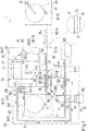
- Nachfolgend wird die Erfindung unter Bezugnahme auf eine Zeichnung näher erläutert. Hierbei zeigen:
- Fig. 1
- eine schematische Darstellung einer Vorrichtung zum Herstellen von Hologrammen im Kontaktkopierverfahren.
- In
Fig. 1 ist schematisch eine Vorrichtung 1 zum Herstellen von Hologrammen im Kontaktkopierverfahren dargestellt. Die Vorrichtung 1 umfasst eine Vielzahl von Kammern 10. In einer Zuführkammer 11 wird auf einer Vorratsrolle 25 holografisches Aufzeichnungsmaterial 20 bereitgestellt. Das holografische Aufzeichnungsmaterial 20 umfasst in der Regel eine Fotopolymerschicht 21. Zusätzlich umfasst das holografische Aufzeichnungsmaterial 20 in der Regel eine Trägerschicht 22, auf die die Fotopolymerschicht 21 aufgebracht ist. Optional kann auf der von der Trägerschicht 22 abgewandten Seite der Fotopolymerschicht 21 eine Schutzschicht 23 vorgesehen sein. Sowohl die Trägerschicht 22 als auch die Schutzschicht 23 sind transparent ausgebildet, d.h. durch sie hindurch ist eine Abbildung gemäß der geometrischen Optik möglich. Dies bedeutet ferner, dass in den Schichten keine nennenswerte Absorption und/oder diffuse Streuung stattfindet. - Das holografische Aufzeichnungsmaterial 20 wird durch eine Reaktionskammer 12, eine UV-Fixierkammer 13 sowie eine thermische Fixierkammer 14 in eine Speicherkammer 15 geführt, wo das holografische Aufzeichnungsmaterial 20, nachdem in dieses Hologramme belichtet sind, auf einer Speicherrolle 35 aufgerollt und aufgenommen wird. Der Transport des holografischen Aufzeichnungsmaterials wird von einer Transporteinrichtung 30 bewerkstelligt, die beispielsweise die Speicherrolle 35 sowie gegebenenfalls weitere Transportrollen 31 antreibt. Die Transporteinrichtung 30 zum Zu- und Abführen vom holografischen Aufzeichnungsmaterial in die Reaktionskammer 12 kann auch beliebig anders ausgebildet sein.
- Die einzelnen Kammern 10, insbesondere die Zuführkammer 11, die Reaktionskammer 12 sowie die UV-Fixierkammer 13, schützen das holografische Aufzeichnungsmaterial vor Einstrahlung von Licht von außerhalb der Vorrichtung 1. Darüber hinaus schützen sie das holografische Aufzeichnungsmaterial 20 und die darin befindlichen Einrichtungen gegenüber anderen Umwelteinflüssen, wie insbesondere Staub und Schmutz.
- In der Reaktionskammer 12 wird das holografische Aufzeichnungsmaterial 20 anliegend an einen Hologrammmaster 40 angeordnet. Vorzugsweise ist der Hologrammmaster 40 ein Master-Volumen-Reflexionshologramm 41.
- Um einen guten Kontakt zwischen dem holografischen Aufzeichnungsmaterial 20 und dem Hologrammmaster 40 zu gewährleisten, wird das holografische Aufzeichnungsmaterial 20 beispielsweise mittels eines beweglichen Rakels 50 mit einer Unterseite 27 des holografischen Aufzeichnungsmaterials 20 mit einer Oberseite 46 des Hologrammmasters 40 in Kontakt gebracht. Hierfür ist der Rakel 50 mit einer Rakelantriebs- und Führungseinrichtung 51 verbunden, die hier nur schematisch angedeutet ist.
- In einer Laserkammer 16 wird in einer kohärenten Lichtquelle 60 kohärentes Licht 81 erzeugt. In der Regel ist die kohärente Lichtquelle 60 ein Laser 61. Das kohärente Licht 81 tritt aus der Laserkammer 16 in eine Optikkammer 17 ein. Mittels einer Strahlformungs- und -führungsoptik 70 wird das kohärente Licht 81 aufgeweitet, geformt und umgelenkt und durch das holografische Aufzeichnungsmaterial 20 auf den Hologrammmaster 40 geführt. Die Strahlformungs- und -führungsoptik 70 befindet sich in einer Optikkammer 17, die oberhalb der Reaktionskammer 12 und der Laserkammer 16 ausgebildet ist. Aus der Optikkammer 17 tritt somit das zum Belichten verwendete kohärente Licht 81 der kohärenten Lichtquelle 60 in die Reaktionskammer 12 ein. Nachdem das kohärente Licht 81 das holografische Aufzeichnungsmaterial 20 passiert hat, trifft dieses auf den Hologrammmaster 40 und wird dort zumindest teilweise zurückgeworfen. Ist der Hologrammmaster 40 als Volumenreflexionshologramm ausgebildet, so wird das kohärente Licht 81 als gebeugtes Licht 82 zurückgeworfen. An anderen Hologrammmastern kann das kohärente Licht auch reflektiert werden, beispielsweise sofern der Hologrammmaster facettiert beispielsweise als Blazegitter oder Ähnliches ausgebildet ist. Das zurückgeworfene, in der Regel gebeugte Licht 82 interferiert in dem holografischen Aufzeichnungsmaterial 20 mit dem zur Belichtung eingestrahlten kohärenten Licht 81. Hierdurch werden in dem holografischen Aufzeichnungsmaterial 20 lokale Änderungen bewirkt. Ist das holografische Aufzeichnungsmaterial 20 als Fotopolymer ausgebildet, werden chemische Reaktionen ausgelöst, die zu Änderungen des Brechungsindex in der Fotopolymerschicht 21, d.h. dem holografischen Aufzeichnungsmaterial 20, führen. Die hierdurch gespeicherte Interferenzstruktur wird als Hologramm bezeichnet. Die Belichtung des Hologramms in das holografische Aufzeichnungsmaterial 20 kann zeitgleich flächig oder abtastend erfolgen, indem das kohärente Licht 81 das holografische Aufzeichnungsmaterial 20 und den darunter befindlichen Hologrammmaster 40 beispielsweise linienförmig überstreift.
- Die Strahlformungs- und -führungsoptik 70 kann optional einen räumlichen Lichtmodulator 71 umfassen, um die Intensität des zum Belichten verwendeten kohärenten Lichts 81 räumlich zu modulieren. Hierüber wird erreicht, dass beispielsweise bei einem eine homogene leuchtende Fläche, beispielsweise einer Streuscheibe, darstellenden Masterhologramm diese leuchtende Fläche lokal unterschiedlich "hell" in das Hologramm belichtet wird. Hierüber ist eine Individualisierung des Hologramms möglich.
- Der Hologrammmaster kann ausgebildet sein, ein einzelnes Hologramm oder eine Mehrzahl von Hologrammen in einem Mehrfachnutzen während eines Belichtungsvorgangs zu erzeugen. Das holografische Aufzeichnungsmaterial 20 wird bei der dargestellten Ausführungsform nicht kontinuierlich, sondern schrittweise mittels der Transporteinrichtung 30 durch die verschiedenen Kammern 10 bewegt. Nachdem in der Reaktionskammer 12 in das holografische Aufzeichnungsmaterial 20 ein Hologramm belichtet wurde, wird das holografische Aufzeichnungsmaterial 20 zunächst in die UV-Fixierkammer 13 und anschließend in die thermische Fixierkammer 14 bewegt. In der UV-Fixierkammer 13 wird das holografische Aufzeichnungsmaterial mit ultravioletter Strahlung bestrahlt. In der thermischen Fixierkammer 14 wird das holografische Aufzeichnungsmaterial erwärmt, beispielsweise über Infraroteinstrahlung. In den beiden Fixierkammern 13, 14 wird bewirkt, dass das holografische Aufzeichnungsmaterial seine Fotoempfindlichkeit verliert und zugleich das Hologramm permanent in dem holografischen Aufzeichnungsmaterial 20 in Form der Brechungsindexänderungen gespeichert wird. Bei anderen holografischen Aufzeichnungsmaterialien können andere Nachbearbeitungsschritte zum Entwickeln und/oder Fixieren des Hologramms notwendig und vorgesehen sein.
- Es hat sich herausgestellt, dass eine erreichbare Beugungseffizienz in den auf diese Weise kopierten Hologrammen gesteigert werden kann, wenn die Reaktionskammer 12 gekühlt wird. Hierfür ist eine Kühlvorrichtung 100 vorgesehen. In
Fig. 1 ist eine Kühlvorrichtung 100 schematisch dargestellt, die unterschiedliche Kühleinrichtungen und/oder Kühlvarianten vereinigt. Es versteht sich für den Fachmann, dass andere Ausführungsformen nur eine und gegebenenfalls alternativ ausgebildete Kühlvariante umfassen können. - Eine Kühlvariante besteht darin, dass ein Kühlfluid 300 in die Reaktionskammer eingeströmt wird. Vorzugsweise ist das Kühlfluid 300 ein abgekühltes Gas oder Gasgemisch. Besonders bevorzugt ist dieses wasserfrei. Das Fluid 300 wird vorzugsweise mittels einer Fluideinströmeinrichtung 110 in die Reaktionskammer 12 eingeströmt. Die Fluideinströmeinrichtung 110 umfasst beispielsweise ein oder mehrere Zuführgebläse 111, die das Kühlfluid 300 zu einer Einströmöffnung 112 fördern. Nachdem das Kühlfluid 300 in der Reaktionskammer 12 erwärmt ist, strömt dieses vorzugsweise in einem oberen Bereich der Reaktionskammer aus einer oder mehreren Ausströmöffnungen 113 aus. Das Kühlfluid 300 kann einer Umgebung der Vorrichtung 1 entnommen oder aus einem Vorratsspeicher 310 beispielsweise einer Druckgasflasche stammen. Insbesondere wenn das Kühlfluid 300 aus der Umgebung entnommen wird, kann die Kühlvorrichtung eine Reinigungs- und Filtereinheit 116 umfassen. Vorzugsweise kann zusätzlich eine Trocknungseinheit 117 vorgesehen sein, mittels der in dem aus der Umgebung aufgenommenen Fluid enthaltenes Wasser entzogen und/oder auskondensiert wird. Das Kühlfluid 300 wird vorzugsweise an einer Wärmetauschereinheit 115 vorbeigeführt und gegenüber einer Umgebung abgekühlt. Das Kühlfluid 300 wird vorzugsweise auf Höhe des Hologrammmasters 40 und/oder des holografischen Aufzeichnungsmaterials 20 in die Reaktionskammer 12 eingeströmt, sodass das holografische Aufzeichnungsmaterial 20 und der Hologrammmaster 40 gekühlt werden.
- Die Wärmetauschereinheit 115 wird vorzugsweise von einem sekundären Kühlfluid 400 durchströmt und nimmt die von dem Kühlfluid 300 abgegebene Wärme auf und führt diese an eine Energiesenke 500 ab. Dieses kann eine Kältemaschine oder auch ein Kühlwasserkreislauf sein.
- Die dargestellte Ausführungsform der Kühlvorrichtung 100 weist als weitere Kühlvariante ein Kühlregister 120 auf, welches direkt oder über eine Wärmeleiterplatte mit dem Hologrammmaster 40 wärmeleitend verbunden ist. Das Kühlregister 120 wird vorzugsweise von dem sekundären Kühlfluid 400 durchströmt, welches die vom Hologrammmaster aufgenommene Wärmeenergie an die Energiesenke 500 abgibt.
- In der dargestellten Ausführungsform umfasst die Kühlvorrichtung 100 zusätzlich als Kühlvariante ein Wärmerohr 130. Im Innern des Wärmerohrs befindet sich ein Arbeitsmedium, welches sich in einem unteren Bereich 137 des Wärmerohrs als Flüssigkeit sammelt. Über die Außenwand des Wärmerohrs, welches in die Reaktionskammer 12 hineinragt, wird Wärme aufgenommen und so das Innere der Reaktionskammer 12 gekühlt. Die Wärme bewirkt einen Phasenübergang in dem Arbeitsmedium, sodass dieses gasförmig wird und in dem Wärmerohr in den oberen Bereich 136 gelangt. Dort wird über die Außenwand des Wärmerohrs Wärmeenergie abgegeben, sodass erneut ein Phasenübergang im Arbeitsmedium stattfindet und dieses im flüssigen Aggregatzustand erneut schwerkraftgetrieben oder aufgrund von Kapillarkräften in den unteren Bereich 137 des Wärmerohrs 130 gelangt. Die Wärme im oberen Bereich 136 des Wärmerohrs 130 kann beispielsweise mittels eines Kühlgebläses 140 der Kühlvorrichtung 100 an die Umgebungsluft abgeführt werden. Alternativ oder zusätzlich kann das Wärmerohr 130 im oberen Bereich durch eine Kühlleitung 150 gekühlt werden, welche von dem sekundären Kühlfluid 400 durchströmt wird.
- Es versteht sich für den Fachmann, dass die verschiedenen Varianten, mit denen die dargestellte Kühlvorrichtung 100 ausgebildet ist, in beliebiger Kombination verwendet werden können, um die Reaktionskammer 12 zu kühlen. Insbesondere können mehrere Einströmeinrichtung 110 und/oder mehrere Wärmerohre 130 und/oder mehrere Kühlregister 120 vorgesehen sein. Ferner können mehrere Kühlkreisläufe für sekundäres Kühlfluid vorgesehen sein. Die Kühlvorrichtung kann darüber hinaus mehrere Kältemaschinen als Energiesenken und/oder zusätzlich oder alternativ Kühlwasserkreisläufe besitzen.
- Abweichend von der dargestellten Ausführungsform, bei der das Kühlregister 120 von dem sekundären Kühlfluid 400 unmittelbar durchströmt wird, kann das Kühlregister 120 einen geschlossenen primären Kühlfluidkreislauf umfassen (gestrichelt dargestellt), der über eine weitere Wärmetauschereinheit 125 seine Wärme an das sekundäre Kühlfluid 400 abgibt, welches mit einer Energiesenke 500 in Form einer Kältemaschine und/oder einer Kühlwasserleitung oder Ähnlichem gekoppelt ist. Das sekundäre Kühlfluid 400 kann unmittelbar mit einer Kühlwasserleitung verbunden sein, sodass das Kühlwasser das sekundäre Kühlfluid 400 ist. In der Regel wird jedoch das sekundäre Kühlfluid 400 in einem geschlossenen Kühlkreislauf zirkulieren und in der Kältemaschine abgekühlt bzw. von Kühlwasser über einen Wärmetauscher abgekühlt, in dem das sekundäre Kühlfluid 400 seine Energie abgibt.
- Abweichend von der dargestellten Ausführungsform können statt des Wärmerohrs 130 auch im oberen Bereich der Reaktionskammer ein oder mehrere direkt von dem sekundären Kühlfluid 400 durchströmte Kühlregister vorgesehen sein.
-
- 1
- Vorrichtung zum Herstellen von Hologrammen
- 10
- Kammern
- 11
- Zuführkammer
- 12
- Reaktionskammer
- 13
- UV-Fixierkammer
- 14
- thermische Fixierkammer
- 15
- Speicherkammer
- 16
- Laserkammer
- 17
- Optikammer
- 20
- holographisches Aufzeichnungsmaterial
- 21
- Fotopolymer
- 25
- Vorratsrolle
- 26
- Oberseite
- 27
- Unterseite
- 30
- Transporteinrichtung
- 35
- Speicherrolle
- 40
- Hologrammmaster
- 41
- Master-Volumen-Reflexionshologramm
- 46
- Oberseite
- 50
- Rakel
- 51
- Rakelantriebs- und Führungseinrichtung
- 60
- kohärente Lichtquelle
- 61
- Laser
- 70
- Strahlformungs- und -führungsoptik
- 71
- räumlicher Lichtmodulator (spatial light modulator)
- 81
- kohärentes Licht
- 82
- gebeugtes/reflektiertes Licht
- 90
- UV - Strahler
- 91
- UV - Strahlung
- 95
- Infrarot - Strahler
- 100
- Kühlvorrichtung
- 110
- Fluideinströmeinrichtung
- 111
- Zuführgebläse
- 112
- Einströmöffnung
- 113
- Ausströmöffnung
- 115
- Wärmetauschereinheit
- 116
- Reinigungs- und Filtereinheit
- 117
- Trocknungseinheit
- 120
- Kühlregister
- 121
- Wärmeleitplatte
- 125
- weitere Wärmetauschereinheit
- 130
- Wärmerohr
- 136
- oberer Bereich
- 137
- unterer Bereich
- 140
- Kühlgebläse
- 150
- Kühlleitung
- 151
- Zuführleitung
- 152
- Abführleitung
- 300
- Kühlfluid
- 310
- Vorratsspeicher
- 400
- sekundäres Kühlfluid
- 500
- Energiesenke
(e) mittels einer Kühlvorrichtung Wärme aus der Reaktionskammer abgeführt wird.
Claims (11)
- Vorrichtung (1) zum Herstellen von Hologrammen im Kontaktkopierverfahren umfassendeinen Hologrammmaster (40),eine kohärente Lichtquelle (60) zum Erzeugen kohärenten Lichts (81),eine Transporteinrichtung (30) zum Zu- und Abführen von holografischem Aufzeichnungsmaterial (20), so dass dieses für einen Belichtungsvorgang anliegend an dem Hologrammmaster (40) angeordnet wird, undeine Reaktionskammer (12), die den Hologrammmaster (40) umgibt und das holografische Aufzeichnungsmaterial (20) während des Belichtungsvorgangs vor Umgebungslicht und Fremdmaterial schützt, wobei das kohärente Licht (81) der kohärenten Lichtquelle (60) während des Belichtungsvorgangs in die Reaktionskammer (12) eingestrahlt wird, so dass das kohärente Licht (81) das anliegend an und vor dem Hologrammmaster (40) angeordnete holografische Aufzeichnungsmaterial durchstrahlt und zumindest teilweise an dem Hologrammmaster (40) zurückgestrahlt wird, so dass im Innern des holografischen Aufzeichnungsmaterials (20) aufgrund von Interferenzen zwischen dem das holografische Aufzeichnungsmaterial (20) durchstrahlenden kohärenten Licht (81) und dem zumindest teilweise vom Hologrammmaster (40) zurückgestrahlten Licht (82) Änderungen herbeigeführt werden, die ein Hologramm ausbilden, oder so dass der Hologrammmaster (40) durchstrahlt wird, so dass ein Anteil des kohärenten Lichts (81) den Hologrammmaster (40) unverändert passiert und ein weiterer Anteil des kohärenten Lichts an dem Holgrammmaster (40) abgelenkt wird, so dass aufgrund von Interferenzen zwischen dem einen unveränderte Anteil (81) des kohärenten Lichts und dem weiteren abgelenkten Anteil des kohärenten Lichts (82) im Innern des anliegend an und hinter dem Holgrammmaster (40) angeordneten holografischen Aufzeichnungsmaterial (20) Änderungen herbeigeführt werden, die das Hologramm ausbilden,dadurch gekennzeichnet, dasseine Kühlvorrichtung (100) zum Abführen von Wärme aus der Reaktionskammer (12) ausgebildet ist.
- Vorrichtung (1) nach Anspruch 1, dadurch gekennzeichnet, dass die Kühlvorrichtung (100) ein Kühlfluid in die Reaktionskammer (12) einströmt.
- Vorrichtung (1) nach Anspruch 1 oder 2, dadurch gekennzeichnet, dass die Kühlvorrichtung (100) mindestens ein Wärmerohr (130) umfasst.
- Vorrichtung (1) nach einem der vorangehenden Ansprüche, dadurch gekennzeichnet, dass mit dem Hologrammmaster (40) mindestens ein Element der Kühlvorrichtung (100) wärmeleitend verbunden ist, um den Hologrammmaster (40) zu kühlen.
- Vorrichtung (1) nach einem der vorangehenden Ansprüche, dadurch gekennzeichnet, dass mindestens ein Bauteil der Reaktionskammer wärmeleitend in Kontakt mit dem mindestens einen Wärmerohr und/oder einem weiteren Element der Kühlvorrichtung angeordnet sind, um die Reaktionskammer zu kühlen.
- Vorrichtung (1) nach einem der vorangehenden Ansprüche, dadurch gekennzeichnet, dass die Kühlvorrichtung (100) Wärme an eine Energiesenke (500) abgibt.
- Vorrichtung (1) nach Anspruch 6, dadurch gekennzeichnet, dass die Energiesenke (500) eine sekundäre Fluidströmung und/oder eine Kältemaschine umfasst.
- Verfahren zum Herstellen von Hologrammen im Kontaktkopierprozess umfassend(a) Bereitstellen eines Hologrammmasters (40) in einer Reaktionskammer (12), die den Hologrammmaster (40) umgibt und vor Umgebungslicht und Fremdmaterial schützt,(b) Zuführen von holografischem Aufzeichnungsmaterial (20) in eine Reaktionskammer (12), die den Hologrammmaster (40) umgibt, so dass das holografische Aufzeichnungsmaterial (20) für einen Belichtungsvorgang anliegend an dem Hologrammmaster (40) angeordnet wird,(c) Ausführen eines Belichtungsvorgangs, indem kohärentes Licht erzeugt und in die Reaktionskammer (12) eingestrahlt wird, so dass das kohärente Licht das anliegend an und vor dem Hologrammmaster (40) angeordnete holografische Aufzeichnungsmaterial (20) durchstrahlt und zumindest teilweise an dem Master zurückgestrahlt wird, so dass im Innern des holografischen Aufzeichnungsmaterials (20) aufgrund von Interferenzen zwischen dem das holografische Aufzeichnungsmaterial durchstrahlenden kohärenten Licht und dem zumindest teilweise vom Hologrammmaster (40) zurückgestrahlten Licht Änderungen herbeigeführt werden, die ein Hologramm ausbilden, oder so dass der Hologrammmaster (40) durchstrahlt wird und ein Anteil des kohärenten Lichts (81) den Hologrammmaster (40) unverändert passiert und ein weiterer Anteil des kohärenten Lichts (82) an dem Hologrammmaster (40) abgelenkt wird, so dass aufgrund von Interferenzen zwischen dem einen unteränderte Anteil des kohärenten Lichts (81) und dem weiteren abgelenkten Anteil des kohärenten Lichts (82) im Innern des anliegend an und hinter dem Holgrammmaster (40) angeordneten holografischen Aufzeichnungsmaterial (20) Änderungen herbeigeführt werden, die das Hologramm ausbilden,(d) Abführen des holografischen Aufzeichnungsmaterials (20) aus der Reaktionskammer (12),dadurch gekennzeichnet, dass
(e) mittels eiern Kühlvorrichtung (100) Wärme aus der Reaktionskammer (12) abgeführt wird. - Verfahren nach Anspruch 8, dadurch gekennzeichnet, dass die Verfahrensschritte (b) bis (d) iterativ ausgeführt werden, während der Verfahrensschritt (e) ausgeführt wird.
- Verfahren nach Anspruch 8 oder 9, dadurch gekennzeichnet, dass die Wärme mittels einer Kühlvorrichtung (100) aus der Reaktionskammer (12) abgeführt wird, die wiederum Wärme an eine Energiesenke (500) abgibt.
- Verfahren nach einem der Ansprüche 8 bis 10, dadurch gekennzeichnet, dass die Wärme aus der Reaktionskammer (12) mittels eines Wärmerohrs (130) der Kühlvorrichtung (100) abgeführt wird.
Applications Claiming Priority (1)
| Application Number | Priority Date | Filing Date | Title |
|---|---|---|---|
| DE102021206107.9A DE102021206107B4 (de) | 2021-06-15 | 2021-06-15 | Vorrichtung und Verfahren zum Herstellen von Hologrammen im Kontaktkopierverfahren mit hoher Beugungseffizienz |
Publications (2)
| Publication Number | Publication Date |
|---|---|
| EP4105730A1 true EP4105730A1 (de) | 2022-12-21 |
| EP4105730B1 EP4105730B1 (de) | 2024-12-18 |
Family
ID=82067609
Family Applications (1)
| Application Number | Title | Priority Date | Filing Date |
|---|---|---|---|
| EP22179192.4A Active EP4105730B1 (de) | 2021-06-15 | 2022-06-15 | Vorrichtung zum herstellen von hologrammen im kontaktkopieverfahren mit hoher beugungseffizienz |
Country Status (2)
| Country | Link |
|---|---|
| EP (1) | EP4105730B1 (de) |
| DE (1) | DE102021206107B4 (de) |
Citations (3)
| Publication number | Priority date | Publication date | Assignee | Title |
|---|---|---|---|---|
| US20030179424A1 (en) * | 2001-06-27 | 2003-09-25 | Nobuhiro Kihara | Image exposure recorder and image exposure recording method |
| JP2007041360A (ja) * | 2005-08-04 | 2007-02-15 | Sony Corp | ホログラム装置及び記録媒体温度制御方法 |
| DE112006002839B4 (de) * | 2005-10-28 | 2012-04-26 | Toyota Jidosha Kabushiki Kaisha | Anordnung aus einer elektrischen Vorrichtung und einer Kühlstruktur für die elektrische Vorrichtung |
Family Cites Families (3)
| Publication number | Priority date | Publication date | Assignee | Title |
|---|---|---|---|---|
| US5297005A (en) | 1992-09-28 | 1994-03-22 | Energy Innovations, Inc. | Apparatus and method for cooling heat generating electronic components in a cabinet |
| GB2457727A (en) | 2008-02-25 | 2009-08-26 | Valor Ltd | Process for producing holograms |
| JP6609643B2 (ja) | 2016-01-26 | 2019-11-20 | 富士フイルム株式会社 | レーザ装置 |
-
2021
- 2021-06-15 DE DE102021206107.9A patent/DE102021206107B4/de active Active
-
2022
- 2022-06-15 EP EP22179192.4A patent/EP4105730B1/de active Active
Patent Citations (3)
| Publication number | Priority date | Publication date | Assignee | Title |
|---|---|---|---|---|
| US20030179424A1 (en) * | 2001-06-27 | 2003-09-25 | Nobuhiro Kihara | Image exposure recorder and image exposure recording method |
| JP2007041360A (ja) * | 2005-08-04 | 2007-02-15 | Sony Corp | ホログラム装置及び記録媒体温度制御方法 |
| DE112006002839B4 (de) * | 2005-10-28 | 2012-04-26 | Toyota Jidosha Kabushiki Kaisha | Anordnung aus einer elektrischen Vorrichtung und einer Kühlstruktur für die elektrische Vorrichtung |
Also Published As
| Publication number | Publication date |
|---|---|
| DE102021206107B4 (de) | 2024-09-12 |
| EP4105730B1 (de) | 2024-12-18 |
| DE102021206107A1 (de) | 2022-12-15 |
Similar Documents
| Publication | Publication Date | Title |
|---|---|---|
| EP2467247B1 (de) | Verfahren und vorrichtung zur herstellung eines dreidimensionalen objektes | |
| DE102012008216B4 (de) | Verdunstungs-wärmemanagement von kollektoren mit streifendem einfall für die euv-lithographie | |
| DE60303882T2 (de) | Kontaminationsschutz mit ausdehnbaren Lamellen | |
| US20080186579A1 (en) | System and a Method for Generating Periodic and/or Quasi-Periodic Pattern on a Sample | |
| DE112016001162T5 (de) | Apparat und Verfahren zur indirekten Oberflächenreinigung | |
| DE102010002298A1 (de) | Projektionsbelichtungsanlage für die Halbleiterlithographie mit einer Kühlvorrichtung | |
| DE2538875A1 (de) | Einrichtung zum speichern und auslesen von echtheitsinformationen | |
| DE4117839C2 (de) | Strahlentesteinrichtungen und Verfahren für die Röntgenstrahl-Lithografie | |
| DE1963578A1 (de) | Verfahren zum kontaktlosen Belichten | |
| DE102009035788A1 (de) | Optische Anordnung in einem optischen System, insbesondere einer Beleuchtungseinrichtung | |
| DE102011086513A1 (de) | Projektionsbelichtungsverfahren und Projektionsbelichtungsanlage für die Mikrolithographie | |
| DE102019124919A1 (de) | Mikroskopisches System zur Prüfung von Strukturen und Defekten auf EUV-Lithographie-Photomasken | |
| DE69531196T2 (de) | Vorrichtung und verfahren zur herstellung von transmissionshologrammen | |
| Cheng et al. | Laser activation of single group-IV colour centres in diamond | |
| DE2101871A1 (de) | Holographisches Abbildungsverfahren | |
| EP4105730B1 (de) | Vorrichtung zum herstellen von hologrammen im kontaktkopieverfahren mit hoher beugungseffizienz | |
| DE68922945T2 (de) | Belichtungsvorrichtung. | |
| Huang et al. | Demonstration of full-scale spatiotemporal diagnostics of solid-density plasmas driven by an ultra-short relativistic laser pulse using an X-ray free-electron laser | |
| DE102010039965A1 (de) | EUV-Kollektor | |
| DE10106888B4 (de) | Verfahren und Vorrichtung zur Herstellung einer Oberflächenbeschichtung | |
| EP2895921B1 (de) | Verfahren zur herstellung eines volumenreflexions-hologramms mit verbesserter marker-ausbildung | |
| DE1547872A1 (de) | Verfahren zur Aufzeichnung eines radiographischen Bildes | |
| DE102015201253A1 (de) | Thermisch optimierte obskurationsblenden und projektionsbelichtungsanlage mit derartigen blenden | |
| DE102022202241A1 (de) | Optisches system und projektionsbelichtungsanlage | |
| Nakajima et al. | Gas-permeable templates using cellulose derivatives with acrylate and methacrylate groups for reducing in void defect density in ultraviolet nanoimprint lithography |
Legal Events
| Date | Code | Title | Description |
|---|---|---|---|
| PUAI | Public reference made under article 153(3) epc to a published international application that has entered the european phase |
Free format text: ORIGINAL CODE: 0009012 |
|
| STAA | Information on the status of an ep patent application or granted ep patent |
Free format text: STATUS: THE APPLICATION HAS BEEN PUBLISHED |
|
| AK | Designated contracting states |
Kind code of ref document: A1 Designated state(s): AL AT BE BG CH CY CZ DE DK EE ES FI FR GB GR HR HU IE IS IT LI LT LU LV MC MK MT NL NO PL PT RO RS SE SI SK SM TR |
|
| STAA | Information on the status of an ep patent application or granted ep patent |
Free format text: STATUS: REQUEST FOR EXAMINATION WAS MADE |
|
| P01 | Opt-out of the competence of the unified patent court (upc) registered |
Effective date: 20230526 |
|
| 17P | Request for examination filed |
Effective date: 20230620 |
|
| RBV | Designated contracting states (corrected) |
Designated state(s): AL AT BE BG CH CY CZ DE DK EE ES FI FR GB GR HR HU IE IS IT LI LT LU LV MC MK MT NL NO PL PT RO RS SE SI SK SM TR |
|
| GRAP | Despatch of communication of intention to grant a patent |
Free format text: ORIGINAL CODE: EPIDOSNIGR1 |
|
| STAA | Information on the status of an ep patent application or granted ep patent |
Free format text: STATUS: GRANT OF PATENT IS INTENDED |
|
| RIC1 | Information provided on ipc code assigned before grant |
Ipc: G11B 7/26 20060101ALN20240725BHEP Ipc: G03H 1/20 20060101ALN20240725BHEP Ipc: B65H 20/00 20060101ALN20240725BHEP Ipc: G03H 1/04 20060101ALN20240725BHEP Ipc: G03H 1/00 20060101ALN20240725BHEP Ipc: B32B 37/08 20060101ALN20240725BHEP Ipc: G03H 1/02 20060101AFI20240725BHEP |
|
| INTG | Intention to grant announced |
Effective date: 20240805 |
|
| RIC1 | Information provided on ipc code assigned before grant |
Ipc: G11B 7/26 20060101ALN20240729BHEP Ipc: G03H 1/20 20060101ALN20240729BHEP Ipc: B65H 20/00 20060101ALN20240729BHEP Ipc: G03H 1/04 20060101ALN20240729BHEP Ipc: G03H 1/00 20060101ALN20240729BHEP Ipc: B32B 37/08 20060101ALN20240729BHEP Ipc: G03H 1/02 20060101AFI20240729BHEP |
|
| GRAS | Grant fee paid |
Free format text: ORIGINAL CODE: EPIDOSNIGR3 |
|
| GRAA | (expected) grant |
Free format text: ORIGINAL CODE: 0009210 |
|
| STAA | Information on the status of an ep patent application or granted ep patent |
Free format text: STATUS: THE PATENT HAS BEEN GRANTED |
|
| AK | Designated contracting states |
Kind code of ref document: B1 Designated state(s): AL AT BE BG CH CY CZ DE DK EE ES FI FR GB GR HR HU IE IS IT LI LT LU LV MC MK MT NL NO PL PT RO RS SE SI SK SM TR |
|
| REG | Reference to a national code |
Ref country code: CH Ref legal event code: EP |
|
| REG | Reference to a national code |
Ref country code: DE Ref legal event code: R096 Ref document number: 502022002416 Country of ref document: DE |
|
| REG | Reference to a national code |
Ref country code: IE Ref legal event code: FG4D Free format text: LANGUAGE OF EP DOCUMENT: GERMAN |
|
| REG | Reference to a national code |
Ref country code: LT Ref legal event code: MG9D |
|
| PG25 | Lapsed in a contracting state [announced via postgrant information from national office to epo] |
Ref country code: HR Free format text: LAPSE BECAUSE OF FAILURE TO SUBMIT A TRANSLATION OF THE DESCRIPTION OR TO PAY THE FEE WITHIN THE PRESCRIBED TIME-LIMIT Effective date: 20241218 |
|
| PG25 | Lapsed in a contracting state [announced via postgrant information from national office to epo] |
Ref country code: FI Free format text: LAPSE BECAUSE OF FAILURE TO SUBMIT A TRANSLATION OF THE DESCRIPTION OR TO PAY THE FEE WITHIN THE PRESCRIBED TIME-LIMIT Effective date: 20241218 |
|
| PG25 | Lapsed in a contracting state [announced via postgrant information from national office to epo] |
Ref country code: BG Free format text: LAPSE BECAUSE OF FAILURE TO SUBMIT A TRANSLATION OF THE DESCRIPTION OR TO PAY THE FEE WITHIN THE PRESCRIBED TIME-LIMIT Effective date: 20241218 |
|
| PG25 | Lapsed in a contracting state [announced via postgrant information from national office to epo] |
Ref country code: NO Free format text: LAPSE BECAUSE OF FAILURE TO SUBMIT A TRANSLATION OF THE DESCRIPTION OR TO PAY THE FEE WITHIN THE PRESCRIBED TIME-LIMIT Effective date: 20250318 |
|
| REG | Reference to a national code |
Ref country code: NL Ref legal event code: MP Effective date: 20241218 |
|
| PG25 | Lapsed in a contracting state [announced via postgrant information from national office to epo] |
Ref country code: LV Free format text: LAPSE BECAUSE OF FAILURE TO SUBMIT A TRANSLATION OF THE DESCRIPTION OR TO PAY THE FEE WITHIN THE PRESCRIBED TIME-LIMIT Effective date: 20241218 Ref country code: GR Free format text: LAPSE BECAUSE OF FAILURE TO SUBMIT A TRANSLATION OF THE DESCRIPTION OR TO PAY THE FEE WITHIN THE PRESCRIBED TIME-LIMIT Effective date: 20250319 |
|
| PG25 | Lapsed in a contracting state [announced via postgrant information from national office to epo] |
Ref country code: RS Free format text: LAPSE BECAUSE OF FAILURE TO SUBMIT A TRANSLATION OF THE DESCRIPTION OR TO PAY THE FEE WITHIN THE PRESCRIBED TIME-LIMIT Effective date: 20250318 |
|
| PG25 | Lapsed in a contracting state [announced via postgrant information from national office to epo] |
Ref country code: NL Free format text: LAPSE BECAUSE OF FAILURE TO SUBMIT A TRANSLATION OF THE DESCRIPTION OR TO PAY THE FEE WITHIN THE PRESCRIBED TIME-LIMIT Effective date: 20241218 |
|
| PG25 | Lapsed in a contracting state [announced via postgrant information from national office to epo] |
Ref country code: SM Free format text: LAPSE BECAUSE OF FAILURE TO SUBMIT A TRANSLATION OF THE DESCRIPTION OR TO PAY THE FEE WITHIN THE PRESCRIBED TIME-LIMIT Effective date: 20241218 |
|
| PG25 | Lapsed in a contracting state [announced via postgrant information from national office to epo] |
Ref country code: PL Free format text: LAPSE BECAUSE OF FAILURE TO SUBMIT A TRANSLATION OF THE DESCRIPTION OR TO PAY THE FEE WITHIN THE PRESCRIBED TIME-LIMIT Effective date: 20241218 |
|
| PGFP | Annual fee paid to national office [announced via postgrant information from national office to epo] |
Ref country code: DE Payment date: 20250618 Year of fee payment: 4 |
|
| PG25 | Lapsed in a contracting state [announced via postgrant information from national office to epo] |
Ref country code: ES Free format text: LAPSE BECAUSE OF FAILURE TO SUBMIT A TRANSLATION OF THE DESCRIPTION OR TO PAY THE FEE WITHIN THE PRESCRIBED TIME-LIMIT Effective date: 20241218 |
|
| PG25 | Lapsed in a contracting state [announced via postgrant information from national office to epo] |
Ref country code: IS Free format text: LAPSE BECAUSE OF FAILURE TO SUBMIT A TRANSLATION OF THE DESCRIPTION OR TO PAY THE FEE WITHIN THE PRESCRIBED TIME-LIMIT Effective date: 20250418 |
|
| PG25 | Lapsed in a contracting state [announced via postgrant information from national office to epo] |
Ref country code: PT Free format text: LAPSE BECAUSE OF FAILURE TO SUBMIT A TRANSLATION OF THE DESCRIPTION OR TO PAY THE FEE WITHIN THE PRESCRIBED TIME-LIMIT Effective date: 20250421 |
|
| PG25 | Lapsed in a contracting state [announced via postgrant information from national office to epo] |
Ref country code: EE Free format text: LAPSE BECAUSE OF FAILURE TO SUBMIT A TRANSLATION OF THE DESCRIPTION OR TO PAY THE FEE WITHIN THE PRESCRIBED TIME-LIMIT Effective date: 20241218 |
|
| PGFP | Annual fee paid to national office [announced via postgrant information from national office to epo] |
Ref country code: FR Payment date: 20250626 Year of fee payment: 4 |
|
| PG25 | Lapsed in a contracting state [announced via postgrant information from national office to epo] |
Ref country code: RO Free format text: LAPSE BECAUSE OF FAILURE TO SUBMIT A TRANSLATION OF THE DESCRIPTION OR TO PAY THE FEE WITHIN THE PRESCRIBED TIME-LIMIT Effective date: 20241218 |
|
| PGFP | Annual fee paid to national office [announced via postgrant information from national office to epo] |
Ref country code: AT Payment date: 20250721 Year of fee payment: 4 |
|
| PG25 | Lapsed in a contracting state [announced via postgrant information from national office to epo] |
Ref country code: SK Free format text: LAPSE BECAUSE OF FAILURE TO SUBMIT A TRANSLATION OF THE DESCRIPTION OR TO PAY THE FEE WITHIN THE PRESCRIBED TIME-LIMIT Effective date: 20241218 |
|
| PG25 | Lapsed in a contracting state [announced via postgrant information from national office to epo] |
Ref country code: CZ Free format text: LAPSE BECAUSE OF FAILURE TO SUBMIT A TRANSLATION OF THE DESCRIPTION OR TO PAY THE FEE WITHIN THE PRESCRIBED TIME-LIMIT Effective date: 20241218 |
|
| PG25 | Lapsed in a contracting state [announced via postgrant information from national office to epo] |
Ref country code: IT Free format text: LAPSE BECAUSE OF FAILURE TO SUBMIT A TRANSLATION OF THE DESCRIPTION OR TO PAY THE FEE WITHIN THE PRESCRIBED TIME-LIMIT Effective date: 20241218 |
|
| PG25 | Lapsed in a contracting state [announced via postgrant information from national office to epo] |
Ref country code: SE Free format text: LAPSE BECAUSE OF FAILURE TO SUBMIT A TRANSLATION OF THE DESCRIPTION OR TO PAY THE FEE WITHIN THE PRESCRIBED TIME-LIMIT Effective date: 20241218 |
|
| REG | Reference to a national code |
Ref country code: DE Ref legal event code: R097 Ref document number: 502022002416 Country of ref document: DE |
|
| PG25 | Lapsed in a contracting state [announced via postgrant information from national office to epo] |
Ref country code: DK Free format text: LAPSE BECAUSE OF FAILURE TO SUBMIT A TRANSLATION OF THE DESCRIPTION OR TO PAY THE FEE WITHIN THE PRESCRIBED TIME-LIMIT Effective date: 20241218 |
|
| REG | Reference to a national code |
Ref country code: CH Ref legal event code: W10 Free format text: ST27 STATUS EVENT CODE: U-0-0-W10-W00 (AS PROVIDED BY THE NATIONAL OFFICE) Effective date: 20251015 |
|
| PLBE | No opposition filed within time limit |
Free format text: ORIGINAL CODE: 0009261 |
|
| STAA | Information on the status of an ep patent application or granted ep patent |
Free format text: STATUS: NO OPPOSITION FILED WITHIN TIME LIMIT |
|
| REG | Reference to a national code |
Ref country code: CH Ref legal event code: L10 Free format text: ST27 STATUS EVENT CODE: U-0-0-L10-L00 (AS PROVIDED BY THE NATIONAL OFFICE) Effective date: 20251029 |
|
| RAP4 | Party data changed (patent owner data changed or rights of a patent transferred) |
Owner name: BUNDESDRUCKEREI GMBH |
|
| 26N | No opposition filed |
Effective date: 20250919 |
|
| REG | Reference to a national code |
Ref country code: CH Ref legal event code: H13 Free format text: ST27 STATUS EVENT CODE: U-0-0-H10-H13 (AS PROVIDED BY THE NATIONAL OFFICE) Effective date: 20260127 |
|
| PG25 | Lapsed in a contracting state [announced via postgrant information from national office to epo] |
Ref country code: MC Free format text: LAPSE BECAUSE OF FAILURE TO SUBMIT A TRANSLATION OF THE DESCRIPTION OR TO PAY THE FEE WITHIN THE PRESCRIBED TIME-LIMIT Effective date: 20241218 |
|
| PG25 | Lapsed in a contracting state [announced via postgrant information from national office to epo] |
Ref country code: LU Free format text: LAPSE BECAUSE OF NON-PAYMENT OF DUE FEES Effective date: 20250615 |
|
| REG | Reference to a national code |
Ref country code: BE Ref legal event code: MM Effective date: 20250630 |
|
| PG25 | Lapsed in a contracting state [announced via postgrant information from national office to epo] |
Ref country code: IE Free format text: LAPSE BECAUSE OF NON-PAYMENT OF DUE FEES Effective date: 20250615 |
|
| PG25 | Lapsed in a contracting state [announced via postgrant information from national office to epo] |
Ref country code: BE Free format text: LAPSE BECAUSE OF NON-PAYMENT OF DUE FEES Effective date: 20250630 |
|
| PG25 | Lapsed in a contracting state [announced via postgrant information from national office to epo] |
Ref country code: CH Free format text: LAPSE BECAUSE OF NON-PAYMENT OF DUE FEES Effective date: 20250630 |