EP4105576A1 - Economizer for refrigeration system and refrigeration system - Google Patents
Economizer for refrigeration system and refrigeration system Download PDFInfo
- Publication number
- EP4105576A1 EP4105576A1 EP22179463.9A EP22179463A EP4105576A1 EP 4105576 A1 EP4105576 A1 EP 4105576A1 EP 22179463 A EP22179463 A EP 22179463A EP 4105576 A1 EP4105576 A1 EP 4105576A1
- Authority
- EP
- European Patent Office
- Prior art keywords
- economizer
- refrigeration system
- liquid
- gas
- pipe
- Prior art date
- Legal status (The legal status is an assumption and is not a legal conclusion. Google has not performed a legal analysis and makes no representation as to the accuracy of the status listed.)
- Granted
Links
Images
Classifications
-
- F—MECHANICAL ENGINEERING; LIGHTING; HEATING; WEAPONS; BLASTING
- F25—REFRIGERATION OR COOLING; COMBINED HEATING AND REFRIGERATION SYSTEMS; HEAT PUMP SYSTEMS; MANUFACTURE OR STORAGE OF ICE; LIQUEFACTION SOLIDIFICATION OF GASES
- F25B—REFRIGERATION MACHINES, PLANTS OR SYSTEMS; COMBINED HEATING AND REFRIGERATION SYSTEMS; HEAT PUMP SYSTEMS
- F25B43/00—Arrangements for separating or purifying gases or liquids; Arrangements for vaporising the residuum of liquid refrigerant, e.g. by heat
-
- F—MECHANICAL ENGINEERING; LIGHTING; HEATING; WEAPONS; BLASTING
- F25—REFRIGERATION OR COOLING; COMBINED HEATING AND REFRIGERATION SYSTEMS; HEAT PUMP SYSTEMS; MANUFACTURE OR STORAGE OF ICE; LIQUEFACTION SOLIDIFICATION OF GASES
- F25B—REFRIGERATION MACHINES, PLANTS OR SYSTEMS; COMBINED HEATING AND REFRIGERATION SYSTEMS; HEAT PUMP SYSTEMS
- F25B31/00—Compressor arrangements
-
- F—MECHANICAL ENGINEERING; LIGHTING; HEATING; WEAPONS; BLASTING
- F25—REFRIGERATION OR COOLING; COMBINED HEATING AND REFRIGERATION SYSTEMS; HEAT PUMP SYSTEMS; MANUFACTURE OR STORAGE OF ICE; LIQUEFACTION SOLIDIFICATION OF GASES
- F25B—REFRIGERATION MACHINES, PLANTS OR SYSTEMS; COMBINED HEATING AND REFRIGERATION SYSTEMS; HEAT PUMP SYSTEMS
- F25B2400/00—Component parts or details not otherwise provided for in this subclass
- F25B2400/02—Centrifugal separation of gas, liquid or oil
-
- F—MECHANICAL ENGINEERING; LIGHTING; HEATING; WEAPONS; BLASTING
- F25—REFRIGERATION OR COOLING; COMBINED HEATING AND REFRIGERATION SYSTEMS; HEAT PUMP SYSTEMS; MANUFACTURE OR STORAGE OF ICE; LIQUEFACTION SOLIDIFICATION OF GASES
- F25B—REFRIGERATION MACHINES, PLANTS OR SYSTEMS; COMBINED HEATING AND REFRIGERATION SYSTEMS; HEAT PUMP SYSTEMS
- F25B2400/00—Component parts or details not otherwise provided for in this subclass
- F25B2400/13—Economisers
-
- F—MECHANICAL ENGINEERING; LIGHTING; HEATING; WEAPONS; BLASTING
- F25—REFRIGERATION OR COOLING; COMBINED HEATING AND REFRIGERATION SYSTEMS; HEAT PUMP SYSTEMS; MANUFACTURE OR STORAGE OF ICE; LIQUEFACTION SOLIDIFICATION OF GASES
- F25B—REFRIGERATION MACHINES, PLANTS OR SYSTEMS; COMBINED HEATING AND REFRIGERATION SYSTEMS; HEAT PUMP SYSTEMS
- F25B2400/00—Component parts or details not otherwise provided for in this subclass
- F25B2400/23—Separators
Definitions
- the present invention relates to the technical field of heat exchange equipment, in particular to an economizer for a refrigeration system, and also relates to a refrigeration system provided with the economizer.
- economizer is an energy-saving device widely used in heat pump chillers in the refrigeration and air conditioning industry, which mainly functions to realize gas-liquid separation and improve unit operating efficiency.
- the gas-liquid two-phase refrigerant enters the tank of the economizer through a lead-in pipe.
- the gaseous portion of the refrigerant is completely separated from the liquid portion by the structure arranged in the tank of the economizer.
- the separated gaseous refrigerant enters the compressor through the gas outlet pipe to form a secondary suction, and the separated liquid refrigerant flows out through the liquid outlet pipe and enters the evaporator for evaporative refrigeration.
- the liquid refrigerant continuously gathers at the bottom of the tank, and then flows out from the liquid outlet pipe.
- the inner wall of the existing lead-in pipe is smooth, and the gas-liquid two-phase refrigerant enters the lead-in pipe without being seperated, so that the droplets of different particle sizes will directly enter the tank of the economizer along with the refrigerant gas flow.
- the compressor is a mechanical device that converts gas or vapor into liquid, so the consequence of a high liquid content in the gaseous refrigerant entering the compressor will be an increase in the power consumption of the compressor or liquid hammer.
- the refrigeration system comprises a refrigerant circuit formed by sequentially connecting a compressor, a condenser, an expansion mechanism and an evaporator, wherein the economizer comprises: a tank extending in a horizontal direction; a lead-in pipe arranged at one end of the tank for introducing the gas-liquid two-phase refrigerant from the condenser; a gas outlet portion arranged at the other end of the tank for directing the gaseous refrigerant back to the compressor; and a liquid outlet portion arranged below the gas outlet portion for directing the liquid refrigerant to the evaporator; wherein a threaded portion is provided on the inner wall of the lead-in pipe for performing gas-liquid separation for the gas-liquid two-phase refriger
- the threaded portion of the lead-in pipe is arranged near the junction of the lead-in pipe and the tank.
- the length of the threaded portion of the lead-in pipe is in a range of 20-30mm.
- the height of the threaded portion of the lead-in pipe is in a range of 0.1-0.2 mm.
- the helix angle of the threaded portion of the lead-in pipe is in a range of 30°-60°.
- the lead-in pipe is a 90° elbow pipe.
- the threaded portion of the lead-in pipe is a continuous threaded structure.
- a plurality of orifice plates arranged side by side for performing gas-liquid seperation for the gas-liquid two-phase refrigerant are provided near the lead-in pipe inside the tank.
- a liquid baffle is provided between the orifice plates and the liquid outlet portion inside the tank.
- the gas outlet portion is arranged at the top of the tank, and the liquid outlet portion is arranged at the bottom of the tank.
- a refrigeration system comprising the economizer according to the first aspect of the invention.
- the refrigeration system comprises the refrigeration circuit recited herein with reference to the first aspect of the invention.
- the refrigeration circuit is formed by sequentially connecting the compressor, the condenser, the expansion mechanism and the evaporator.
- the refrigeration system is a multi-stage compression refrigeration system, and the compressor is a multi-stage compressor, wherein the gas outlet portion of the economizer is connected to the intermediate suction port of the multi-stage compressor.
- the economizer for a refrigeration system by arranging a threaded portion on the inner wall of the lead-in pipe, enables the gas-liquid two-phase refrigerant to better realize gas-liquid separation when entering the economizer tank by means of centrifugal action.
- orientation terms such as upper, lower, left, right, front, rear, inner side, outer side, top and bottom mentioned or possibly mentioned in this specification are defined relative to the configurations illustrated in the respective drawings. They are relative concepts, so they may change accordingly according to their different locations and different states of use. Therefore, these and other orientation terms shall not be construed as restrictive terms.
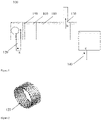
- FIG. 1 it schematically illustrates the structure of an embodiment of the economizer for a refrigeration system according to the present invention in general.
- the refrigeration system comprises a refrigerant circuit formed by sequentially connecting a compressor, a condenser, an expansion mechanism and an evaporator.
- the economizer 100 may be composed of a tank 110, a lead-in pipe 120, a gas outlet portion 130, a liquid outlet portion 140 and other components.
- the tank 110 is cylindrical and extends in a horizontal direction.
- the lead-in pipe 120 is arranged at one end of the tank 110 to introduce the gas-liquid two-phase refrigerant from the condenser, wherein the flow direction of the gas-liquid two-phase refrigerant is indicated by arrow a. It can be seen from FIG. 1 in conjunction with FIG. 2 that a threaded portion 121 is further provided on the inner wall of the lead-in pipe 120, so as to perform gas-liquid separation for the gas-liquid two-phase refrigerant by means of centrifugal action.
- the threaded portion 121 can greatly increase the flow resistance of the gas-liquid two-phase refrigerant.
- the advancement of the liquid and gas in the gas-liquid two-phase refrigerant will be hindered due to the increase of resistance.
- the gas in the gas-liquid two-phase refrigerant will become droplets and the droplets settle. Therefore, preliminary gas-liquid separation can be achieved by means of the threaded structure of the lead-in pipe 120.
- the threaded structure of the lead-in pipe 120 will help to generate centrifugal action, so that the gas-liquid two-phase refrigerant can rotate around the helical pipe wall to throw out the refrigerant droplets directly to the wall surface of the tank 110.
- the threaded portion 121 may be provided near the junction of the lead-in pipe 120 and the tank 110 (as shown in the circled portion in FIG 1 ), so as to perform effective gas-liquid separation for the gas-liquid two-phase refrigerant entering the tank 110.
- the length of the threaded portion 121 of the lead-in pipe 120 may be designed in a range of 20-30mm.
- the height of the threaded portion 121 of the lead-in pipe 120 may be designed in a range of 0.1-0.2mm.
- the helix angle of the threaded portion 121 of the lead-in pipe 120 may be designed in a range of 30°-60°.
- the threaded portion 121 of the lead-in pipe 120 may be configured as a continuous threaded structure, as shown in FIG. 2 .
- the threaded portion 121 can also be designed into an irregular shape, such as a discontinuous or asymmetric threaded structure.
- the gas outlet portion 130 may be arranged at the other end of the tank 110, so as to direct the gaseous refrigerant separated from the gas-liquid two-phase refrigerant back to the compressor, wherein the flow direction of the gaseous refrigerant is indicated by arrow b.
- the liquid outlet portion 140 may be arranged somewhere under the gas outlet portion 130, so as to direct the liquid refrigerant separated from the gas-liquid two-phase refrigerant to the evaporator, wherein the flow direction of the liquid refrigerant is indicated by arrow c.
- the tank 110 of the economizer 100 in the tank 110 of the economizer 100, three orifice plates 150 arranged side by side are provided near the lead-in pipe 120, and a number of orifices are provided on the orifice plates 150, so as to facilitate further gas-liquid separation of the gas-liquid two-phase refrigerant passing through it.
- the number of orifice plates 150 is not limited to three, and can be two, four, five or others within the allowable range of compressor power, as long as it is ensured that effective gas-liquid separation can be performed for the gas-liquid two-phase refrigerant.
- the position of the orifice plates 150, and the size and shape of the orifices can be adjusted according to actual needs.
- a liquid baffle 160 may also be arranged between the orifice plates 150 and the liquid outlet portion 140, wherein the liquid baffle 160 may be arranged at the top of the tank 100, i.e., extending downward from the top wall of the tank 100 as shown in FIG. 1 .
- the gas-liquid two-phase refrigerant passes through the orifice plates 150 and is blocked by the liquid baffle 160, so that most of the liquid refrigerant can settle in the lower part of the tank 110 and flows along the bottom wall of the tank 110 into the evaporator through the liquid outlet portion 140, while the gaseous refrigerant flows along the length direction of the tank 110 into the compressor through the gas outlet portion 130 of the tank 110.
- the gas outlet portion 130 may be arranged at the top of the tank 110, and the liquid outlet portion 140 may be arranged at the bottom of the tank 110, as shown in FIG. 1 .
- the economizer for a refrigeration system adopts a threaded structure on the inner wall of the lead-in pipe, so that the droplets in the gas-liquid two-phase refrigerant can settle by means of centrifugal action, thereby improving the gas-liquid separation efficiency of the gas-liquid two-phase refrigerant and then effectively reducing the liquid content of the gas in the gas outlet portion.
- the present invention further provides a refrigeration system provided with the aforementioned economizer.
- the refrigeration system comprises a cooling tower, a water chiller, a pumping device, and the like that are connected by pipelines, wherein the water chiller is composed of components such as compressor, condenser, throttling device and evaporator.
- the refrigeration system may be a multi-stage compression refrigeration system, and the compressor is a multi-stage compressor.
- the gas outlet portion of the economizer is connected to the intermediate suction port of the multi-stage compressor.
- the separated gas enters the intermediate suction port of the multi-stage compressor through the gas outlet portion, and is mixed with the intermediate pressure refrigerant gas which is formed after being sucked from the evaporator and compressed in the low-pressure stage, to enter the high-pressure stage for recompression.
- the refrigeration system provided with the aforementioned economizer can significantly improve the cooling capacity and operating efficiency without additional cost, so it is highly recommended to apply the aforementioned economizer to various refrigeration systems.
Landscapes
- Engineering & Computer Science (AREA)
- Physics & Mathematics (AREA)
- Mechanical Engineering (AREA)
- Thermal Sciences (AREA)
- General Engineering & Computer Science (AREA)
- Chemical & Material Sciences (AREA)
- Analytical Chemistry (AREA)
- Power Engineering (AREA)
- Air-Conditioning For Vehicles (AREA)
Abstract
Description
- The present invention relates to the technical field of heat exchange equipment, in particular to an economizer for a refrigeration system, and also relates to a refrigeration system provided with the economizer.
- It is known to those skilled in the art that economizer is an energy-saving device widely used in heat pump chillers in the refrigeration and air conditioning industry, which mainly functions to realize gas-liquid separation and improve unit operating efficiency. The gas-liquid two-phase refrigerant enters the tank of the economizer through a lead-in pipe. The gaseous portion of the refrigerant is completely separated from the liquid portion by the structure arranged in the tank of the economizer. The separated gaseous refrigerant enters the compressor through the gas outlet pipe to form a secondary suction, and the separated liquid refrigerant flows out through the liquid outlet pipe and enters the evaporator for evaporative refrigeration.
- As the gas-liquid two-phase refrigerant continuously enters the tank of the economizer through the lead-in pipe, the liquid refrigerant continuously gathers at the bottom of the tank, and then flows out from the liquid outlet pipe. The inner wall of the existing lead-in pipe is smooth, and the gas-liquid two-phase refrigerant enters the lead-in pipe without being seperated, so that the droplets of different particle sizes will directly enter the tank of the economizer along with the refrigerant gas flow. In addition, since the space in the economizer is narrow, if the gas-liquid separation cannot be carried out completely, it will inevitably lead to a large number of refrigerant droplets entering the compressor from the gas outlet pipe of the economizer. However, the compressor is a mechanical device that converts gas or vapor into liquid, so the consequence of a high liquid content in the gaseous refrigerant entering the compressor will be an increase in the power consumption of the compressor or liquid hammer.
- Therefore, there is an urgent need to find an economizer for a refrigeration system that can effectively realize gas-liquid separation.
- In view of the above, according to a first aspect of the present invention, an economizer for a refrigeration system is provided, which effectively solves the aforementioned problems and problems in other aspects existing in the prior art. In the economizer for a refrigeration system according to the present invention, the refrigeration system comprises a refrigerant circuit formed by sequentially connecting a compressor, a condenser, an expansion mechanism and an evaporator, wherein the economizer comprises: a tank extending in a horizontal direction; a lead-in pipe arranged at one end of the tank for introducing the gas-liquid two-phase refrigerant from the condenser; a gas outlet portion arranged at the other end of the tank for directing the gaseous refrigerant back to the compressor; and a liquid outlet portion arranged below the gas outlet portion for directing the liquid refrigerant to the evaporator; wherein a threaded portion is provided on the inner wall of the lead-in pipe for performing gas-liquid separation for the gas-liquid two-phase refrigerant by means of centrifugal action.
- Optionally, the threaded portion of the lead-in pipe is arranged near the junction of the lead-in pipe and the tank.
- Optionally, the length of the threaded portion of the lead-in pipe is in a range of 20-30mm.
- Optionally, the height of the threaded portion of the lead-in pipe is in a range of 0.1-0.2 mm.
- Optionally, the helix angle of the threaded portion of the lead-in pipe is in a range of 30°-60°.
- Optionally, the lead-in pipe is a 90° elbow pipe.
- Optionally, the threaded portion of the lead-in pipe is a continuous threaded structure.
- Optionally, a plurality of orifice plates arranged side by side for performing gas-liquid seperation for the gas-liquid two-phase refrigerant are provided near the lead-in pipe inside the tank.
- Optionally, a liquid baffle is provided between the orifice plates and the liquid outlet portion inside the tank.
- Optionally, the gas outlet portion is arranged at the top of the tank, and the liquid outlet portion is arranged at the bottom of the tank.
- In addition, according to a second aspect of the present invention, a refrigeration system comprising the economizer according to the first aspect of the invention is further provided. Optionally, the refrigeration system comprises the refrigeration circuit recited herein with reference to the first aspect of the invention. Optionally, the refrigeration circuit is formed by sequentially connecting the compressor, the condenser, the expansion mechanism and the evaporator. Optionally, the refrigeration system is a multi-stage compression refrigeration system, and the compressor is a multi-stage compressor, wherein the gas outlet portion of the economizer is connected to the intermediate suction port of the multi-stage compressor.
- It can be appreciated that the economizer for a refrigeration system according to the present invention, by arranging a threaded portion on the inner wall of the lead-in pipe, enables the gas-liquid two-phase refrigerant to better realize gas-liquid separation when entering the economizer tank by means of centrifugal action.
- The technical solutions of the present invention will be described in further detail below in conjunction with the accompanying drawings and embodiments by way of example only, wherein:
-
FIG. 1 shows a structural schematic diagram of an economizer for a refrigeration system; and -
FIG. 2 shows a partially enlarged structural schematic diagram of the lead-in pipe of the economizer for a refrigeration system according toFIG 1 . - Some embodiments of the present invention will be described in detail below with reference to the accompanying drawings. It should be noted that orientation terms such as upper, lower, left, right, front, rear, inner side, outer side, top and bottom mentioned or possibly mentioned in this specification are defined relative to the configurations illustrated in the respective drawings. They are relative concepts, so they may change accordingly according to their different locations and different states of use. Therefore, these and other orientation terms shall not be construed as restrictive terms.
- As shown in
FIG. 1 , it schematically illustrates the structure of an embodiment of the economizer for a refrigeration system according to the present invention in general. The refrigeration system comprises a refrigerant circuit formed by sequentially connecting a compressor, a condenser, an expansion mechanism and an evaporator. It should be noted that, in order to better illustrate the economizer for a refrigeration system according to the present invention, other components in the refrigeration system other than the economizer are not shown here. As can be seen fromFIG. 1 , theeconomizer 100 may be composed of atank 110, a lead-inpipe 120, agas outlet portion 130, aliquid outlet portion 140 and other components. Thetank 110 is cylindrical and extends in a horizontal direction. The lead-inpipe 120 is arranged at one end of thetank 110 to introduce the gas-liquid two-phase refrigerant from the condenser, wherein the flow direction of the gas-liquid two-phase refrigerant is indicated by arrow a. It can be seen fromFIG. 1 in conjunction withFIG. 2 that a threadedportion 121 is further provided on the inner wall of the lead-inpipe 120, so as to perform gas-liquid separation for the gas-liquid two-phase refrigerant by means of centrifugal action. - When the gas-liquid two-phase refrigerant enters the
tank 110 through the lead-inpipe 120, the threadedportion 121 can greatly increase the flow resistance of the gas-liquid two-phase refrigerant. The advancement of the liquid and gas in the gas-liquid two-phase refrigerant will be hindered due to the increase of resistance. In particular, as the pressure increases, the gas in the gas-liquid two-phase refrigerant will become droplets and the droplets settle. Therefore, preliminary gas-liquid separation can be achieved by means of the threaded structure of the lead-inpipe 120. In addition, those skilled in the art can appreciate that the threaded structure of the lead-inpipe 120 will help to generate centrifugal action, so that the gas-liquid two-phase refrigerant can rotate around the helical pipe wall to throw out the refrigerant droplets directly to the wall surface of thetank 110. - With continued reference to
FIG. 1 , the threadedportion 121 may be provided near the junction of the lead-inpipe 120 and the tank 110 (as shown in the circled portion inFIG 1 ), so as to perform effective gas-liquid separation for the gas-liquid two-phase refrigerant entering thetank 110. - In a preferred embodiment according to the present invention, the length of the threaded
portion 121 of the lead-inpipe 120 may be designed in a range of 20-30mm. In addition, the height of the threadedportion 121 of the lead-inpipe 120 may be designed in a range of 0.1-0.2mm. Furthermore, the helix angle of the threadedportion 121 of the lead-inpipe 120 may be designed in a range of 30°-60°. - As an example, in order to facilitate manufacture, the threaded
portion 121 of the lead-inpipe 120 may be configured as a continuous threaded structure, as shown inFIG. 2 . Of course, in addition to being designed into a regular shape, such as a continuous threaded structure as shown inFIG. 2 , the threadedportion 121 can also be designed into an irregular shape, such as a discontinuous or asymmetric threaded structure. - In the embodiment shown in
FIG. 1 , in theeconomizer 100, thegas outlet portion 130 may be arranged at the other end of thetank 110, so as to direct the gaseous refrigerant separated from the gas-liquid two-phase refrigerant back to the compressor, wherein the flow direction of the gaseous refrigerant is indicated by arrow b. Theliquid outlet portion 140 may be arranged somewhere under thegas outlet portion 130, so as to direct the liquid refrigerant separated from the gas-liquid two-phase refrigerant to the evaporator, wherein the flow direction of the liquid refrigerant is indicated by arrow c. - In addition, in the aforementioned embodiment, in the
tank 110 of theeconomizer 100, threeorifice plates 150 arranged side by side are provided near the lead-inpipe 120, and a number of orifices are provided on theorifice plates 150, so as to facilitate further gas-liquid separation of the gas-liquid two-phase refrigerant passing through it. Of course, those skilled in the art can appreciate that the number oforifice plates 150 is not limited to three, and can be two, four, five or others within the allowable range of compressor power, as long as it is ensured that effective gas-liquid separation can be performed for the gas-liquid two-phase refrigerant. In addition, it can be appreciated that the position of theorifice plates 150, and the size and shape of the orifices can be adjusted according to actual needs. - Furthermore, in the
tank 110 of theeconomizer 100, aliquid baffle 160 may also be arranged between theorifice plates 150 and theliquid outlet portion 140, wherein theliquid baffle 160 may be arranged at the top of thetank 100, i.e., extending downward from the top wall of thetank 100 as shown inFIG. 1 . The gas-liquid two-phase refrigerant passes through theorifice plates 150 and is blocked by theliquid baffle 160, so that most of the liquid refrigerant can settle in the lower part of thetank 110 and flows along the bottom wall of thetank 110 into the evaporator through theliquid outlet portion 140, while the gaseous refrigerant flows along the length direction of thetank 110 into the compressor through thegas outlet portion 130 of thetank 110. - In order to obtain gaseous refrigerant and liquid refrigerant more conveniently, the
gas outlet portion 130 may be arranged at the top of thetank 110, and theliquid outlet portion 140 may be arranged at the bottom of thetank 110, as shown inFIG. 1 . - To sum up, the economizer for a refrigeration system according to the present invention adopts a threaded structure on the inner wall of the lead-in pipe, so that the droplets in the gas-liquid two-phase refrigerant can settle by means of centrifugal action, thereby improving the gas-liquid separation efficiency of the gas-liquid two-phase refrigerant and then effectively reducing the liquid content of the gas in the gas outlet portion.
- In addition, the present invention further provides a refrigeration system provided with the aforementioned economizer. The refrigeration system comprises a cooling tower, a water chiller, a pumping device, and the like that are connected by pipelines, wherein the water chiller is composed of components such as compressor, condenser, throttling device and evaporator. The refrigeration system may be a multi-stage compression refrigeration system, and the compressor is a multi-stage compressor. The gas outlet portion of the economizer is connected to the intermediate suction port of the multi-stage compressor. The separated gas enters the intermediate suction port of the multi-stage compressor through the gas outlet portion, and is mixed with the intermediate pressure refrigerant gas which is formed after being sucked from the evaporator and compressed in the low-pressure stage, to enter the high-pressure stage for recompression. As mentioned above, the refrigeration system provided with the aforementioned economizer can significantly improve the cooling capacity and operating efficiency without additional cost, so it is highly recommended to apply the aforementioned economizer to various refrigeration systems.
- Some specific embodiments are listed above to illustrate in detail an economizer for a refrigeration system, and a refrigeration system provided with the economizer according to the present invention. These individual examples are only used to illustrate the principle of the present invention and the implementations thereof, but not to limit the present invention. Those skilled in the art may, without departing from the spirit and scope of the present invention, make various modifications and improvements. For example, the lead-in pipe can be designed as a 90° elbow pipe. Therefore, all equivalent technical solutions shall belong to the scope of the present invention and be defined by the various claims of the present invention.
Claims (11)
- An economizer for a refrigeration system, the refrigeration system comprising a refrigerant circuit formed by sequentially connecting a compressor, a condenser, an expansion mechanism and an evaporator, wherein the economizer comprises:a tank (110) extending in a horizontal direction;a lead-in pipe (120) arranged at one end of the tank for introducing gas-liquid two-phase refrigerant from the condenser;a gas outlet portion (130) arranged at the other end of the tank (110) for directing gaseous refrigerant back to the compressor; anda liquid outlet portion (140) arranged below the gas outlet portion (130) for directing liquid refrigerant to the evaporator,wherein a threaded portion (121) is provided on an inner wall of the lead-in pipe (120) for performing gas-liquid separation for the gas-liquid two-phase refrigerant by means of centrifugal action.
- The economizer for a refrigeration system according to claim 1, wherein the threaded portion (121) of the lead-in pipe (120) is arranged near a junction of the lead-in pipe (120) and the tank (110).
- The economizer for a refrigeration system according to claim 1 or 2, wherein a length of the threaded portion (121) of the lead-in pipe (120) is in a range of 20-30 mm.
- The economizer for a refrigeration system according to any of claims 1 to 3, wherein a height of the threaded portion (121) of the lead-in pipe (120) is in a range of 0.1-0.2 mm.
- The economizer for a refrigeration system according to any preceding claim, wherein a helix angle of the threaded portion (121) of the lead-in pipe (120) is in a range of 30°-60°.
- The economizer for a refrigeration system according to any preceding claim, wherein the lead-in pipe (120) is a 90° elbow pipe.
- The economizer for a refrigeration system according to any preceding claim, wherein the threaded portion (121) of the lead-in pipe (120) is a continuous threaded structure.
- The economizer for a refrigeration system according to any preceding claim, wherein a plurality of orifice plates (150) arranged side by side for performing gas-liquid separation for the gas-liquid two-phase refrigerant are provided near the lead-in pipe (120) inside the tank (110).
- The economizer for a refrigeration system according to claim 8, wherein a liquid baffle (160) is provided between the orifice plates (150) and the liquid outlet portion (140) inside the tank (110).
- The economizer for a refrigeration system according to any preceding claim, wherein the gas outlet portion (130) is arranged at the top of the tank (110), and the liquid outlet portion (140) is arranged at the bottom of the tank (110).
- A refrigeration system comprising the economizer (100) for a refrigeration system according to any preceding claim, wherein the refrigeration system is a multi-stage compression refrigeration system, the compressor is a multi-stage compressor, and a gas outlet portion (130) of the economizer (100) is connected to an intermediate suction port of the multi-stage compressor.
Applications Claiming Priority (1)
| Application Number | Priority Date | Filing Date | Title |
|---|---|---|---|
| CN202110672474.0A CN115493317A (en) | 2021-06-17 | 2021-06-17 | Economizers for refrigeration systems and refrigeration systems |
Publications (2)
| Publication Number | Publication Date |
|---|---|
| EP4105576A1 true EP4105576A1 (en) | 2022-12-21 |
| EP4105576B1 EP4105576B1 (en) | 2024-04-24 |
Family
ID=82117216
Family Applications (1)
| Application Number | Title | Priority Date | Filing Date |
|---|---|---|---|
| EP22179463.9A Active EP4105576B1 (en) | 2021-06-17 | 2022-06-16 | Economizer for refrigeration system and refrigeration system |
Country Status (2)
| Country | Link |
|---|---|
| EP (1) | EP4105576B1 (en) |
| CN (1) | CN115493317A (en) |
Cited By (1)
| Publication number | Priority date | Publication date | Assignee | Title |
|---|---|---|---|---|
| US20220333829A1 (en) * | 2021-04-20 | 2022-10-20 | Carrier Corporation | Economizer and air conditioning system |
Citations (3)
| Publication number | Priority date | Publication date | Assignee | Title |
|---|---|---|---|---|
| JPH05223359A (en) * | 1991-12-06 | 1993-08-31 | Nippondenso Co Ltd | Freezing cycle |
| US20150096315A1 (en) * | 2013-10-03 | 2015-04-09 | Carrier Corporation | Flash Tank Economizer for Two Stage Centrifugal Water Chillers |
| EP3502589A1 (en) * | 2016-08-22 | 2019-06-26 | GD Midea Heating & Ventilating Equipment Co., Ltd. | Horizontal gas-liquid separator for air conditioner, and air conditioner |
Family Cites Families (6)
| Publication number | Priority date | Publication date | Assignee | Title |
|---|---|---|---|---|
| CN204165295U (en) * | 2014-09-29 | 2015-02-18 | 广州日立冷机有限公司 | The economizer that centrifugal gas-liquid is separated |
| CN105135766B (en) * | 2015-09-13 | 2017-06-20 | 华南理工大学 | A kind of bidirectional screw flash vessel for being applied to Gas-supplying enthalpy-increasing heat pump type air conditioning system |
| CN205860576U (en) * | 2016-07-06 | 2017-01-04 | 杭州赛富特设备有限公司 | A kind of centrifugal flash distillation economizer |
| JP6767196B2 (en) * | 2016-08-02 | 2020-10-14 | 荏原冷熱システム株式会社 | Economizer |
| CN109990515B (en) * | 2019-04-30 | 2023-10-03 | 安徽美乐柯制冷空调设备有限公司 | Heat exchange gas-liquid separator with economizer function |
| CN110895063A (en) * | 2019-10-14 | 2020-03-20 | 山西臣功新能源科技有限公司 | air source heat pump |
-
2021
- 2021-06-17 CN CN202110672474.0A patent/CN115493317A/en active Pending
-
2022
- 2022-06-16 EP EP22179463.9A patent/EP4105576B1/en active Active
Patent Citations (3)
| Publication number | Priority date | Publication date | Assignee | Title |
|---|---|---|---|---|
| JPH05223359A (en) * | 1991-12-06 | 1993-08-31 | Nippondenso Co Ltd | Freezing cycle |
| US20150096315A1 (en) * | 2013-10-03 | 2015-04-09 | Carrier Corporation | Flash Tank Economizer for Two Stage Centrifugal Water Chillers |
| EP3502589A1 (en) * | 2016-08-22 | 2019-06-26 | GD Midea Heating & Ventilating Equipment Co., Ltd. | Horizontal gas-liquid separator for air conditioner, and air conditioner |
Cited By (2)
| Publication number | Priority date | Publication date | Assignee | Title |
|---|---|---|---|---|
| US20220333829A1 (en) * | 2021-04-20 | 2022-10-20 | Carrier Corporation | Economizer and air conditioning system |
| US12247767B2 (en) * | 2021-04-20 | 2025-03-11 | Carrier Corporation | Economizer and air conditioning system |
Also Published As
| Publication number | Publication date |
|---|---|
| EP4105576B1 (en) | 2024-04-24 |
| CN115493317A (en) | 2022-12-20 |
Similar Documents
| Publication | Publication Date | Title |
|---|---|---|
| US9890977B2 (en) | Flash tank economizer for two stage centrifugal water chillers | |
| US10222104B2 (en) | Distributor and turbo refrigerating machine and evaporator having the same | |
| JP5452367B2 (en) | Gas-liquid separator and refrigeration cycle apparatus | |
| US20240393023A1 (en) | Economizer and refrigeration system comprising same | |
| JPWO2014103436A1 (en) | Refrigeration cycle equipment | |
| CN102589211A (en) | Efficient flash-tank with liquid-distribution manifold branches and used for vapor compression refrigeration system | |
| CN113713508A (en) | Centrifugal separation pipe, gas-liquid separation device and refrigeration system with device | |
| JP2015108463A (en) | Heat exchanger and refrigeration cycle device | |
| EP4105576B1 (en) | Economizer for refrigeration system and refrigeration system | |
| KR102104893B1 (en) | Evaporator and Turbo chiller comprising the same | |
| CN105444483B (en) | A kind of flooded screw mechanism ice maker group | |
| CN105299944B (en) | A kind of full-liquid type central air conditioner system | |
| WO2024021698A1 (en) | Shell-and-tube heat exchanger and air conditioning unit | |
| JP2013257081A (en) | Gas/liquid separating heat exchanger and air conditioner | |
| US11175078B2 (en) | Gas-liquid separator and air conditioner including the same | |
| CN102345944A (en) | Built-in oil separating condenser | |
| CN204128244U (en) | A kind of hydrocone type evaporimeter | |
| CN106225274A (en) | A kind of vortex parallel full-liquid type handpiece Water Chilling Units | |
| CN104006588A (en) | Three-stage separated efficient horizontal type oil distribution device | |
| CN205192015U (en) | Hydraulic filling formula screw rod mechanism ice maker group | |
| CN109642760B (en) | Refrigerant distributor for falling film evaporator | |
| CN204388412U (en) | A kind of refrigeration system | |
| CN204202262U (en) | Three grades of separate type high efficient horizontals divide oily device | |
| CN206440039U (en) | A kind of air-conditioning system of use gravity force liquid-supply | |
| CN205191970U (en) | Hydraulic filling formula central air -conditioning system |
Legal Events
| Date | Code | Title | Description |
|---|---|---|---|
| PUAI | Public reference made under article 153(3) epc to a published international application that has entered the european phase |
Free format text: ORIGINAL CODE: 0009012 |
|
| STAA | Information on the status of an ep patent application or granted ep patent |
Free format text: STATUS: THE APPLICATION HAS BEEN PUBLISHED |
|
| AK | Designated contracting states |
Kind code of ref document: A1 Designated state(s): AL AT BE BG CH CY CZ DE DK EE ES FI FR GB GR HR HU IE IS IT LI LT LU LV MC MK MT NL NO PL PT RO RS SE SI SK SM TR |
|
| STAA | Information on the status of an ep patent application or granted ep patent |
Free format text: STATUS: REQUEST FOR EXAMINATION WAS MADE |
|
| 17P | Request for examination filed |
Effective date: 20230621 |
|
| RBV | Designated contracting states (corrected) |
Designated state(s): AL AT BE BG CH CY CZ DE DK EE ES FI FR GB GR HR HU IE IS IT LI LT LU LV MC MK MT NL NO PL PT RO RS SE SI SK SM TR |
|
| GRAP | Despatch of communication of intention to grant a patent |
Free format text: ORIGINAL CODE: EPIDOSNIGR1 |
|
| STAA | Information on the status of an ep patent application or granted ep patent |
Free format text: STATUS: GRANT OF PATENT IS INTENDED |
|
| INTG | Intention to grant announced |
Effective date: 20231129 |
|
| GRAS | Grant fee paid |
Free format text: ORIGINAL CODE: EPIDOSNIGR3 |
|
| GRAA | (expected) grant |
Free format text: ORIGINAL CODE: 0009210 |
|
| STAA | Information on the status of an ep patent application or granted ep patent |
Free format text: STATUS: THE PATENT HAS BEEN GRANTED |
|
| AK | Designated contracting states |
Kind code of ref document: B1 Designated state(s): AL AT BE BG CH CY CZ DE DK EE ES FI FR GB GR HR HU IE IS IT LI LT LU LV MC MK MT NL NO PL PT RO RS SE SI SK SM TR |
|
| REG | Reference to a national code |
Ref country code: GB Ref legal event code: FG4D |
|
| REG | Reference to a national code |
Ref country code: CH Ref legal event code: EP |
|
| REG | Reference to a national code |
Ref country code: DE Ref legal event code: R096 Ref document number: 602022003019 Country of ref document: DE |
|
| REG | Reference to a national code |
Ref country code: IE Ref legal event code: FG4D |
|
| REG | Reference to a national code |
Ref country code: LT Ref legal event code: MG9D |
|
| REG | Reference to a national code |
Ref country code: NL Ref legal event code: MP Effective date: 20240424 |
|
| REG | Reference to a national code |
Ref country code: AT Ref legal event code: MK05 Ref document number: 1679994 Country of ref document: AT Kind code of ref document: T Effective date: 20240424 |
|
| PG25 | Lapsed in a contracting state [announced via postgrant information from national office to epo] |
Ref country code: NL Free format text: LAPSE BECAUSE OF FAILURE TO SUBMIT A TRANSLATION OF THE DESCRIPTION OR TO PAY THE FEE WITHIN THE PRESCRIBED TIME-LIMIT Effective date: 20240424 |
|
| PG25 | Lapsed in a contracting state [announced via postgrant information from national office to epo] |
Ref country code: NL Free format text: LAPSE BECAUSE OF FAILURE TO SUBMIT A TRANSLATION OF THE DESCRIPTION OR TO PAY THE FEE WITHIN THE PRESCRIBED TIME-LIMIT Effective date: 20240424 |
|
| PG25 | Lapsed in a contracting state [announced via postgrant information from national office to epo] |
Ref country code: IS Free format text: LAPSE BECAUSE OF FAILURE TO SUBMIT A TRANSLATION OF THE DESCRIPTION OR TO PAY THE FEE WITHIN THE PRESCRIBED TIME-LIMIT Effective date: 20240824 |
|
| PG25 | Lapsed in a contracting state [announced via postgrant information from national office to epo] |
Ref country code: BG Free format text: LAPSE BECAUSE OF FAILURE TO SUBMIT A TRANSLATION OF THE DESCRIPTION OR TO PAY THE FEE WITHIN THE PRESCRIBED TIME-LIMIT Effective date: 20240424 |
|
| PG25 | Lapsed in a contracting state [announced via postgrant information from national office to epo] |
Ref country code: HR Free format text: LAPSE BECAUSE OF FAILURE TO SUBMIT A TRANSLATION OF THE DESCRIPTION OR TO PAY THE FEE WITHIN THE PRESCRIBED TIME-LIMIT Effective date: 20240424 Ref country code: FI Free format text: LAPSE BECAUSE OF FAILURE TO SUBMIT A TRANSLATION OF THE DESCRIPTION OR TO PAY THE FEE WITHIN THE PRESCRIBED TIME-LIMIT Effective date: 20240424 |
|
| PG25 | Lapsed in a contracting state [announced via postgrant information from national office to epo] |
Ref country code: GR Free format text: LAPSE BECAUSE OF FAILURE TO SUBMIT A TRANSLATION OF THE DESCRIPTION OR TO PAY THE FEE WITHIN THE PRESCRIBED TIME-LIMIT Effective date: 20240725 |
|
| PG25 | Lapsed in a contracting state [announced via postgrant information from national office to epo] |
Ref country code: PT Free format text: LAPSE BECAUSE OF FAILURE TO SUBMIT A TRANSLATION OF THE DESCRIPTION OR TO PAY THE FEE WITHIN THE PRESCRIBED TIME-LIMIT Effective date: 20240826 |
|
| PG25 | Lapsed in a contracting state [announced via postgrant information from national office to epo] |
Ref country code: ES Free format text: LAPSE BECAUSE OF FAILURE TO SUBMIT A TRANSLATION OF THE DESCRIPTION OR TO PAY THE FEE WITHIN THE PRESCRIBED TIME-LIMIT Effective date: 20240424 |
|
| PG25 | Lapsed in a contracting state [announced via postgrant information from national office to epo] |
Ref country code: AT Free format text: LAPSE BECAUSE OF FAILURE TO SUBMIT A TRANSLATION OF THE DESCRIPTION OR TO PAY THE FEE WITHIN THE PRESCRIBED TIME-LIMIT Effective date: 20240424 |
|
| PG25 | Lapsed in a contracting state [announced via postgrant information from national office to epo] |
Ref country code: PL Free format text: LAPSE BECAUSE OF FAILURE TO SUBMIT A TRANSLATION OF THE DESCRIPTION OR TO PAY THE FEE WITHIN THE PRESCRIBED TIME-LIMIT Effective date: 20240424 |
|
| PG25 | Lapsed in a contracting state [announced via postgrant information from national office to epo] |
Ref country code: LV Free format text: LAPSE BECAUSE OF FAILURE TO SUBMIT A TRANSLATION OF THE DESCRIPTION OR TO PAY THE FEE WITHIN THE PRESCRIBED TIME-LIMIT Effective date: 20240424 |
|
| PG25 | Lapsed in a contracting state [announced via postgrant information from national office to epo] |
Ref country code: PT Free format text: LAPSE BECAUSE OF FAILURE TO SUBMIT A TRANSLATION OF THE DESCRIPTION OR TO PAY THE FEE WITHIN THE PRESCRIBED TIME-LIMIT Effective date: 20240826 Ref country code: PL Free format text: LAPSE BECAUSE OF FAILURE TO SUBMIT A TRANSLATION OF THE DESCRIPTION OR TO PAY THE FEE WITHIN THE PRESCRIBED TIME-LIMIT Effective date: 20240424 Ref country code: NO Free format text: LAPSE BECAUSE OF FAILURE TO SUBMIT A TRANSLATION OF THE DESCRIPTION OR TO PAY THE FEE WITHIN THE PRESCRIBED TIME-LIMIT Effective date: 20240724 Ref country code: LV Free format text: LAPSE BECAUSE OF FAILURE TO SUBMIT A TRANSLATION OF THE DESCRIPTION OR TO PAY THE FEE WITHIN THE PRESCRIBED TIME-LIMIT Effective date: 20240424 Ref country code: IS Free format text: LAPSE BECAUSE OF FAILURE TO SUBMIT A TRANSLATION OF THE DESCRIPTION OR TO PAY THE FEE WITHIN THE PRESCRIBED TIME-LIMIT Effective date: 20240824 Ref country code: HR Free format text: LAPSE BECAUSE OF FAILURE TO SUBMIT A TRANSLATION OF THE DESCRIPTION OR TO PAY THE FEE WITHIN THE PRESCRIBED TIME-LIMIT Effective date: 20240424 Ref country code: GR Free format text: LAPSE BECAUSE OF FAILURE TO SUBMIT A TRANSLATION OF THE DESCRIPTION OR TO PAY THE FEE WITHIN THE PRESCRIBED TIME-LIMIT Effective date: 20240725 Ref country code: FI Free format text: LAPSE BECAUSE OF FAILURE TO SUBMIT A TRANSLATION OF THE DESCRIPTION OR TO PAY THE FEE WITHIN THE PRESCRIBED TIME-LIMIT Effective date: 20240424 Ref country code: ES Free format text: LAPSE BECAUSE OF FAILURE TO SUBMIT A TRANSLATION OF THE DESCRIPTION OR TO PAY THE FEE WITHIN THE PRESCRIBED TIME-LIMIT Effective date: 20240424 Ref country code: BG Free format text: LAPSE BECAUSE OF FAILURE TO SUBMIT A TRANSLATION OF THE DESCRIPTION OR TO PAY THE FEE WITHIN THE PRESCRIBED TIME-LIMIT Effective date: 20240424 Ref country code: AT Free format text: LAPSE BECAUSE OF FAILURE TO SUBMIT A TRANSLATION OF THE DESCRIPTION OR TO PAY THE FEE WITHIN THE PRESCRIBED TIME-LIMIT Effective date: 20240424 Ref country code: RS Free format text: LAPSE BECAUSE OF FAILURE TO SUBMIT A TRANSLATION OF THE DESCRIPTION OR TO PAY THE FEE WITHIN THE PRESCRIBED TIME-LIMIT Effective date: 20240724 |
|
| PG25 | Lapsed in a contracting state [announced via postgrant information from national office to epo] |
Ref country code: DK Free format text: LAPSE BECAUSE OF FAILURE TO SUBMIT A TRANSLATION OF THE DESCRIPTION OR TO PAY THE FEE WITHIN THE PRESCRIBED TIME-LIMIT Effective date: 20240424 |
|
| PG25 | Lapsed in a contracting state [announced via postgrant information from national office to epo] |
Ref country code: EE Free format text: LAPSE BECAUSE OF FAILURE TO SUBMIT A TRANSLATION OF THE DESCRIPTION OR TO PAY THE FEE WITHIN THE PRESCRIBED TIME-LIMIT Effective date: 20240424 |
|
| PG25 | Lapsed in a contracting state [announced via postgrant information from national office to epo] |
Ref country code: CZ Free format text: LAPSE BECAUSE OF FAILURE TO SUBMIT A TRANSLATION OF THE DESCRIPTION OR TO PAY THE FEE WITHIN THE PRESCRIBED TIME-LIMIT Effective date: 20240424 |
|
| PG25 | Lapsed in a contracting state [announced via postgrant information from national office to epo] |
Ref country code: RO Free format text: LAPSE BECAUSE OF FAILURE TO SUBMIT A TRANSLATION OF THE DESCRIPTION OR TO PAY THE FEE WITHIN THE PRESCRIBED TIME-LIMIT Effective date: 20240424 Ref country code: SK Free format text: LAPSE BECAUSE OF FAILURE TO SUBMIT A TRANSLATION OF THE DESCRIPTION OR TO PAY THE FEE WITHIN THE PRESCRIBED TIME-LIMIT Effective date: 20240424 |
|
| REG | Reference to a national code |
Ref country code: DE Ref legal event code: R097 Ref document number: 602022003019 Country of ref document: DE |
|
| PG25 | Lapsed in a contracting state [announced via postgrant information from national office to epo] |
Ref country code: SM Free format text: LAPSE BECAUSE OF FAILURE TO SUBMIT A TRANSLATION OF THE DESCRIPTION OR TO PAY THE FEE WITHIN THE PRESCRIBED TIME-LIMIT Effective date: 20240424 |
|
| PG25 | Lapsed in a contracting state [announced via postgrant information from national office to epo] |
Ref country code: SM Free format text: LAPSE BECAUSE OF FAILURE TO SUBMIT A TRANSLATION OF THE DESCRIPTION OR TO PAY THE FEE WITHIN THE PRESCRIBED TIME-LIMIT Effective date: 20240424 Ref country code: SK Free format text: LAPSE BECAUSE OF FAILURE TO SUBMIT A TRANSLATION OF THE DESCRIPTION OR TO PAY THE FEE WITHIN THE PRESCRIBED TIME-LIMIT Effective date: 20240424 Ref country code: RO Free format text: LAPSE BECAUSE OF FAILURE TO SUBMIT A TRANSLATION OF THE DESCRIPTION OR TO PAY THE FEE WITHIN THE PRESCRIBED TIME-LIMIT Effective date: 20240424 Ref country code: EE Free format text: LAPSE BECAUSE OF FAILURE TO SUBMIT A TRANSLATION OF THE DESCRIPTION OR TO PAY THE FEE WITHIN THE PRESCRIBED TIME-LIMIT Effective date: 20240424 Ref country code: DK Free format text: LAPSE BECAUSE OF FAILURE TO SUBMIT A TRANSLATION OF THE DESCRIPTION OR TO PAY THE FEE WITHIN THE PRESCRIBED TIME-LIMIT Effective date: 20240424 Ref country code: CZ Free format text: LAPSE BECAUSE OF FAILURE TO SUBMIT A TRANSLATION OF THE DESCRIPTION OR TO PAY THE FEE WITHIN THE PRESCRIBED TIME-LIMIT Effective date: 20240424 Ref country code: MC Free format text: LAPSE BECAUSE OF FAILURE TO SUBMIT A TRANSLATION OF THE DESCRIPTION OR TO PAY THE FEE WITHIN THE PRESCRIBED TIME-LIMIT Effective date: 20240424 |
|
| PG25 | Lapsed in a contracting state [announced via postgrant information from national office to epo] |
Ref country code: LU Free format text: LAPSE BECAUSE OF NON-PAYMENT OF DUE FEES Effective date: 20240616 |
|
| PLBE | No opposition filed within time limit |
Free format text: ORIGINAL CODE: 0009261 |
|
| STAA | Information on the status of an ep patent application or granted ep patent |
Free format text: STATUS: NO OPPOSITION FILED WITHIN TIME LIMIT |
|
| 26N | No opposition filed |
Effective date: 20250127 |
|
| PG25 | Lapsed in a contracting state [announced via postgrant information from national office to epo] |
Ref country code: IE Free format text: LAPSE BECAUSE OF NON-PAYMENT OF DUE FEES Effective date: 20240616 |
|
| PG25 | Lapsed in a contracting state [announced via postgrant information from national office to epo] |
Ref country code: BE Free format text: LAPSE BECAUSE OF NON-PAYMENT OF DUE FEES Effective date: 20240630 Ref country code: SI Free format text: LAPSE BECAUSE OF FAILURE TO SUBMIT A TRANSLATION OF THE DESCRIPTION OR TO PAY THE FEE WITHIN THE PRESCRIBED TIME-LIMIT Effective date: 20240424 |
|
| REG | Reference to a national code |
Ref country code: BE Ref legal event code: MM Effective date: 20240630 |
|
| PGFP | Annual fee paid to national office [announced via postgrant information from national office to epo] |
Ref country code: DE Payment date: 20250520 Year of fee payment: 4 |
|
| PGFP | Annual fee paid to national office [announced via postgrant information from national office to epo] |
Ref country code: FR Payment date: 20250520 Year of fee payment: 4 |
|
| PG25 | Lapsed in a contracting state [announced via postgrant information from national office to epo] |
Ref country code: SE Free format text: LAPSE BECAUSE OF FAILURE TO SUBMIT A TRANSLATION OF THE DESCRIPTION OR TO PAY THE FEE WITHIN THE PRESCRIBED TIME-LIMIT Effective date: 20240424 |
|
| PG25 | Lapsed in a contracting state [announced via postgrant information from national office to epo] |
Ref country code: CY Free format text: LAPSE BECAUSE OF FAILURE TO SUBMIT A TRANSLATION OF THE DESCRIPTION OR TO PAY THE FEE WITHIN THE PRESCRIBED TIME-LIMIT; INVALID AB INITIO Effective date: 20220616 |
|
| REG | Reference to a national code |
Ref country code: CH Ref legal event code: H13 Free format text: ST27 STATUS EVENT CODE: U-0-0-H10-H13 (AS PROVIDED BY THE NATIONAL OFFICE) Effective date: 20260127 |
|
| PG25 | Lapsed in a contracting state [announced via postgrant information from national office to epo] |
Ref country code: IT Free format text: LAPSE BECAUSE OF FAILURE TO SUBMIT A TRANSLATION OF THE DESCRIPTION OR TO PAY THE FEE WITHIN THE PRESCRIBED TIME-LIMIT Effective date: 20240424 |
|
| PG25 | Lapsed in a contracting state [announced via postgrant information from national office to epo] |
Ref country code: HU Free format text: LAPSE BECAUSE OF FAILURE TO SUBMIT A TRANSLATION OF THE DESCRIPTION OR TO PAY THE FEE WITHIN THE PRESCRIBED TIME-LIMIT; INVALID AB INITIO Effective date: 20220616 |
|
| PG25 | Lapsed in a contracting state [announced via postgrant information from national office to epo] |
Ref country code: CH Free format text: LAPSE BECAUSE OF NON-PAYMENT OF DUE FEES Effective date: 20250630 |