EP4105521A1 - Power transmission device for work vehicle - Google Patents
Power transmission device for work vehicle Download PDFInfo
- Publication number
- EP4105521A1 EP4105521A1 EP22177323.7A EP22177323A EP4105521A1 EP 4105521 A1 EP4105521 A1 EP 4105521A1 EP 22177323 A EP22177323 A EP 22177323A EP 4105521 A1 EP4105521 A1 EP 4105521A1
- Authority
- EP
- European Patent Office
- Prior art keywords
- gear
- cover
- power transmission
- transmission device
- lower portion
- Prior art date
- Legal status (The legal status is an assumption and is not a legal conclusion. Google has not performed a legal analysis and makes no representation as to the accuracy of the status listed.)
- Granted
Links
Images




Classifications
-
- F—MECHANICAL ENGINEERING; LIGHTING; HEATING; WEAPONS; BLASTING
- F16—ENGINEERING ELEMENTS AND UNITS; GENERAL MEASURES FOR PRODUCING AND MAINTAINING EFFECTIVE FUNCTIONING OF MACHINES OR INSTALLATIONS; THERMAL INSULATION IN GENERAL
- F16H—GEARING
- F16H57/00—General details of gearing
- F16H57/02—Gearboxes; Mounting gearing therein
- F16H57/021—Shaft support structures, e.g. partition walls, bearing eyes, casing walls or covers with bearings
-
- F—MECHANICAL ENGINEERING; LIGHTING; HEATING; WEAPONS; BLASTING
- F16—ENGINEERING ELEMENTS AND UNITS; GENERAL MEASURES FOR PRODUCING AND MAINTAINING EFFECTIVE FUNCTIONING OF MACHINES OR INSTALLATIONS; THERMAL INSULATION IN GENERAL
- F16H—GEARING
- F16H57/00—General details of gearing
- F16H57/02—Gearboxes; Mounting gearing therein
- F16H57/031—Gearboxes; Mounting gearing therein characterised by covers or lids for gearboxes
-
- F—MECHANICAL ENGINEERING; LIGHTING; HEATING; WEAPONS; BLASTING
- F16—ENGINEERING ELEMENTS AND UNITS; GENERAL MEASURES FOR PRODUCING AND MAINTAINING EFFECTIVE FUNCTIONING OF MACHINES OR INSTALLATIONS; THERMAL INSULATION IN GENERAL
- F16H—GEARING
- F16H57/00—General details of gearing
- F16H57/02—Gearboxes; Mounting gearing therein
- F16H57/037—Gearboxes for accommodating differential gearings
-
- F—MECHANICAL ENGINEERING; LIGHTING; HEATING; WEAPONS; BLASTING
- F16—ENGINEERING ELEMENTS AND UNITS; GENERAL MEASURES FOR PRODUCING AND MAINTAINING EFFECTIVE FUNCTIONING OF MACHINES OR INSTALLATIONS; THERMAL INSULATION IN GENERAL
- F16H—GEARING
- F16H57/00—General details of gearing
- F16H57/04—Features relating to lubrication or cooling or heating
- F16H57/0409—Features relating to lubrication or cooling or heating characterised by increasing efficiency, e.g. by reducing splash losses
-
- F—MECHANICAL ENGINEERING; LIGHTING; HEATING; WEAPONS; BLASTING
- F16—ENGINEERING ELEMENTS AND UNITS; GENERAL MEASURES FOR PRODUCING AND MAINTAINING EFFECTIVE FUNCTIONING OF MACHINES OR INSTALLATIONS; THERMAL INSULATION IN GENERAL
- F16H—GEARING
- F16H57/00—General details of gearing
- F16H57/04—Features relating to lubrication or cooling or heating
- F16H57/042—Guidance of lubricant
- F16H57/0421—Guidance of lubricant on or within the casing, e.g. shields or baffles for collecting lubricant, tubes, pipes, grooves, channels or the like
- F16H57/0423—Lubricant guiding means mounted or supported on the casing, e.g. shields or baffles for collecting lubricant, tubes or pipes
-
- F—MECHANICAL ENGINEERING; LIGHTING; HEATING; WEAPONS; BLASTING
- F16—ENGINEERING ELEMENTS AND UNITS; GENERAL MEASURES FOR PRODUCING AND MAINTAINING EFFECTIVE FUNCTIONING OF MACHINES OR INSTALLATIONS; THERMAL INSULATION IN GENERAL
- F16H—GEARING
- F16H57/00—General details of gearing
- F16H57/04—Features relating to lubrication or cooling or heating
- F16H57/042—Guidance of lubricant
- F16H57/0421—Guidance of lubricant on or within the casing, e.g. shields or baffles for collecting lubricant, tubes, pipes, grooves, channels or the like
- F16H57/0424—Lubricant guiding means in the wall of or integrated with the casing, e.g. grooves, channels, holes
-
- F—MECHANICAL ENGINEERING; LIGHTING; HEATING; WEAPONS; BLASTING
- F16—ENGINEERING ELEMENTS AND UNITS; GENERAL MEASURES FOR PRODUCING AND MAINTAINING EFFECTIVE FUNCTIONING OF MACHINES OR INSTALLATIONS; THERMAL INSULATION IN GENERAL
- F16H—GEARING
- F16H57/00—General details of gearing
- F16H57/04—Features relating to lubrication or cooling or heating
- F16H57/048—Type of gearings to be lubricated, cooled or heated
- F16H57/0493—Gearings with spur or bevel gears
- F16H57/0494—Gearings with spur or bevel gears with variable gear ratio or for reversing rotary motion
Definitions
- the present invention relates to a power transmission device for a work vehicle.
- a power transmission device for a work vehicle may include a transmission case, a gear transmission contained in the transmission case and configured to receive motive power from a power source, and a differential mechanism contained in the transmission case and configured to receive motive power from the gear transmission and transmit the motive power to a left wheel and a right wheel.
- JP 2019-95058A discloses a power transmission structure as an example power transmission device of the above type.
- the power transmission structure includes a gear transmission ("speed-changing power transmission device", “forward/backward travel switching device”) and a differential mechanism ("rear-wheel differential mechanism").
- Power transmission devices of the above type are configured such that the transmission case stores lubricating oil inside and that the ring gear of the differential mechanism has a lower portion under the surface of the lubricating oil. Designing a work vehicle capable of traveling at a higher speed leads to the ring gear, whose lower portion is below the surface of lubricating oil, rotating and stirring the lubricating oil at a higher speed. This in turn poses a larger drive load on the ring gear, with the result of an increased loss of power during transmission through the differential mechanism.
- the present invention has an object of providing a power transmission device for a work vehicle that is capable of driving wheels at high speeds without increasing the loss of power during transmission through a differential mechanism caused by a ring gear being partially under the surface of lubricating oil.
- a power transmission device for a work vehicle includes: a transmission case; a gear transmission contained in the transmission case and configured to receive motive power from a power source; a differential mechanism contained in the transmission case and configured to receive motive power from the gear transmission and transmit the motive power to a left wheel and a right wheel; and a gear cover covering a lower portion of a ring gear of the differential mechanism.
- the above power transmission device is configured as follows: While the ring gear rotates, its lower portion stirs the lubricating oil.
- the gear cover serves to prevent such stirring from affecting the entire lubricating oil in the lubricating oil storage space in the transmission case. This allows the rotation speed of the ring gear to be increased without increasing the drive load on the ring gear, thereby making it possible to drive wheels at high speeds without increasing the loss of power during transmission through the differential mechanism.
- the power transmission device may preferably be arranged such that the gear cover includes: a front cover portion facing and covering a front side face of the lower portion, the front side face being a first side face of opposite side faces of the lower portion which first side face is provided with teeth; and a lower cover portion extending from a lower end of the front cover portion under the lower portion to cover the lower portion from below.
- the above power transmission device is configured as follows:
- the front cover portion prevents stirring of lubricating oil by the ring gear from affecting that portion of the lubricating oil storage space which faces the front side face of the ring gear.
- the lower cover portion prevents stirring of lubricating oil by the ring gear from affecting that portion of the lubricating oil storage space which is below the ring gear. This makes it possible to effectively prevent stirring of lubricating oil by the ring gear from affecting the entire lubricating oil in the lubricating oil storage space, thereby making it possible to drive wheels at higher speeds without increasing the loss of power during transmission through the differential mechanism.
- the power transmission device may preferably be arranged such that the gear cover has a through hole that is in a lower end portion of the front cover portion which lower end portion is downstream of the lower portion in a direction in which the ring gear rotates and that allows lubricating oil to flow out.
- the above power transmission device is configured as follows:
- the lower portion of the ring gear forces lubricating oil between the lower portion and the gear cover downstream of the lower portion in the rotation direction.
- the through hole allows the lubricating oil thus forced to flow out of the gear cover.
- the through hole thereby prevents lubricating oil heated as a result of stirring by the ring gear from stagnating between the gear cover and the lower portion. This prevents a rise in the temperature of lubricating oil between the gear cover and the lower portion.
- the power transmission device may preferably be arranged such that the gear cover includes: an upstream fixing portion fixing to the transmission case a first end of the gear cover which first end is upstream of the lower portion in a direction in which the ring gear rotates; and a downstream fixing portion fixing to the transmission case a second end of the gear cover which second end is downstream of the lower portion in the direction in which the ring gear rotates.
- the above power transmission device is configured as follows:
- the upstream fixing portion fixes to the transmission case that end of the gear cover which is upstream of the lower portion in the rotation direction.
- the downstream fixing portion fixes to the transmission case that end of the gear cover which is downstream of the lower portion in the rotation direction. This allows the gear cover to be fixed to the transmission case firmly against the oil pressure applied to the gear cover by stirring of lubricating oil by the ring gear.
- the power transmission device may preferably be arranged such that the gear cover includes: a front cover portion facing and covering a front side face of the lower portion, the front side face being a first side face of opposite side faces of the lower portion which first side face is provided with teeth; a lower cover portion extending from a lower end of the front cover portion under the lower portion to cover the lower portion from below; and a reverse cover portion standing on an end of the lower cover portion which end is opposite to the front cover portion and facing and covering a reverse side face of the lower portion, the reverse side face being a second side face of the opposite side faces of the lower portion which second side face is not provided with teeth.
- the above power transmission device is configured as follows:
- the front cover portion prevents stirring of lubricating oil by the ring gear from affecting that portion of the lubricating oil storage space which faces the front side face of the ring gear.
- the lower cover portion prevents stirring of lubricating oil by the ring gear from affecting that portion of the lubricating oil storage space which is below the ring gear.
- the reverse cover portion prevents stirring of lubricating oil by the ring gear from affecting that portion of the lubricating oil storage space which faces the reverse side face of the ring gear. This makes it possible to effectively prevent stirring of lubricating oil by the ring gear from affecting the entire lubricating oil in the lubricating oil storage space, thereby making it possible to drive wheels at higher speeds without increasing the loss of power during transmission through the differential mechanism.
- a tractor which is an example of the "work vehicle" including a body.
- Fig. 1 shows arrow F to indicate the forward direction of the body, arrow B to indicate the backward direction of the body, arrow U to indicate the upward direction of the body, and arrow D to indicate the downward direction of the body.
- the front side of the drawing corresponds to the leftward direction of the body, whereas the back side of the drawing corresponds to the rightward direction of the body.
- the body of the tractor includes (i) a body frame 5 including components such as an engine 1, (ii) a pair of left and right drivable front wheels 6 disposed at a front portion of the body frame 5 and serving as travel devices, and (iii) a pair of left and right drivable rear wheels 7 disposed at a back portion of the body frame 5 and serving as travel devices.
- the body frame 5 includes an engine 1, a clutch housing 2 behind the engine 1, a transmission case 3 coupled to the clutch housing 2, and a front frame portion 4.
- the front wheels 6 are swingable about an axis extending in the up-down direction of the body (not shown in the drawings) to be turned.
- the body includes at a front portion a motor section 8 containing the engine 1, and also includes a driver section 9 at a back portion.
- the driver section 9 includes a driver's seat 10, a steering wheel 11 for use to turn the front wheels 6, and a cabin 12 defining a driver space.
- the body frame 5 has a back portion provided with a link mechanism 13 and a power take-off shaft 14.
- the link mechanism 13 allows any of various work devices such as a rotary tiller device (not shown in the drawings) to be coupled to the body frame 5 in such a manner as to be capable of being lifted and lowered.
- the power take-off shaft 14 takes off motive power from the engine 1 and transmits the motive power to a work device coupled to the body frame 5.
- the tractor includes a power transmission device 15 illustrated in Fig. 2 .
- the power transmission device 15 transmits motive power from the engine 1 to the front wheels 6 and the rear wheels 7.
- the transmission case 3 is included in the power transmission device 15 in such an orientation as to have a front-back direction identical to that of the body.
- the power transmission device 15 includes a transmission case 3 that contains a gear transmission 15M, a rear-wheel differential mechanism 22, and a front-wheel power transmission device 26.
- the gear transmission 15M includes (i) a main transmission section 18 coupled to the input shaft 17 of the transmission case 3, (ii) a multi-stage power transmission section 19 configured to receive the output of the main transmission section 18, (iii) a forward/rearward travel switching device 20 configured to receive the output of the multi-stage power transmission section 19, (iv) a rear-wheel gear interlocking mechanism 21 configured to transmit the output of the forward/rearward travel switching device 20 to the rear-wheel differential mechanism 22, and (v) a front-wheel gear interlocking mechanism 25 configured to transmit the output of the forward/rearward travel switching device 20 to the front-wheel power transmission device 26.
- the transmission case 3 includes a front case portion 3a, a middle case portion 3b, and a back case portion 3c as segmented in the front-back direction of the transmission case 3.
- the front case portion 3a contains the main transmission section 18, the multi-stage power transmission section 19, and the front-wheel power transmission device 26.
- the middle case portion 3b contains the rear-wheel gear interlocking mechanism 21 and the front-wheel gear interlocking mechanism 25.
- the back case portion 3c contains the forward/rearward travel switching device 20 and the rear-wheel differential mechanism 22.
- the main transmission section 18 includes a planetary gear device 18A and a continuously variable transmission device 18B.
- the planetary gear device 18A has a front portion coupled to a first gear interlocking mechanism 34 configured to allow motive power from the input shaft 17 to be received by the planetary gear device 18A.
- the continuously variable transmission device 18B has a back portion coupled to a second gear interlocking mechanism 35 configured to allow motive power from the input shaft 17 to be received by the continuously variable transmission device 18B.
- the continuously variable transmission device 18B has a front portion coupled to a third gear interlocking mechanism 36 configured to allow the output of the continuously variable transmission device 18B to be received by the planetary gear device 18A.
- the forward/rearward travel switching device 20 has a front portion coupled to the rear-wheel gear interlocking mechanism 21, which is configured to transmit the output of the forward/rearward travel switching device 20 to the rear-wheel differential mechanism 22.
- the front-wheel power transmission device 26 has a back portion coupled to the front-wheel gear interlocking mechanism 25, which is configured to transmit the output of the forward/rearward travel switching device 20 to the front-wheel power transmission device 26.
- the power transmission device 15 is configured as follows: Motive power outputted by the engine 1 from its output shaft 1a is transmitted through a main clutch 16 to the input shaft 17 of the transmission case 3; the input shaft 17 transmits its motive power to the main transmission section 18; the main transmission section 18 outputs its motive power to the multi-stage power transmission section 19; the multi-stage power transmission section 19 outputs its motive power to the forward/rearward travel switching device 20; and the forward/rearward travel switching device 20 outputs its motive power through the rear-wheel gear interlocking mechanism 21 to the input shaft 22a of the rear-wheel differential mechanism 22.
- the power transmission device 15 includes a pair of steering brakes 23 and a pair of deceleration mechanisms 24 as a power transmission system for transmitting the output of the rear-wheel differential mechanism 22 to the respective rear wheels 7.
- the deceleration mechanisms 24 are each in the form of a planetary gear mechanism.
- the power transmission device 15 includes a rotary shaft 27 and a front-wheel differential mechanism 28.
- the front-wheel gear interlocking mechanism 25 transmits motive power from the input shaft 22a of the rear-wheel differential mechanism 22 to the front-wheel power transmission device 26, which then transmits the motive power through the rotary shaft 27 to the front-wheel differential mechanism 28.
- the front-wheel gear interlocking mechanism 25 is provided with a parking brake 29.
- the power transmission device 15 includes a work transmission device 30.
- the work transmission device 30 receives motive power from the input shaft 17 through the rotary shaft 31 and a rear rotary shaft 32, varies the motive power, and transmits the resulting motive power to the power take-off shaft 14.
- the main transmission section 18, as illustrated in Fig. 2 includes a planetary gear device 18A and a continuously variable transmission device 18B.
- the planetary gear device 18A includes two planetary gear sections 50 and 60 arranged in the front-back direction of the transmission case 3. The forward one of the two planetary gear sections 50 and 60, that is, the planetary gear section 50, is coupled to the input shaft 17 with the first gear interlocking mechanism 34 in-between.
- the continuously variable transmission device 18B is of a hydrostatic type, and includes a hydraulic pump P with a variable capacity and a hydraulic motor M.
- the continuously variable transmission device 18B includes a pump shaft coupled to the input shaft 17 with the second gear interlocking mechanism 35 and the rotary shaft 31 in-between.
- the continuously variable transmission device 18B includes a motor shaft coupled to the planetary gear section 50 with the third gear interlocking mechanism 36 in-between.
- the main transmission section 18 is configured as follows: The continuously variable transmission device 18B varies motive power from the engine 1.
- the planetary gear device 18A receives the varied motive power and motive power transmitted from the engine 1 through the third gear interlocking mechanism 36.
- the planetary gear sections 50 and 60 composite the two motive powers.
- the planetary gear device 18A allows the composite motive power to be outputted from a first output shaft 37a, a second output shaft 37b, and a third output shaft 37c, which coaxially overlap with one another.
- the multi-stage power transmission section 19, as illustrated in Fig. 2 includes an output shaft 38 and first to fourth clutches CL1 to CL4 disposed on the output shaft 38 for respective stages and each configured to receive the output of the planetary gear device 18A.
- the multi-stage power transmission section 19 is configured such that appropriately operating the continuously variable transmission device 18B and the four clutches CL1 to CL4 allows the composite motive power from the planetary gear device 18A to be outputted from the output shaft 38 in one of four speed ranges.
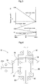
- Fig. 3 is a graph that shows the relationship among the speed change state of the continuously variable transmission device 18B, the speed range, and the rotation speed V of the output shaft 38 of the multi-stage power transmission section 19.
- the graph has a vertical axis indicative of the rotation speed V of the output shaft 38 and a horizontal axis indicative of the speed change state of the continuously variable transmission device 18B.
- the symbol “N” indicates the neutral state
- "+MAX” indicates the state of changing the speed to its maximum in the normal rotation direction
- -MAX indicates the state of changing the speed to its maximum in the reverse rotation direction.
- Engaging the first clutch CL1 and operating the continuously variable transmission device 18B causes motive power from the first output shaft 37a to be varied by a first-gear interlocking mechanism 39a and the first clutch CL1 and then outputted from the output shaft 38.
- the output shaft 38 has a rotational speed within a first-gear range. Varying the continuously variable transmission device 18B from "-MAX” to "+MAX” increases the rotation speed V of the output shaft 38 continuously from zero speed ("0") to the maximum speed within the first-gear range (“V1").
- Engaging the second clutch CL2 and operating the continuously variable transmission device 18B causes motive power from the third output shaft 37c to be varied by a second-gear interlocking mechanism 39b and the second clutch CL2 and then outputted from the output shaft 38.
- the output shaft 38 has a rotational speed within a second-gear range, which covers higher speeds than the first-gear range. Varying the continuously variable transmission device 18B from "+MAX" to "-MAX” increases the rotation speed V of the output shaft 38 continuously from the minimum speed within the second-gear range ("V1") to the maximum speed within the second-gear range ("V2").
- Engaging the third clutch CL3 and operating the continuously variable transmission device 18B causes motive power from the second output shaft 37b to be varied by a third-gear interlocking mechanism 39c and the third clutch CL3 and then outputted from the output shaft 38.
- the output shaft 38 has a rotational speed within a third-gear range, which covers higher speeds than the second-gear range. Varying the continuously variable transmission device 18B from "-MAX" to "+MAX” increases the rotation speed V of the output shaft 38 continuously from the minimum speed within the third-gear range ("V2") to the maximum speed within the third-gear range ("V3").
- Engaging the fourth clutch CL4 and operating the continuously variable transmission device 18B causes motive power from the third output shaft 37c to be varied by a fourth-gear interlocking mechanism 39d and the fourth clutch CL4 and then outputted from the output shaft 38.
- the output shaft 38 has a rotational speed within a fourth-gear range, which covers higher speeds than the third-gear range. Varying the continuously variable transmission device 18B from "+MAX" to "-MAX” increases the rotation speed V of the output shaft 38 continuously from the minimum speed within the fourth-gear range ("V3") to the maximum speed within the fourth-gear range ("V4").
- the forward/rearward travel switching device 20 includes (i) an input shaft 40 coupled to the output shaft 38 of the multi-stage power transmission section 19, (ii) a forward-travel clutch CLF and a rearward-travel clutch CLR both disposed on the input shaft 40, and (iii) an output shaft 42 coupled to the forward-travel clutch CLF with a forward-travel gear mechanism 41f in-between and to the rearward-travel clutch CLR with a rearward-travel gear mechanism 41r in-between.
- the rearward-travel gear mechanism 41r includes a reverse rotation gear 46 meshing with teeth on an output rotary member of the rearward-travel clutch CLR.
- the reverse rotation gear 46 is supported by the input shaft 22a of the rear-wheel differential mechanism 22 in such a manner as to be rotatable relative to the input shaft 22a.
- the forward/rearward travel switching device 20 is configured as follows: Engaging the forward-travel clutch CLF causes motive power transmitted from the multi-stage power transmission section 19 to the input shaft 40 to be converted by the forward-travel clutch CLF and the forward-travel gear mechanism 41f into forward-travel motive power and then outputted from the output shaft 42.
- Engaging the rearward-travel clutch CLR causes motive power transmitted from the multi-stage power transmission section 19 to the input shaft 40 to be converted by the rearward-travel clutch CLR and the rearward-travel gear mechanism 41r into rearward-travel motive power and then outputted from the output shaft 42.
- the output shaft 42 transmits the forward-travel motive power and the rearward-travel motive power to the rear-wheel gear interlocking mechanism 21, which then transmits them to the input shaft 22a of the rear-wheel differential mechanism 22.
- the front-wheel power transmission device 26 includes (i) an input shaft 43 coupled to the input shaft 22a of the rear-wheel differential mechanism 22 with the front-wheel gear interlocking mechanism 25 in-between, (ii) a constant-rate clutch CLT and a rate-increasing clutch CLH both disposed on the input shaft 43, and (iii) an output shaft 45 coupled to the constant-rate clutch CLT with a constant-rate gear mechanism 44a in-between and to the rate-increasing clutch CLH with a rate-increasing gear mechanism 44b in-between.
- the front-wheel power transmission device 26 is configured as follows: Engaging the constant-rate clutch CLT causes motive power transmitted from the input shaft 22a of the rear-wheel differential mechanism 22 to the input shaft 43 to be further transmitted through the constant-rate clutch CLT and the constant-rate gear mechanism 44a to the output shaft 45 and then to the front-wheel differential mechanism 28.
- Engaging the constant-rate clutch CLT causes motive power transmitted from the input shaft 22a of the rear-wheel differential mechanism 22 to the input shaft 43 to be further transmitted through the constant-rate clutch CLT and the constant-rate gear mechanism 44a to the output shaft 45 and then to the front-wheel differential mechanism 28.
- This achieves four-wheel drive with a constant rate for the front and rear wheels, that is, the tractor drives the front wheels 6 and the rear wheels 7 at respective average circumferential speeds substantially equal to each other.
- Engaging the rate-increasing clutch CLH causes motive power transmitted from the input shaft 22a of the rear-wheel differential mechanism 22 to the input shaft 43 to be further transmitted through the rate-increasing clutch CLH and the rate-increasing gear mechanism 44b to the output shaft 45 and then to the front-wheel differential mechanism 28.
- This achieves four-wheel drive with an increased rate for the front wheels, that is, the tractor drives the front wheels 6 at a first average circumferential speed and the rear wheels 7 at a second average circumferential speed, the first average circumferential speed being higher than the second average circumferential speed.
- the planetary gear device 18A includes two planetary gear sections 50 and 60 arranged in the front-back direction of the transmission case 3 (composite planetary gear device).
- the description below refers to the front one of the two planetary gear sections 50 and 60 as “first planetary gear section 50” and the back one thereof as “second planetary gear section 60".
- the first planetary gear section 50 includes (i) a first sun gear 51, (ii) a first planetary gear 52 meshing with the first sun gear 51, (iii) a first internally toothed gear 53 meshing with the first planetary gear 52, and (iv) a first carrier 54 that supports the first planetary gear 52 in such a manner that the first planetary gear 52 is rotatable and that is configured to rotate about the axis of the first sun gear 51 together with the first planetary gear 52 revolving about the first sun gear 51.
- the second planetary gear section 60 includes (i) a second sun gear 61, (ii) a second planetary gear 62 meshing with the second sun gear 61, (iv) a second internally toothed gear 63 meshing with the second planetary gear 62, and (iv) a second carrier 64 that supports the second planetary gear 62 in such a manner that the second planetary gear 62 is rotatable and that is configured to rotate about the axis of the second sun gear 61 together with the second planetary gear 62 revolving about the second sun gear 61.
- the first planetary gear section 50 includes a power transmission gear (not shown in the drawings) meshing with the first planetary gear 52.
- the planetary gear device 18A includes a coupling member (not shown in the drawings) extending from the first planetary gear section 50 to the second planetary gear section 60 and coupling the power transmission gear to the second planetary gear 62 in an interlocking manner.
- the first carrier 54 of the first planetary gear section 50 is coupled to the second carrier 64 of the second planetary gear section 60 in such a manner that the first carrier 54 and the second carrier 64 are rotatable integrally with each other.
- the second-gear interlocking mechanism 39b includes (i) an output power transmission gear 82 disposed on the third output shaft 37c and (ii) an input gear 82a disposed on an input member of the second clutch CL2 and meshing with the output power transmission gear 82.
- the second gear interlocking mechanism 35 includes a pump power transmission gear 86 disposed backward of the output power transmission gear 82 and coupled to the rotary shaft 31.
- the pump power transmission gear 86 is configured to take off motive power, which has been transmitted from the input shaft 17 to the rotary shaft 31, from the rotary shaft 31 and transmit the motive power to the hydraulic pump P.
- the first gear interlocking mechanism 34 includes (i) a first power transmission gear 70 disposed on the input shaft 17, (ii) a second power transmission gear 71 coupled to the first internally toothed gear 53, (iii) a first relay gear 72 meshing with the first power transmission gear 70, and (iv) a second relay gear 73 meshing with the second power transmission gear 71.
- the first gear interlocking mechanism 34 further includes a counter shaft 74 coupling the first relay gear 72 to the second relay gear 73 and supporting the first relay gear 72 and the second relay gear 73.
- the rear-wheel gear interlocking mechanism 21 includes a power transmission gear 91 meshing with the output gear 20a of the forward/rearward travel switching device 20 and configured to transmit motive power from the output gear 20a to the input shaft 22a of the rear-wheel differential mechanism 22.
- the power transmission gear 91 is supported by the input shaft 22a.
- the front-wheel gear interlocking mechanism 25 includes a first power transmission gear 77 disposed on the input shaft 22a of the rear-wheel differential mechanism 22 and a second power transmission gear 78 meshing with the first power transmission gear 77.
- the second power transmission gear 78 includes a shaft 78a below the input shaft 22a as the shaft of the first power transmission gear 77.
- the front-wheel gear interlocking mechanism 25 allows the output of the forward/rearward travel switching device 20 to be transmitted to the front-wheel power transmission device 26 as follows:
- the output gear 20a of the forward/rearward travel switching device 20 transmits motive power through the power transmission gear 91 and the input shaft 22a to the first power transmission gear 77, which then transmits the motive power through the second power transmission gear 78 and the shaft 78a to the input shaft 43 of the front-wheel power transmission device 26.
- the rear-wheel differential mechanism 22 is contained in the back case portion 3c of the transmission case 3.
- the rear-wheel differential mechanism 22 includes an input shaft 22a at a front portion and a differential case 93 at a back portion.
- the input shaft 22a is provided with a drive pinion 94.
- the differential case 93 has a lateral side portion provided with a ring gear 95 meshing with the drive pinion 94.
- the differential case 93 contains (i) a pair of differential pinions 96, (ii) a left side gear 97 meshing with the differential pinions 96 and configured to transmit motive power to the left rear wheel 7, and (iii) a right side gear 98 meshing with the differential pinions 96 and configured to transmit motive power to the right rear wheel 7.
- the differential case 93 has a lateral side portion provided with a differential lock device 99.
- the rear-wheel differential mechanism 22 is configured such that when it transmits forward-travel motive power to the rear wheels 7, the ring gear 95 rotates so that a lower portion 95a thereof rotates in the rotation direction R indicated with an arrow in Fig. 5 .
- the transmission case 3 is configured to store, in its internal space, lubricating oil for components such as the gear transmission 15M and the rear-wheel differential mechanism 22.
- the lubricating oil is preferably stored as illustrated in Fig. 5 to have a surface S at a level between the rotation axis X and lower end of the ring gear 95.
- the rear-wheel differential mechanism 22 is positioned such that the ring gear 95 has a lower portion 95a below the surface S of the lubricating oil.
- the rear-wheel differential mechanism 22 includes a gear cover 100 covering the lower portion 95a of the ring gear 95. While the ring gear 95 rotates, its lower portion 95a stirs the lubricating oil.
- the gear cover 100 serves to prevent such stirring from affecting the entire lubricating oil in the lubricating oil storage space in the transmission case.
- the gear cover 100 includes a front cover portion 101 and a lower cover portion 102.
- the front cover portion 101 faces and covers a front side face 95f of the lower portion 95a, the front side face 95f being that one of the opposite side faces of the ring gear 95 which is provided with teeth.
- the lower cover portion 102 extends from the lower end of the front cover portion 101 under the lower portion 95a to cover the lower portion 95a from below.
- the front cover portion 101 serves to prevent stirring of lubricating oil by the ring gear 95 from affecting that portion of the lubricating oil storage space which faces the front side face 95f.
- the lower cover portion 102 serves to prevent stirring of lubricating oil by the ring gear 95 from affecting that portion of the lubricating oil storage space which is under the ring gear 95.
- the gear cover 100 includes an upstream vertical cover portion 104 standing on that end of the lower cover portion 102 which is upstream of the lower portion 95a in the rotation direction R.
- the upstream vertical cover portion 104 is connected with that end of the front cover portion 101 which is upstream of the lower portion 95a in the rotation direction R.
- the gear cover 100 includes a downstream vertical cover portion 105 standing on that end of the lower cover portion 102 which is downstream of the lower portion 95a in the rotation direction R.
- the downstream vertical cover portion 105 is connected with that end of the front cover portion 101 which is downstream of the lower portion 95a in the rotation direction R.
- the gear cover 100 has a through hole 106 in that lower end portion of the front cover portion 101 which is downstream of the lower portion 95a in the rotation direction R.
- the through hole 106 allows lubricating oil to flow out.
- the lower portion 95a of the ring gear 95 forces lubricating oil between the lower portion 95a and the gear cover 100 downstream of the lower portion 95a in the rotation direction R.
- the through hole 106 allows the lubricating oil thus forced to flow out of the gear cover 100.
- the through hole 106 thereby prevents lubricating oil heated as a result of stirring by the ring gear 95 from stagnating between the gear cover 100 and the lower portion 95a.
- the gear cover 100 includes an upstream fixing portion 107 at that end which is upstream of the lower portion 95a in the rotation direction R and a downstream fixing portion 108 at that end which is downstream of the lower portion 95a in the rotation direction R.
- the upstream fixing portion 107 is coupled to a first support 109 of the transmission case 3 with use of a coupling bolt 110
- the downstream fixing portion 108 is coupled to a second support 111 of the transmission case 3 with use of a coupling bolt 112. This results in the gear cover 100 being detachably fixed to the transmission case 3.
- the present invention is applicable to power transmission devices for use in not only tractors but also various other work vehicles such as combines and multipurpose work vehicles.
Landscapes
- Engineering & Computer Science (AREA)
- General Engineering & Computer Science (AREA)
- Mechanical Engineering (AREA)
- General Details Of Gearings (AREA)
- Arrangement Of Transmissions (AREA)
- Arrangement And Driving Of Transmission Devices (AREA)
Abstract
Description
- The present invention relates to a power transmission device for a work vehicle.
- A power transmission device for a work vehicle may include a transmission case, a gear transmission contained in the transmission case and configured to receive motive power from a power source, and a differential mechanism contained in the transmission case and configured to receive motive power from the gear transmission and transmit the motive power to a left wheel and a right wheel.
-
Japanese Unexamined Patent Application Publication, Tokukai, No. 2019-95058 JP 2019-95058A - There has been a demand for a work vehicle capable of high-speed travel for efficient work. Power transmission devices of the above type are configured such that the transmission case stores lubricating oil inside and that the ring gear of the differential mechanism has a lower portion under the surface of the lubricating oil. Designing a work vehicle capable of traveling at a higher speed leads to the ring gear, whose lower portion is below the surface of lubricating oil, rotating and stirring the lubricating oil at a higher speed. This in turn poses a larger drive load on the ring gear, with the result of an increased loss of power during transmission through the differential mechanism.
- The present invention has an object of providing a power transmission device for a work vehicle that is capable of driving wheels at high speeds without increasing the loss of power during transmission through a differential mechanism caused by a ring gear being partially under the surface of lubricating oil.
- A power transmission device for a work vehicle according to the present invention includes: a transmission case; a gear transmission contained in the transmission case and configured to receive motive power from a power source; a differential mechanism contained in the transmission case and configured to receive motive power from the gear transmission and transmit the motive power to a left wheel and a right wheel; and a gear cover covering a lower portion of a ring gear of the differential mechanism.
- The above power transmission device is configured as follows: While the ring gear rotates, its lower portion stirs the lubricating oil. The gear cover serves to prevent such stirring from affecting the entire lubricating oil in the lubricating oil storage space in the transmission case. This allows the rotation speed of the ring gear to be increased without increasing the drive load on the ring gear, thereby making it possible to drive wheels at high speeds without increasing the loss of power during transmission through the differential mechanism.
- The power transmission device according to the present invention may preferably be arranged such that the gear cover includes: a front cover portion facing and covering a front side face of the lower portion, the front side face being a first side face of opposite side faces of the lower portion which first side face is provided with teeth; and a lower cover portion extending from a lower end of the front cover portion under the lower portion to cover the lower portion from below.
- The above power transmission device is configured as follows: The front cover portion prevents stirring of lubricating oil by the ring gear from affecting that portion of the lubricating oil storage space which faces the front side face of the ring gear. The lower cover portion prevents stirring of lubricating oil by the ring gear from affecting that portion of the lubricating oil storage space which is below the ring gear. This makes it possible to effectively prevent stirring of lubricating oil by the ring gear from affecting the entire lubricating oil in the lubricating oil storage space, thereby making it possible to drive wheels at higher speeds without increasing the loss of power during transmission through the differential mechanism.
- The power transmission device according to the present invention may preferably be arranged such that the gear cover has a through hole that is in a lower end portion of the front cover portion which lower end portion is downstream of the lower portion in a direction in which the ring gear rotates and that allows lubricating oil to flow out.
- The above power transmission device is configured as follows: The lower portion of the ring gear forces lubricating oil between the lower portion and the gear cover downstream of the lower portion in the rotation direction. The through hole allows the lubricating oil thus forced to flow out of the gear cover. The through hole thereby prevents lubricating oil heated as a result of stirring by the ring gear from stagnating between the gear cover and the lower portion. This prevents a rise in the temperature of lubricating oil between the gear cover and the lower portion.
- The power transmission device according to the present invention may preferably be arranged such that the gear cover includes: an upstream fixing portion fixing to the transmission case a first end of the gear cover which first end is upstream of the lower portion in a direction in which the ring gear rotates; and a downstream fixing portion fixing to the transmission case a second end of the gear cover which second end is downstream of the lower portion in the direction in which the ring gear rotates.
- The above power transmission device is configured as follows: The upstream fixing portion fixes to the transmission case that end of the gear cover which is upstream of the lower portion in the rotation direction. The downstream fixing portion fixes to the transmission case that end of the gear cover which is downstream of the lower portion in the rotation direction. This allows the gear cover to be fixed to the transmission case firmly against the oil pressure applied to the gear cover by stirring of lubricating oil by the ring gear.
- The power transmission device according to the present invention may preferably be arranged such that the gear cover includes: a front cover portion facing and covering a front side face of the lower portion, the front side face being a first side face of opposite side faces of the lower portion which first side face is provided with teeth; a lower cover portion extending from a lower end of the front cover portion under the lower portion to cover the lower portion from below; and a reverse cover portion standing on an end of the lower cover portion which end is opposite to the front cover portion and facing and covering a reverse side face of the lower portion, the reverse side face being a second side face of the opposite side faces of the lower portion which second side face is not provided with teeth.
- The above power transmission device is configured as follows: The front cover portion prevents stirring of lubricating oil by the ring gear from affecting that portion of the lubricating oil storage space which faces the front side face of the ring gear. The lower cover portion prevents stirring of lubricating oil by the ring gear from affecting that portion of the lubricating oil storage space which is below the ring gear. The reverse cover portion prevents stirring of lubricating oil by the ring gear from affecting that portion of the lubricating oil storage space which faces the reverse side face of the ring gear. This makes it possible to effectively prevent stirring of lubricating oil by the ring gear from affecting the entire lubricating oil in the lubricating oil storage space, thereby making it possible to drive wheels at higher speeds without increasing the loss of power during transmission through the differential mechanism.
-
-
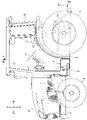
Fig. 1 is a left side view of a tractor in its entirety. -
Fig. 2 is a diagram illustrating a power transmission device. -
Fig. 3 is a graph that shows the relationship among the speed change state of a continuously variable transmission device, the speed range, and the rotation speed of the output shaft of a multi-stage power transmission section. -
Fig. 4 is a diagram schematically illustrating a rear-wheel differential mechanism. -
Fig. 5 is a side view of a rear-wheel differential mechanism. -
Fig. 6 is a plan view of a rear-wheel differential mechanism. -
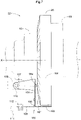
Fig. 7 is a cross-sectional view of the rear-wheel differential mechanism taken along line VII-VII inFig. 5 . -
Fig. 8 is a perspective view of a gear cover. -
Fig. 9 is a cross-sectional view of a gear cover for an alternative embodiment. - The description below deals with an example embodiment of the present invention with reference to drawings.
- The embodiment described below is for a tractor (which is an example of the "work vehicle") including a body.
Fig. 1 shows arrow F to indicate the forward direction of the body, arrow B to indicate the backward direction of the body, arrow U to indicate the upward direction of the body, and arrow D to indicate the downward direction of the body. The front side of the drawing corresponds to the leftward direction of the body, whereas the back side of the drawing corresponds to the rightward direction of the body. - The body of the tractor includes (i) a
body frame 5 including components such as anengine 1, (ii) a pair of left and right drivablefront wheels 6 disposed at a front portion of thebody frame 5 and serving as travel devices, and (iii) a pair of left and right drivablerear wheels 7 disposed at a back portion of thebody frame 5 and serving as travel devices. Thebody frame 5 includes anengine 1, aclutch housing 2 behind theengine 1, atransmission case 3 coupled to theclutch housing 2, and a front frame portion 4. Thefront wheels 6 are swingable about an axis extending in the up-down direction of the body (not shown in the drawings) to be turned. The body includes at a front portion a motor section 8 containing theengine 1, and also includes a driver section 9 at a back portion. The driver section 9 includes a driver'sseat 10, asteering wheel 11 for use to turn thefront wheels 6, and acabin 12 defining a driver space. Thebody frame 5 has a back portion provided with alink mechanism 13 and a power take-off shaft 14. Thelink mechanism 13 allows any of various work devices such as a rotary tiller device (not shown in the drawings) to be coupled to thebody frame 5 in such a manner as to be capable of being lifted and lowered. The power take-off shaft 14 takes off motive power from theengine 1 and transmits the motive power to a work device coupled to thebody frame 5. - The tractor includes a
power transmission device 15 illustrated inFig. 2 . Thepower transmission device 15 transmits motive power from theengine 1 to thefront wheels 6 and therear wheels 7. Thetransmission case 3 is included in thepower transmission device 15 in such an orientation as to have a front-back direction identical to that of the body. - As illustrated in
Fig. 2 , thepower transmission device 15 includes atransmission case 3 that contains agear transmission 15M, a rear-wheeldifferential mechanism 22, and a front-wheelpower transmission device 26. Thegear transmission 15M includes (i) amain transmission section 18 coupled to theinput shaft 17 of thetransmission case 3, (ii) a multi-stagepower transmission section 19 configured to receive the output of themain transmission section 18, (iii) a forward/rearwardtravel switching device 20 configured to receive the output of the multi-stagepower transmission section 19, (iv) a rear-wheelgear interlocking mechanism 21 configured to transmit the output of the forward/rearwardtravel switching device 20 to the rear-wheeldifferential mechanism 22, and (v) a front-wheelgear interlocking mechanism 25 configured to transmit the output of the forward/rearwardtravel switching device 20 to the front-wheelpower transmission device 26. - The
transmission case 3 includes afront case portion 3a, amiddle case portion 3b, and aback case portion 3c as segmented in the front-back direction of thetransmission case 3. Thefront case portion 3a contains themain transmission section 18, the multi-stagepower transmission section 19, and the front-wheelpower transmission device 26. Themiddle case portion 3b contains the rear-wheelgear interlocking mechanism 21 and the front-wheelgear interlocking mechanism 25. Theback case portion 3c contains the forward/rearwardtravel switching device 20 and the rear-wheel differential mechanism 22. - The
main transmission section 18 includes aplanetary gear device 18A and a continuouslyvariable transmission device 18B. Theplanetary gear device 18A has a front portion coupled to a firstgear interlocking mechanism 34 configured to allow motive power from theinput shaft 17 to be received by theplanetary gear device 18A. The continuouslyvariable transmission device 18B has a back portion coupled to a secondgear interlocking mechanism 35 configured to allow motive power from theinput shaft 17 to be received by the continuouslyvariable transmission device 18B. The continuouslyvariable transmission device 18B has a front portion coupled to a thirdgear interlocking mechanism 36 configured to allow the output of the continuouslyvariable transmission device 18B to be received by theplanetary gear device 18A. The forward/rearwardtravel switching device 20 has a front portion coupled to the rear-wheelgear interlocking mechanism 21, which is configured to transmit the output of the forward/rearwardtravel switching device 20 to the rear-wheel differential mechanism 22. The front-wheelpower transmission device 26 has a back portion coupled to the front-wheelgear interlocking mechanism 25, which is configured to transmit the output of the forward/rearwardtravel switching device 20 to the front-wheelpower transmission device 26. - As illustrated in
Fig. 2 , thepower transmission device 15 is configured as follows: Motive power outputted by theengine 1 from itsoutput shaft 1a is transmitted through a main clutch 16 to theinput shaft 17 of thetransmission case 3; theinput shaft 17 transmits its motive power to themain transmission section 18; themain transmission section 18 outputs its motive power to the multi-stagepower transmission section 19; the multi-stagepower transmission section 19 outputs its motive power to the forward/rearwardtravel switching device 20; and the forward/rearwardtravel switching device 20 outputs its motive power through the rear-wheelgear interlocking mechanism 21 to theinput shaft 22a of the rear-wheel differential mechanism 22. Thepower transmission device 15 includes a pair ofsteering brakes 23 and a pair ofdeceleration mechanisms 24 as a power transmission system for transmitting the output of the rear-wheel differential mechanism 22 to the respectiverear wheels 7. Thedeceleration mechanisms 24 are each in the form of a planetary gear mechanism. Thepower transmission device 15 includes arotary shaft 27 and a front-wheel differential mechanism 28. The front-wheelgear interlocking mechanism 25 transmits motive power from theinput shaft 22a of the rear-wheel differential mechanism 22 to the front-wheelpower transmission device 26, which then transmits the motive power through therotary shaft 27 to the front-wheel differential mechanism 28. The front-wheelgear interlocking mechanism 25 is provided with aparking brake 29. - As illustrated in
Fig. 2 , thepower transmission device 15 includes awork transmission device 30. Thework transmission device 30 receives motive power from theinput shaft 17 through therotary shaft 31 and a rearrotary shaft 32, varies the motive power, and transmits the resulting motive power to the power take-offshaft 14. - The
main transmission section 18, as illustrated inFig. 2 , includes aplanetary gear device 18A and a continuouslyvariable transmission device 18B. Theplanetary gear device 18A includes twoplanetary gear sections transmission case 3. The forward one of the twoplanetary gear sections planetary gear section 50, is coupled to theinput shaft 17 with the firstgear interlocking mechanism 34 in-between. The continuouslyvariable transmission device 18B is of a hydrostatic type, and includes a hydraulic pump P with a variable capacity and a hydraulic motor M. The continuouslyvariable transmission device 18B includes a pump shaft coupled to theinput shaft 17 with the secondgear interlocking mechanism 35 and therotary shaft 31 in-between. The continuouslyvariable transmission device 18B includes a motor shaft coupled to theplanetary gear section 50 with the thirdgear interlocking mechanism 36 in-between. - The
main transmission section 18 is configured as follows: The continuouslyvariable transmission device 18B varies motive power from theengine 1. Theplanetary gear device 18A receives the varied motive power and motive power transmitted from theengine 1 through the thirdgear interlocking mechanism 36. Theplanetary gear sections planetary gear device 18A allows the composite motive power to be outputted from afirst output shaft 37a, asecond output shaft 37b, and athird output shaft 37c, which coaxially overlap with one another. - The multi-stage
power transmission section 19, as illustrated inFig. 2 , includes anoutput shaft 38 and first to fourth clutches CL1 to CL4 disposed on theoutput shaft 38 for respective stages and each configured to receive the output of theplanetary gear device 18A. - The multi-stage
power transmission section 19 is configured such that appropriately operating the continuouslyvariable transmission device 18B and the four clutches CL1 to CL4 allows the composite motive power from theplanetary gear device 18A to be outputted from theoutput shaft 38 in one of four speed ranges. -
Fig. 3 is a graph that shows the relationship among the speed change state of the continuouslyvariable transmission device 18B, the speed range, and the rotation speed V of theoutput shaft 38 of the multi-stagepower transmission section 19. The graph has a vertical axis indicative of the rotation speed V of theoutput shaft 38 and a horizontal axis indicative of the speed change state of the continuouslyvariable transmission device 18B. The symbol "N" indicates the neutral state, "+MAX" indicates the state of changing the speed to its maximum in the normal rotation direction, and "-MAX" indicates the state of changing the speed to its maximum in the reverse rotation direction. - Engaging the first clutch CL1 and operating the continuously
variable transmission device 18B causes motive power from thefirst output shaft 37a to be varied by a first-gear interlocking mechanism 39a and the first clutch CL1 and then outputted from theoutput shaft 38. As illustrated inFig. 3 , theoutput shaft 38 has a rotational speed within a first-gear range. Varying the continuouslyvariable transmission device 18B from "-MAX" to "+MAX" increases the rotation speed V of theoutput shaft 38 continuously from zero speed ("0") to the maximum speed within the first-gear range ("V1"). - Engaging the second clutch CL2 and operating the continuously
variable transmission device 18B causes motive power from thethird output shaft 37c to be varied by a second-gear interlocking mechanism 39b and the second clutch CL2 and then outputted from theoutput shaft 38. As illustrated inFig. 3 , theoutput shaft 38 has a rotational speed within a second-gear range, which covers higher speeds than the first-gear range. Varying the continuouslyvariable transmission device 18B from "+MAX" to "-MAX" increases the rotation speed V of theoutput shaft 38 continuously from the minimum speed within the second-gear range ("V1") to the maximum speed within the second-gear range ("V2"). - Engaging the third clutch CL3 and operating the continuously
variable transmission device 18B causes motive power from thesecond output shaft 37b to be varied by a third-gear interlocking mechanism 39c and the third clutch CL3 and then outputted from theoutput shaft 38. As illustrated inFig. 3 , theoutput shaft 38 has a rotational speed within a third-gear range, which covers higher speeds than the second-gear range. Varying the continuouslyvariable transmission device 18B from "-MAX" to "+MAX" increases the rotation speed V of theoutput shaft 38 continuously from the minimum speed within the third-gear range ("V2") to the maximum speed within the third-gear range ("V3"). - Engaging the fourth clutch CL4 and operating the continuously
variable transmission device 18B causes motive power from thethird output shaft 37c to be varied by a fourth-gear interlocking mechanism 39d and the fourth clutch CL4 and then outputted from theoutput shaft 38. As illustrated inFig. 3 , theoutput shaft 38 has a rotational speed within a fourth-gear range, which covers higher speeds than the third-gear range. Varying the continuouslyvariable transmission device 18B from "+MAX" to "-MAX" increases the rotation speed V of theoutput shaft 38 continuously from the minimum speed within the fourth-gear range ("V3") to the maximum speed within the fourth-gear range ("V4"). - The forward/rearward
travel switching device 20, as illustrated inFig. 2 , includes (i) aninput shaft 40 coupled to theoutput shaft 38 of the multi-stagepower transmission section 19, (ii) a forward-travel clutch CLF and a rearward-travel clutch CLR both disposed on theinput shaft 40, and (iii) anoutput shaft 42 coupled to the forward-travel clutch CLF with a forward-travel gear mechanism 41f in-between and to the rearward-travel clutch CLR with a rearward-travel gear mechanism 41r in-between. As illustrated inFig. 2 , the rearward-travel gear mechanism 41r includes areverse rotation gear 46 meshing with teeth on an output rotary member of the rearward-travel clutch CLR. Thereverse rotation gear 46 is supported by theinput shaft 22a of the rear-wheel differential mechanism 22 in such a manner as to be rotatable relative to theinput shaft 22a. - The forward/rearward
travel switching device 20 is configured as follows: Engaging the forward-travel clutch CLF causes motive power transmitted from the multi-stagepower transmission section 19 to theinput shaft 40 to be converted by the forward-travel clutch CLF and the forward-travel gear mechanism 41f into forward-travel motive power and then outputted from theoutput shaft 42. Engaging the rearward-travel clutch CLR causes motive power transmitted from the multi-stagepower transmission section 19 to theinput shaft 40 to be converted by the rearward-travel clutch CLR and the rearward-travel gear mechanism 41r into rearward-travel motive power and then outputted from theoutput shaft 42. Theoutput shaft 42 transmits the forward-travel motive power and the rearward-travel motive power to the rear-wheelgear interlocking mechanism 21, which then transmits them to theinput shaft 22a of the rear-wheel differential mechanism 22. - The front-wheel
power transmission device 26, as illustrated inFig. 2 , includes (i) aninput shaft 43 coupled to theinput shaft 22a of the rear-wheel differential mechanism 22 with the front-wheelgear interlocking mechanism 25 in-between, (ii) a constant-rate clutch CLT and a rate-increasing clutch CLH both disposed on theinput shaft 43, and (iii) anoutput shaft 45 coupled to the constant-rate clutch CLT with a constant-rate gear mechanism 44a in-between and to the rate-increasing clutch CLH with a rate-increasinggear mechanism 44b in-between. - The front-wheel
power transmission device 26 is configured as follows: Engaging the constant-rate clutch CLT causes motive power transmitted from theinput shaft 22a of the rear-wheel differential mechanism 22 to theinput shaft 43 to be further transmitted through the constant-rate clutch CLT and the constant-rate gear mechanism 44a to theoutput shaft 45 and then to the front-wheel differential mechanism 28. This achieves four-wheel drive with a constant rate for the front and rear wheels, that is, the tractor drives thefront wheels 6 and therear wheels 7 at respective average circumferential speeds substantially equal to each other. Engaging the rate-increasing clutch CLH causes motive power transmitted from theinput shaft 22a of the rear-wheel differential mechanism 22 to theinput shaft 43 to be further transmitted through the rate-increasing clutch CLH and the rate-increasinggear mechanism 44b to theoutput shaft 45 and then to the front-wheel differential mechanism 28. This achieves four-wheel drive with an increased rate for the front wheels, that is, the tractor drives thefront wheels 6 at a first average circumferential speed and therear wheels 7 at a second average circumferential speed, the first average circumferential speed being higher than the second average circumferential speed. - The
planetary gear device 18A, as illustrated inFig. 2 , includes twoplanetary gear sections planetary gear sections planetary gear section 50" and the back one thereof as "secondplanetary gear section 60". - The first
planetary gear section 50, as illustrated inFig. 2 , includes (i) afirst sun gear 51, (ii) a firstplanetary gear 52 meshing with thefirst sun gear 51, (iii) a first internally toothedgear 53 meshing with the firstplanetary gear 52, and (iv) a first carrier 54 that supports the firstplanetary gear 52 in such a manner that the firstplanetary gear 52 is rotatable and that is configured to rotate about the axis of thefirst sun gear 51 together with the firstplanetary gear 52 revolving about thefirst sun gear 51. - The second
planetary gear section 60, as illustrated inFig. 2 , includes (i) asecond sun gear 61, (ii) a secondplanetary gear 62 meshing with thesecond sun gear 61, (iv) a second internally toothedgear 63 meshing with the secondplanetary gear 62, and (iv) a second carrier 64 that supports the secondplanetary gear 62 in such a manner that the secondplanetary gear 62 is rotatable and that is configured to rotate about the axis of thesecond sun gear 61 together with the secondplanetary gear 62 revolving about thesecond sun gear 61. - The first
planetary gear section 50 includes a power transmission gear (not shown in the drawings) meshing with the firstplanetary gear 52. Theplanetary gear device 18A includes a coupling member (not shown in the drawings) extending from the firstplanetary gear section 50 to the secondplanetary gear section 60 and coupling the power transmission gear to the secondplanetary gear 62 in an interlocking manner. The first carrier 54 of the firstplanetary gear section 50 is coupled to the second carrier 64 of the secondplanetary gear section 60 in such a manner that the first carrier 54 and the second carrier 64 are rotatable integrally with each other. - As illustrated in
Fig. 2 , the second-gear interlocking mechanism 39b includes (i) an outputpower transmission gear 82 disposed on thethird output shaft 37c and (ii) aninput gear 82a disposed on an input member of the second clutch CL2 and meshing with the outputpower transmission gear 82. - As illustrated in
Fig. 2 , the secondgear interlocking mechanism 35 includes a pumppower transmission gear 86 disposed backward of the outputpower transmission gear 82 and coupled to therotary shaft 31. The pumppower transmission gear 86 is configured to take off motive power, which has been transmitted from theinput shaft 17 to therotary shaft 31, from therotary shaft 31 and transmit the motive power to the hydraulic pump P. - The first
gear interlocking mechanism 34, as illustrated inFig. 2 , includes (i) a firstpower transmission gear 70 disposed on theinput shaft 17, (ii) a secondpower transmission gear 71 coupled to the first internally toothedgear 53, (iii) afirst relay gear 72 meshing with the firstpower transmission gear 70, and (iv) asecond relay gear 73 meshing with the secondpower transmission gear 71. The firstgear interlocking mechanism 34 further includes acounter shaft 74 coupling thefirst relay gear 72 to thesecond relay gear 73 and supporting thefirst relay gear 72 and thesecond relay gear 73. - As illustrated in
Fig. 2 , the rear-wheelgear interlocking mechanism 21 includes apower transmission gear 91 meshing with theoutput gear 20a of the forward/rearwardtravel switching device 20 and configured to transmit motive power from theoutput gear 20a to theinput shaft 22a of the rear-wheel differential mechanism 22. Thepower transmission gear 91 is supported by theinput shaft 22a. - As illustrated in
Fig. 2 , the front-wheelgear interlocking mechanism 25 includes a firstpower transmission gear 77 disposed on theinput shaft 22a of the rear-wheel differential mechanism 22 and a secondpower transmission gear 78 meshing with the firstpower transmission gear 77. The secondpower transmission gear 78 includes ashaft 78a below theinput shaft 22a as the shaft of the firstpower transmission gear 77. - The front-wheel
gear interlocking mechanism 25 allows the output of the forward/rearwardtravel switching device 20 to be transmitted to the front-wheelpower transmission device 26 as follows: Theoutput gear 20a of the forward/rearwardtravel switching device 20 transmits motive power through thepower transmission gear 91 and theinput shaft 22a to the firstpower transmission gear 77, which then transmits the motive power through the secondpower transmission gear 78 and theshaft 78a to theinput shaft 43 of the front-wheelpower transmission device 26. - As illustrated in
Fig. 2 , the rear-wheel differential mechanism 22 is contained in theback case portion 3c of thetransmission case 3. As illustrated inFig. 4 , the rear-wheel differential mechanism 22 includes aninput shaft 22a at a front portion and adifferential case 93 at a back portion. Theinput shaft 22a is provided with adrive pinion 94. Thedifferential case 93 has a lateral side portion provided with aring gear 95 meshing with thedrive pinion 94. Thedifferential case 93 contains (i) a pair ofdifferential pinions 96, (ii) aleft side gear 97 meshing with thedifferential pinions 96 and configured to transmit motive power to the leftrear wheel 7, and (iii) aright side gear 98 meshing with thedifferential pinions 96 and configured to transmit motive power to the rightrear wheel 7. Thedifferential case 93 has a lateral side portion provided with adifferential lock device 99. - The rear-
wheel differential mechanism 22 is configured such that when it transmits forward-travel motive power to therear wheels 7, thering gear 95 rotates so that alower portion 95a thereof rotates in the rotation direction R indicated with an arrow inFig. 5 . - The
transmission case 3 is configured to store, in its internal space, lubricating oil for components such as thegear transmission 15M and the rear-wheel differential mechanism 22. The lubricating oil is preferably stored as illustrated inFig. 5 to have a surface S at a level between the rotation axis X and lower end of thering gear 95. The rear-wheel differential mechanism 22 is positioned such that thering gear 95 has alower portion 95a below the surface S of the lubricating oil. - As illustrated in
Figs. 5 to 7 , the rear-wheel differential mechanism 22 includes agear cover 100 covering thelower portion 95a of thering gear 95. While thering gear 95 rotates, itslower portion 95a stirs the lubricating oil. Thegear cover 100 serves to prevent such stirring from affecting the entire lubricating oil in the lubricating oil storage space in the transmission case. - The
gear cover 100, as illustrated inFigs. 5 to 8 , includes afront cover portion 101 and alower cover portion 102. Thefront cover portion 101 faces and covers afront side face 95f of thelower portion 95a, thefront side face 95f being that one of the opposite side faces of thering gear 95 which is provided with teeth. Thelower cover portion 102 extends from the lower end of thefront cover portion 101 under thelower portion 95a to cover thelower portion 95a from below. Thefront cover portion 101 serves to prevent stirring of lubricating oil by thering gear 95 from affecting that portion of the lubricating oil storage space which faces thefront side face 95f. Thelower cover portion 102 serves to prevent stirring of lubricating oil by thering gear 95 from affecting that portion of the lubricating oil storage space which is under thering gear 95. - As illustrated in
Figs. 5 ,6 , and8 , thegear cover 100 includes an upstreamvertical cover portion 104 standing on that end of thelower cover portion 102 which is upstream of thelower portion 95a in the rotation direction R. The upstreamvertical cover portion 104 is connected with that end of thefront cover portion 101 which is upstream of thelower portion 95a in the rotation direction R. Thegear cover 100 includes a downstreamvertical cover portion 105 standing on that end of thelower cover portion 102 which is downstream of thelower portion 95a in the rotation direction R. The downstreamvertical cover portion 105 is connected with that end of thefront cover portion 101 which is downstream of thelower portion 95a in the rotation direction R. - As illustrated in
Figs. 5 ,7 , and8 , thegear cover 100 has a throughhole 106 in that lower end portion of thefront cover portion 101 which is downstream of thelower portion 95a in the rotation direction R. The throughhole 106 allows lubricating oil to flow out. Thelower portion 95a of thering gear 95 forces lubricating oil between thelower portion 95a and thegear cover 100 downstream of thelower portion 95a in the rotation direction R. The throughhole 106 allows the lubricating oil thus forced to flow out of thegear cover 100. The throughhole 106 thereby prevents lubricating oil heated as a result of stirring by thering gear 95 from stagnating between thegear cover 100 and thelower portion 95a. - The
gear cover 100, as illustrated inFig. 8 , includes anupstream fixing portion 107 at that end which is upstream of thelower portion 95a in the rotation direction R and adownstream fixing portion 108 at that end which is downstream of thelower portion 95a in the rotation direction R. As illustrated inFigs. 5 to 7 , theupstream fixing portion 107 is coupled to afirst support 109 of thetransmission case 3 with use of acoupling bolt 110, and the downstream fixingportion 108 is coupled to asecond support 111 of thetransmission case 3 with use of acoupling bolt 112. This results in thegear cover 100 being detachably fixed to thetransmission case 3. -
- (1)
Fig. 9 is a vertical cross section of agear cover 100A for an alternative embodiment. As illustrated inFig. 9 , thegear cover 100A includes areverse cover portion 103 in addition to thefront cover portion 101 and thelower cover portion 102. Thereverse cover portion 103 stands on that end of thelower cover portion 102 which is opposite to thefront cover portion 101. Thereverse cover portion 103 faces and covers areverse side face 95r of thelower portion 95a, thereverse side face 95r being that one of the opposite side faces of thering gear 95 which is provided with no teeth. Thereverse cover portion 103 serves to prevent stirring of lubricating oil by thering gear 95 from affecting that portion of the lubricating oil storage space which faces thereverse side face 95r. - (2) The embodiment described above is an example including an upstream
vertical cover portion 104 and a downstreamvertical cover portion 105. Thegear cover 100 may alternatively not include an upstreamvertical cover portion 104 or a downstreamvertical cover portion 105. - (3) The embodiment described above is an example with a through
hole 106. Thegear cover 100 may alternatively not have a throughhole 106. - (4) The embodiment described above is an example in which the
gear cover 100 is provided for the rear-wheel differential mechanism 22. The embodiment may be altered such that the front-wheel differential mechanism 28 is contained in thetransmission case 3 and provided with a gear cover. - (5) The embodiment described above is an example including an
engine 1 as a power source configured to supply motive power to thegear transmission 15M. The power source may alternatively be an electric motor instead of an engine, or a combination of an engine and an electric motor. - The present invention is applicable to power transmission devices for use in not only tractors but also various other work vehicles such as combines and multipurpose work vehicles.
Claims (5)
- A power transmission device (15) for a work vehicle,
the power transmission device (15) comprising:a transmission case (3);a gear transmission (15M) contained in the transmission case (3) and configured to receive motive power from a power source (1);a differential mechanism (22) contained in the transmission case (3) and configured to receive motive power from the gear transmission (15M) and transmit the motive power to a left wheel and a right wheel; anda gear cover (100) covering a lower portion (95a) of a ring gear (95) of the differential mechanism (22). - The power transmission device (15) according to claim 1, wherein
the gear cover (100) includes:a front cover portion (101) facing and covering a front side face (95f) of the lower portion(95a), the front side face(95f) being a first side face of opposite side faces of the lower portion (95a) which first side face is provided with teeth; anda lower cover portion (102) extending from a lower end of the front cover portion (101) under the lower portion (95a) to cover the lower portion (95a) from below. - The power transmission device (15) according to claim 2, wherein
the gear cover (100) has a through hole (106) that is in a lower end portion of the front cover portion (101) which lower end portion is downstream of the lower portion (95a) in a direction in which the ring gear (95) rotates and that allows lubricating oil to flow out. - The power transmission device (15) according to any one of claims 1 to 3, wherein
the gear cover (100) includes:an upstream fixing portion (107) fixing to the transmission case (3) a first end of the gear cover (100) which first end is upstream of the lower portion (95a) in a direction in which the ring gear (95) rotates; anda downstream fixing portion (108) fixing to the transmission case (3) a second end of the gear cover (100) which second end is downstream of the lower portion (95a) in the direction in which the ring gear (95) rotates. - The power transmission device (15) according to claim 2, taken in combination with any one of claims 1 to 4, wherein
the gear cover (100) further includes a reverse cover portion (103) standing on an end of the lower cover portion (102) which end is opposite to the front cover portion (101) and facing and covering a reverse side face (95r) of the lower portion (95a), the reverse side face (95r) being a second side face of the opposite side faces of the lower portion (95a) which second side face is not provided with teeth.
Applications Claiming Priority (1)
| Application Number | Priority Date | Filing Date | Title |
|---|---|---|---|
| JP2021099697A JP7504060B2 (en) | 2021-06-15 | 2021-06-15 | Power transmission device for work vehicles |
Publications (2)
| Publication Number | Publication Date |
|---|---|
| EP4105521A1 true EP4105521A1 (en) | 2022-12-21 |
| EP4105521B1 EP4105521B1 (en) | 2025-04-09 |
Family
ID=81940718
Family Applications (1)
| Application Number | Title | Priority Date | Filing Date |
|---|---|---|---|
| EP22177323.7A Active EP4105521B1 (en) | 2021-06-15 | 2022-06-03 | Power transmission device for work vehicle |
Country Status (3)
| Country | Link |
|---|---|
| US (1) | US12072014B2 (en) |
| EP (1) | EP4105521B1 (en) |
| JP (1) | JP7504060B2 (en) |
Families Citing this family (3)
| Publication number | Priority date | Publication date | Assignee | Title |
|---|---|---|---|---|
| JP7717029B2 (en) * | 2022-06-21 | 2025-08-01 | 株式会社クボタ | Work vehicle |
| JP7797318B2 (en) * | 2022-06-24 | 2026-01-13 | 株式会社クボタ | Work vehicle |
| CN121088794A (en) * | 2025-11-06 | 2025-12-09 | 山东博峻智能科技有限公司 | Automatic gear shifting structure of gearbox of electric loader |
Citations (5)
| Publication number | Priority date | Publication date | Assignee | Title |
|---|---|---|---|---|
| US5050447A (en) * | 1988-08-11 | 1991-09-24 | Aisin Aw Co., Ltd. | Oil reservoir device for an automatic transmission |
| US20160377164A1 (en) * | 2015-06-23 | 2016-12-29 | Ford Global Technologies, Llc | Differential and differential lubricating fluid management system |
| US9810311B1 (en) * | 2016-08-16 | 2017-11-07 | Ford Global Technologies, Inc. | Baffle for lubrication management in an axle assembly |
| JP2019095058A (en) | 2017-11-24 | 2019-06-20 | 株式会社クボタ | Tractor gear change transmission device and tractor |
| WO2019177882A1 (en) * | 2018-03-14 | 2019-09-19 | Dana Heavy Vehicle Systems Group, Llc | A lubricant fluid shroud |
Family Cites Families (9)
| Publication number | Priority date | Publication date | Assignee | Title |
|---|---|---|---|---|
| US4662241A (en) * | 1985-04-03 | 1987-05-05 | The J. B. Foote Foundry Co. | Two-shaft gear drive |
| JP2560305B2 (en) | 1987-01-23 | 1996-12-04 | トヨタ自動車株式会社 | Backlash shim selection method |
| US5289738A (en) * | 1992-06-08 | 1994-03-01 | Eaton Corporation | Hydrostatic transaxle assembly and improved coupling arrangement therefor |
| JP3084940B2 (en) | 1992-06-25 | 2000-09-04 | ソニー株式会社 | Digital broadcast receiver |
| US20070044587A1 (en) * | 2005-08-29 | 2007-03-01 | Shine Far Metal Industry Co., Ltd. | Driving device for differential |
| JP4936947B2 (en) | 2007-03-26 | 2012-05-23 | 株式会社小松製作所 | Axle device |
| US8733528B1 (en) * | 2011-01-13 | 2014-05-27 | David J. Goerend | Transmission with continuous clutch lubrication |
| WO2019102999A1 (en) | 2017-11-24 | 2019-05-31 | 株式会社クボタ | Tractor variable speed transmission device and tractor |
| JP6995441B2 (en) | 2018-03-05 | 2022-01-14 | ジヤトコ株式会社 | Power transmission device |
-
2021
- 2021-06-15 JP JP2021099697A patent/JP7504060B2/en active Active
-
2022
- 2022-06-03 EP EP22177323.7A patent/EP4105521B1/en active Active
- 2022-06-06 US US17/832,855 patent/US12072014B2/en active Active
Patent Citations (5)
| Publication number | Priority date | Publication date | Assignee | Title |
|---|---|---|---|---|
| US5050447A (en) * | 1988-08-11 | 1991-09-24 | Aisin Aw Co., Ltd. | Oil reservoir device for an automatic transmission |
| US20160377164A1 (en) * | 2015-06-23 | 2016-12-29 | Ford Global Technologies, Llc | Differential and differential lubricating fluid management system |
| US9810311B1 (en) * | 2016-08-16 | 2017-11-07 | Ford Global Technologies, Inc. | Baffle for lubrication management in an axle assembly |
| JP2019095058A (en) | 2017-11-24 | 2019-06-20 | 株式会社クボタ | Tractor gear change transmission device and tractor |
| WO2019177882A1 (en) * | 2018-03-14 | 2019-09-19 | Dana Heavy Vehicle Systems Group, Llc | A lubricant fluid shroud |
Also Published As
| Publication number | Publication date |
|---|---|
| JP7504060B2 (en) | 2024-06-21 |
| EP4105521B1 (en) | 2025-04-09 |
| JP2022191071A (en) | 2022-12-27 |
| US20220397189A1 (en) | 2022-12-15 |
| US12072014B2 (en) | 2024-08-27 |
Similar Documents
| Publication | Publication Date | Title |
|---|---|---|
| EP4105521B1 (en) | Power transmission device for work vehicle | |
| EP3085992B1 (en) | Transmission apparatus | |
| US8657713B2 (en) | Power train for work vehicle | |
| US4357840A (en) | Multi-speed planetary differential | |
| US6478706B1 (en) | Planetary steering differential | |
| CN101809332A (en) | Hydrostatic mechanical power-split transmission | |
| EP3798468B1 (en) | Traveling transmission device of tractor | |
| EP4019809B1 (en) | Power transmission device for work vehicle | |
| US5685389A (en) | Drive of a cross-country vehicle | |
| EP0025499A2 (en) | Differential for multiplying torquing force and drive train | |
| JP7390987B2 (en) | Tractor travel transmission | |
| JP7561612B2 (en) | Power transmission device for work vehicles | |
| JP7519958B2 (en) | Power transmission device for work vehicles | |
| US8393988B2 (en) | Transmission device for a vehicle | |
| EP3929467B1 (en) | Planetary gear device and compound planetary gear device | |
| US12404926B2 (en) | Work vehicle | |
| EP4477444A1 (en) | Work vehicle | |
| EP0037183A2 (en) | Planetary differential | |
| JP6628842B2 (en) | Gearing | |
| JP2023005474A (en) | Power transmission device for work vehicle | |
| JP2022007749A (en) | Composite planetary gear device | |
| JPH11157351A (en) | Driving device for four-wheel drive vehicle with belt type continuously variable transmission |
Legal Events
| Date | Code | Title | Description |
|---|---|---|---|
| PUAI | Public reference made under article 153(3) epc to a published international application that has entered the european phase |
Free format text: ORIGINAL CODE: 0009012 |
|
| STAA | Information on the status of an ep patent application or granted ep patent |
Free format text: STATUS: REQUEST FOR EXAMINATION WAS MADE |
|
| 17P | Request for examination filed |
Effective date: 20220603 |
|
| AK | Designated contracting states |
Kind code of ref document: A1 Designated state(s): AL AT BE BG CH CY CZ DE DK EE ES FI FR GB GR HR HU IE IS IT LI LT LU LV MC MK MT NL NO PL PT RO RS SE SI SK SM TR |
|
| GRAP | Despatch of communication of intention to grant a patent |
Free format text: ORIGINAL CODE: EPIDOSNIGR1 |
|
| STAA | Information on the status of an ep patent application or granted ep patent |
Free format text: STATUS: GRANT OF PATENT IS INTENDED |
|
| INTG | Intention to grant announced |
Effective date: 20241111 |
|
| GRAS | Grant fee paid |
Free format text: ORIGINAL CODE: EPIDOSNIGR3 |
|
| GRAA | (expected) grant |
Free format text: ORIGINAL CODE: 0009210 |
|
| STAA | Information on the status of an ep patent application or granted ep patent |
Free format text: STATUS: THE PATENT HAS BEEN GRANTED |
|
| AK | Designated contracting states |
Kind code of ref document: B1 Designated state(s): AL AT BE BG CH CY CZ DE DK EE ES FI FR GB GR HR HU IE IS IT LI LT LU LV MC MK MT NL NO PL PT RO RS SE SI SK SM TR |
|
| REG | Reference to a national code |
Ref country code: GB Ref legal event code: FG4D |
|
| REG | Reference to a national code |
Ref country code: CH Ref legal event code: EP |
|
| REG | Reference to a national code |
Ref country code: DE Ref legal event code: R096 Ref document number: 602022012788 Country of ref document: DE |
|
| REG | Reference to a national code |
Ref country code: IE Ref legal event code: FG4D |
|
| PGFP | Annual fee paid to national office [announced via postgrant information from national office to epo] |
Ref country code: DE Payment date: 20250617 Year of fee payment: 4 |
|
| PGFP | Annual fee paid to national office [announced via postgrant information from national office to epo] |
Ref country code: FR Payment date: 20250513 Year of fee payment: 4 |
|
| PGFP | Annual fee paid to national office [announced via postgrant information from national office to epo] |
Ref country code: AT Payment date: 20250721 Year of fee payment: 4 |
|
| REG | Reference to a national code |
Ref country code: NL Ref legal event code: MP Effective date: 20250409 |
|
| PG25 | Lapsed in a contracting state [announced via postgrant information from national office to epo] |
Ref country code: NL Free format text: LAPSE BECAUSE OF FAILURE TO SUBMIT A TRANSLATION OF THE DESCRIPTION OR TO PAY THE FEE WITHIN THE PRESCRIBED TIME-LIMIT Effective date: 20250409 |
|
| REG | Reference to a national code |
Ref country code: AT Ref legal event code: MK05 Ref document number: 1783756 Country of ref document: AT Kind code of ref document: T Effective date: 20250409 |
|
| PG25 | Lapsed in a contracting state [announced via postgrant information from national office to epo] |
Ref country code: FI Free format text: LAPSE BECAUSE OF FAILURE TO SUBMIT A TRANSLATION OF THE DESCRIPTION OR TO PAY THE FEE WITHIN THE PRESCRIBED TIME-LIMIT Effective date: 20250409 Ref country code: ES Free format text: LAPSE BECAUSE OF FAILURE TO SUBMIT A TRANSLATION OF THE DESCRIPTION OR TO PAY THE FEE WITHIN THE PRESCRIBED TIME-LIMIT Effective date: 20250409 Ref country code: PT Free format text: LAPSE BECAUSE OF FAILURE TO SUBMIT A TRANSLATION OF THE DESCRIPTION OR TO PAY THE FEE WITHIN THE PRESCRIBED TIME-LIMIT Effective date: 20250811 |
|
| REG | Reference to a national code |
Ref country code: LT Ref legal event code: MG9D |
|
| PG25 | Lapsed in a contracting state [announced via postgrant information from national office to epo] |
Ref country code: GR Free format text: LAPSE BECAUSE OF FAILURE TO SUBMIT A TRANSLATION OF THE DESCRIPTION OR TO PAY THE FEE WITHIN THE PRESCRIBED TIME-LIMIT Effective date: 20250710 Ref country code: NO Free format text: LAPSE BECAUSE OF FAILURE TO SUBMIT A TRANSLATION OF THE DESCRIPTION OR TO PAY THE FEE WITHIN THE PRESCRIBED TIME-LIMIT Effective date: 20250709 |
|
| PG25 | Lapsed in a contracting state [announced via postgrant information from national office to epo] |
Ref country code: PL Free format text: LAPSE BECAUSE OF FAILURE TO SUBMIT A TRANSLATION OF THE DESCRIPTION OR TO PAY THE FEE WITHIN THE PRESCRIBED TIME-LIMIT Effective date: 20250409 |
|
| PG25 | Lapsed in a contracting state [announced via postgrant information from national office to epo] |
Ref country code: BG Free format text: LAPSE BECAUSE OF FAILURE TO SUBMIT A TRANSLATION OF THE DESCRIPTION OR TO PAY THE FEE WITHIN THE PRESCRIBED TIME-LIMIT Effective date: 20250409 |
|
| PG25 | Lapsed in a contracting state [announced via postgrant information from national office to epo] |
Ref country code: AT Free format text: LAPSE BECAUSE OF FAILURE TO SUBMIT A TRANSLATION OF THE DESCRIPTION OR TO PAY THE FEE WITHIN THE PRESCRIBED TIME-LIMIT Effective date: 20250409 Ref country code: HR Free format text: LAPSE BECAUSE OF FAILURE TO SUBMIT A TRANSLATION OF THE DESCRIPTION OR TO PAY THE FEE WITHIN THE PRESCRIBED TIME-LIMIT Effective date: 20250409 |
|
| PG25 | Lapsed in a contracting state [announced via postgrant information from national office to epo] |
Ref country code: RS Free format text: LAPSE BECAUSE OF FAILURE TO SUBMIT A TRANSLATION OF THE DESCRIPTION OR TO PAY THE FEE WITHIN THE PRESCRIBED TIME-LIMIT Effective date: 20250709 |
|
| PG25 | Lapsed in a contracting state [announced via postgrant information from national office to epo] |
Ref country code: IS Free format text: LAPSE BECAUSE OF FAILURE TO SUBMIT A TRANSLATION OF THE DESCRIPTION OR TO PAY THE FEE WITHIN THE PRESCRIBED TIME-LIMIT Effective date: 20250809 |
|
| PG25 | Lapsed in a contracting state [announced via postgrant information from national office to epo] |
Ref country code: LV Free format text: LAPSE BECAUSE OF FAILURE TO SUBMIT A TRANSLATION OF THE DESCRIPTION OR TO PAY THE FEE WITHIN THE PRESCRIBED TIME-LIMIT Effective date: 20250409 |
|
| REG | Reference to a national code |
Ref country code: DE Ref legal event code: R097 Ref document number: 602022012788 Country of ref document: DE |
|
| PG25 | Lapsed in a contracting state [announced via postgrant information from national office to epo] |
Ref country code: DK Free format text: LAPSE BECAUSE OF FAILURE TO SUBMIT A TRANSLATION OF THE DESCRIPTION OR TO PAY THE FEE WITHIN THE PRESCRIBED TIME-LIMIT Effective date: 20250409 Ref country code: SM Free format text: LAPSE BECAUSE OF FAILURE TO SUBMIT A TRANSLATION OF THE DESCRIPTION OR TO PAY THE FEE WITHIN THE PRESCRIBED TIME-LIMIT Effective date: 20250409 |
|
| PG25 | Lapsed in a contracting state [announced via postgrant information from national office to epo] |
Ref country code: CZ Free format text: LAPSE BECAUSE OF FAILURE TO SUBMIT A TRANSLATION OF THE DESCRIPTION OR TO PAY THE FEE WITHIN THE PRESCRIBED TIME-LIMIT Effective date: 20250409 |
|
| PG25 | Lapsed in a contracting state [announced via postgrant information from national office to epo] |
Ref country code: EE Free format text: LAPSE BECAUSE OF FAILURE TO SUBMIT A TRANSLATION OF THE DESCRIPTION OR TO PAY THE FEE WITHIN THE PRESCRIBED TIME-LIMIT Effective date: 20250409 |
|
| PG25 | Lapsed in a contracting state [announced via postgrant information from national office to epo] |
Ref country code: SK Free format text: LAPSE BECAUSE OF FAILURE TO SUBMIT A TRANSLATION OF THE DESCRIPTION OR TO PAY THE FEE WITHIN THE PRESCRIBED TIME-LIMIT Effective date: 20250409 |
|
| REG | Reference to a national code |
Ref country code: CH Ref legal event code: H13 Free format text: ST27 STATUS EVENT CODE: U-0-0-H10-H13 (AS PROVIDED BY THE NATIONAL OFFICE) Effective date: 20260127 |
|
| PG25 | Lapsed in a contracting state [announced via postgrant information from national office to epo] |
Ref country code: IT Free format text: LAPSE BECAUSE OF FAILURE TO SUBMIT A TRANSLATION OF THE DESCRIPTION OR TO PAY THE FEE WITHIN THE PRESCRIBED TIME-LIMIT Effective date: 20250409 |
|
| PG25 | Lapsed in a contracting state [announced via postgrant information from national office to epo] |
Ref country code: MC Free format text: LAPSE BECAUSE OF FAILURE TO SUBMIT A TRANSLATION OF THE DESCRIPTION OR TO PAY THE FEE WITHIN THE PRESCRIBED TIME-LIMIT Effective date: 20250409 |
|
| PG25 | Lapsed in a contracting state [announced via postgrant information from national office to epo] |
Ref country code: RO Free format text: LAPSE BECAUSE OF FAILURE TO SUBMIT A TRANSLATION OF THE DESCRIPTION OR TO PAY THE FEE WITHIN THE PRESCRIBED TIME-LIMIT Effective date: 20250409 |
|
| PLBE | No opposition filed within time limit |
Free format text: ORIGINAL CODE: 0009261 |
|
| STAA | Information on the status of an ep patent application or granted ep patent |
Free format text: STATUS: NO OPPOSITION FILED WITHIN TIME LIMIT |
|
| PG25 | Lapsed in a contracting state [announced via postgrant information from national office to epo] |
Ref country code: LU Free format text: LAPSE BECAUSE OF NON-PAYMENT OF DUE FEES Effective date: 20250603 |
|
| REG | Reference to a national code |
Ref country code: CH Ref legal event code: L10 Free format text: ST27 STATUS EVENT CODE: U-0-0-L10-L00 (AS PROVIDED BY THE NATIONAL OFFICE) Effective date: 20260218 |
|
| REG | Reference to a national code |
Ref country code: BE Ref legal event code: MM Effective date: 20250630 |
|
| 26N | No opposition filed |
Effective date: 20260112 |
|
| PG25 | Lapsed in a contracting state [announced via postgrant information from national office to epo] |
Ref country code: IE Free format text: LAPSE BECAUSE OF NON-PAYMENT OF DUE FEES Effective date: 20250603 |
|
| PG25 | Lapsed in a contracting state [announced via postgrant information from national office to epo] |
Ref country code: BE Free format text: LAPSE BECAUSE OF NON-PAYMENT OF DUE FEES Effective date: 20250630 |
|
| PG25 | Lapsed in a contracting state [announced via postgrant information from national office to epo] |
Ref country code: CH Free format text: LAPSE BECAUSE OF NON-PAYMENT OF DUE FEES Effective date: 20250630 |