EP0037183A2 - Planetary differential - Google Patents
Planetary differential Download PDFInfo
- Publication number
- EP0037183A2 EP0037183A2 EP81300940A EP81300940A EP0037183A2 EP 0037183 A2 EP0037183 A2 EP 0037183A2 EP 81300940 A EP81300940 A EP 81300940A EP 81300940 A EP81300940 A EP 81300940A EP 0037183 A2 EP0037183 A2 EP 0037183A2
- Authority
- EP
- European Patent Office
- Prior art keywords
- planetary
- elements
- differential
- ring
- sun
- Prior art date
- Legal status (The legal status is an assumption and is not a legal conclusion. Google has not performed a legal analysis and makes no representation as to the accuracy of the status listed.)
- Granted
Links
Images


Classifications
-
- F—MECHANICAL ENGINEERING; LIGHTING; HEATING; WEAPONS; BLASTING
- F16—ENGINEERING ELEMENTS AND UNITS; GENERAL MEASURES FOR PRODUCING AND MAINTAINING EFFECTIVE FUNCTIONING OF MACHINES OR INSTALLATIONS; THERMAL INSULATION IN GENERAL
- F16H—GEARING
- F16H37/00—Combinations of mechanical gearings, not provided for in groups F16H1/00 - F16H35/00
- F16H37/02—Combinations of mechanical gearings, not provided for in groups F16H1/00 - F16H35/00 comprising essentially only toothed or friction gearings
- F16H37/06—Combinations of mechanical gearings, not provided for in groups F16H1/00 - F16H35/00 comprising essentially only toothed or friction gearings with a plurality of driving or driven shafts; with arrangements for dividing torque between two or more intermediate shafts
- F16H37/08—Combinations of mechanical gearings, not provided for in groups F16H1/00 - F16H35/00 comprising essentially only toothed or friction gearings with a plurality of driving or driven shafts; with arrangements for dividing torque between two or more intermediate shafts with differential gearing
- F16H37/0806—Combinations of mechanical gearings, not provided for in groups F16H1/00 - F16H35/00 comprising essentially only toothed or friction gearings with a plurality of driving or driven shafts; with arrangements for dividing torque between two or more intermediate shafts with differential gearing with a plurality of driving or driven shafts
- F16H37/0813—Combinations of mechanical gearings, not provided for in groups F16H1/00 - F16H35/00 comprising essentially only toothed or friction gearings with a plurality of driving or driven shafts; with arrangements for dividing torque between two or more intermediate shafts with differential gearing with a plurality of driving or driven shafts with only one input shaft
-
- F—MECHANICAL ENGINEERING; LIGHTING; HEATING; WEAPONS; BLASTING
- F16—ENGINEERING ELEMENTS AND UNITS; GENERAL MEASURES FOR PRODUCING AND MAINTAINING EFFECTIVE FUNCTIONING OF MACHINES OR INSTALLATIONS; THERMAL INSULATION IN GENERAL
- F16H—GEARING
- F16H2200/00—Transmissions for multiple ratios
- F16H2200/003—Transmissions for multiple ratios characterised by the number of forward speeds
- F16H2200/0039—Transmissions for multiple ratios characterised by the number of forward speeds the gear ratios comprising three forward speeds
-
- F—MECHANICAL ENGINEERING; LIGHTING; HEATING; WEAPONS; BLASTING
- F16—ENGINEERING ELEMENTS AND UNITS; GENERAL MEASURES FOR PRODUCING AND MAINTAINING EFFECTIVE FUNCTIONING OF MACHINES OR INSTALLATIONS; THERMAL INSULATION IN GENERAL
- F16H—GEARING
- F16H2200/00—Transmissions for multiple ratios
- F16H2200/003—Transmissions for multiple ratios characterised by the number of forward speeds
- F16H2200/0043—Transmissions for multiple ratios characterised by the number of forward speeds the gear ratios comprising four forward speeds
-
- F—MECHANICAL ENGINEERING; LIGHTING; HEATING; WEAPONS; BLASTING
- F16—ENGINEERING ELEMENTS AND UNITS; GENERAL MEASURES FOR PRODUCING AND MAINTAINING EFFECTIVE FUNCTIONING OF MACHINES OR INSTALLATIONS; THERMAL INSULATION IN GENERAL
- F16H—GEARING
- F16H2200/00—Transmissions for multiple ratios
- F16H2200/20—Transmissions using gears with orbital motion
- F16H2200/2002—Transmissions using gears with orbital motion characterised by the number of sets of orbital gears
- F16H2200/2005—Transmissions using gears with orbital motion characterised by the number of sets of orbital gears with one sets of orbital gears
-
- F—MECHANICAL ENGINEERING; LIGHTING; HEATING; WEAPONS; BLASTING
- F16—ENGINEERING ELEMENTS AND UNITS; GENERAL MEASURES FOR PRODUCING AND MAINTAINING EFFECTIVE FUNCTIONING OF MACHINES OR INSTALLATIONS; THERMAL INSULATION IN GENERAL
- F16H—GEARING
- F16H2200/00—Transmissions for multiple ratios
- F16H2200/20—Transmissions using gears with orbital motion
- F16H2200/2002—Transmissions using gears with orbital motion characterised by the number of sets of orbital gears
- F16H2200/2007—Transmissions using gears with orbital motion characterised by the number of sets of orbital gears with two sets of orbital gears
-
- F—MECHANICAL ENGINEERING; LIGHTING; HEATING; WEAPONS; BLASTING
- F16—ENGINEERING ELEMENTS AND UNITS; GENERAL MEASURES FOR PRODUCING AND MAINTAINING EFFECTIVE FUNCTIONING OF MACHINES OR INSTALLATIONS; THERMAL INSULATION IN GENERAL
- F16H—GEARING
- F16H2200/00—Transmissions for multiple ratios
- F16H2200/20—Transmissions using gears with orbital motion
- F16H2200/203—Transmissions using gears with orbital motion characterised by the engaging friction means not of the freewheel type, e.g. friction clutches or brakes
- F16H2200/2035—Transmissions using gears with orbital motion characterised by the engaging friction means not of the freewheel type, e.g. friction clutches or brakes with two engaging means
-
- F—MECHANICAL ENGINEERING; LIGHTING; HEATING; WEAPONS; BLASTING
- F16—ENGINEERING ELEMENTS AND UNITS; GENERAL MEASURES FOR PRODUCING AND MAINTAINING EFFECTIVE FUNCTIONING OF MACHINES OR INSTALLATIONS; THERMAL INSULATION IN GENERAL
- F16H—GEARING
- F16H2200/00—Transmissions for multiple ratios
- F16H2200/20—Transmissions using gears with orbital motion
- F16H2200/203—Transmissions using gears with orbital motion characterised by the engaging friction means not of the freewheel type, e.g. friction clutches or brakes
- F16H2200/2038—Transmissions using gears with orbital motion characterised by the engaging friction means not of the freewheel type, e.g. friction clutches or brakes with three engaging means
-
- F—MECHANICAL ENGINEERING; LIGHTING; HEATING; WEAPONS; BLASTING
- F16—ENGINEERING ELEMENTS AND UNITS; GENERAL MEASURES FOR PRODUCING AND MAINTAINING EFFECTIVE FUNCTIONING OF MACHINES OR INSTALLATIONS; THERMAL INSULATION IN GENERAL
- F16H—GEARING
- F16H3/00—Toothed gearings for conveying rotary motion with variable gear ratio or for reversing rotary motion
- F16H3/44—Toothed gearings for conveying rotary motion with variable gear ratio or for reversing rotary motion using gears having orbital motion
- F16H3/46—Gearings having only two central gears, connected by orbital gears
- F16H3/48—Gearings having only two central gears, connected by orbital gears with single orbital gears or pairs of rigidly-connected orbital gears
- F16H3/52—Gearings having only two central gears, connected by orbital gears with single orbital gears or pairs of rigidly-connected orbital gears comprising orbital spur gears
- F16H3/54—Gearings having only two central gears, connected by orbital gears with single orbital gears or pairs of rigidly-connected orbital gears comprising orbital spur gears one of the central gears being internally toothed and the other externally toothed
-
- F—MECHANICAL ENGINEERING; LIGHTING; HEATING; WEAPONS; BLASTING
- F16—ENGINEERING ELEMENTS AND UNITS; GENERAL MEASURES FOR PRODUCING AND MAINTAINING EFFECTIVE FUNCTIONING OF MACHINES OR INSTALLATIONS; THERMAL INSULATION IN GENERAL
- F16H—GEARING
- F16H3/00—Toothed gearings for conveying rotary motion with variable gear ratio or for reversing rotary motion
- F16H3/44—Toothed gearings for conveying rotary motion with variable gear ratio or for reversing rotary motion using gears having orbital motion
- F16H3/62—Gearings having three or more central gears
- F16H3/66—Gearings having three or more central gears composed of a number of gear trains without drive passing from one train to another
-
- F—MECHANICAL ENGINEERING; LIGHTING; HEATING; WEAPONS; BLASTING
- F16—ENGINEERING ELEMENTS AND UNITS; GENERAL MEASURES FOR PRODUCING AND MAINTAINING EFFECTIVE FUNCTIONING OF MACHINES OR INSTALLATIONS; THERMAL INSULATION IN GENERAL
- F16H—GEARING
- F16H48/00—Differential gearings
- F16H48/06—Differential gearings with gears having orbital motion
- F16H48/10—Differential gearings with gears having orbital motion with orbital spur gears
Definitions
- Still another deficiency is that such cross drive transmissions have not simultaneously provided a true differential function wherein the drive torques at the opposite sides of the vehicle are continuously equalized.
- differential steering mechanisms have heretofor been proposed which force one output member to increase in speed while simultaneously forcing the opposite output member to decrease in speed by acting on one element of a pair of oppositely disposed planetary sets. This is achieved by a cross shaft or bevel gear drive connection between such elements and separate from the input drive that interferes with the true differential function and causes unequal torques to be imposed upon the output members.
- hydrostatic drive units have been employed for steering purposes in many of the earlier mechanisms, but the mixture of hydrostatic and mechanical drive-unduly complicates the construction and requires an excessive amount of space.
- a planetary differential comprises first and second planetary sets, each set having ring, sun and carrier elements; first and second output members connected to first ones of the elements of the first and second planetary sets respectively, a second one of the elements of the first planetary set being connected for joint rotation to a second one of the elements of the second planetary set; and a rotary input member, characterized by means for driving the ouput members at substantially equal levels of torque in a plurality of speeds, the means being driven by the rotary input member and selectively driving the remaining third one of the elements of the second planetary set in at least one of the plurality of speeds, the remaining third one of the elements of the first planetary set being selectively driven by one of the input member and the means.
- a compact multi-speed differential is provided having a true differential action and a minimum number of components which can preferably be arranged along a common, preferably transverse, axis in a concentric manner.
- the multi-speed differential is sinple and economic to manufacture, and may incorporate a built-in reduction or speed step down capability so that it can be relatively closely coupled to a driving engine without the need for an additional reduction gear train.
- the ring elements of the first and second planetary , sets may be connected directly to rotate the left and right wheels so as not only to provide an equal torque or true differential function, but also to provide a speed reduction from the input member without the added necessity of incorporating an intermediate gear train . for that purpose.
- a multi-speed planetary differential 10 is shown in simplified form which has a driven rotary input member or gear 12, a multi-speed unit 14, first and second planetary sets 16 and 18, and first and second output members 20 and 22 that are generally aligned on a vehicle cross drive axis 24 disposed normal to the usual forward and reverse direction of vehicle travel.
- one multi-speed unit 14 can be noted to include a third planetary set 44 having ring, sun'and carrier elements 46,48 and 50 and a plurality of planet elements 52 rotatably mounted on the carrier element and in meshing engagement with the ring and sun elements.
- the carrier element 50 and the carrier element 38 of the third and second planetary sets are integral with one another.
- the multi-speed unit further includes first and second brake assemblies generally designated by the reference numbers 54 and 56 respectively which, when actuated, connect the carrier or ring elements 50 and 46 to a fixed cross drive housing 58.
- a hollow input shaft 66 is rotatably supported within the housing 58 on a pair of opposed tapered bearing assemblies 68 in concentric relationship to the cross shaft 42 and the cross drive axis 24.
- the input gear 12 and the ring element 26 of the first planetary set 16 are connected to the hollow input shaft 66 at the right end thereof, and the sun element 48 of the third planetary set 44 is connected to the hollow input shaft at the left or opposite end thereof.
- a forward and reverse directional transmission unit 70 is connected to the input gear 12.
- This directional unit is adapted to longitudinally receive driving power from a prime mover or engine, not shown, via an input pinion gear 72.
- the input pinion gear is in intermeshing engagement with left and right annular bevel gears 74 and 76 which are independently and freely rotatably mounted with respect to a fixed housing 78 along a second transverse axis 80.
- left and right rotating clutch assemblies 82,84 are operatively associated with these bevel gears to provide reverse and forward speed drive to an output gear 86 connected thereto.
- clutch assemblies are only diagrammatically illustrated it is to be understood that they can be of conventional construction also, such as by including a plurality of interleaved plates and discs of the general type described earlier with respect to brake assemblies 54 and 56.
- the forward rotating clutch assembly 84 is engaged, the right bevel gear 76 is directly connected to the output gear 86.
- the reverse rotating clutch assembly 82 is engaged the left bevel gear 74 is connected to a central cross shaft 88 which extends freely within the bevel gears.
- This cross shaft is rotatably supported by the housing 78 via bearings 90 and is connected to the output gear 86 through an interconnecting member 92:
- the output ring element 34 is rotatably supported within the housing 58 by a bearing assembly 94.
- the ring element is splined as at 96 to drivingly receive the left output member 22.
- the output carrier element 30 is rotatably supported within the housing by another bearing assembly 98.
- the carrier element is likewise splined as at 100 to drivingly receive the right output member 20.
- the multi-speed planetary differential 10 can optionally include a direct drive in the multi-speed unit 14 by the addition of a rotating clutch assembly 102.
- the rotating clutch assembly 102 connects the sun element 48 or the hollow input shaft 66 to the carrier element 50 for joint rotation so that the third planetary set rotates as a unit to provide a relatively high speed output drive to the opposite output members 20,22.
- a multi-speed unit 14' is illustrated diagrammatically in Fig. 4, which is a variation of the multi- speed unit 14 shown in Figs. 1-3. Those elements common to Figs. 1-3 are identified by similar reference numbers.
- Multi-speed unit 14' differs by having third and fourth planetary sets 104 and 106, first and second brake assemblies 108 and 110, and first and second rotating clutch assemblies 112 and 114. This enables three separate speed reductions and a direct drive to be obtained.
- the third planetary set 104 includes ring, sun and carrier elements 116, 118 and 120 and a plurality of planet gears 122 intermeshingly connected to the ring and sun elements
- the fourth planetary set 106 includes ring, sun and carrier.elements 124, 126.and 128 . and a plurality of planet elements 130.
- the sun elements 118,126 of the third and fourth planetary sets are connected together for joint rotation
- the carrier element 120 of the third planetary set is connected to the ring element 124 of the fourth planetary set and also to the carrier element 38 of the second planetary set for joint rotation.
- the multi- speed unit 14" includes a third planetary set 44' having-ring, sun and carrier elements 46 1 , 48' and 50' and plurality of planet elements 52'. Input is by way of the jointly connected carrier elements 30' and 50'.
- the sun element 48' is connected to the ring element 34' of the second planetary set, and a brake assembly 140 is associated therewith to provide a low speed.
- a rotating clutch assembly 142 is provided to connect the carrier element 50' and the sun element 48' together for joint rotation to effect an intermediate speed mode of operation.
- a brake assembly 144 is provided to hold the ring element 46' stationary to effect an overdrive or a high speed mode of operation.
- the multi-speed unit 14 can be modified to provide a reverse mode of operation of the planetary differential.
- Fig. 8 shows a three speed forward planetary differential with an added reverse speed.
- the multi-speed unit 14"' thereof advantageously includes a compound fourth planetary set 150 having ring, sun and carrier elements 152,154 and 156 and first and second pluralities of intermeshing planet elements 158 and 160.
- the carrier elements 50 and 156 of the third and fourth planetary sets 44 and 150 are.connected together for joint rotation, the sun elements 48 and 154 are connected together for joint rotation, the brake assemblies 54 and 56 provide low and intermediate speed reductions respectively, and the rotating clutch assembly 102 provides high speed.
- reverse is achieved by the engagement of another brake assembly 164 that can selectively connect the ring element 152 to the cross drive housing 58.
- the second planetary set 18" is also a compound set having first and second pluralities of intermeshing planet elements 157 and 159.
- the ring element 34" thereof is connected for joint rotation with the common carrier elements 50 and 156 of the third and fourth planetary sets, and is stopped to provide a reaction when the brake assembly 54 is actuated.
- the carrier element 38"of the second planetary set rotates with the output member 22 in a manner symmetrical with the.carrier element 30 of the first planetary set 16 which rotates with the output member 20.
- the vehicle wheels 166,168 can be compactly connected to the respective carrier element 30,38 for joint rotation. This can be desirable from an assembly or common serviceability standpoint.
- the sun elements 28,36 of the first' and second planetary sets 16,18 are connected for joint rotation
- the ring elements 26,46 of the first and third planetary sets 16,44 are connected together for joint rotation
- the carrier elements 38,50 of the second and third planetary sets are connected together for joint rotation.
- first and second brake assemblies 162 and 164 alternately provide the forward and reverse modes of operation respectively.
- the first brake assembly 162 stops rotation of the ring elements 26,46 and provides a reaction thereby
- the second brake assembly 164 stops rotation of. the carrier elements 38,50 and provides a separate reaction thereby.
- Fig. 10 illustrates a variation of the Fig. 9 construction that offers compactness in a wheel tyred vehicle.
- the second and third planetary sets 18,44 are similar to Fig. 9, but the first planet set 16" has first and second pluralities of planet elements 146,148 in much the same way as set forth above in connection with Fig. 7.
- the carrier element 30" of the first planet set is connected to the ring element 46 for joint rotation, and stopping of the ring element 46 by actuation of the first brake assembly 162 provides forward rotation of the opposite wheels or tyres 166 and 168 secured to rotate with the opposite ring elements 26" and 34 respectively. Stopping of the carrier element 50 and carrier element 38 as a unit by actuation of the second brake assembly 164 provides reverse drive.
- each of the tyres 166,168 circumscribes or closely encircles one of the ring elements 26",34 to provide a particularly compact and substantially direct and transversely centered interconnection.
- True differential action is obtained in the multi-speed planetary differential 10 by establishing the number of teeth in the rotating elements of the first and second planetary sets 16, 18 at preselected values. More specifically, this is accomplished for simple planetary systems wherein the stated planetary sets have only a single plurality of planetary gears by selecting the ratio of the number of teeth of the ring element divided by the number of teeth of the sun element, hereinafter called the e value, such that the e value for the first planetary set 16 is equal to the e value for the second planetary set 18 minus one.
- the number of teeth in the first planetary set ring and sun elements 26,28 respectively can be 72 and 36, which results in an e value of 2.
- the number of teeth in the second planetary set ring and sun elements 34 and 36 can be 72 and 24, which results in an e value of 3.
- the engagement of the second brake assembly 56 will stop rotation of the ring element 46 to give a preselected reduction level.
- the number of teeth of the ring and sun elements 46,48 of the third planetary set 44 are 72 and 36 respectively, to give an e value of 2.
- the torque level at each of the output members 20,22 will be about 0.9 times the input torque level, or in other words a reduction level of 1.8 is obtained.
- rotating clutch assembly 102 in Fig. 3 will couple the carrier and sun elements 50 and 48 for joint rotation such that if the input member 12 is rotated at a preselected speed, then the output members 20,22 will be driven at the same preselected speed for a speed reduction ⁇ level of one. Also, the output members will furnish one-half of the input torque level to the wheels.
- low or first speed is obtained by simultaneous engagement of brake assemblies 108 and 110. This can give a reduction level of 3.
- Second speed is obtained by simultaneous engagement of brake assembly 110 and rotating clutch assembly 112. This can give a reduction level of 1.667.
- Third speed is obtained by simultaneous engagement of brake assembly 108 and rotating clutch assembly 112 to give a reduction level of 1.286.
- fourth speed is obtained with the planetary elements rotating as a unit to provide.a .speed reduction level of one. This advantageously provides fairly close step ratios at the upper speed end of the operating range.
- the multi-speed unit 14" provides low, intermediate and high speeds by the individual engagement of brake assembly 140, rotating clutch assembly 142 and brake assembly 144 respectively.
- the respective reductions are 1.5, 1.0 and 0.6.
- the high speed mode of operation is not a true reduction, but an overdrive.
- the operation is like the Fig. 3 embodiment, with the engagement of brake assembly 54 providing first speed and a reduction of 3.6.
- the actuation of brake assembly 56 gives a reduction of 1.93 for second speed.
- the engagement of rotating clutch assembly 102 provides a speed reduction level of one or unity for third gear.
- the first planetary set 16" in this instance has what we define as a negative e value because of the dual planetary elements 146 and 148.
- true differential action can usually be obtained by establishing the e value.s for both sets at the same absolute value.
- Fig. 8 can provide first, second and third speeds by the individual engagement of brake assembly 54, which stops rotation of ring element 34" and carrier element 50, brake assembly 56 which stops rotation of ring element 46, and rotating clutch assembly 102 which links the sun and carrier elements 154,156 together for joint rotation.
- Reverse is obtained by the actuation of the brake assembly.164 to stop the rotation of the ring element 152 of the planetary set 150 which has dual planetary elements 158,160.
- Reduction levels of 3.0, 1.8 and 1.0 can be obtained in the three forward speeds, and a reduction level of 3.0 can be obtained in reverse.
- the respective e values for the various planetary sets are -4, +2, -2 and +2 reading from left to right when viewing Fig. 8.
- the ratio of forward to reverse speed is about 1.286:1.
- forward speed corresponding to the engagement of brake assembly 162
- one unit of torque delivered to the input member 12 can provide about 2.1 units of torque in the same rotational direction as the input member to each of the output members 20,22, and one unit of speed delivered to the input member 12 can result in a speed reduction at the output members 20,22 to about 0.24 units of such speed.
- the torque level at the output members 20,22 can be about 2.7 times that of the input member 12, and the speed reduction can be about 0.185.
- the Fig. 10 differential can be constructed to be like that of Fig. 9 insofar as the speed reduction levels and torque multiplication factors are concerned.
- e values of -3.0, 3.0 and 1.8 for the planetary sets 16", 18 and 44 respectively can provide the same torque magnification values of 2.1 and 2.7 in forward and reverse respectively.
- the multi- speed planetary differential 10 of the present invention is compact and economical in construction, and the alignment of the principle elements thereof along a single transverse axis contributes to a relatively .simple housing and rotary bearing system to support the elements.
- a true differential action is always available while propelling the vehicle in a plurality of speeds, and this is particularly advantageous in the cross drive of a vehicle having separate steering wheels.
- the multi-speed planetary differential 10 is extremely useful for the rear driving portion of a lift truck, automobile or the like having steerable wheels on the front portion thereof.
Abstract
Description
- The invention relates to a planetary differential incorporating a multi-speed capability in a compact and simplified manner.
- While there are a large number of vehicles such as earthmoving tractors and military tanks that have utilized multi-speed cross drive transmissions, the transmissions have incorporated an excessive number of gears and associated elements, and have generally been overly complex and costly in construction. In some cases multiple speeds for the driving ground-engaging members have been achieved by merely duplicating a plurality of planetary sets and operating brakes and clutches on the left and right sides, with such brakes and clutches controlling one or more reaction members independently of the operation on the opposite side of the vehicle. ,
- Another deficiency with prior cross drive mechanisms is that the rotating members thereof have been arranged on a plurality of transverse axes so that the construction was not only costly, but also required an excessively large housing for containment of the components.
- Still another deficiency is that such cross drive transmissions have not simultaneously provided a true differential function wherein the drive torques at the opposite sides of the vehicle are continuously equalized. For example, differential steering mechanisms have heretofor been proposed which force one output member to increase in speed while simultaneously forcing the opposite output member to decrease in speed by acting on one element of a pair of oppositely disposed planetary sets. This is achieved by a cross shaft or bevel gear drive connection between such elements and separate from the input drive that interferes with the true differential function and causes unequal torques to be imposed upon the output members. Moreover, hydrostatic drive units have been employed for steering purposes in many of the earlier mechanisms, but the mixture of hydrostatic and mechanical drive-unduly complicates the construction and requires an excessive amount of space.
- In accordance with the present invention a planetary differential comprises first and second planetary sets, each set having ring, sun and carrier elements; first and second output members connected to first ones of the elements of the first and second planetary sets respectively, a second one of the elements of the first planetary set being connected for joint rotation to a second one of the elements of the second planetary set; and a rotary input member, characterized by means for driving the ouput members at substantially equal levels of torque in a plurality of speeds, the means being driven by the rotary input member and selectively driving the remaining third one of the elements of the second planetary set in at least one of the plurality of speeds, the remaining third one of the elements of the first planetary set being selectively driven by one of the input member and the means.
- By the phrase "plurality of speeds" we include one forward and one reverse speed. Thus a compact multi-speed differential is provided having a true differential action and a minimum number of components which can preferably be arranged along a common, preferably transverse, axis in a concentric manner. The multi-speed differential is sinple and economic to manufacture, and may incorporate a built-in reduction or speed step down capability so that it can be relatively closely coupled to a driving engine without the need for an additional reduction gear train.
- Advantageously, the means may include a multi- speed unit comprising a third planetary set, preferably with one brake assembly and a clutch assembly or two brake assemblies connected to preselected ones of the ring, sun and/or carrier elements thereof. It has been found to be particularly desirable, for example, to connect the sun elements of the first and second planetary sets for joint rotation and to connect the output members to the ring or carrier elements of the first and second planetary sets for joint rotation.
- The compactness and simplicity of the interconnected planetary sets above described is particularly desirable in the cross drive of a fork lift truck, earthmoving vehicle or the like where space is at a premium. In particular, where the planetary sets and first and second output members are mounted about a common axis, the space and mounting complexities heretofor apparent with prior art multi-axis constructions are obviated.
- The ring elements of the first and second planetary , sets may be connected directly to rotate the left and right wheels so as not only to provide an equal torque or true differential function, but also to provide a speed reduction from the input member without the added necessity of incorporating an intermediate gear train . for that purpose.
- Some examples of planetary differentials in accordance with the present invention are illustrated in the accompanying drawings.,in which:-
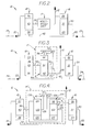
- Figure 1 is a diagrammatic, partial cross-section . of one example connected to a directional transmission unit;
- Figure 2 is a schematic diagram of the planetary differential shown in Figure 1;
- Figure 3 is a more detailed schematic diagram of the planetary differential illustrated in Figure 1 including, in phantom lines, an optional rotating clutch assembly;
- Figure 4 is a schematic diagram of a second example of a differential which provides four speeds;
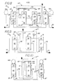
- Figure 5 is a schematic diagram of a third example;
- Figure 6 is a more detailed schematic diagram of the planetary differential illustrated in Figure 5;
- Figure 7 is a schematic diagram of a fourth example;
- Figure 8 is a schematic diagram of a fifth example;
- Figure 9 is a schematic diagram of a sixth example; and,
- Figure 10 is a schematic diagram of a seventh example.
- Referring initially to the diagrammatic drawing of Figure 2, a multi-speed
planetary differential 10 is shown in simplified form which has a driven rotary input member orgear 12, amulti-speed unit 14, first and secondplanetary sets second output members cross drive axis 24 disposed normal to the usual forward and reverse direction of vehicle travel. - The first
planetary set 16 includes ring, sun andcarrier elements similar planet elements 32 are rotatably mounted on the carrier element and are in intermeshing engagement with the ring and sun elements. In the instant example thecarrier element 30 is connected to the first orright output member 20. The secondplanetary set 18 also includes ring, sun andcarrier elements planet elements 40 rotatably mounted in equally spaced peripheral relationship on the carrier element. As is illustrated, thering element 34 is connected to the second orleft output member 22. Advantageously, theinput member 12 is connected to thering element 26 as well as to themulti-speed unit 14 to provide a common rotary drive. The output of the multi-speed unit is. connected to thecarrier element 38 of the second planetary set- 18, and thesun elements cross shaft 42 to complete the power flow path within thedifferential 10. Thus, in the broadest aspects of the construction illustrated in Fig. 2 themulti-speed unit 14 can provide two, three, four or even more speed steps and optional reversing capability to the first andsecond output members - More specifically, and with reference now to Figs. I and 3, one
multi-speed unit 14 can be noted to include a thirdplanetary set 44 having ring,sun'and carrier elements planet elements 52 rotatably mounted on the carrier element and in meshing engagement with the ring and sun elements. As can be noted from the instant example, thecarrier element 50 and thecarrier element 38 of the third and second planetary sets are integral with one another. The multi-speed unit further includes first and second brake assemblies generally designated by thereference numbers ring elements cross drive housing 58. These brake assemblies can be of conventional construction, and are illustrated as having a plurality of interleaved discs andplates annular piston 64 associated with each of the brake assemblies is nested in the housing so as to be moved to the left when viewing Fig. 1 by hydraulic fluid appropriately directed thereto for engaging the respective brake assembly. The pistons of the brake assemblies are urged back to the right toward their disengaged positions by coiled compression springs or the like, not shown. In the instant example the engagement of thefirst brake assembly 54 provides a low speed drive and the engagement of thesecond brake assembly 56 provides an intermediate speed drive. - A
hollow input shaft 66 is rotatably supported within thehousing 58 on a pair of opposedtapered bearing assemblies 68 in concentric relationship to thecross shaft 42 and thecross drive axis 24. Theinput gear 12 and thering element 26 of the firstplanetary set 16 are connected to thehollow input shaft 66 at the right end thereof, and thesun element 48 of the thirdplanetary set 44 is connected to the hollow input shaft at the left or opposite end thereof. - Preferably, a forward and reverse
directional transmission unit 70 is connected to theinput gear 12. This directional unit is adapted to longitudinally receive driving power from a prime mover or engine, not shown, via aninput pinion gear 72. The input pinion gear is in intermeshing engagement with left and rightannular bevel gears fixed housing 78 along a secondtransverse axis 80. Advantageously, left and right rotatingclutch assemblies output gear 86 connected thereto. Although these clutch assemblies are only diagrammatically illustrated it is to be understood that they can be of conventional construction also, such as by including a plurality of interleaved plates and discs of the general type described earlier with respect tobrake assemblies clutch assembly 84 is engaged, theright bevel gear 76 is directly connected to theoutput gear 86. On the other hand, when the reverse rotatingclutch assembly 82 is engaged theleft bevel gear 74 is connected to acentral cross shaft 88 which extends freely within the bevel gears. This cross shaft is rotatably supported by thehousing 78 viabearings 90 and is connected to theoutput gear 86 through an interconnecting member 92: - Turning now to the output sides of the multi- speed
planetary differential 10, it may be noted that on the left side when viewing Fig. 1 theoutput ring element 34 is rotatably supported within thehousing 58 by abearing assembly 94. The ring element is splined as at 96 to drivingly receive theleft output member 22. On the right side theoutput carrier element 30 is rotatably supported within the housing by anotherbearing assembly 98. The carrier element is likewise splined as at 100 to drivingly receive theright output member 20. What is of special note is that all rotating elements of theplanetary differential 10 are supported concentrically on theaxis 24 by means of only four bearing assemblies, namely,bearing assemblies - As shown in phantom lines centrally of Fig. 3, the multi-speed
planetary differential 10 can optionally include a direct drive in themulti-speed unit 14 by the addition of a rotatingclutch assembly 102. In effect, when actuated, the rotatingclutch assembly 102 connects thesun element 48 or thehollow input shaft 66 to thecarrier element 50 for joint rotation so that the third planetary set rotates as a unit to provide a relatively high speed output drive to theopposite output members - A multi-speed unit 14' is illustrated diagrammatically in Fig. 4, which is a variation of the multi-
speed unit 14 shown in Figs. 1-3. Those elements common to Figs. 1-3 are identified by similar reference numbers. Multi-speed unit 14' differs by having third and fourthplanetary sets 104 and 106, first andsecond brake assemblies 108 and 110, and first and second rotatingclutch assemblies planetary set 104 includes ring, sun andcarrier elements planet gears 122 intermeshingly connected to the ring and sun elements, and the fourth planetary set 106 includes ring, sun andcarrier.elements 124, 126.and 128.and a plurality ofplanet elements 130. The sun elements 118,126 of the third and fourth planetary sets are connected together for joint rotation, and thecarrier element 120 of the third planetary set is connected to thering element 124 of the fourth planetary set and also to thecarrier element 38 of the second planetary set for joint rotation. - In Fig. 5, another basic embodiment of the multi-speed planetary differential 10 is illustrated wherein the input member 12' has a different relationship to the first and second planetary sets 16' and 18'-when compared with Fig. 2. Elements similar to Figs. 1-4 are identified with the same reference character with one or two prime indicators thereon. In this example the input member 12' is connected to the carrier element 30' of the first planetary set 16' and to the multi-
speed unit 14". The output of the multi-speed unit is connected to the ring element 34' of the second planetary set 18'. This provides a reduction somewhat less than that of Fig. 2. - A specific example of the generalized Fig. 5 construction is illustrated in Fig. 6. Here the multi-
speed unit 14" includes a third planetary set 44' having-ring, sun andcarrier elements 461, 48' and 50' and plurality of planet elements 52'. Input is by way of the jointly connected carrier elements 30' and 50'. The sun element 48' is connected to the ring element 34' of the second planetary set, and abrake assembly 140 is associated therewith to provide a low speed. A rotatingclutch assembly 142 is provided to connect the carrier element 50' and the sun element 48' together for joint rotation to effect an intermediate speed mode of operation. Lastly, abrake assembly 144 is provided to hold the ring element 46' stationary to effect an overdrive or a high speed mode of operation. - An increased differential reduction is achieved in the example illustrated in Fig. 7, and while the planetary differential 10 bears a close resemblance to the construction of Fig. 3 it differs by utilizing a compound first planetary set 16" having ring, sun and
carrier elements 26", 28" and 30" and first and second pluralities of intermeshingplanet elements opposite ring elements 26", 34 and theoutput members - We also contemplate that the
multi-speed unit 14 can be modified to provide a reverse mode of operation of the planetary differential. Fig. 8 shows a three speed forward planetary differential with an added reverse speed. Themulti-speed unit 14"' thereof advantageously includes a compound fourthplanetary set 150 having ring, sun and carrier elements 152,154 and 156 and first and second pluralities of intermeshingplanet elements carrier elements sun elements brake assemblies clutch assembly 102 provides high speed. In this instance reverse is achieved by the engagement of anotherbrake assembly 164 that can selectively connect thering element 152 to thecross drive housing 58. - Another feature of the Fig. 8 construction is that the second planetary set 18" is also a compound set having first and second pluralities of intermeshing
planet elements ring element 34" thereof is connected for joint rotation with thecommon carrier elements brake assembly 54 is actuated. Advantageously, thecarrier element 38"of the second planetary set rotates with theoutput member 22 in a manner symmetrical withthe.carrier element 30 of the first planetary set 16 which rotates with theoutput member 20. The vehicle wheels 166,168 can be compactly connected to therespective carrier element - We further contemplate a forward and reverse
planetary differential 10 of the type illustrated in Fig. 9. While such construction does not have a plurality of speeds in a single direction, it does have two separate modes of operation. It can be appreciated from this illustration that the phrase "providing multi-speed capability" as defined herein can include a differential capable of driving theopposite output members sun elements ring elements planetary sets carrier elements second brake assemblies first brake assembly 162 stops rotation of thering elements second brake assembly 164 stops rotation of. thecarrier elements - Fig. 10 illustrates a variation of the Fig. 9 construction that offers compactness in a wheel tyred vehicle. The second and third
planetary sets carrier element 30" of the first planet set is connected to thering element 46 for joint rotation, and stopping of thering element 46 by actuation of thefirst brake assembly 162 provides forward rotation of the opposite wheels ortyres opposite ring elements 26" and 34 respectively. Stopping of thecarrier element 50 andcarrier element 38 as a unit by actuation of thesecond brake assembly 164 provides reverse drive. In this example each of the tyres 166,168 circumscribes or closely encircles one of thering elements 26",34 to provide a particularly compact and substantially direct and transversely centered interconnection. - The multi-speed planetary differential 10 is expected to find its greatest utility in a fork lift truck, automobile, or the like, wherein the
single input member 12 is powered by an engine and, if needed, via an intermediate transmission. Advantageously, substantially equal torque is delivered at all times to the opposite drive wheels of the vehicle by virtue of a preselected relationship between the first and second planetary sets 16,18. Such equal torque division provides directional stability when driving, and yet the differential function permits the wheels 166,168 to be operated at different rotational speeds in the same direction for vehicle turning or for wheel slippage under adverse traction conditions. - True differential action is obtained in the multi-speed planetary differential 10 by establishing the number of teeth in the rotating elements of the first and second planetary sets 16, 18 at preselected values. More specifically,, this is accomplished for simple planetary systems wherein the stated planetary sets have only a single plurality of planetary gears by selecting the ratio of the number of teeth of the ring element divided by the number of teeth of the sun element, hereinafter called the e value, such that the e value for the first planetary set 16 is equal to the e value for the second planetary set 18 minus one. For example, in the construction of Figs. 1 and 3, the number of teeth in the first planetary set ring and sun
elements elements carrier element 38 of the second planetary set of Fig. 3 is held stationary and that thering element 26 of the first planetary set is driven at a preselected speed. Then, under these conditions, thecarrier element 30 of the first planetary set and thering element 34 of the second planetary set will rotate at one-third of that preselected speed and in the same rotational direction as the input when viewing along theaxis 24. - Thus, it can be appreciated that in operation of the Figs. 1 and 3 embodiment, the actuation or engagement of the
first brake assembly 54 will stop rotation ofcarrier element 50 and integrally associatedcarrier element 38 to achieve a gear.reduction level of 3. That is, theoutput members input member 12 and in the same rotational direction, and the torque level at each of the output members'will be 1 1/2 times the input torque level. - The engagement of the
second brake assembly 56 will stop rotation of thering element 46 to give a preselected reduction level. In the instant example, the number of teeth of the ring and sunelements output members - Lastly, the engagement of rotating
clutch assembly 102 in Fig. 3 will couple the carrier andsun elements input member 12 is rotated at a preselected speed, then theoutput members - Turning next to the embodiment illustrated in Fig. 4, low or first speed is obtained by simultaneous engagement of
brake assemblies 108 and 110. This can give a reduction level of 3.' Second speed is obtained by simultaneous engagement ofbrake assembly 110 and rotatingclutch assembly 112. This can give a reduction level of 1.667. Third speed is obtained by simultaneous engagement of brake assembly 108 and rotatingclutch assembly 112 to give a reduction level of 1.286. And, with simultaneous engagement of rotatingclutch assemblies - In Fig. 6, the
multi-speed unit 14" provides low, intermediate and high speeds by the individual engagement ofbrake assembly 140, rotatingclutch assembly 142 andbrake assembly 144 respectively. In such example, the respective reductions are 1.5, 1.0 and 0.6. Thus, the high speed mode of operation is not a true reduction, but an overdrive. - In Fig. 7 the operation is like the Fig. 3 embodiment, with the engagement of
brake assembly 54 providing first speed and a reduction of 3.6. The actuation ofbrake assembly 56 gives a reduction of 1.93 for second speed. And the engagement of rotatingclutch assembly 102 provides a speed reduction level of one or unity for third gear. The first planetary set 16" in this instance has what we define as a negative e value because of the dualplanetary elements - Fig. 8 can provide first, second and third speeds by the individual engagement of
brake assembly 54, which stops rotation ofring element 34" andcarrier element 50,brake assembly 56 which stops rotation ofring element 46, and rotatingclutch assembly 102 which links the sun and carrier elements 154,156 together for joint rotation. Reverse is obtained by the actuation of the brake assembly.164 to stop the rotation of thering element 152 of theplanetary set 150 which has dual planetary elements 158,160. Reduction levels of 3.0, 1.8 and 1.0 can be obtained in the three forward speeds, and a reduction level of 3.0 can be obtained in reverse. In this example the respective e values for the various planetary sets are -4, +2, -2 and +2 reading from left to right when viewing Fig. 8. - In Fig. 9, if the e values of the first, second and third
planetary sets brake assembly 162, one unit of torque delivered to theinput member 12 can provide about 2.1 units of torque in the same rotational direction as the input member to each of theoutput members input member 12 can result in a speed reduction at theoutput members brake assembly 164, the torque level at theoutput members input member 12, and the speed reduction can be about 0.185. - In operation, the Fig. 10 differential can be constructed to be like that of Fig. 9 insofar as the speed reduction levels and torque multiplication factors are concerned. For example, e values of -3.0, 3.0 and 1.8 for the
planetary sets 16", 18 and 44 respectively can provide the same torque magnification values of 2.1 and 2.7 in forward and reverse respectively. - Thus, it may be appreciated that the multi- speed
planetary differential 10 of the present invention is compact and economical in construction, and the alignment of the principle elements thereof along a single transverse axis contributes to a relatively .simple housing and rotary bearing system to support the elements. A true differential action is always available while propelling the vehicle in a plurality of speeds, and this is particularly advantageous in the cross drive of a vehicle having separate steering wheels. For example, the multi-speed planetary differential 10 is extremely useful for the rear driving portion of a lift truck, automobile or the like having steerable wheels on the front portion thereof.
Claims (29)
Applications Claiming Priority (2)
| Application Number | Priority Date | Filing Date | Title |
|---|---|---|---|
| WOPCT/US80/00347 | 1980-03-31 | ||
| PCT/US1980/000347 WO1981002921A1 (en) | 1980-03-31 | 1980-03-31 | Multi-speed planetary differential |
Publications (3)
| Publication Number | Publication Date |
|---|---|
| EP0037183A2 true EP0037183A2 (en) | 1981-10-07 |
| EP0037183A3 EP0037183A3 (en) | 1982-06-23 |
| EP0037183B1 EP0037183B1 (en) | 1984-04-11 |
Family
ID=22154263
Family Applications (1)
| Application Number | Title | Priority Date | Filing Date |
|---|---|---|---|
| EP81300940A Expired EP0037183B1 (en) | 1980-03-31 | 1981-03-06 | Planetary differential |
Country Status (5)
| Country | Link |
|---|---|
| EP (1) | EP0037183B1 (en) |
| JP (1) | JPS57500346A (en) |
| CA (1) | CA1133282A (en) |
| ES (1) | ES8205047A1 (en) |
| WO (1) | WO1981002921A1 (en) |
Cited By (2)
| Publication number | Priority date | Publication date | Assignee | Title |
|---|---|---|---|---|
| WO1985001026A1 (en) * | 1983-08-25 | 1985-03-14 | Leyland Vehicles Limited | Drive line for a track-laying vehicle |
| EP2101085A1 (en) * | 2008-03-05 | 2009-09-16 | OMCI S.p.A. Officine Metalmeccaniche Costruzioni Industriali | A mechanical differential |
Families Citing this family (2)
| Publication number | Priority date | Publication date | Assignee | Title |
|---|---|---|---|---|
| JPH04101049U (en) * | 1991-02-01 | 1992-09-01 | 東洋運搬機株式会社 | drive unit |
| DE102017220166B3 (en) * | 2017-11-13 | 2019-03-14 | Audi Ag | Drive device for a vehicle axle of a two-lane vehicle |
Citations (7)
| Publication number | Priority date | Publication date | Assignee | Title |
|---|---|---|---|---|
| US2648236A (en) * | 1949-01-31 | 1953-08-11 | Kirkstall Forge Engineering Lt | Driving gear for the driven axles of vehicles |
| DE1103152B (en) * | 1958-04-09 | 1961-03-23 | Batignolles Chatillon | Gear shift and steering gear for caterpillar vehicles or the like. |
| US3144107A (en) * | 1955-07-25 | 1964-08-11 | Jered Ind Inc | Multiple speed transmission |
| US3377885A (en) * | 1965-06-28 | 1968-04-16 | Gen Motors Corp | Transmission |
| US3383953A (en) * | 1965-09-29 | 1968-05-21 | Gen Motors Corp | Power train |
| US4117744A (en) * | 1976-01-14 | 1978-10-03 | Deere & Company | Transmission for crawler tractors |
| US4184387A (en) * | 1976-07-21 | 1980-01-22 | Kubota, Ltd. | Vehicle for civil engineering work |
Family Cites Families (15)
| Publication number | Priority date | Publication date | Assignee | Title |
|---|---|---|---|---|
| US2164729A (en) * | 1937-03-05 | 1939-07-04 | Wilson Walter Gordon | Epicyclic power transmission mechanism |
| GB500054A (en) * | 1937-08-09 | 1939-02-02 | Andrew Gordon Wilson | Improvements in and relating to epicyclic reversing-gear |
| GB567635A (en) * | 1939-12-20 | 1945-02-26 | Henry Edward Merritt | Improvements in steering mechanisms for track-laying vehicles |
| US2689488A (en) * | 1950-08-11 | 1954-09-21 | Gen Motors Corp | Steering drive for vehicle transmissions |
| US2950634A (en) * | 1956-01-24 | 1960-08-30 | Letourneau Westinghouse Compan | Power train |
| US3039327A (en) * | 1956-12-28 | 1962-06-19 | Gen Motors Corp | Transmission |
| US2969695A (en) * | 1958-07-01 | 1961-01-31 | Gen Motors Corp | Transmission |
| US3107554A (en) * | 1961-02-24 | 1963-10-22 | Gen Motors Corp | Transmission |
| US3253688A (en) * | 1962-11-28 | 1966-05-31 | Gen Motors Corp | Transmission |
| US3405574A (en) * | 1966-07-18 | 1968-10-15 | Gen Motors Corp | Power train |
| US3820418A (en) * | 1972-08-21 | 1974-06-28 | Zahnradfabrik Friedrichshafen | Planetary gear transmission for automotive vehicles |
| JPS562223B2 (en) * | 1973-08-29 | 1981-01-19 | ||
| US4004473A (en) * | 1973-11-29 | 1977-01-25 | Caterpillar Tractor Co. | Broad range fluid and mechanical power transmission for vehicles or the like |
| US3996817A (en) * | 1974-08-27 | 1976-12-14 | Caterpillar Tractor Co. | Transmission including dual input clutch assembly |
| US4007648A (en) * | 1975-04-24 | 1977-02-15 | Ford Motor Company | Five-speed automatic transmission |
-
1980
- 1980-03-31 WO PCT/US1980/000347 patent/WO1981002921A1/en unknown
- 1980-03-31 JP JP55502330A patent/JPS57500346A/ja active Pending
- 1980-10-30 CA CA363,570A patent/CA1133282A/en not_active Expired
-
1981
- 1981-03-06 EP EP81300940A patent/EP0037183B1/en not_active Expired
- 1981-03-31 ES ES500889A patent/ES8205047A1/en not_active Expired
Patent Citations (7)
| Publication number | Priority date | Publication date | Assignee | Title |
|---|---|---|---|---|
| US2648236A (en) * | 1949-01-31 | 1953-08-11 | Kirkstall Forge Engineering Lt | Driving gear for the driven axles of vehicles |
| US3144107A (en) * | 1955-07-25 | 1964-08-11 | Jered Ind Inc | Multiple speed transmission |
| DE1103152B (en) * | 1958-04-09 | 1961-03-23 | Batignolles Chatillon | Gear shift and steering gear for caterpillar vehicles or the like. |
| US3377885A (en) * | 1965-06-28 | 1968-04-16 | Gen Motors Corp | Transmission |
| US3383953A (en) * | 1965-09-29 | 1968-05-21 | Gen Motors Corp | Power train |
| US4117744A (en) * | 1976-01-14 | 1978-10-03 | Deere & Company | Transmission for crawler tractors |
| US4184387A (en) * | 1976-07-21 | 1980-01-22 | Kubota, Ltd. | Vehicle for civil engineering work |
Cited By (3)
| Publication number | Priority date | Publication date | Assignee | Title |
|---|---|---|---|---|
| WO1985001026A1 (en) * | 1983-08-25 | 1985-03-14 | Leyland Vehicles Limited | Drive line for a track-laying vehicle |
| EP0141118A1 (en) * | 1983-08-25 | 1985-05-15 | Torotrak (Development) Limited | Driveline for a track-laying vehicle |
| EP2101085A1 (en) * | 2008-03-05 | 2009-09-16 | OMCI S.p.A. Officine Metalmeccaniche Costruzioni Industriali | A mechanical differential |
Also Published As
| Publication number | Publication date |
|---|---|
| ES500889A0 (en) | 1982-05-16 |
| CA1133282A (en) | 1982-10-12 |
| EP0037183B1 (en) | 1984-04-11 |
| JPS57500346A (en) | 1982-02-25 |
| ES8205047A1 (en) | 1982-05-16 |
| EP0037183A3 (en) | 1982-06-23 |
| WO1981002921A1 (en) | 1981-10-15 |
Similar Documents
| Publication | Publication Date | Title |
|---|---|---|
| US4357840A (en) | Multi-speed planetary differential | |
| US4624154A (en) | Drive unit for motor vehicle | |
| US4693134A (en) | High-powered vehicle drive train | |
| US5520588A (en) | Power transmission | |
| US4434680A (en) | Planetary steering differential | |
| US4976670A (en) | Power transmission | |
| US5518463A (en) | Torque distributing mechanism for differential | |
| US5466197A (en) | Mechanical-hydraulic transmission | |
| EP0339049A4 (en) | Countershaft transmission. | |
| JP3431928B2 (en) | Power transmission device | |
| EP0003397B1 (en) | Coaxial multi-range gear train for transmissions | |
| EP0025499A2 (en) | Differential for multiplying torquing force and drive train | |
| US4682515A (en) | Gear train for four range hydromechanical steering transmission | |
| US4423644A (en) | Multi-speed planetary differential | |
| WO1988002452A1 (en) | Countershaft transmission | |
| US4215755A (en) | Power transmission mechanisms | |
| EP0037183B1 (en) | Planetary differential | |
| US6338689B1 (en) | Hydromechanical transmission | |
| EP0141118A1 (en) | Driveline for a track-laying vehicle | |
| CA1133281A (en) | Multi-speed planetary diffenential | |
| CN105927719A (en) | Multi-speed Tranmission | |
| US3968704A (en) | Power transfer mechanism | |
| US4706517A (en) | Automatic power transmission mechanism for a four wheel drive vehicle | |
| EP0058666B1 (en) | Planetary steering differential | |
| US4617836A (en) | Transmission systems for tracked vehicles |
Legal Events
| Date | Code | Title | Description |
|---|---|---|---|
| PUAI | Public reference made under article 153(3) epc to a published international application that has entered the european phase |
Free format text: ORIGINAL CODE: 0009012 |
|
| 17P | Request for examination filed |
Effective date: 19810313 |
|
| AK | Designated contracting states |
Designated state(s): FR GB IT |
|
| PUAL | Search report despatched |
Free format text: ORIGINAL CODE: 0009013 |
|
| AK | Designated contracting states |
Designated state(s): FR GB IT |
|
| ITF | It: translation for a ep patent filed |
Owner name: ING. ZINI MARANESI & C. S.R.L. |
|
| GRAA | (expected) grant |
Free format text: ORIGINAL CODE: 0009210 |
|
| AK | Designated contracting states |
Designated state(s): FR GB IT |
|
| ET | Fr: translation filed | ||
| PGFP | Annual fee paid to national office [announced via postgrant information from national office to epo] |
Ref country code: FR Payment date: 19841205 Year of fee payment: 5 |
|
| PLBE | No opposition filed within time limit |
Free format text: ORIGINAL CODE: 0009261 |
|
| STAA | Information on the status of an ep patent application or granted ep patent |
Free format text: STATUS: NO OPPOSITION FILED WITHIN TIME LIMIT |
|
| 26N | No opposition filed | ||
| REG | Reference to a national code |
Ref country code: GB Ref legal event code: 732 |
|
| ITPR | It: changes in ownership of a european patent |
Owner name: CESSIONE;CATERPILLAR INC. |
|
| REG | Reference to a national code |
Ref country code: FR Ref legal event code: TP |
|
| PG25 | Lapsed in a contracting state [announced via postgrant information from national office to epo] |
Ref country code: GB Free format text: LAPSE BECAUSE OF NON-PAYMENT OF DUE FEES Effective date: 19881118 |
|
| GBPC | Gb: european patent ceased through non-payment of renewal fee | ||
| PG25 | Lapsed in a contracting state [announced via postgrant information from national office to epo] |
Ref country code: FR Free format text: LAPSE BECAUSE OF NON-PAYMENT OF DUE FEES Effective date: 19881130 |
|
| REG | Reference to a national code |
Ref country code: FR Ref legal event code: ST |