EP4105407A1 - Insulated fibre reinforced wall panel - Google Patents
Insulated fibre reinforced wall panel Download PDFInfo
- Publication number
- EP4105407A1 EP4105407A1 EP22189052.8A EP22189052A EP4105407A1 EP 4105407 A1 EP4105407 A1 EP 4105407A1 EP 22189052 A EP22189052 A EP 22189052A EP 4105407 A1 EP4105407 A1 EP 4105407A1
- Authority
- EP
- European Patent Office
- Prior art keywords
- wall panel
- layer
- brick
- middle layer
- veneer
- Prior art date
- Legal status (The legal status is an assumption and is not a legal conclusion. Google has not performed a legal analysis and makes no representation as to the accuracy of the status listed.)
- Pending
Links
Images


Classifications
-
- E—FIXED CONSTRUCTIONS
- E04—BUILDING
- E04F—FINISHING WORK ON BUILDINGS, e.g. STAIRS, FLOORS
- E04F13/00—Coverings or linings, e.g. for walls or ceilings
- E04F13/07—Coverings or linings, e.g. for walls or ceilings composed of covering or lining elements; Sub-structures therefor; Fastening means therefor
- E04F13/08—Coverings or linings, e.g. for walls or ceilings composed of covering or lining elements; Sub-structures therefor; Fastening means therefor composed of a plurality of similar covering or lining elements
- E04F13/14—Coverings or linings, e.g. for walls or ceilings composed of covering or lining elements; Sub-structures therefor; Fastening means therefor composed of a plurality of similar covering or lining elements stone or stone-like materials, e.g. ceramics concrete; of glass or with an outer layer of stone or stone-like materials or glass
- E04F13/147—Coverings or linings, e.g. for walls or ceilings composed of covering or lining elements; Sub-structures therefor; Fastening means therefor composed of a plurality of similar covering or lining elements stone or stone-like materials, e.g. ceramics concrete; of glass or with an outer layer of stone or stone-like materials or glass with an outer layer imitating natural stone, brick work or the like
-
- E—FIXED CONSTRUCTIONS
- E04—BUILDING
- E04F—FINISHING WORK ON BUILDINGS, e.g. STAIRS, FLOORS
- E04F13/00—Coverings or linings, e.g. for walls or ceilings
- E04F13/07—Coverings or linings, e.g. for walls or ceilings composed of covering or lining elements; Sub-structures therefor; Fastening means therefor
- E04F13/08—Coverings or linings, e.g. for walls or ceilings composed of covering or lining elements; Sub-structures therefor; Fastening means therefor composed of a plurality of similar covering or lining elements
- E04F13/0862—Coverings or linings, e.g. for walls or ceilings composed of covering or lining elements; Sub-structures therefor; Fastening means therefor composed of a plurality of similar covering or lining elements composed of a number of elements which are identical or not, e.g. carried by a common web, support plate or grid
-
- E—FIXED CONSTRUCTIONS
- E04—BUILDING
- E04F—FINISHING WORK ON BUILDINGS, e.g. STAIRS, FLOORS
- E04F13/00—Coverings or linings, e.g. for walls or ceilings
- E04F13/07—Coverings or linings, e.g. for walls or ceilings composed of covering or lining elements; Sub-structures therefor; Fastening means therefor
- E04F13/08—Coverings or linings, e.g. for walls or ceilings composed of covering or lining elements; Sub-structures therefor; Fastening means therefor composed of a plurality of similar covering or lining elements
- E04F13/0866—Coverings or linings, e.g. for walls or ceilings composed of covering or lining elements; Sub-structures therefor; Fastening means therefor composed of a plurality of similar covering or lining elements composed of several layers, e.g. sandwich panels or layered panels
-
- E—FIXED CONSTRUCTIONS
- E04—BUILDING
- E04F—FINISHING WORK ON BUILDINGS, e.g. STAIRS, FLOORS
- E04F13/00—Coverings or linings, e.g. for walls or ceilings
- E04F13/07—Coverings or linings, e.g. for walls or ceilings composed of covering or lining elements; Sub-structures therefor; Fastening means therefor
- E04F13/08—Coverings or linings, e.g. for walls or ceilings composed of covering or lining elements; Sub-structures therefor; Fastening means therefor composed of a plurality of similar covering or lining elements
- E04F13/0875—Coverings or linings, e.g. for walls or ceilings composed of covering or lining elements; Sub-structures therefor; Fastening means therefor composed of a plurality of similar covering or lining elements having a basic insulating layer and at least one covering layer
Definitions
- the invention relates to the field of building construction materials. More particularly, the invention relates to the field of construction components used in the construction of walls, ceilings, and other planar, angled, and curved surfaces for buildings.
- bricks are capable of resisting high summer heat as well as cold winters and changes there between. In addition to such thermal properties, brick provides a strong outer shell to a building. Brick resists wind, rain, snow, dust and other detrimental environmental elements. Brick can be fire retardant surface for buildings. Bricks can be manufactured in a myriad of sizes, textures, and colors. Further, though it need not be painted, when brick is painted, the paint adheres well to the brick.
- brick has a few drawbacks, mostly related to installation. For instance, whereas other exterior surfaces may be relatively easily applied to an existing building structure, brick is much more difficult to install on an existing building as an alternate siding choice during a renovation. Further, the laying of brick during the construction of a building is a labor intensive operation. Each brick must be mortared and laid, one on another, brick by brick, by a skilled brick mason. As manual labor prices rise in a given market, so do the costs associated with using brick as a building material. It is also difficult or impossible to install brick during the winter because mortar does not cure well or at all in freezing temperatures.
- the present invention is thus a wall panel system that exhibits many of the same characteristics as traditional brick without the need for extensive labor costs associated with traditional brick masonry. Further, the invention is not limited to new construction applications but may be utilized in existing construction as a retrofit application.
- the invention has the same aesthetic appeal as traditional brick and has the same or better engineering benefits.
- the invention functions as a structural element of the building, a water-resistive barrier, a fire retardant layer, an insulating envelope, and an aesthetic finished exterior surface.
- the invention is lightweight and energy efficient.
- the invention may include an outer veneer layer, a middle cement layer, and an inner insulation layer.
- the outer veneer layer may be thin brick, stone, tile, or other such material (hereinafter referred to as "brick” unless otherwise specificed) as desired for both aesthetic and engineering appeal. These may be referred to as an architectural or aesthetic element.
- the outer veneer layer may be two parts comprising thin brick, stone, tile or other material which is embedded in a substrate. This substrate may be a polyurethane or other plastic.
- the brick is placed in a mold according to a desired pattern and the polyurethane, plastic, or other material is pour into the mold and bonds to the brick. A finished surface of the brick will extend above the level of the poured substrate once the substrate hardens.
- the substrate may have sand added so that a top surface of the substrate, visible between the brick, has the appearance mortar.
- additional mortar or mortar substitute such as a sanded glue
- the middle cement layer may be glass fiber reinforced concrete.
- the middle cement layer may be Magnesium Oxide.
- the middle cement layer may be poured and cured in place or it may be sourced as a pre-fabricated product, particularly with respect to the Magnesim Oxide material.
- the inner insulation layer may include a rigid pour foam which may be a two part rigid pour urethane foam.
- a wall panel may include a poured substrate selected from the group consisting of polyurethane and plastic.
- the wall panel may further include a plurality of aesthetic elements, embedded in and bonded to the poured substrate.
- the aesthetic elements may be selected from the group consisting of brick, ceramic tile, porcelain tile, natural stone, engineered stone, wood, ceramic, plastic, and vinyl.
- a finished surface of the aesthetic elements may extend above a top surface of the poured substrate.
- each one of the aesthetic elements may be arranged in spaced-apart relation to another one of the aesthetic elements.
- the wall panel may include a middle layer having a first side which is attached to a rear surface of the poured substrate.
- the wall panel may also include an insulation layer having a first side chemically bonded to a second side of the middle layer.
- the insulation layer may include a two part rigid urethane pour foam the insulation layer may be chemically bonded to the middle layer during a pour.
- the middle layer may be magnesium oxide.
- the middle layer may be fiber reinforced cement.
- the middle layer may be attached to the poured substrate using an attachment means such as screws, nails, bolts, welds, construction adhesive, rivets, and clasps.
- the wall panel may be attached to a building structure using an attachment means such as screws, nails, bolts, welds, construction adhesive, rivets, and clasps.
- the poured substrate may also include sand, causing the top surface of the poured substrate to have an appearance of mortar.
- the wall panel may further include sanded glue for covering imperfections in the top surface of the poured substrate and for causing the top surface of the poured substrate to have an appearance of mortar.
- a wall panel may include a middle layer made from magnesium oxide.
- the middle layer may have a first and a second side.
- a veneer layer may be attached to the first side of the middle layer.
- the veneer layer may include one or more of of brick, ceramic tile, porcelain tile, natural stone, engineered stone, wood, ceramic, plastic, vinyl, and paint.
- an insulation layer may have a first side chemically bonded to a second side of the middle layer.
- the insulation layer may include a two part rigid urethane pour foam and the insulation layer may be chemically bonded to the middle layer during a pour.
- a wall panel may include a middle layer made from a magnesium oxide.
- the middle layer may have a first and a second side.
- the wall panel may also include a veneer layer attached to the first side of the middle layer.
- the wall panel may also have an insulation layer.
- the insulation layer may have a first side chemically bonded to a second side of the middle layer.
- the insulation layer may be made from a two part rigid urethane pour foam may be chemically bonded to the middle layer during a pour.
- the inner insulation layer is poured onto and is fixedly attached to the middle cement layer.
- the outer veneer layer is attached to the middle cement layer with mortar or other cement product.
- the substrate of the veneer layer may be attached to the middle cement layer via attachment screws (or nails, wall ties, or other similar attachment means). Such attachment screws may be positioned between spacing in the brick and extend through the substrate of the veneer layer into the cement layer and even into the insulation layer. Preferably, the screws of the veneer do not extend beyond the insulation layer in exterior applications.
- the veneer layer may be attached to the middle layer with a chemical or other construction adhesive.
- the adhesive may be either one part design or of multi-part design.
- the veneer layer may be brick, tile, stone, engineered stone, or other such product as desired for aesthetic purposes.
- the mortar or other adhesive used to attach the veneer layer may also be used to grout lines between the bricks, stone, or tile of the veneer layer or another product may be applied as a grout.
- the veneer layer may include spaced apart latitudinal ridges on a rear surface of the veneer layer.
- Such latitudinal ridges may be narrower in width than the space between the ridges.
- the latitudinal ridges may create channels for moisture, gas, and other fluids which may accumulate between the veneer layer and the middle layer to escape.
- the middle cement layer may include relief lines or guide lines.
- the relief lines function to provide a guide when attaching the veneer layer to the cement layer.
- the relief lines will be in the shape of the rectangular brick and be just larger than the perimeter of the brick such that the brick fits snuggly inside the relief lines upon application.
- the relief lines will match and be just larger than the perimeter of the stone to be installed.
- the respective inner layer and middle cement layer are constructed into panels designed to be attached to a building frame.
- the panels may be attached directly to the studs of a building or they may be attached to some other structural component of the building.
- the panels are attached using screws such as structural insulated panel (SIP) screws.
- SIP screws attach to the building through holes in the panel.
- the holes may be countersunk so that the head of the screws is flush with the surface of the panel.
- attachment points, or other items such as a pvc inlay may be incorporated into middle cement layer.
- Such items will be of a material that does not negatively impact the performance or other property of the insulation or otherwise cause a conductive source of thermal wicking.
- the panels are attached using nails, construction adhesive, bolts, rivets, clasps, or other such attachment devices.
- the seams between the panels are sealed.
- the veneer layer is applied over the middle cement layer.
- screws may be used to attach the veneer layer to the middle cement layer as described above.
- mortar or other attachment material is applied over the panels and the brick or other material is fitted between the relief lines.
- the bricks cover the holes of the SIP screws and also, importantly, cover the seams of the panels. Thus, there are no exposed joints or other openings of the panels.
- trim pieces are applied around openings in the building envelope such as around windows and doors.
- These trim pieces may be in the form of headers and may include various shapes as desired for structural and aesthetic purposes.
- the trim pieces may be formed in the two part manner as described above with respect to the veneer layer. That is, the trim pieces may comprise brick embedded in a substrate.
- the brick may be arranged in a mold and may be coated with wax.
- the liquid substrate (such as polyurethane, plastic, cement, glue, or other material) may be poured into the mold around the brick. This substrate bonds to the brick.
- corner pieces are attached to the panel ends at corners of the building, or wherever corners may be required, and then brick or other material as desired is placed over the corner pieces just with the panels.
- the corner pieces may alternatively be formed using the two-part veneer system as described above with respect to the trim pieces and the outer veneer layer.
- the panels provide a continuous insulating envelope for the walls of a structure.
- the inner insulation layer may be one inch and may also be up to or greater than three inches thick.
- Such insulation may provide the panels with an insulation factor of R7 to R21 or greater depending on various factors of design.
- Such an insulation regime applied to outer walls of a structure may, depending on other building and environmental factors such as zoning, building codes, etc..., free up space within stud walls for other building elements such as wiring, plumbing etc... and may also reduce the size studs required for a particular building plan. For instance, whereas 2X6 or 2X8 studs may have been required to achieve a desired insulation factor, by utilizing the invention as an exterior envelope, 2X4 studs may suffice. Similarly, in a retrofit application, where an older building may have little or no insulation, significant insulation, in addition to aesthetic elements, can be gained by applying the invention to the pre-existing building.
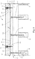
- the invention is an insulated wall panel 10 having three layers, 20, 30, and 40.
- the panel 10 provides a finished aesthetic surface to a building, a structural component to a building, and an insulation factor for a building.
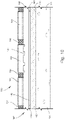
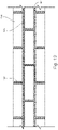
- the installed wall panel 10 includes an inner insulation layer 20, a middle cement layer 30, and an outer veneer layer 40.
- the panel 10 may be attached to a building wall 50.
- the outer veneer layer 40 may include brick (as shown in the drawings) but may also include stone, tile, engineered stone, and/or similar material depending on desired finish effect. Thus, the use of the term "brick” herein is synonymous and inclusive of other veneers thus listed.
- the veneer layer 40 is relatively thin and is attached to the middle cement layer 30 using mortar 44 or other appropriate material such as a chemical adhesive as best shown in Fig. 4 .
- Each brick (or other material as desired) of the veneer layer 40 is thin and is defined by a perimeter.
- the middle layer 30 provides a substrate to which the brick of the veneer 40 is applied upon installation on a building structure 50.
- the middle layer 30 has a plurality of sets of relief lines 32.
- Each set of relief lines 32 define a boundary that is just larger than the perimeter of a particular brick of the veneer layer 40 that is to be applied to the middle layer 30.
- the relief lines 32 may be formed to the thickness of the desired grout 42 spacing between the brick of the veneer layer 40.
- the middle layer 30 is made of a cementatious product with a glass fiber reinforcing material embedded therein.
- the glass fiber has a high strength and is the principal load-carrying member of the middle layer 30 while the cement forms a matrix that allows the fibers to retain their desired location and orientation.
- the resultant product is thin and strong.
- a mold is first constructed into which a slurry of uncured cementatious product of the middle layer 30 is poured.
- the mold will have the negatives of the relief lines 32 formed therein. These negatives will appear as small trenches within the mold such that when the cement cures and the middle layer 30 is removed from the mold, the relief lines 32 will protrude outward from the otherwise generally planar outer surface 34 of the middle layer.
- the inner surface 36 of the middle layer 30 will also be generally planar but will not have such relief lines 32.
- the middle layer 30 may remain in the mold while curing. Curing time is dependent upon the thickness, particulars of the mix design, and the environment in which the cement is being cured.
- the middle cement layer 30 is cured in a chamber.
- the inner insulation layer 20 is a rigid pour foam that is formed from a two part Class I rated urethane.
- the foam is non-CFC and non-HCFC.
- the foam is applied to the inner surface 36 of the middle layer 30 using a machine calibrated to deliver proper and consistent component mix.
- the finished urethane material 20 will have an in place density of approximately 2.2 pounds per cubic foot.
- the foam 20 adheres to the middle layer 30 such that the machine delivery and mixing of the components provides for a complete bond between the middle layer 30 and inner insulation layer 20. Thus, there are no adhesives or other chemical bonding required to achieve the strength of the final insulated panel 10.
- the inner insulation layer 20 may be one inch thick or up to three inches thick or greater depending on the level of insulation desired for a particular application.
- the middle layer 30 may be press-molded, extruded, vibration cast, sprayed, or slip formed. If, in alternate embodiments, attachment points or other items are incorporated into the structure they are placed in the mold prior to the injection of the urethane.
- the panel 10 is in condition for application to a building 50.
- the panels 10 are screwed with screws 52 to the wall 50 or other structural element of a building. End pieces, headers, and other trim pieces, having been similarly manufactured, are likewise attached to the building.
- the seams 22 between the respective panels and trim pieces are sealed with a sealing compound, such as Laticrete ® Air and Water Barrier.
- a sealing compound such as Laticrete ® Air and Water Barrier.
- an adhesive such as mortar 44 is applied to the outer surface of the middle layer 30.
- the brick of the veneer layer 40 are applied on top of the adhesive 44 and between the relief lines 32.
- the brick of the veneer 40 are applied to overlap 38 the seams 22 in the panels 10. This overlapping 38 of the seams is best shown in Figs. 4 and 5 .
- a grout 42 or other material is applied between the gaps in the brick of the veneer 40.
- the invention includes an embodiment 100 utilizing a two-part veneer layer 140.
- the top part of the veneer layer may brick 146 as shown.
- the invention contemplates that the concrete, tile, stone, wood, plastic, vinyl, and other materials may be utilized.
- the term "brick" will include all other such materials.
- the invention may utilize a middle layer 130.
- This middle layer 130 may be formed from cement or from Magnesium Oxide or from another composite material.
- an insulating layer 120 is adhered to the middle layer 120.
- the inner insulation layer 120 is preferably a rigid pour foam that is formed from a two part Class I rated urethane.
- the brick 146 is embedded in a substrate 144.
- This substrate 144 may be a polyurethane or other plastic, cement, glass fiber reinforced concrete (GFRC), ceramic, or other composite liquid product.
- the two part layer is formed by having the brick 146 positioned in a mold according to desired pattern.
- the brick 146 may be coated with wax or other protective coating. Sand may be utilized as a release agent.
- the substrate 144 is then poured into the mold and surrounds a lower portion of the brick 146, thereby embedding the brick 146 in the substrate 144 as the substrate hardens.
- the brick 146 may have a smooth lower surface or may have notches which may be dovetail notches 145 as shown in Fig. 10 .
- the mold (not shown) includes a plurality of parallel grooves which, when filled with the substrate 144 form ridges 148 in the substrate 144. These ridges 148 may be seen in the assembled sectional views of Figs. 8 , 9 , and 10 . Between each ridge is a void 149 which forms a channel through which moisture, water, and other fluids may pass between the substrate 144 and the middle cement layer 130. Such fluid may exit through weep holes (not shown). For interior application, no such void 149 may be necessary and the substrate layer 144 may not have the ridges and may be directly attached to the middle layer 130. Likewise, for interior application, the middle layer 130 and the insulation layer 120 may not be used and the substrate may be adhered directly to an underlying construction element such as stud walls.
- the two-part veneer layer 140 may be supplied to building contractors as one element and the combination of the middle layer 130 and insulation layer 120 may be supplied to building contractors as a second element.
- the second element 120, 130 may be attached via attachment means such as screws 152 to a block wall 150 as shown in Fig. 6 or studs 151 as shown in Fig. 9 .
- the first element 140 may be attached to the first element 120, 130 via attachment means such as screws 154.
- screws 154 do not extend all the way through the second element 120, 130 so that the thermal barrier is not breached.
- This grout/mortar 142 may conceal screw heads/holes as shown in Fig. 9 .
- Different grout/mortar joints are possible including raked, grapevine, extruded, concave, V, struck, flush, weathered, struck, and convex.
- the substrate 144 may additionally comprise a sand additive which mimics the appearance of grout.
- no additional grout/mortar needs to be added following installation of the top veneer layer except that a small amount of grout/mortar or an equivalent matching concealer such as caulk may be added to conceal screw/attachment heads and/or joints between panels.
- the above description has contemplated use in a wall system for either exterior or interior use.
- the invention 100 contemplates use both in ceiling applications (not shown) and in paving and flooring applications (not shown).
- the joints between panels of the top two-part veneer layer 140 may be staggered to form an interlocking pattern. It is contemplated that panels of the invention 100 may be cut as needed in a particular application. Corners, reliefs, window edging, keystones, and starter courses are also contemplated under the same methods as discussed above.
- a wall panel system 10, 100 according to the invention has been described with reference to specific embodiments and examples. Various details of the invention may be changed without departing from the scope of the invention. Furthermore, the foregoing description of the preferred embodiments of the invention and best mode for practicing the invention are provided for the purpose of illustration only and not for the purpose of limitation, the invention being defined by the claims. It is envisioned that other embodiments may perform similar functions and/or achieve similar results. Any and all such equivalent embodiments and examples are within the scope of the present invention and are intended to be covered by the appended claims.
Abstract
Description
- The invention relates to the field of building construction materials. More particularly, the invention relates to the field of construction components used in the construction of walls, ceilings, and other planar, angled, and curved surfaces for buildings.
- Humans have utilized bricks and other hard surfaces as construction components for buildings for thousands of years. The earliest sun dried bricks were made in Ancient Egypt. Later, bricks were dried using a fuel source. The Book of Genesis records that burnt brick was used in the construction of the Tower of Babel. Thus, from ancient times to the present, brick has remained a popular building material.
- The enduring presence of brick is due in no small part to its stellar properties as an exterior surface. Bricks are capable of resisting high summer heat as well as cold winters and changes there between. In addition to such thermal properties, brick provides a strong outer shell to a building. Brick resists wind, rain, snow, dust and other detrimental environmental elements. Brick can be fire retardant surface for buildings. Bricks can be manufactured in a myriad of sizes, textures, and colors. Further, though it need not be painted, when brick is painted, the paint adheres well to the brick.
- However, despite such positive characteristics, brick has a few drawbacks, mostly related to installation. For instance, whereas other exterior surfaces may be relatively easily applied to an existing building structure, brick is much more difficult to install on an existing building as an alternate siding choice during a renovation. Further, the laying of brick during the construction of a building is a labor intensive operation. Each brick must be mortared and laid, one on another, brick by brick, by a skilled brick mason. As manual labor prices rise in a given market, so do the costs associated with using brick as a building material. It is also difficult or impossible to install brick during the winter because mortar does not cure well or at all in freezing temperatures.
- Thus, there exists a need for a building product that has the same or better building characteristics and aesthetic appeal as traditional brick but also can be applied without the need for an extensive skilled labor team of brick masons. Further, there exists a need for a building product that has the same or better building characteristics and aesthetic appeal as traditional brick that may be used as a retro-fit product for providing a siding to an existing building structure. Further, as energy costs and environmental consciousness increase, so to does the demand for better insulation. Thus, there is also a need for building materials offering improved insulation of a building's envelope.
- The present invention is thus a wall panel system that exhibits many of the same characteristics as traditional brick without the need for extensive labor costs associated with traditional brick masonry. Further, the invention is not limited to new construction applications but may be utilized in existing construction as a retrofit application.
- The invention has the same aesthetic appeal as traditional brick and has the same or better engineering benefits. The invention functions as a structural element of the building, a water-resistive barrier, a fire retardant layer, an insulating envelope, and an aesthetic finished exterior surface. The invention is lightweight and energy efficient.
- The invention may include an outer veneer layer, a middle cement layer, and an inner insulation layer.
- The outer veneer layer may be thin brick, stone, tile, or other such material (hereinafter referred to as "brick" unless otherwise specificed) as desired for both aesthetic and engineering appeal. These may be referred to as an architectural or aesthetic element. Alternatively, the outer veneer layer may be two parts comprising thin brick, stone, tile or other material which is embedded in a substrate. This substrate may be a polyurethane or other plastic. According to this two part veneer layer embodiment of the invention, the brick is placed in a mold according to a desired pattern and the polyurethane, plastic, or other material is pour into the mold and bonds to the brick. A finished surface of the brick will extend above the level of the poured substrate once the substrate hardens. According to another embodiment of the invention, the substrate may have sand added so that a top surface of the substrate, visible between the brick, has the appearance mortar. In the above example, additional mortar or mortar substitute (such as a sanded glue) may be used to cover any screw holes or gaps between sections.
- The middle cement layer may be glass fiber reinforced concrete. Alternatively, the middle cement layer may be Magnesium Oxide. The middle cement layer may be poured and cured in place or it may be sourced as a pre-fabricated product, particularly with respect to the Magnesim Oxide material.
- The inner insulation layer may include a rigid pour foam which may be a two part rigid pour urethane foam.
- According to one embodiment of the invention, a wall panel may include a poured substrate selected from the group consisting of polyurethane and plastic. The wall panel may further include a plurality of aesthetic elements, embedded in and bonded to the poured substrate. According to such an embodiment, the aesthetic elements may be selected from the group consisting of brick, ceramic tile, porcelain tile, natural stone, engineered stone, wood, ceramic, plastic, and vinyl. According to such an embodiment, a finished surface of the aesthetic elements may extend above a top surface of the poured substrate. According to such an embodiment, each one of the aesthetic elements may be arranged in spaced-apart relation to another one of the aesthetic elements.
- According to another embodiment of the invention, the wall panel may include a middle layer having a first side which is attached to a rear surface of the poured substrate. The wall panel may also include an insulation layer having a first side chemically bonded to a second side of the middle layer. According to such an embodiment, the insulation layer may include a two part rigid urethane pour foam the insulation layer may be chemically bonded to the middle layer during a pour.
- According to another embodiment of the invention the middle layer may be magnesium oxide.
- According to another embodiment of the invention, the middle layer may be fiber reinforced cement.
- According to another embodiment of the invention, the middle layer may be attached to the poured substrate using an attachment means such as screws, nails, bolts, welds, construction adhesive, rivets, and clasps.
- According to another embodiment of the invention, the wall panel may be attached to a building structure using an attachment means such as screws, nails, bolts, welds, construction adhesive, rivets, and clasps.
- According to another embodiment of the invention, the poured substrate may also include sand, causing the top surface of the poured substrate to have an appearance of mortar.
- According to another embodiment of the invention, the wall panel may further include sanded glue for covering imperfections in the top surface of the poured substrate and for causing the top surface of the poured substrate to have an appearance of mortar.
- According to one embodiment of the invention, a wall panel may include a middle layer made from magnesium oxide. The middle layer may have a first and a second side. A veneer layer may be attached to the first side of the middle layer. According to such an embodiment, the veneer layer may include one or more of of brick, ceramic tile, porcelain tile, natural stone, engineered stone, wood, ceramic, plastic, vinyl, and paint.
- According to another embodiment of the invention, an insulation layer may have a first side chemically bonded to a second side of the middle layer. The insulation layer may include a two part rigid urethane pour foam and the insulation layer may be chemically bonded to the middle layer during a pour.
- According to one embodiment of the invention, a wall panel may include a middle layer made from a magnesium oxide. The middle layer may have a first and a second side. The wall panel may also include a veneer layer attached to the first side of the middle layer. The wall panel may also have an insulation layer. The insulation layer may have a first side chemically bonded to a second side of the middle layer. The insulation layer may be made from a two part rigid urethane pour foam may be chemically bonded to the middle layer during a pour.
- In one embodiment, the inner insulation layer is poured onto and is fixedly attached to the middle cement layer. The outer veneer layer is attached to the middle cement layer with mortar or other cement product. Alternatively, in the embodiment that utilizes the two-part veneer layer, the substrate of the veneer layer may be attached to the middle cement layer via attachment screws (or nails, wall ties, or other similar attachment means). Such attachment screws may be positioned between spacing in the brick and extend through the substrate of the veneer layer into the cement layer and even into the insulation layer. Preferably, the screws of the veneer do not extend beyond the insulation layer in exterior applications.
- According to another embodiment, the veneer layer may be attached to the middle layer with a chemical or other construction adhesive. The adhesive may be either one part design or of multi-part design.
- According to another embodiment of the invention, the veneer layer may be brick, tile, stone, engineered stone, or other such product as desired for aesthetic purposes. The mortar or other adhesive used to attach the veneer layer may also be used to grout lines between the bricks, stone, or tile of the veneer layer or another product may be applied as a grout.
- According to another embodiment of the invention, the veneer layer may include spaced apart latitudinal ridges on a rear surface of the veneer layer. Such latitudinal ridges may be narrower in width than the space between the ridges. The latitudinal ridges may create channels for moisture, gas, and other fluids which may accumulate between the veneer layer and the middle layer to escape.
- According to one embodiment of the invention, in embodiments where a two part veneer layer is not used and the brick are adhered directly to the cement layer, the middle cement layer may include relief lines or guide lines. The relief lines function to provide a guide when attaching the veneer layer to the cement layer. For example, when the veneer layer uses rectangular brick, the relief lines will be in the shape of the rectangular brick and be just larger than the perimeter of the brick such that the brick fits snuggly inside the relief lines upon application. Similarly, if stone is the veneer layer, the relief lines will match and be just larger than the perimeter of the stone to be installed.
- According to another embodiment of the invention, the respective inner layer and middle cement layer are constructed into panels designed to be attached to a building frame. The panels may be attached directly to the studs of a building or they may be attached to some other structural component of the building.
- According to another embodiment of the invention, the panels are attached using screws such as structural insulated panel (SIP) screws. The SIP screws attach to the building through holes in the panel. The holes may be countersunk so that the head of the screws is flush with the surface of the panel.
- According to another embodiment, attachment points, or other items such as a pvc inlay may be incorporated into middle cement layer. Such items will be of a material that does not negatively impact the performance or other property of the insulation or otherwise cause a conductive source of thermal wicking.
- According to another embodiment of the invention, the panels are attached using nails, construction adhesive, bolts, rivets, clasps, or other such attachment devices.
- According to another embodiment of the invention, once the panels are attached to the building, the seams between the panels are sealed.
- According to another embodiment of the invention, once sealed, the veneer layer is applied over the middle cement layer. In embodiments utilizing the two-part veneer layer, screws may be used to attach the veneer layer to the middle cement layer as described above. However, in the embodiments where the brick is attached directly to the cement layer (the embodiment without the substrate in the veneer layer), during application, mortar or other attachment material is applied over the panels and the brick or other material is fitted between the relief lines. The bricks cover the holes of the SIP screws and also, importantly, cover the seams of the panels. Thus, there are no exposed joints or other openings of the panels.
- According to another embodiment of the invention, trim pieces are applied around openings in the building envelope such as around windows and doors. These trim pieces may be in the form of headers and may include various shapes as desired for structural and aesthetic purposes. The trim pieces may be formed in the two part manner as described above with respect to the veneer layer. That is, the trim pieces may comprise brick embedded in a substrate. In this way, according to one manufacturing process, the brick may be arranged in a mold and may be coated with wax. The liquid substrate (such as polyurethane, plastic, cement, glue, or other material) may be poured into the mold around the brick. This substrate bonds to the brick.
- According to another embodiment of the invention, corner pieces are attached to the panel ends at corners of the building, or wherever corners may be required, and then brick or other material as desired is placed over the corner pieces just with the panels. The corner pieces may alternatively be formed using the two-part veneer system as described above with respect to the trim pieces and the outer veneer layer.
- According to another embodiment of the invention, the panels provide a continuous insulating envelope for the walls of a structure. The inner insulation layer may be one inch and may also be up to or greater than three inches thick. Such insulation may provide the panels with an insulation factor of R7 to R21 or greater depending on various factors of design.
- Such an insulation regime applied to outer walls of a structure may, depending on other building and environmental factors such as zoning, building codes, etc..., free up space within stud walls for other building elements such as wiring, plumbing etc... and may also reduce the size studs required for a particular building plan. For instance, whereas 2X6 or 2X8 studs may have been required to achieve a desired insulation factor, by utilizing the invention as an exterior envelope, 2X4 studs may suffice. Similarly, in a retrofit application, where an older building may have little or no insulation, significant insulation, in addition to aesthetic elements, can be gained by applying the invention to the pre-existing building.
- Features, aspects, and advantages of a preferred embodiment of the invention are better understood when the detailed description is read with reference to the accompanying drawing, in which:
-
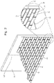
Fig. 1 is an exploded perspective view of an embodiment of the invention showing the layers; -
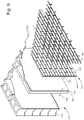
Fig. 2 is a partial perspective view of an embodiment of the invention showing two adjacent panels and highlighting the attachment of the panels to a wall; -
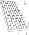
Fig. 3 is a perspective view of an embodiment of the invention showing one panel without the outer veneer layer attached; -
Fig. 4 is perspective view of an embodiment of the invention showing two adjacent panels with the outer veneer layer partially attached and covering the joint between the two adjacent panels; -
Fig. 5 is a perspective view of an embodiment of the invention showing adjacent panels with the outer veneer layer partially attached and covering the joint between two adjacent panels; -
Fig. 6 is an exploded view of an embodiment of the invention showing the layers; -
Fig. 7 is a partially exploded view of an embodiment of the invention showing the middle cement layer adhered to the insulation layer and showing the brick embedded in the substrate forming the two-part veneer layer; -
Fig. 8 is a sectional view of an embodiment of the invention attached to a planar surface; -
Fig. 9 is a sectional view of an embodiment of the invention attached to a plurality of studs; -
Fig. 10 is a sectional view of an embodiment of the invention showing the use of dovetailed brick; -
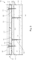
Fig. 11 is a partial front view of an embodiment of the invention showing joints between panels and attachment means; and -
Fig. 12 is a partial front view of an embodiment of the invention showing mortar pointed between the brick and joints between panels and attachment means that have not yet been covered with mortar or other concealing compound; - It is to be understood by a person having ordinary skill in the art that the present discussion is a description of exemplary embodiments only and is not intended as limiting the broader aspects of the present invention. The following example is provided to further illustrate the invention and is not to be construed to unduly limit the scope of the invention.
- Referring to
Figs. 1-5 , the invention is aninsulated wall panel 10 having three layers, 20, 30, and 40. Thepanel 10 provides a finished aesthetic surface to a building, a structural component to a building, and an insulation factor for a building. As such, the installedwall panel 10 includes aninner insulation layer 20, amiddle cement layer 30, and anouter veneer layer 40. Thepanel 10 may be attached to abuilding wall 50. - The
outer veneer layer 40 may include brick (as shown in the drawings) but may also include stone, tile, engineered stone, and/or similar material depending on desired finish effect. Thus, the use of the term "brick" herein is synonymous and inclusive of other veneers thus listed. Theveneer layer 40 is relatively thin and is attached to themiddle cement layer 30 usingmortar 44 or other appropriate material such as a chemical adhesive as best shown inFig. 4 . Each brick (or other material as desired) of theveneer layer 40 is thin and is defined by a perimeter. - The
middle layer 30 provides a substrate to which the brick of theveneer 40 is applied upon installation on abuilding structure 50. Themiddle layer 30 has a plurality of sets ofrelief lines 32. Each set ofrelief lines 32 define a boundary that is just larger than the perimeter of a particular brick of theveneer layer 40 that is to be applied to themiddle layer 30. The relief lines 32 may be formed to the thickness of the desiredgrout 42 spacing between the brick of theveneer layer 40. - The
middle layer 30 is made of a cementatious product with a glass fiber reinforcing material embedded therein. The glass fiber has a high strength and is the principal load-carrying member of themiddle layer 30 while the cement forms a matrix that allows the fibers to retain their desired location and orientation. The resultant product is thin and strong. - In order to form the
middle layer 30, a mold is first constructed into which a slurry of uncured cementatious product of themiddle layer 30 is poured. The mold will have the negatives of therelief lines 32 formed therein. These negatives will appear as small trenches within the mold such that when the cement cures and themiddle layer 30 is removed from the mold, therelief lines 32 will protrude outward from the otherwise generally planarouter surface 34 of the middle layer. Theinner surface 36 of themiddle layer 30 will also be generally planar but will not havesuch relief lines 32. Themiddle layer 30 may remain in the mold while curing. Curing time is dependent upon the thickness, particulars of the mix design, and the environment in which the cement is being cured. Preferably, themiddle cement layer 30 is cured in a chamber. - Once cured, the
middle layer 30 is then placed in a fixture that allows theinner insulation layer 20 to be applied and attached to theinner surface 36 of themiddle layer 30. Theinner insulation layer 20 is a rigid pour foam that is formed from a two part Class I rated urethane. The foam is non-CFC and non-HCFC. The foam is applied to theinner surface 36 of themiddle layer 30 using a machine calibrated to deliver proper and consistent component mix. Thefinished urethane material 20 will have an in place density of approximately 2.2 pounds per cubic foot. Thefoam 20 adheres to themiddle layer 30 such that the machine delivery and mixing of the components provides for a complete bond between themiddle layer 30 andinner insulation layer 20. Thus, there are no adhesives or other chemical bonding required to achieve the strength of the finalinsulated panel 10. Theinner insulation layer 20 may be one inch thick or up to three inches thick or greater depending on the level of insulation desired for a particular application. - Alternatively, rather than being poured, the
middle layer 30 may be press-molded, extruded, vibration cast, sprayed, or slip formed. If, in alternate embodiments, attachment points or other items are incorporated into the structure they are placed in the mold prior to the injection of the urethane. - Once the cement and urethane foam of the respective middle 30 and inner 20 layers has cured, the
panel 10 is in condition for application to abuilding 50. As shown inFig. 2 , thepanels 10 are screwed withscrews 52 to thewall 50 or other structural element of a building. End pieces, headers, and other trim pieces, having been similarly manufactured, are likewise attached to the building. Theseams 22 between the respective panels and trim pieces are sealed with a sealing compound, such as Laticrete® Air and Water Barrier. Next, as shown inFig. 4 , an adhesive such asmortar 44 is applied to the outer surface of themiddle layer 30. Next, the brick of theveneer layer 40 are applied on top of the adhesive 44 and between the relief lines 32. The brick of theveneer 40 are applied to overlap 38 theseams 22 in thepanels 10. This overlapping 38 of the seams is best shown inFigs. 4 and5 . Finally, agrout 42 or other material is applied between the gaps in the brick of theveneer 40. - Referring to
Figs. 6-12 , the invention includes anembodiment 100 utilizing a two-part veneer layer 140. The top part of the veneer layer maybrick 146 as shown. However, the invention contemplates that the concrete, tile, stone, wood, plastic, vinyl, and other materials may be utilized. As used herein, unless otherwise specified, the term "brick" will include all other such materials. - In addition to the two-
part veneer layer 140, the invention may utilize amiddle layer 130. Thismiddle layer 130 may be formed from cement or from Magnesium Oxide or from another composite material. Preferably an insulatinglayer 120 is adhered to themiddle layer 120. Theinner insulation layer 120 is preferably a rigid pour foam that is formed from a two part Class I rated urethane. - The
brick 146 is embedded in asubstrate 144. Thissubstrate 144 may be a polyurethane or other plastic, cement, glass fiber reinforced concrete (GFRC), ceramic, or other composite liquid product. The two part layer is formed by having thebrick 146 positioned in a mold according to desired pattern. Thebrick 146 may be coated with wax or other protective coating. Sand may be utilized as a release agent. Thesubstrate 144 is then poured into the mold and surrounds a lower portion of thebrick 146, thereby embedding thebrick 146 in thesubstrate 144 as the substrate hardens. Thebrick 146 may have a smooth lower surface or may have notches which may bedovetail notches 145 as shown inFig. 10 . - Importantly, especially for exterior application, the mold (not shown) includes a plurality of parallel grooves which, when filled with the
substrate 144form ridges 148 in thesubstrate 144. Theseridges 148 may be seen in the assembled sectional views ofFigs. 8 ,9 , and10 . Between each ridge is a void 149 which forms a channel through which moisture, water, and other fluids may pass between thesubstrate 144 and themiddle cement layer 130. Such fluid may exit through weep holes (not shown). For interior application, nosuch void 149 may be necessary and thesubstrate layer 144 may not have the ridges and may be directly attached to themiddle layer 130. Likewise, for interior application, themiddle layer 130 and theinsulation layer 120 may not be used and the substrate may be adhered directly to an underlying construction element such as stud walls. - In practice, the two-
part veneer layer 140 may be supplied to building contractors as one element and the combination of themiddle layer 130 andinsulation layer 120 may be supplied to building contractors as a second element. Thesecond element screws 152 to ablock wall 150 as shown inFig. 6 orstuds 151 as shown inFig. 9 . Thefirst element 140 may be attached to thefirst element second element mortar 142 may be pointed into the voids between thebrick 146. This grout/mortar 142 may conceal screw heads/holes as shown inFig. 9 . Different grout/mortar joints are possible including raked, grapevine, extruded, concave, V, struck, flush, weathered, struck, and convex. - Alternatively, the
substrate 144 may additionally comprise a sand additive which mimics the appearance of grout. In this embodiment, no additional grout/mortar needs to be added following installation of the top veneer layer except that a small amount of grout/mortar or an equivalent matching concealer such as caulk may be added to conceal screw/attachment heads and/or joints between panels. - The above description has contemplated use in a wall system for either exterior or interior use. However the
invention 100 contemplates use both in ceiling applications (not shown) and in paving and flooring applications (not shown). As shown inFigs. 11 and12 , the joints between panels of the top two-part veneer layer 140 may be staggered to form an interlocking pattern. It is contemplated that panels of theinvention 100 may be cut as needed in a particular application. Corners, reliefs, window edging, keystones, and starter courses are also contemplated under the same methods as discussed above. - A
wall panel system - Protection may also be sought for a wall panel according to one of the following clauses:
- 1. A wall panel comprising:
- a poured substrate selected from the group consisting of polyurethane and plastic; and
- a plurality of aesthetic elements, embedded in and bonded to the poured substrate;
- wherein the aesthetic elements are selected from the group consisting of brick, ceramic tile, porcelain tile, natural stone, engineered stone, wood, ceramic, plastic, and vinyl;
- wherein a finished surface of the aesthetic elements extends above a top surface of the poured substrate; and
- wherein each one of the aesthetic elements is in spaced-apart relation to another one of the aesthetic elements.
- 2. The wall panel of Clause 1 further comprising
- a middle layer having a first side which is attached to a rear surface of the poured substrate; and
- an insulation layer having a first side chemically bonded to a second side of the middle layer;
- wherein the insulation layer comprises a two part rigid urethane pour foam; and
- wherein the insulation layer is chemically bonded to the middle layer during a pour.
- 3. The wall panel of Clause 2 wherein the middle layer is magnesium oxide.
- 4. The wall panel of Clause 2 wherein the middle layer is fiber reinforced cement.
- 5. The wall panel of Clause 3 wherein the middle layer is attached to the poured substrate using an attachment selected from the group consisting of: screws, nails, bolts, welds, construction adhesive, rivets, and clasps.
- 6. The wall panel of Clause 3 wherein the wall panel is attached to a building structure using an attachment selected form the group consisting of: screws, nails, bolts, welds, construction adhesive, rivets, and clasps.
- 7. The wall panel of Clause 1 wherein the poured substrate further comprises sand causing the top surface of the poured substrate to have an appearance of mortar.
- 8. The wall panel of Clause 7 further comprising sanded glue for covering imperfections in the top surface of the poured substrate and for causing the top surface of the poured substrate to have an appearance of mortar.
- 9. A wall panel comprising:
- a middle layer comprising magnesium oxide and having a first and a second side; and
- a veneer layer attached to the first side of the middle layer;
- wherein the veneer layer is selected from the group consisting of brick, ceramic tile, porcelain tile, natural stone, engineered stone, wood, ceramic, plastic, vinyl, and paint.
- 10. The wall panel of Clause 9 further comprising an insulation layer having a first side chemically bonded to a second side of the middle layer, wherein the insulation layer comprises a two part rigid urethane pour foam and wherein the insulation layer is chemically bonded to the middle layer during a pour.
- 11. A wall panel comprising:
- a middle layer comprising magnesium oxide and having a first and a second side;
- a veneer layer attached to the first side of the middle layer; and
- an insulation layer having a first side chemically bonded to a second side of the middle layer;
- wherein the insulation layer comprises a two part rigid urethane pour foam; and
- wherein the insulation layer is chemically bonded to the middle layer during a pour.
- 12. The wall panel of Clause 11 wherein the wall panel is attached to a building structure using an attachment selected form the group consisting of: screws, nails, bolts, welds, construction adhesive, rivets, and clasps.
- 13. The wall panel of Clause 11 wherein the veneer layer further comprises a plurality of aesthetic elements and a poured substrate selected from the group consisting of polyurethane and plastic, wherein a finished surface of the aesthetic elements extends above a top surface of the poured substrate, and wherein each one of the aesthetic elements is in spaced-apart relation to another one of the aesthetic elements.
- 14. The wall panel of Clause 13 wherein the plurality of aesthetic elements is selected from the group consisting of brick, ceramic tile, porcelain tile, natural stone, engineered stone, wood, ceramic, plastic, vinyl, and paint.
- 15. The wall panel of Clause 13 wherein the poured substrate further comprises sand causing the top surface of the poured substrate to have an appearance of mortar.
Claims (13)
- A wall panel comprising:a middle layer comprising magnesium oxide and having a first and a second side the middle layer comprising a glass fiber reinforcing material embedded therein; andan insulation layer bonded to the second side of the middle layer.
- The wall panel of Claim 1 wherein a complete bond is provided between the middle layer and inner insulation layer and/or wherein the insulation layer is chemically bonded to the middle layer.
- The wall panel of Claim 1 wherein the wall panel further comprises a veneer layer attached to the first side of the middle layer.
- The wall panel of Claim 1 wherein the veneer layer comprises a the plurality of aesthetic elements selected from the group consisting of brick, ceramic tile, porcelain tile, natural stone, engineered stone, wood, ceramic, plastic, vinyl, and paint.
- The wall panel of Claim 3 wherein the veneer layer further comprises a plurality of aesthetic elements and a poured substrate selected from the group consisting of polyurethane and plastic, wherein a finished surface of the aesthetic elements extends above a top surface of the poured substrate, and wherein each one of the aesthetic elements is in spaced-apart relation to another one of the aesthetic elements.
- The wall panel of Claim 3 wherein the veneer layer comprises a the plurality of aesthetic elements selected from the group consisting of brick, ceramic tile, porcelain tile, natural stone, engineered stone, wood, ceramic, plastic, vinyl, and paint.
- The wall panel of Claim 5 wherein the poured substrate further comprises sand causing the top surface of the poured substrate to have an appearance of mortar.
- The wall panel of Claim 1 wherein the inner insulation layer includes a rigid pour foam, preferably a two part rigid pour urethane foam.
- The wall panel of Claim 1 wherein the inner insulation layer is one inch and up to or greater than three inches thick, the insulation layer preferably being a foam layer of uniform thickness.
- The wall panel of Claim 1 wherein the insulation may provide the panels with an insulation factor of R7 to R21 or greater depending on various factors of design.
- The wall panel of Claim 1 wherein the wall panel is attached to a building structure using an attachment selected form the group consisting of: screws, nails, bolts, welds, construction adhesive, rivets, and clasps
- Wall panel system for either exterior or interior use comprising a plurality of wall panels according to one or more of claims 1-11.
- The wall panel system according to claim 12 wherein seams between the wall panels are sealed.
Applications Claiming Priority (3)
| Application Number | Priority Date | Filing Date | Title |
|---|---|---|---|
| US201562245617P | 2015-10-23 | 2015-10-23 | |
| EP16857914.2A EP3365511B1 (en) | 2015-10-23 | 2016-04-29 | Insulated wall panel with plurality of aesthetic facing elements |
| PCT/US2016/029954 WO2017069802A1 (en) | 2015-10-23 | 2016-04-29 | Wall panel |
Related Parent Applications (1)
| Application Number | Title | Priority Date | Filing Date |
|---|---|---|---|
| EP16857914.2A Division EP3365511B1 (en) | 2015-10-23 | 2016-04-29 | Insulated wall panel with plurality of aesthetic facing elements |
Publications (1)
| Publication Number | Publication Date |
|---|---|
| EP4105407A1 true EP4105407A1 (en) | 2022-12-21 |
Family
ID=58557844
Family Applications (3)
| Application Number | Title | Priority Date | Filing Date |
|---|---|---|---|
| EP22188971.0A Pending EP4105406A1 (en) | 2015-10-23 | 2016-04-29 | Multi-layer insulated wall panel |
| EP22189052.8A Pending EP4105407A1 (en) | 2015-10-23 | 2016-04-29 | Insulated fibre reinforced wall panel |
| EP16857914.2A Active EP3365511B1 (en) | 2015-10-23 | 2016-04-29 | Insulated wall panel with plurality of aesthetic facing elements |
Family Applications Before (1)
| Application Number | Title | Priority Date | Filing Date |
|---|---|---|---|
| EP22188971.0A Pending EP4105406A1 (en) | 2015-10-23 | 2016-04-29 | Multi-layer insulated wall panel |
Family Applications After (1)
| Application Number | Title | Priority Date | Filing Date |
|---|---|---|---|
| EP16857914.2A Active EP3365511B1 (en) | 2015-10-23 | 2016-04-29 | Insulated wall panel with plurality of aesthetic facing elements |
Country Status (5)
| Country | Link |
|---|---|
| EP (3) | EP4105406A1 (en) |
| AU (1) | AU2016342075B2 (en) |
| CA (1) | CA3010868C (en) |
| ES (1) | ES2925889T3 (en) |
| WO (1) | WO2017069802A1 (en) |
Families Citing this family (4)
| Publication number | Priority date | Publication date | Assignee | Title |
|---|---|---|---|---|
| GB2579769B (en) * | 2018-10-25 | 2023-08-23 | Tectonic Facades Ltd | Cladding panel |
| AU2019463322A1 (en) * | 2019-08-23 | 2022-02-17 | Skonto Concrete Cladding, Sia | A brick slip panel and a method of manufacture a brick slip panel |
| EP3816364A1 (en) * | 2019-10-29 | 2021-05-05 | Isosystems AG | Fire resistant modular prefabricated cladding panel |
| BE1028120A9 (en) * | 2020-03-03 | 2021-10-13 | Dimitri Anna A Vervaet | Method for cladding a wall with brick slips and impression mold and brick slips applied therein. |
Citations (7)
| Publication number | Priority date | Publication date | Assignee | Title |
|---|---|---|---|---|
| US6240691B1 (en) * | 1996-06-21 | 2001-06-05 | Pan-Brick Inc. | Prefabricated composite building panel with fire barrier |
| US20100297411A1 (en) * | 2009-05-21 | 2010-11-25 | Cheng-Chung Tsai | Laminated Board |
| AU2010101323A4 (en) * | 2010-11-25 | 2011-01-06 | Guangning Yao | Environment protection type detachable wall panel |
| US20110268916A1 (en) * | 2010-04-30 | 2011-11-03 | Pardue Jr Johnny Roger | Double Skin Composite Hybrid Structural Insulated Panel |
| US20140069050A1 (en) * | 2009-06-26 | 2014-03-13 | Joel W. Bolin | Composite panels and methods and apparatus for manufacture and installtion thereof |
| US20140083040A1 (en) * | 2012-09-27 | 2014-03-27 | Max Life, LLC | Insulated wall panel |
| US20150052838A1 (en) * | 2013-08-21 | 2015-02-26 | MagBoard, LLC | Laminate building materials and methods of making and installing the same |
Family Cites Families (3)
| Publication number | Priority date | Publication date | Assignee | Title |
|---|---|---|---|---|
| GB1202701A (en) * | 1966-09-02 | 1970-08-19 | Kalco Holdings Ltd | Prefabricated building panel |
| US3868801A (en) * | 1970-03-18 | 1975-03-04 | Gershen Weiner | Building panel |
| NL7316287A (en) * | 1973-12-07 | 1975-05-30 | Mallinson & Mott Ltd | BUILDING PANEL AND THE MANUFACTURE OF A BUILDING PANEL. |
-
2016
- 2016-04-29 EP EP22188971.0A patent/EP4105406A1/en active Pending
- 2016-04-29 ES ES16857914T patent/ES2925889T3/en active Active
- 2016-04-29 EP EP22189052.8A patent/EP4105407A1/en active Pending
- 2016-04-29 CA CA3010868A patent/CA3010868C/en active Active
- 2016-04-29 EP EP16857914.2A patent/EP3365511B1/en active Active
- 2016-04-29 AU AU2016342075A patent/AU2016342075B2/en active Active
- 2016-04-29 WO PCT/US2016/029954 patent/WO2017069802A1/en unknown
Patent Citations (7)
| Publication number | Priority date | Publication date | Assignee | Title |
|---|---|---|---|---|
| US6240691B1 (en) * | 1996-06-21 | 2001-06-05 | Pan-Brick Inc. | Prefabricated composite building panel with fire barrier |
| US20100297411A1 (en) * | 2009-05-21 | 2010-11-25 | Cheng-Chung Tsai | Laminated Board |
| US20140069050A1 (en) * | 2009-06-26 | 2014-03-13 | Joel W. Bolin | Composite panels and methods and apparatus for manufacture and installtion thereof |
| US20110268916A1 (en) * | 2010-04-30 | 2011-11-03 | Pardue Jr Johnny Roger | Double Skin Composite Hybrid Structural Insulated Panel |
| AU2010101323A4 (en) * | 2010-11-25 | 2011-01-06 | Guangning Yao | Environment protection type detachable wall panel |
| US20140083040A1 (en) * | 2012-09-27 | 2014-03-27 | Max Life, LLC | Insulated wall panel |
| US20150052838A1 (en) * | 2013-08-21 | 2015-02-26 | MagBoard, LLC | Laminate building materials and methods of making and installing the same |
Also Published As
| Publication number | Publication date |
|---|---|
| AU2016342075A1 (en) | 2018-04-26 |
| AU2016342075B2 (en) | 2019-02-21 |
| EP3365511A4 (en) | 2019-05-22 |
| WO2017069802A1 (en) | 2017-04-27 |
| EP3365511B1 (en) | 2022-08-10 |
| ES2925889T3 (en) | 2022-10-20 |
| CA3010868A1 (en) | 2017-04-27 |
| CA3010868C (en) | 2019-07-23 |
| EP4105406A1 (en) | 2022-12-21 |
| EP3365511A1 (en) | 2018-08-29 |
Similar Documents
| Publication | Publication Date | Title |
|---|---|---|
| US10858842B2 (en) | Wall panel | |
| US9957722B2 (en) | Insulated wall panel | |
| US20170268232A1 (en) | Integral Composite Shuttering Panel and Monolithic Wall Building System | |
| US20100071292A1 (en) | System and method for sealing joints between exterior wall panels | |
| US7748183B2 (en) | System, methods and compositions for attaching paneling to a building surface | |
| WO2011135495A2 (en) | Np-eifs non-permissive exterior insulation and finish systems concept technology and details | |
| EP3365511B1 (en) | Insulated wall panel with plurality of aesthetic facing elements | |
| US20080155938A1 (en) | Fiber reinforced concrete stone panel system | |
| EP3314066A1 (en) | Modified osb board and its use in walls for house building systems | |
| US7521114B2 (en) | Vandalism-resistant insulating panel for building exteriors and building having vandalism-resistant thermally insulative walls | |
| AU2010100010A4 (en) | Wall lining | |
| US20140023833A1 (en) | Two-layer tape and joint system for exterior building panels | |
| JPH08193409A (en) | Fiber-reinforced plastic panel, its joint body, and incombustible, composite, fiber-reinforced plastic panel | |
| EP3059354B1 (en) | Structural module and method for mounting structural modules | |
| AU2010100181A4 (en) | Wall lining panel | |
| JPH1088696A (en) | Waterproof board | |
| JP2004204636A (en) | Construction method of heat insulator | |
| JP2000145008A (en) | Construction panel, fence using same construction panel, outer wall structure, outer construction structure for planting trees, and road surface structure | |
| AU2010200032A1 (en) | Wall lining |
Legal Events
| Date | Code | Title | Description |
|---|---|---|---|
| PUAI | Public reference made under article 153(3) epc to a published international application that has entered the european phase |
Free format text: ORIGINAL CODE: 0009012 |
|
| STAA | Information on the status of an ep patent application or granted ep patent |
Free format text: STATUS: THE APPLICATION HAS BEEN PUBLISHED |
|
| AC | Divisional application: reference to earlier application |
Ref document number: 3365511 Country of ref document: EP Kind code of ref document: P |
|
| AK | Designated contracting states |
Kind code of ref document: A1 Designated state(s): AL AT BE BG CH CY CZ DE DK EE ES FI FR GB GR HR HU IE IS IT LI LT LU LV MC MK MT NL NO PL PT RO RS SE SI SK SM TR |
|
| STAA | Information on the status of an ep patent application or granted ep patent |
Free format text: STATUS: REQUEST FOR EXAMINATION WAS MADE |
|
| P01 | Opt-out of the competence of the unified patent court (upc) registered |
Effective date: 20230525 |
|
| 17P | Request for examination filed |
Effective date: 20230620 |
|
| RBV | Designated contracting states (corrected) |
Designated state(s): AL AT BE BG CH CY CZ DE DK EE ES FI FR GB GR HR HU IE IS IT LI LT LU LV MC MK MT NL NO PL PT RO RS SE SI SK SM TR |
|
| STAA | Information on the status of an ep patent application or granted ep patent |
Free format text: STATUS: EXAMINATION IS IN PROGRESS |
|
| 17Q | First examination report despatched |
Effective date: 20230829 |