EP4104778A1 - Apparatus, system and method for identifying subintimal path of a flexible elongated device - Google Patents
Apparatus, system and method for identifying subintimal path of a flexible elongated device Download PDFInfo
- Publication number
- EP4104778A1 EP4104778A1 EP21179223.9A EP21179223A EP4104778A1 EP 4104778 A1 EP4104778 A1 EP 4104778A1 EP 21179223 A EP21179223 A EP 21179223A EP 4104778 A1 EP4104778 A1 EP 4104778A1
- Authority
- EP
- European Patent Office
- Prior art keywords
- curvature
- subintimal
- elongated device
- path
- shape
- Prior art date
- Legal status (The legal status is an assumption and is not a legal conclusion. Google has not performed a legal analysis and makes no representation as to the accuracy of the status listed.)
- Withdrawn
Links
Images



Classifications
-
- A—HUMAN NECESSITIES
- A61—MEDICAL OR VETERINARY SCIENCE; HYGIENE
- A61B—DIAGNOSIS; SURGERY; IDENTIFICATION
- A61B34/00—Computer-aided surgery; Manipulators or robots specially adapted for use in surgery
- A61B34/10—Computer-aided planning, simulation or modelling of surgical operations
-
- A—HUMAN NECESSITIES
- A61—MEDICAL OR VETERINARY SCIENCE; HYGIENE
- A61M—DEVICES FOR INTRODUCING MEDIA INTO, OR ONTO, THE BODY; DEVICES FOR TRANSDUCING BODY MEDIA OR FOR TAKING MEDIA FROM THE BODY; DEVICES FOR PRODUCING OR ENDING SLEEP OR STUPOR
- A61M25/00—Catheters; Hollow probes
- A61M25/01—Introducing, guiding, advancing, emplacing or holding catheters
- A61M25/09—Guide wires
-
- A—HUMAN NECESSITIES
- A61—MEDICAL OR VETERINARY SCIENCE; HYGIENE
- A61B—DIAGNOSIS; SURGERY; IDENTIFICATION
- A61B17/00—Surgical instruments, devices or methods
- A61B2017/00017—Electrical control of surgical instruments
- A61B2017/00115—Electrical control of surgical instruments with audible or visual output
- A61B2017/00119—Electrical control of surgical instruments with audible or visual output alarm; indicating an abnormal situation
-
- A—HUMAN NECESSITIES
- A61—MEDICAL OR VETERINARY SCIENCE; HYGIENE
- A61B—DIAGNOSIS; SURGERY; IDENTIFICATION
- A61B34/00—Computer-aided surgery; Manipulators or robots specially adapted for use in surgery
- A61B34/10—Computer-aided planning, simulation or modelling of surgical operations
- A61B2034/101—Computer-aided simulation of surgical operations
- A61B2034/102—Modelling of surgical devices, implants or prosthesis
- A61B2034/104—Modelling the effect of the tool, e.g. the effect of an implanted prosthesis or for predicting the effect of ablation or burring
-
- A—HUMAN NECESSITIES
- A61—MEDICAL OR VETERINARY SCIENCE; HYGIENE
- A61B—DIAGNOSIS; SURGERY; IDENTIFICATION
- A61B34/00—Computer-aided surgery; Manipulators or robots specially adapted for use in surgery
- A61B34/10—Computer-aided planning, simulation or modelling of surgical operations
- A61B2034/107—Visualisation of planned trajectories or target regions
-
- A—HUMAN NECESSITIES
- A61—MEDICAL OR VETERINARY SCIENCE; HYGIENE
- A61B—DIAGNOSIS; SURGERY; IDENTIFICATION
- A61B34/00—Computer-aided surgery; Manipulators or robots specially adapted for use in surgery
- A61B34/20—Surgical navigation systems; Devices for tracking or guiding surgical instruments, e.g. for frameless stereotaxis
- A61B2034/2046—Tracking techniques
- A61B2034/2051—Electromagnetic tracking systems
-
- A—HUMAN NECESSITIES
- A61—MEDICAL OR VETERINARY SCIENCE; HYGIENE
- A61B—DIAGNOSIS; SURGERY; IDENTIFICATION
- A61B34/00—Computer-aided surgery; Manipulators or robots specially adapted for use in surgery
- A61B34/20—Surgical navigation systems; Devices for tracking or guiding surgical instruments, e.g. for frameless stereotaxis
- A61B2034/2046—Tracking techniques
- A61B2034/2061—Tracking techniques using shape-sensors, e.g. fiber shape sensors with Bragg gratings
-
- A—HUMAN NECESSITIES
- A61—MEDICAL OR VETERINARY SCIENCE; HYGIENE
- A61M—DEVICES FOR INTRODUCING MEDIA INTO, OR ONTO, THE BODY; DEVICES FOR TRANSDUCING BODY MEDIA OR FOR TAKING MEDIA FROM THE BODY; DEVICES FOR PRODUCING OR ENDING SLEEP OR STUPOR
- A61M25/00—Catheters; Hollow probes
- A61M25/01—Introducing, guiding, advancing, emplacing or holding catheters
- A61M25/0194—Tunnelling catheters
- A61M2025/0197—Tunnelling catheters for creating an artificial passage within the body, e.g. in order to go around occlusions
-
- A—HUMAN NECESSITIES
- A61—MEDICAL OR VETERINARY SCIENCE; HYGIENE
- A61M—DEVICES FOR INTRODUCING MEDIA INTO, OR ONTO, THE BODY; DEVICES FOR TRANSDUCING BODY MEDIA OR FOR TAKING MEDIA FROM THE BODY; DEVICES FOR PRODUCING OR ENDING SLEEP OR STUPOR
- A61M25/00—Catheters; Hollow probes
- A61M25/01—Introducing, guiding, advancing, emplacing or holding catheters
- A61M25/09—Guide wires
- A61M2025/09175—Guide wires having specific characteristics at the distal tip
- A61M2025/09183—Guide wires having specific characteristics at the distal tip having tools at the distal tip
Definitions
- the present invention relates to an apparatus, method and system for identifying subintimal path of a flexible elongated device through a lumen.
- the invention further relates to a corresponding computer program.
- the invention is useful in the field of endovascular interventions, in particular for treatment of chronic total occlusions.
- Chronic total occlusions (CTO) in arteries can be treated by crossing the CTO with a guidewire and subsequently ballooning the occluded area. Additionally, a stent can be placed.
- the CTO can be crossed intraluminal or via the subintimal. Physicians are often not exactly aware of how they have crossed the CTO with the guidewire. This may have critical clinical implications. In particular, atherectomy, i.e. debulking of the material in the occlusion, can only be performed if the crossing of the CTO is intraluminal. Thus, there is a need for a detector detecting if the guidewire undergoes subintimal path through the vessel.
- US 10 267 624 D2 discloses a system for reconstructing a trajectory of an optical fiber.
- the system comprises an optical fiber to be inserted into an object, wherein the optical fiber has a length and at least one bending sensor unit arranged along its length.
- the system also comprises a measurement device configured to measure insertion length increments of the optical fiber and an interrogation device configured to detect optical feedback signals from the at least one bending sensor unit.
- the system further comprises a processor device configured to reconstruct the trajectory of the optical fiber along its inserted length using data pairs which are based on measured insertion length increments and detected optical feedback signals assigned thereto.
- an apparatus for identifying subintimal path of a flexible elongated device through a lumen comprising:
- the present invention is based on the idea that a flexible elongated device which is navigated along a subintimal path should exhibit a shape which significantly differs from the shape of the flexible elongated device when navigated along an intraluminal path.
- the shape of the flexible elongated device navigated along a subintimal path may be considered to be a spiraled or helical shape.
- a perfect or ideal helix has a constant curvature along the helix.
- determining the curvature profile of the elongated device in one or more shape segments of the elongated device is advantageous for detecting subintimal path.
- the shape of the device will not be a perfect helix in the subintimal region due to inaccuracy in e.g. the shape sensing process, shape- and/or position-related data imprecision and the difference of the actual navigation from a helix so that the actual shape of the elongated device in the subintimal region will deviate from an ideal helix shape. Therefore, the present invention proposes to analyze the curvature profile to identify one or more sections in the curvature profile which may be candidates for a subintimal path of the elongated device.
- curvature values should be observed in the curvature profile which are recognizably elevated in comparison to an intraluminal region of the path of the elongated device.
- curvature is zero or low.
- the curvature profile is analyzed to determine whether the elongated device exhibits an elevated curvature in one or more sections to identify an intraluminal path of the device and to output an information, if a subintimal path has been identified.
- the present invention thus enables quick and accurate detection of the occurrence of subintimal navigation of a flexible elongated device with low amount of computation.
- the invention is beneficial in endovascular interventions, in particular in treating CTO.
- the instructions comprising:
- the curvature profile is measured, e.g. by a shape sensing modality, and analyzed by the processor to determine at least one section in which the curvature profile is above a first curvature threshold level defined as representative of a deformation of the elongated device which may be due to an obstacle in the path of the elongated device.
- a curvature strength parameter is then determined from curvature values in this section.
- the curvature strength parameter may be an indicator for the amount of deviation of the shape from a straight shape.
- the curvature strength parameter may be an indicator whether the curvature profile in the at least one section resembles a curvature profile of a helical or spiraled shape. If the curvature strength parameter is above a subintimal threshold level defined as a representative indicating subintimal path, the path of the elongated device through the lumen is identified as subintimal path. The physician is warned if subintimal path of the elongated device has been identified.
- a plurality of shape runs may be performed, and the measured curvature profiles in the shape runs may be analyzed as described before to monitor whether subintimal passage occurs during navigation.
- the instructions comprising: a curvature classifier configured with curvature-related parameters to receive shape- and/or position-related data of the elongated device and to output a classification of curvatures along said at least one segment, wherein the classifier is configured to output at least one classification of curvature associated with a subintimal path, wherein the processor in communication with the memory is configured to apply the curvature classifier to shape- and/or position-related data measured along said at least one segment of the elongated device (10) to output said information of a subintimal path if a subintimal path class has been found by the classifier.
- the invention makes use of artificial intelligence, by collecting large sets of data, annotating the data, and using the data to train a deep learning method or another machine-learning method, such as decision trees, random forests, support vector machines, or neural networks.
- An AI-based algorithm can be used to classify a shape in one of pre-determined classes, such as the elongated device tip in a normal region, tip entering the subintimal region, tip passed the subintimal region, and so on, without estimating specific curvature parameters.
- the input to such an AI-based algorithm can be curvature profile of the elongated device, or shape of the elongated device as a set of 3D point coordinates, or a combination of the two so that AI-based algorithm can pick additional features to curvature.
- the instructions may comprise determining the curvature strength parameter as the sum of curvature values in the at least one section of the curvature profile.
- the sum of the curvature values of the curvature profile in the region of interest is then compared with the subintimal threshold level, and if the sum of the curvature values is above the subintimal threshold level, the warning that subintimal path has been identified is output.
- the term "sum” may also include the integral of the curvature profile in the at least one section, in which the curvature profile is above the first curvature threshold level. Summing discrete curvature values is advantageous in terms of computational expenditure.
- the instructions may comprise determining the curvature strength parameter as the mean of curvature values in the at least one section of the curvature profile.
- Computing the mean of the curvature values also is advantageous in terms of computational expenditure.
- the instructions may comprise identifying the at least one section as not indicating subintimal passage, if the maximum curvature value is below a second curvature threshold level higher than the first curvature threshold level. If the maximum curvature value is below the second curvature threshold level, the at least one section can be considered as invalid, and determination of the curvature strength parameter may be omitted for this section. Subjecting the analysis of the curvature profile in the section where the curvature profile is above the first curvature threshold level to a second higher curvature threshold value has the advantage that noisy calculations in this section may be prevented or the curvature profiles exceeding the first threshold for a long time but not achieving a maximum value as high as the second threshold may be discarded.
- the ratio of the second curvature threshold value and the first curvature threshold value may be in a range from 1.5 to 3, e.g. 2.
- the instructions may comprise determining the at least one section by determining crossing points of the curvature profile with the first curvature threshold level. This operation in the analysis of the curvature profile again has the advantage of low computational expenditure.
- Measuring the curvature profile may be limited to one shape segment of the elongated device, wherein in this case it is preferred that the shape segment includes the distal tip of the device, as the occurrence of subintimal path of the flexible elongated device is most expected at the distal tip of the device. Measuring the curvature profile may also be performed along one or more other shape segments between the distal tip and the proximal end. Curvature strength parameters may be computed for each of these shape segments.
- the region to compute the curvature strength parameter can be determined from anatomical information. For instance, on contrast-enhanced X-ray or 3D anatomical data, occlusion regions can be identified. After registering the shape to X-ray and 3D anatomical data, the method according to the invention can be triggered when the flexible elongated device is in the occlusion region identified in the anatomical image data.
- the instructions may comprise determining the distance of the distal end of the at least one section from the distal tip of the elongated device, and to identify the at least one section as the distal tip portion, if the determined distance is lower than a threshold distance.
- the segment is not considered a segment including the distal tip of the device, and the curvature strength in the distal tip segment may be set to zero.
- the instructions may comprise setting at least two different subintimal thresholds, and outputting different warnings according to the different subintimal thresholds. It is advantageous to provide a warning scheme which takes into account of the severity of the deviation of the passage of the elongated device from intraluminal passage. For example, multiple warning levels may be defined, and depending on above which of these levels the curvature strength parameter is, a different warning is output. For example, a color-coded warning may be provided, such as yellow, orange, light red, and dark red, wherein this order of colors indicates increasing severity of the deviation of the passage from intraluminal path.
- the instructions may comprise setting a time limit and outputting the warning if the curvature profile representative of subintimal path is detected for a time period exceeding the time limit.
- outputting a warning is not only subject to e.g. the crossing of the subintimal threshold, but also to a timing constraint, i.e. the warning is only output when both subintimal threshold and time limit are exceeded.
- This embodiment takes into account that subintimal passage may only occur for a short time period. e.g. below 1 or 2 seconds, and thereafter the elongated device undergoes an intraluminal path again. Thus, warning may be avoided if a warning is not necessary.
- time limits for the different subintimal thresholds may be provided, wherein the time limits may be adapted to the warning levels. For example, for a low warning level, the time limit may be set higher than for a high warning level.
- the warning may be output as haptic, audio, visual or textual warning.
- the warning may be visualized on a display and/or reproduced by a loudspeaker.
- the apparatus is also configured to display the shape of the elongated device, e.g. on a monitor, it can also be provided that the visualized shape in the region of interest that caused a high curvature strength parameter may change the color, for example from green (intraluminal passage) to red (subintimal passage).
- the apparatus may comprise an optical shape sensing modality comprising an optical interrogation modality configured to optically interrogate an optical fiber comprised by the elongated device and to receive optical feedback from the optical fiber.
- 3D shape sensing can also be used in the present invention.
- electromagnetic tracking systems may be used.
- a system comprising an elongated flexible device and an apparatus according to the first aspect.
- the flexible elongated device may be a guidewire or catheter.
- a computer-implemented method of automatically identifying subintimal passage of a flexible elongated device through a lumen comprising:
- a computer program comprising program code means for causing a computer to carry out the steps of the method according to the third aspect when said computer program is carried out on a computer.
- a non-transitory computer-readable recording medium that stores therein the computer program is encompassed by the present disclosure.
- Fig. 1 shows a sketch for illustrating intraluminal and subintimal path of a flexible elongated device 10 through a lumen of a vessel V.
- the vessel V may be an artery, for example.
- the vessel may be subject to a chronic total occlusion CTO which narrows the lumen in the vessel V inside the vessel wall VW.
- a CTO can be treated by crossing the CTO with the elongated device 10, which may be a guidewire GW. After crossing the CTO with the guidewire GW, the occluded area may be ballooned. Additionally, a stent (not shown) can be placed.
- the elongated device 10 is navigated through the vessel V, i.e.
- Reference numeral 12 denotes the tip portion of the flexible elongated device 10.
- the elongated device 10 may undergo an intraluminal path or a subintimal path.
- the elongated device 10 is shown in solid lines for intraluminal path, and in broken lines for subintimal path.
- the present disclosure provides a computer-implemented method and an apparatus for automatically identify subintimal path of an elongated flexible device like device 10 and to provide a real-time warning about subintimal CTO track so that a physician can adapt the treatment during the surgery and make sure that atherectomy is utilized only when the crossing of the CTO by the elongated device 10 is intraluminal. Furthermore, the disclosure herein may provide a real-time warning about the degree of subintimal CTO track.
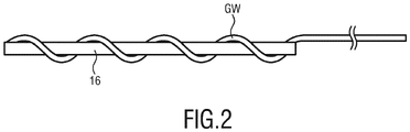
- FIG. 2 A bench test was conducted with an optical shape sensing enabled guidewire GW shown in Fig. 2 .
- the guidewire GW was spiraled around a 3 mm diameter ball pen filler 16 mimicking a 3 mm lumen of a vessel.
- the present teachings are based on the idea that a guidewire, when in the subintimal path, takes a spiraled shape along the subintimal path.
- the spiraling of the guidewire GW around the ball pen filler has been made to mimic the assumed spiraling of a guidewire in the subintimal space.
- the guidewire GW spiraled around the ball pen filler 16 was shape-sensed, in the present case optically shape-sensed.
- Optical shape sensing has been performed with an optical frequency domain reflectometry (OFDR) sensing system.
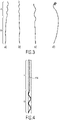
- Figs. 3a) to 3d show reconstructions of the guidewire in different views created by an optical shape sensing viewing software.
- Fig. 3a shows a front view
- Fig. 3b shows a side view
- Fig. 3c shows an enlarged front view
- Fig. 3d shows a view in longitudinal direction of the ball pen filler 16.
- the 3D-reconstruction of the guidewire has a spiraled configuration in a region A where it is spiraled around the ball pen filler 16 which is distinct from the normal straight configuration in region B.
- Fig. 4 shows the visualization of the reconstructed shape of an optical shape sensing enabled guidewire in a real case where the guidewire has undergone subintimal passage through a CTO.
- the guidewire GW has a spiraled configuration in the subintimal region S, and a normal/straight configuration in the intraluminal region I.
- This distinction forms the basis of the present teachings to automatically detect if the guidewire GW is in the intraluminal or subintimal space, or partially in the subintimal and partially in the intraluminal path. According to the present disclosure, transitions from the intraluminal into the subintimal space and vice versa may also be detected.
- the 3D shape of the elongated device 10 in the subintimal path may be in the form of an (imperfect) helix.
- This computational operation however may require a large amount of computation when doing this computation for every shape measurement during navigation of the elongated device 10, and the computation may not always provide a unique solution.
- the shape of the elongated device is not always going to fit to a helix because of shape measurement inaccuracy and the formation of the actual subintimal path. Therefore, the present teachings propose an indirect, but more practical solution that can handle both imperfectness of the shape sensing data and the subintimal passage without a large amount of computation.
- the method according to the present disclosure analyzes the curvature profile obtained from a measurement of the shape of the elongated device 10.
- the reason why curvature is a good candidate for the identification of subintimal path is that the curvature of a perfect cylindrical helix is a constant and with reference to the parameters a and b above, is equal to a / a 2 + b 2 .
- the shape of the elongated device 10 in the subintimal path is expected to be similar to a helix shape, it is consequently to be expected that the 3D shape of the elongated device 10 has a significantly higher curvature in a subintimal path in comparison to an intraluminal path. If the subintimal path results in an ideal helix shape of the elongated device, then a rectangular curvature profile with high constant curvature should be observed. When the tip portion 14 of the device 10 is in the subintimal path, the elevated constant curvature profile occurs at the most distal part of the curvature profile.
- Fig. 5 shows a flow diagram of an embodiment of a computer-implemented method of automatically identifying subintimal path of an elongated device.
- the method 100 comprises a step S102 of measuring a curvature profile along at least one shape segment of the elongated device 10. Measuring the curvature profile may be performed by evaluating shape sensing data obtained from a shape sensing modality, like an optical shape sensing modality or any other source of shape sensing data. Curvatures may be extracted or calculated from the shape sensing data as known to those skilled in the art.
- Fig. 6 shows a diagram of a curvature profile at a distal portion of an elongated device 10, wherein the distal portion is in the subintimal path.
- the x-axis in Fig. 6 shows the sample points (nodes) of the shape sensing data, and the y-axis shows the curvature (in units of reciprocal sample points).
- a sample point 350 is the tip of the elongated device 10.
- the shape sensing data in Fig. 6 were obtained in a real case of an elongated device navigated through a vessel.
- the curvature profile has curvature values from sample points 270-350 which are significantly elevated in comparison to the curvature values of the curvature profile below sample point 270.
- curvature profiles occur at various positions of the device along the subintimal path as shown in Fig. 7 and Fig. 8 .
- the curvature profile of each shape measurement will show elevated curvatures in the subintimal path during navigation of the device 10.
- the curvature values in the region where the curvature values are elevated differ from Fig. 6 to Fig. 7 and from Fig. 7 to Fig. 8 .
- the curvature profile shows a distinct region of high curvature. That is, the distal portion including the tip (sample point 350) of the device 10 is assumed to be in the subintimal path.
- the method 100 proceeds with a step S 104 of determining in the curvature profile at least one section, in which the curvature profile is above a first curvature threshold level.
- the curvature threshold level is defined as representative of a deformation of the elongated device which may be due to an obstacle in the path of the elongated device.
- Fig. 9 shows an embodiment of an implementation of method step S104.
- the first curvature threshold level 20 is preferably set as a low curvature value, e.g. 0.5 as shown in Fig. 9 .
- Determination of the at least one section in which the curvature profile is above the first curvature threshold level may be performed by determining crossing points A and B of the curvature profile with the first curvature threshold level 20. This in turn may be performed by scanning the curvature profile from distal (sample point 350) to proximal (sample point 0) (or vice versa) and finding the locations A and B where the curvature profile passes the level 20.
- the method 100 proceeds to a step S106 of determining from curvature values of the curvature profile in the at least one section in which the curvature profile is above the first curvature threshold level 20 a curvature strength parameter which is indicative of how strong curvature is in the at least one section A-B.
- the curvature strength parameter is determined as the sum of the curvature values in the section A-B of the curvature profile. The operation of summing the curvature values in the section A-B is illustrated by vertical lines 22 in Fig. 10 .
- the curvature strength parameter may be determined as the mean of the curvature values in the section A-B of the curvature profile.
- the method 100 comprises a step S108 of identifying the path of the elongated device 10 through the lumen as subintimal path, if the curvature strength parameter determined beforehand is above a subtintimal threshold.
- the subintimal threshold may be a value which can be set much larger, e.g. by an order of magnitude, than the first curvature threshold level 20.
- the method 100 further proceeds to step S110 of outputting a warning if subintimal passage has been identified.
- the warning may be output as haptic, audio, visual or textual warning.
- the method 100 may further comprise, for example before step S106, and after step S104, a step of identifying the section A-B as not indicating subintimal passage, if the maximum curvature value in the section A-B is below a second curvature threshold level higher than the first curvature threshold level 20.
- a second curvature threshold level 24 is indicated.
- the second curvature threshold level 24 may be in a range from 1.5-2.5, e.g. 2, times the first curvature threshold level 20.
- the second curvature threshold level 24 is set to 0.1, so twice the first curvature threshold level. This step may advantageously avoid noisy calculations or may advantageously be used to discard the curvature profiles exceeding the first threshold for a long time but not achieving a maximum value as high as the second threshold.
- distal shape segment including the tip of the elongated device 10 While in the above description only the distal shape segment including the tip of the elongated device 10 has been considered, other shape segments of the elongated device 10 between the distal and the proximal end may be considered. However, performing the method for the distal shape segment of the elongated device 10 is of most importance and advantage.
- the method 100 may further comprise, after step S104, determining the distance of the distal end A of the section A-B from the distal tip 14 of the elongated device 10, and to identify the section A-B as the distal tip portion, if the determined distance is lower than a threshold distance. Otherwise, the segment under consideration is not considered a distal shape segment, and the distal shape segment curvature strength parameter may be set to zero, if the method of identifying subintimal path is only applied or interesting for the distal tip portion of the device 10.
- a curvature strength parameter can be determined, or multiple curvature strength parameters may be determined in case that for example non-distal shape segments shall be evaluated as well, and decisions based on these curvature strength parameter(s) can be made.
- Fig. 12 and Fig. 13 show the distribution of these curvature strength parameters for a large number of shape runs.
- Fig. 12 shows the determined curvature strength parameters for a number of more than 10,000 shape measurements (shape runs) recorded without subintimal path and with subintimal path in Fig. 13 , respectively.
- the curvature strength parameters have been computed without requiring that the maximum curvature values in section A-B are above the second curvature threshold level 24 ( Fig.
- the curvature strength parameter for each shape run show subintimal passage after shape run #10,000 and a short attempt around shape run #3,500.
- the values beginning from shape run 10,000 are mostly above 6 indicating subintimal path of the elongated device 10, whereas the curvature strength parameter is below 4 in the region of navigation, indicating intraluminal path.
- warning levels may be predetermined, such as 4, 6, 8, 10, and when the curvature strength parameter is above one of these levels, a color-coded warning may be provided, such as yellow, orange, light red, and dark red.
- a color-coded warning may be provided, such as yellow, orange, light red, and dark red.
- each time limit may be assigned to one of the different subintimal thresholds. For example, the time limit of 2 seconds for curvature strength parameters below 6 and 1 second for values above 6. The warning is provided only when both amplitude and timing constraints are satisfied.
- the color of the visualized shape in the region-of-interest that caused high curvature strength parameter may be changed, for example from green to red.
- the curvature related parameters described above can be estimated with supervised machine learning and optimization techniques. The same method as described above may be used. However, the curvature-related parameters indicated above are determined optimally by using an annotated set of shapes.
- the annotated shape set may include the following for each shape in the set:
- the values of the curvature-related parameters can be determined to maximize the detection of shape segments with elevated curvature. Because only two parameters are to be estimated, a full search of the combinations can be made and the accuracy can be evaluated by using the first label of the annotated dataset above, and the combination of values resulting in the best accuracy can be picked.
- the optimal threshold can be calculated separately for both using the sum or the mean of the curvature in the determined shape segment. In case another method to measure the curvature strength is conceived, the optimal threshold can be re-calculated by using that method.
- subintimal passage likelihood is used to indicate the degree that a device passes through the CTO subintimally. In the previous embodiments, this was determined as 0/1 by comparing the curvature strength to a threshold value. In the AI-based method, this can be calculated as a continuous value between 0 and 1 without the explicit use of curvature strength. Thus, subintimal passage likelihood is a more general term to describe this situation.
- AI-based shape classification can be used as follows.
- a whole shape, or a part of it, can be classified as subintimal or intraluminal and, in addition to that, a degree can be assigned to it.
- the degree may be indicative of subintimal passage likelihood.
- the lower values are indicative of the shape, or part of the shape, more likely to be passing through intraluminal path whereas the higher values are indicative of subintimal path.
- the training of a deep neural network to classify a shape into subintimal or intraluminal path can be accomplished by using the same annotated set as above.
- a deep neural network can be trained by using the shape as input and the label (subintimal or intraluminal) as the ground truth class.
- Shape features such as position, curvature, strain, twist, alpha values can be provided as input. It is also possible that multiple shapes can be provided as input.
- the network architecture can be a classification network.
- the typical architectures in the literature, such as ResNet architecture ( K He, X Zhang, S Ren, J Sun, "Deep residual learning for image recognition," Computer Vision and Pattern Recognition Conf., 2015 ) can be used for this purpose.
- a deep neural network can be trained to classify a shape along its length to different classes.
- the same dataset as above may be used, but the information about the start and end segment(s) of the shape with elevated curvature is used to generate a ground truth.
- a ground truth shape is generated that consists of 0 and 1. The value of zero is assigned to shape positions outside the CTO and the value of one to positions in the CTO.
- the ground truth for that shape is also N-sample long, with 0/1 values for outside CTO and inside CTO, respectively. This type of problem is also known as segmentation problem.
- state-of-the-art neural networks can be used for shape segmentation.
- a common segmentation network is U-Net ( O. Ronneberger, P. Fischer, T. Brox, U-Net: Convolutional Networks for Biomedical Image Segmentation, Medical Image Computing and Computer-Assisted Intervention (MICCAI), Springer, LNCS, Vol.9351: 234--241, 2015 ).
- shape with features such as position, curvature, twist, strain, etc. can be used as input and the segmented shape can be estimated as output.
- This output segmentation map can be compared with ground truth shape segmentation during training of the deep neural network. When sufficient accuracy is obtained or when the progress between iterations is low, the training stops and the best network during those iterations is used for segmentation of shape. With this method, parts of the shape that goes through CTO or healthy segments can be identified.
- Fig. 14 shows a system 50 for identifying subintimal path of an elongated device 10 which is configured to carry out the method according to the present teachings.
- the system 50 comprises an apparatus 52 comprising a shape sensing modality 54, a memory 56 and a processor 58.
- the apparatus may further comprise a display and/or a loudspeaker (not shown).
- the shape sensing modality 54 is configured to measure the curvature profile according to step S102.
- the memory 56 stores data processing instructions configured with curvature-related parameters to process shape- and/or position-related data of an elongated device like device 10. The shape- and/or position-related data may be used to determine curvature profiles along this elongated device and to associate a curvature profile with a type of curvature representative of subintimal path in the lumen.
- the processor 57 is in communication with the memory 56 and configured to execute the instructions to shape- and/or position-related data measured along at least one segment of the elongated device (10) and to output an information if a subintimal path has been identified.
- the processor 58 may be configured to perform the steps S104 to S110.
- the shape sensing modality 54 may be an optical shape sensing modality comprising an optical interrogation modality configured to optically interrogate an optical fiber 60 comprised by the elongated device 10 and to receive optical feedback from the optical fiber 60.
- the system 50 further comprises the elongated flexible device 10, which may be configured as a guidewire, for example.
- the data processor 58 may be implemented as hardware, firmware or software.
- a computer program comprising code means to carry out the method according to the invention may be stored/distributed on a suitable non-transitory medium, such as an optical storage medium or a solid-state medium supplied together with or as part of other hardware, but may also be distributed in other forms, such as via the Internet or other wired or wireless telecommunication systems.
- a suitable non-transitory medium such as an optical storage medium or a solid-state medium supplied together with or as part of other hardware, but may also be distributed in other forms, such as via the Internet or other wired or wireless telecommunication systems.
Landscapes
- Health & Medical Sciences (AREA)
- Life Sciences & Earth Sciences (AREA)
- Engineering & Computer Science (AREA)
- Surgery (AREA)
- Animal Behavior & Ethology (AREA)
- General Health & Medical Sciences (AREA)
- Biomedical Technology (AREA)
- Heart & Thoracic Surgery (AREA)
- Veterinary Medicine (AREA)
- Public Health (AREA)
- Medical Informatics (AREA)
- Nuclear Medicine, Radiotherapy & Molecular Imaging (AREA)
- Molecular Biology (AREA)
- Robotics (AREA)
- Biophysics (AREA)
- Pulmonology (AREA)
- Anesthesiology (AREA)
- Hematology (AREA)
- Apparatus For Radiation Diagnosis (AREA)
- Surgical Instruments (AREA)
Priority Applications (6)
| Application Number | Priority Date | Filing Date | Title |
|---|---|---|---|
| EP21179223.9A EP4104778A1 (en) | 2021-06-14 | 2021-06-14 | Apparatus, system and method for identifying subintimal path of a flexible elongated device |
| PCT/EP2022/065347 WO2022263223A1 (en) | 2021-06-14 | 2022-06-07 | Apparatus, system and method for identifying subintimal path of a flexible elongated device |
| JP2023577173A JP2024523023A (ja) | 2021-06-14 | 2022-06-07 | 可撓性の細長いデバイスの内膜下経路を特定する装置、システム、及び方法 |
| US18/569,152 US12521182B2 (en) | 2021-06-14 | 2022-06-07 | Apparatus, system and method for identifying subintimal path of a flexible elongated device |
| CN202280042612.XA CN117500447A (zh) | 2021-06-14 | 2022-06-07 | 用于识别柔性细长设备的内膜下路径的装置、系统和方法 |
| EP22732992.7A EP4355230A1 (en) | 2021-06-14 | 2022-06-07 | Apparatus, system and method for identifying subintimal path of a flexible elongated device |
Applications Claiming Priority (1)
| Application Number | Priority Date | Filing Date | Title |
|---|---|---|---|
| EP21179223.9A EP4104778A1 (en) | 2021-06-14 | 2021-06-14 | Apparatus, system and method for identifying subintimal path of a flexible elongated device |
Publications (1)
| Publication Number | Publication Date |
|---|---|
| EP4104778A1 true EP4104778A1 (en) | 2022-12-21 |
Family
ID=76859401
Family Applications (2)
| Application Number | Title | Priority Date | Filing Date |
|---|---|---|---|
| EP21179223.9A Withdrawn EP4104778A1 (en) | 2021-06-14 | 2021-06-14 | Apparatus, system and method for identifying subintimal path of a flexible elongated device |
| EP22732992.7A Pending EP4355230A1 (en) | 2021-06-14 | 2022-06-07 | Apparatus, system and method for identifying subintimal path of a flexible elongated device |
Family Applications After (1)
| Application Number | Title | Priority Date | Filing Date |
|---|---|---|---|
| EP22732992.7A Pending EP4355230A1 (en) | 2021-06-14 | 2022-06-07 | Apparatus, system and method for identifying subintimal path of a flexible elongated device |
Country Status (5)
| Country | Link |
|---|---|
| US (1) | US12521182B2 (https=) |
| EP (2) | EP4104778A1 (https=) |
| JP (1) | JP2024523023A (https=) |
| CN (1) | CN117500447A (https=) |
| WO (1) | WO2022263223A1 (https=) |
Families Citing this family (1)
| Publication number | Priority date | Publication date | Assignee | Title |
|---|---|---|---|---|
| CN119688109B (zh) * | 2024-12-13 | 2025-10-28 | 清华大学深圳国际研究生院 | 一种基于分布式光纤的锂金属电池原位时空间热监测系统 |
Citations (3)
| Publication number | Priority date | Publication date | Assignee | Title |
|---|---|---|---|---|
| US10267624B2 (en) | 2014-12-23 | 2019-04-23 | Stryker European Holdings I, Llc | System and method for reconstructing a trajectory of an optical fiber |
| US20190159842A1 (en) * | 2017-11-29 | 2019-05-30 | Toshiba Medical Systems Corporation | Navigation apparatus and method |
| US20200163584A1 (en) * | 2011-02-24 | 2020-05-28 | Koninklijke Philips N.V. | Non-rigid-body morphing of vessel image using intravascular device shape |
Family Cites Families (6)
| Publication number | Priority date | Publication date | Assignee | Title |
|---|---|---|---|---|
| RU2627061C2 (ru) * | 2011-09-09 | 2017-08-03 | Конинклейке Филипс Н.В. | Устройство оптического мониторинга для мониторинга значения кривизны гибкого медицинского инструмента |
| US10391282B2 (en) | 2014-07-08 | 2019-08-27 | Teleflex Innovations S.À.R.L. | Guidewires and methods for percutaneous occlusion crossing |
| WO2016027198A1 (en) | 2014-08-21 | 2016-02-25 | Koninklijke Philips N.V. | Device and methods for crossing occlusions |
| JP6717805B2 (ja) * | 2014-09-08 | 2020-07-08 | コーニンクレッカ フィリップス エヌ ヴェKoninklijke Philips N.V. | 光学形状検知による表面接触の検出 |
| CN110049741B (zh) * | 2016-12-05 | 2023-07-25 | 皇家飞利浦有限公司 | 用于利用形状感测导丝确定非形状感测介入设备的长度的系统和方法 |
| WO2020242491A1 (en) | 2019-05-31 | 2020-12-03 | Tva Medical, Inc. | Systems, methods, and catheters for endovascular treatment of a blood vessel |
-
2021
- 2021-06-14 EP EP21179223.9A patent/EP4104778A1/en not_active Withdrawn
-
2022
- 2022-06-07 JP JP2023577173A patent/JP2024523023A/ja active Pending
- 2022-06-07 US US18/569,152 patent/US12521182B2/en active Active
- 2022-06-07 WO PCT/EP2022/065347 patent/WO2022263223A1/en not_active Ceased
- 2022-06-07 EP EP22732992.7A patent/EP4355230A1/en active Pending
- 2022-06-07 CN CN202280042612.XA patent/CN117500447A/zh active Pending
Patent Citations (3)
| Publication number | Priority date | Publication date | Assignee | Title |
|---|---|---|---|---|
| US20200163584A1 (en) * | 2011-02-24 | 2020-05-28 | Koninklijke Philips N.V. | Non-rigid-body morphing of vessel image using intravascular device shape |
| US10267624B2 (en) | 2014-12-23 | 2019-04-23 | Stryker European Holdings I, Llc | System and method for reconstructing a trajectory of an optical fiber |
| US20190159842A1 (en) * | 2017-11-29 | 2019-05-30 | Toshiba Medical Systems Corporation | Navigation apparatus and method |
Non-Patent Citations (2)
| Title |
|---|
| K HEX ZHANGS RENJ SUN: "Deep residual learning for image recognition", COMPUTER VISION AND PATTERN RECOGNITION CONF., 2015 |
| O. RONNEBERGERP. FISCHERT. BROX: "Medical Image Computing and Computer-Assisted Intervention (MICCAI", vol. 9351, 2015, SPRINGER, article "U-Net: Convolutional Networks for Biomedical Image Segmentation", pages: 234 - 241 |
Also Published As
| Publication number | Publication date |
|---|---|
| CN117500447A (zh) | 2024-02-02 |
| US20240268893A1 (en) | 2024-08-15 |
| JP2024523023A (ja) | 2024-06-25 |
| EP4355230A1 (en) | 2024-04-24 |
| US12521182B2 (en) | 2026-01-13 |
| WO2022263223A1 (en) | 2022-12-22 |
Similar Documents
| Publication | Publication Date | Title |
|---|---|---|
| EP3795070B1 (en) | Systems and methods for estimating healthy lumen diameter and stenosis quantification in coronary arteries | |
| US10275881B2 (en) | Semi-automated image segmentation system and method | |
| JP6898927B2 (ja) | 血管内画像における影の検出および検証 | |
| US11386553B2 (en) | Medical image data | |
| US8411927B2 (en) | Marker detection in X-ray images | |
| US9757073B2 (en) | Fractional flow reserve (FFR) index | |
| US20170262733A1 (en) | Method and System for Machine Learning Based Classification of Vascular Branches | |
| CN114424290A (zh) | 冠状动脉钙负荷的纵向显示 | |
| US11589929B2 (en) | Assessing device for assessing an instrument's shape with respect to its registration suitability | |
| JP2004329929A (ja) | 血管構造物における異常の自動検出方法および装置 | |
| CN116934743B (zh) | 医学影像肿瘤恶性风险评估方法、系统、设备和存储介质 | |
| US7103203B2 (en) | Medical imaging station with a function of extracting a path within a ramified object | |
| CN120114183B (zh) | 基于视觉图像的机器人控制方法及系统 | |
| JP6608141B2 (ja) | 健康状態評価支援システム | |
| US12521182B2 (en) | Apparatus, system and method for identifying subintimal path of a flexible elongated device | |
| CN116563256A (zh) | 血管狭窄率、栓塞等级确定方法、装置及存储介质 | |
| JP3696616B2 (ja) | 超音波診断装置 | |
| US20260044959A1 (en) | Automated Lesion Detection | |
| US12283368B2 (en) | Method and device for determining presence of a tumor | |
| WO2026089912A1 (en) | Systems and methods for detecting and displaying lipid | |
| Castro et al. | Vessel detection in carotid ultrasound images using artificial neural networks | |
| CN121264977A (zh) | 异常冠脉信号的识别方法、系统、电子设备及存储介质 | |
| HK40068384A (en) | Apparatus and method for providing longitudinal display of coronary artery calcium burden |
Legal Events
| Date | Code | Title | Description |
|---|---|---|---|
| PUAI | Public reference made under article 153(3) epc to a published international application that has entered the european phase |
Free format text: ORIGINAL CODE: 0009012 |
|
| STAA | Information on the status of an ep patent application or granted ep patent |
Free format text: STATUS: THE APPLICATION HAS BEEN PUBLISHED |
|
| AK | Designated contracting states |
Kind code of ref document: A1 Designated state(s): AL AT BE BG CH CY CZ DE DK EE ES FI FR GB GR HR HU IE IS IT LI LT LU LV MC MK MT NL NO PL PT RO RS SE SI SK SM TR |
|
| STAA | Information on the status of an ep patent application or granted ep patent |
Free format text: STATUS: THE APPLICATION IS DEEMED TO BE WITHDRAWN |
|
| 18D | Application deemed to be withdrawn |
Effective date: 20230622 |