EP4103409B1 - Schalldämpfungsvorrichtung für fahrzeugräder - Google Patents
Schalldämpfungsvorrichtung für fahrzeugräder Download PDFInfo
- Publication number
- EP4103409B1 EP4103409B1 EP21718033.0A EP21718033A EP4103409B1 EP 4103409 B1 EP4103409 B1 EP 4103409B1 EP 21718033 A EP21718033 A EP 21718033A EP 4103409 B1 EP4103409 B1 EP 4103409B1
- Authority
- EP
- European Patent Office
- Prior art keywords
- ring
- wheel
- closure piece
- sound attenuation
- attenuation device
- Prior art date
- Legal status (The legal status is an assumption and is not a legal conclusion. Google has not performed a legal analysis and makes no representation as to the accuracy of the status listed.)
- Active
Links
Images


Classifications
-
- B—PERFORMING OPERATIONS; TRANSPORTING
- B60—VEHICLES IN GENERAL
- B60B—VEHICLE WHEELS; CASTORS; AXLES FOR WHEELS OR CASTORS; INCREASING WHEEL ADHESION
- B60B17/00—Wheels characterised by rail-engaging elements
- B60B17/0006—Construction of wheel bodies, e.g. disc wheels
- B60B17/0024—Construction of wheel bodies, e.g. disc wheels with noise reducing means
-
- B—PERFORMING OPERATIONS; TRANSPORTING
- B60—VEHICLES IN GENERAL
- B60B—VEHICLE WHEELS; CASTORS; AXLES FOR WHEELS OR CASTORS; INCREASING WHEEL ADHESION
- B60B2360/00—Materials; Physical forms thereof
- B60B2360/50—Rubbers
Definitions
- the invention relates to a sound-damping device for vehicle wheels, in particular for wheels of rail vehicles, comprising a ring package with at least one open first ring and an open second ring, to which a viscoelastic first layer or an open elastic ring is interposed, at least the first ring being in a recess of one Wheel body of a wheel can be braced with the wheel body.
- WO 2014/131676 A1 known, in which a sound-damped wheel of a rail vehicle is described.
- packet-like damping elements with a plurality of oscillating masses of different thicknesses are provided. These damping elements are connected to the wheel via viscoelastic layers. Viscoelastic layers of different thicknesses are also arranged between the oscillating masses.
- EP 0 466 540 A1 (and the family member DE 691 05 379 T2 ) an annular vibration damper, in which open rings one or more viscoelastic layers are interposed and which is provided on an end face of a gear wheel in a recess of the gear wheel.
- the invention is based on the object of providing a sound-damping device with a mechanical fuse that has been further developed compared to the prior art, is structurally simple and is also suitable for high driving speeds and wheels with block brakes.
- this object is achieved with a sound attenuation device of the type mentioned at the outset, in which a closure piece is connected to the ring package, the closure piece being arranged in an opening between a first end of the ring package and a second end of the ring package.
- the sound attenuation device according to the invention can also be used in vehicles with high driving speeds (for example in rail vehicles in high-speed operation, which travel at speeds of greater than 300 km/h) as well as in environments with strong vibrations, shocks, etc.
- the sound attenuation device according to the invention can also be used for vehicles in city traffic (eg trams).
- the loss protection has a low design complexity, including assembly and disassembly
- the closure piece and the ring package are simple and not very time-consuming.
- the ring package has at least one first hole, at least in the area of the first end, into which a dowel pin of the closure piece or a fitting part connected to the closure piece is inserted.
- the ring package has at least a second hole in the area of the second end.
- the dowel pin or the fitting part can be inserted into the first hole in the area of the first end of the ring package, but alternatively also into the second hole in the area of the second end of the ring package.
- An alternative solution for connecting the closure piece to the ring package is achieved if, at least in the area of the first end, the ring package has at least one dowel pin or at least one fitting part is connected to the ring package, which is inserted into a bore in the closure piece.
- the ring package is designed and arranged to overlap the closure piece.
- the at least first ring is arranged together with the closure piece in the area of the opening to form a recess.
- These measures provide a mounting area on the ring package (e.g. with the first hole or the dowel pin or the fitting part) for connecting the closure piece to the ring package.
- the at least first ring has a larger outer diameter than the second ring.
- a particularly secure connection of the ring package with its carrier is achieved if the at least first ring can be clamped to the wheel body in a groove of the wheel body, which is provided on one side of a wheel rim of the wheel, which faces away from a running surface of the wheel.
- This measure also achieves particularly effective sound attenuation, since the ring package is arranged close to the running surface of the wheel, i.e. in an area with strong sound emissions.
- closure piece is designed and arranged in such a way that a total unbalance of the wheel with the sound attenuation device is equal to or smaller than a total unbalance limit value of the wheel.
- This measure prevents the wheel from having an impermissibly large overall unbalance due to the sound dampening device according to the invention.
- the ring package is inserted under pretension into the recess of the wheel body, in a second assembly step, the closure piece is inserted into the opening and in a third assembly step, the closure piece with the ring package is connected.
- Fig. 1 shows a floor plan of an exemplary first embodiment variant of a sound attenuation device according to the invention, which is connected to a wheel of a chassis of a rail vehicle which has a block brake 1.
- the chassis has no brake or a different brake.
- the sound dampening device according to the invention can be arranged on the wheel inside or outside a friction ring of the wheel disc brake.
- the sound attenuation device comprises a ring package 2 and a closure piece 3.
- the ring package 2 has an open first ring 4, an open second ring 5 and an open third ring 6, which have a viscoelastic first layer 7 and a viscoelastic second layer 8 via vulcanization together are connected.
- the second ring 5, the third ring 6 as well as the first layer 7 and the second layer 8 are in Fig. 1 not visible.
- the first ring 4 is in the form of a groove 9 Fig. 1 Invisible recess of a wheel body 10 of the wheel is introduced under internal tension and clamped in the groove 9 with the wheel body 10.
- the wheel includes the wheel body 10 and a tread 11, which has a rail of an in Fig. 1 contacted track not shown.
- the wheel body 10 has a wheel hub 12, a wheel web 13 and a wheel rim 14 with a wheel flange 15.
- the groove 9 is formed circumferentially in the wheel rim 14 on a side facing away from or opposite the running surface 11, whereby the ring package 2 extends in the direction of the wheel hub 12 or in the direction of a wheel center.
- the first ring 4 is a wheel outside 16, the third ring 6 one in connection with an exemplary second embodiment variant of an inventive Sound dampening device in Fig. 2 and Fig. 3 Visible inside of the wheel 17 and the wheel web 13 arranged facing.
- the second ring 5 is arranged between the first ring 4 and the third ring 6.
- the first ring 4, the second ring 5 and the third ring 6 are designed as open rings and thereby enable the first ring 4 to be inserted into the groove 9.
- the ring package 2 therefore also has an opening 20 between a first end 18 of the ring package 2 and a second end 19 of the ring package 2.
- This opening 20 is in that one Fig. 1 shown assembly state of the sound attenuation device according to the invention is partially filled in by means of the closure piece 3.
- the closure piece 3 is arranged between the wheel web 13 and the first ring 4, with the first ring 4 overlapping the closure piece 3 in the area of the first end 18.
- the opening 20 in the area of the first ring 4 is not filled by the closure piece 3. Rather, the first ring 4 forms a recess together with the closure piece 3 in the area of the opening 20.
- the closure piece 3 is made of steel and has a cylindrical dowel pin 21, which is formed in one piece with the closure piece 3. In that in Fig. 1 In the assembly state shown, the dowel pin 21 is inserted with a press fit into a first bore 22 of the first ring 4, which is provided in the area of the first end 18 of the ring package 2.
- closure piece 3 and the first ring 4 are screwed together by means of a first hexagon screw 24 and a second hexagon screw 25.
- a narrow gap is formed between the closure piece 3 and the ring package 2 along edges of the closure piece 3 and the ring package 2, which extends in the direction of, for example, in Fig. 2 wheel axle 26 shown runs.
- the first ring 4 has a second bore 23, whereby the closure piece 3, with a suitable geometric design, also in a position in relation to the in Fig. 1
- the assembly state shown can be connected to the ring package 2 in an orientation rotated by 180 °, with the dowel pin 21 being inserted into the second bore 23. If the closure piece 3 is to be screwed to the ring package 2 in this 180° rotated orientation, additional holes for screws must be made in the area of the second end 19 of the ring package 2.
- dowel pin 21 or another fitting part e.g. a cuboid-shaped fitting part
- the closure piece 3 is cuboid. According to the invention, however, it is also conceivable that the closure piece 3 has an annular sector-shaped or a trapezoidal base and top surface.
- the closure piece 3 Due to its arrangement in the opening 20, its shape, its dimensions adapted to the opening 20 and its mass, the closure piece 3 contributes to the extent of 12 m g to a total imbalance of the wheel and the sound attenuation device of 27 m g. This total unbalance is therefore smaller than a total wheel imbalance limit of 30 m g.
- the first ring 4 is inserted under pretension into the groove 9 of the wheel body 10
- the closure piece 3 is inserted into the opening 20 and into the free space between the wheel body 10 and the ring package 2 and in a third assembly step, the closure piece 3 is connected to the ring package 2 in a form-fitting and non-positive manner by inserting the dowel pin 21 into the first bore 22 and by screwing.
- FIG. 2 is a first partial view of a side elevation of an exemplary second embodiment variant of a sound attenuation device according to the invention shown, in which a ring package 2 is connected to a wheel of a chassis of a rail vehicle.
- the ring package 2 has an open first ring 4, an open second ring 5 and an open third ring 6, which are connected to one another via vulcanization via a viscoelastic first layer 7 and a viscoelastic second layer 8.
- the first layer 7 is arranged between the first ring 4 and the second ring 5, the second layer 8 between the second ring 5 and the third ring 6.
- first layer 7 and the second layer 8 it is also conceivable, instead of the first layer 7 and the second layer 8, to provide an open first elastic ring between the first ring 4 and the second ring 5 and an open second elastic ring between the second ring 5 and the third ring 6 and the first Connect the elastic ring and the second elastic ring to the ring package 2 (e.g. glue them together).
- the first layer 7 and the second layer 8 are made of an elastomeric material and each have a thickness of approximately 2 mm.
- the first ring 4, the second ring 5 and the third ring 6 each have a thickness of approximately 5 mm and are made of steel. However, according to the invention, it is also possible to use other materials for the first ring 4, the second ring 5 and the third ring 6, such as stainless steel, copper, etc.
- the first ring 4 has a larger outer diameter than the second ring 5 and the third ring 6. A corresponding projection of the first ring 4 is inserted into a recess in a wheel body 10 of the wheel designed as a groove 9 while the first ring 4 is pretensioned and is braced in the groove 9 with the wheel body 10.
- the wheel includes the wheel body 10 and a tread 11, which has a rail of an in Fig. 2 track not shown contacted.
- the wheel body 10 has a wheel hub 12, a wheel web 13 and a wheel rim 14 with a wheel flange 15.
- the groove 9 is formed circumferentially in the wheel rim 14 on a side facing away from the running surface 11, whereby the ring package 2 extends in the direction of the wheel hub 12 or in the direction of a wheel center (wheel axle 26).
- the first ring 4 is arranged facing the outside of the wheel 16, the third ring 6 facing the inside of the wheel 17 and the wheel web 13.
- the second ring 5 is arranged between the first ring 4 and the third ring 6.
- the sound dampening device is provided on the outside of the wheel 16. However, according to the invention, it is also conceivable to connect the sound dampening device on the inside of the wheel 17 to the wheel.
- first sound-damping device on the outside of the wheel 16 and a second sound-damping device on the inside of the wheel 17, with the second sound-damping device on a first groove (the groove 9) on the opposite side with respect to the wheel web 13 in a second groove with the wheel body 10 can be braced.
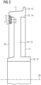
- Fig. 3 is a second partial view of a side elevation of that exemplary second embodiment variant of a sound attenuation device according to the invention, which is also shown in Fig. 2 is shown, shown in section.
- the sound attenuation device has a ring package 2 and a cuboid closure piece 3.
- the sound attenuation device is connected to a wheel body 10 of a wheel of a running gear of a rail vehicle.
- the wheel includes the wheel body 10 and a tread 11.
- the wheel body 10 has a wheel hub 12, a wheel web 13 and a wheel rim 14 with a wheel flange 15.
- the first ring 4 is, as well as in connection with Fig. 1 and Fig. 2 described, inserted into a groove 9, which is provided in the wheel rim 14, opposite the tread 11.
- the ring package 2 has an opening 20, which is in connection with an exemplary first embodiment variant of a sound attenuation device according to the invention Fig. 1 is visible.
- This opening 20 is partially filled by means of the closure piece 3.
- the closure piece 3 is in that one Fig. 3
- the assembly state shown is arranged between the wheel web 13 and the first ring 4, the first ring 4 holding the closure piece 3 in the area of a sound damping device according to the invention in connection with the exemplary first embodiment variant Fig. 1 visible first end 18 of the ring package 2 overlaps.
- the closure piece 3 is made of steel, although other materials are also conceivable, such as stainless steel, copper, etc.
- the closure piece 3 has a dowel pin 21.
- a total thickness of the closure piece 3 with the dowel pin 21 is approximately 20 mm.
- a distance between the wheel web 13 and the first ring 4 is approximately 30 mm.
- the dowel pin 21 is inserted with a press fit into a first bore 22 of the first ring 4, which is provided in the area of the first end 18 of the ring package 2.
- closure piece 3 and the first ring 4 are screwed together in the area of the first end 18 of the ring package 2 by means of a first hexagon screw 24 and a first nut 27 as well as a second hexagon screw 25 and a second nut 28.
- the closure piece 3 is thus positively and non-positively connected to the ring package 2.
- the first hexagon screw 24 and the second hexagon screw 25 are designed as through screws.
- an arrangement of blind hole screws between the ring package 2 and the closure piece 3 is also conceivable, whereby the first nut 27 and the second nut 28 can be dispensed with.
- the closure piece 3 is designed and arranged in such a way that a total unbalance of the wheel with the sound attenuation device according to the invention is smaller than a total unbalance limit value of the wheel.
Landscapes
- Engineering & Computer Science (AREA)
- Mechanical Engineering (AREA)
- Braking Arrangements (AREA)
- Tires In General (AREA)
- Body Structure For Vehicles (AREA)
- Vehicle Body Suspensions (AREA)
Description
- Die Erfindung betrifft eine Schalldämpfungsvorrichtung für Fahrzeugräder, insbesondere für Räder von Schienenfahrzeugen, umfassend ein Ringpaket mit zumindest einem offenen ersten Ring und einem offenen zweiten Ring, welchen eine viskoelastische erste Schicht oder ein offener Elastikring zwischengeordnet ist, wobei zumindest der erste Ring in einer Vertiefung eines Radkörpers eines Rads mit dem Radkörper verspannbar ist.
- Bei einer Auslegung von Rädern von Fahrzeugen, beispielsweise von Schienenfahrzeugen, müssen durch Behörden oder Kunden festgelegte Geräuschgrenzwerte (z.B. betreffend Vorbeifahrtgeräusche der Fahrzeuge) berücksichtigt werden. Insbesondere bei hohen Fahrgeschwindigkeiten treten häufig starke Schallemissionen auf, welche oft durch Schallabsorber gedämpft werden. Weiterhin ist eine effektive Schalldämpfung in stark bebauten Umgebungen (z.B. für Fahrzeuge des Stadtverkehrs, wie beispielsweise Straßenbahnen) wichtig. Aus dem Stand der Technik ist beispielsweise die
WO 2014/131676 A1 bekannt, in welcher ein schallgedämpftes Rad eines Schienenfahrzeugs beschrieben ist. An einem Radkranz, einer Radmitte zugewandt, sind paketartige Dämpfungselemente mit einer Mehrzahl an Schwingmassen unterschiedlicher Dicken vorgesehen. Diese Dämpfungselemente sind über viskoelastische Schichten mit dem Rad verbunden. Den Schwingmassen sind ferner viskoelastische Schichten unterschiedlicher Dicken zwischengeordnet. - Weiterhin zeigt die
EP 0 466 540 A1 (und das FamilienmitgliedDE 691 05 379 T2 ) einen ringförmigen Schwingungsdämpfer, bei welchem offenen Ringen eine oder mehrere viskoelastische Schichten zwischengeordnet sind und welcher an einer Stirnseite eines Getrieberads in einer Vertiefung des Getrieberads vorgesehen ist. - Es ist in der
EP 0 466 540 A1 jedoch nicht ersichtlich, inwieweit der Schwingungsdämpfer mittels eines Verschlusses gesichert ist. - Der Erfindung liegt die Aufgabe zugrunde, eine gegenüber dem Stand der Technik weiterentwickelte, konstruktiv einfache, auch für hohe Fahrgeschwindigkeiten und klotzgebremste Räder geeignete Schalldämpfungsvorrichtung mit einer mechanischen Sicherung anzugeben.
- Erfindungsgemäß wird diese Aufgabe gelöst mit einer Schalldämpfungsvorrichtung der eingangs genannten Art, bei der ein Verschlussstück mit dem Ringpaket verbunden ist, wobei das Verschlussstück in einer Öffnung zwischen einem ersten Ende des Ringpakets und einem zweiten Ende des Ringpakets angeordnet ist.
- Dadurch ist das Ringpaket vor einem Herabfallen von dessen Träger (z.B. von dem Rad) geschützt. Es wird dadurch eine redundante Verlustsicherung erzielt, da der erste Ring zusätzlich auch in der Vertiefung des Rads vorgespannt bzw. mit dem Rad verspannt ist. Relativbewegungen des ersten Endes und des zweiten Endes des Ringpakets zueinander und gegeneinander werden aufgrund des Verschlussstücks auf ein vernachlässigbares bzw. notwendiges Ausmaß eingegrenzt.
- Ein unbeabsichtigtes Ausfädeln des Ringpakets aus der Vertiefung wird dadurch vermieden.
- Daher kann die erfindungsgemäße Schalldämpfungsvorrichtung auch bei Fahrzeugen mit hohen Fahrgeschwindigkeiten (z.B. bei Schienenfahrzeugen im Hochgeschwindigkeitsbetrieb, welche mit Fahrgeschwindigkeiten von größer als 300 km/h verkehren) sowie in Umgebungen mit starken Vibrationen, Stößen etc. eingesetzt werden. Selbstverständlich ist ein Einsatz der erfindungsgemäßen Schalldämpfungsvorrichtung auch für Fahrzeuge im Stadtverkehr (z.B. für Straßenbahnen) möglich. Die Verlustsicherung weist eine geringe konstruktive Komplexität auf, auch eine Montage und eine Demontage des Verschlussstücks und des Ringpakets sind einfach und wenig zeitaufwendig.
- Günstig ist es, wenn zwischen dem Verschlussstück und dem Ringpaket im Bereich des ersten Endes oder des zweiten Endes ein Spalt ausgebildet ist.
- Dadurch werden ein Toleranzausgleich und eine vereinfachte Montage des Verschlussstücks bewirkt.
- Eine besonders einfache und robuste Ausgestaltung erhält man, wenn das Ringpaket zumindest im Bereich des ersten Endes zumindest eine erste Bohrung aufweist, in welche ein Passstift des Verschlussstücks oder ein mit dem Verschlussstück verbundenes Passungsteil eingeführt ist.
- In diesem Zusammenhang ist es auch hilfreich, wenn das Ringpaket im Bereich des zweiten Endes zumindest eine zweite Bohrung aufweist.
- Dadurch wird eine Flexibilität in Bezug auf eine Orientierung des Verschlussstücks in der erfindungsgemäßen Schalldämpfungsvorrichtung erreicht. Der Passstift oder das Passungsteil kann in die erste Bohrung im Bereich des ersten Endes des Ringpakets, alternativ aber auch in die zweite Bohrung im Bereich des zweiten Endes des Ringpakets eingeführt werden.
- Eine alternative Lösung zur Verbindung des Verschlussstücks mit dem Ringpaket wird erzielt, wenn zumindest im Bereich des ersten Endes das Ringpaket zumindest einen Passstift aufweist oder mit dem Ringpaket zumindest ein Passungsteil verbunden ist, welcher oder welches in eine Bohrung des Verschlussstücks eingeführt ist.
- Günstig ist es außerdem, wenn das Ringpaket mit dem Verschlussstück verschraubt ist.
- Durch diese Maßnahme wird eine besonders sichere Verbindung des Verschlussstücks mit dem Ringpaket bewirkt. Ist das Verschlussstück über den Passstift oder das Passungsteil mit dem Ringpaket gekoppelt und zusätzlich mit dem Ringpaket verschraubt, so wird eine redundante Verbindung des Verschlussstücks mit dem Ringpaket erreicht.
- Eine vorteilhafte Lösung wird erzielt, wenn das Ringpaket das Verschlussstück überlappend ausgebildet und angeordnet ist. In diesem Zusammenhang ist es hilfreich, wenn der zumindest erste Ring zusammen mit dem Verschlussstück im Bereich der Öffnung einen Rücksprung bildend angeordnet ist.
- Durch diese Maßnahmen wird auf dem Ringpaket ein Montagebereich (z.B. mit der ersten Bohrung oder dem Passstift bzw. dem Passungsteil) zur Verbindung des Verschlussstücks mit dem Ringpaket bereitgehalten.
- Für einen Einführungsvorgang des Ringpakets in dessen Träger ist es vorteilhaft, wenn der zumindest erste Ring einen größeren Außendurchmesser als der zweite Ring aufweist.
- Eine besondere sichere Verbindung des Ringpakets mit dessen Träger erzielt man, wenn der zumindest erste Ring in einer Nut des Radkörpers, welche auf einer Seite eines Radkranzes des Rads, welche einer Lauffläche des Rads abgewandt ist, vorgesehen ist, mit dem Radkörper verspannbar ist.
- Durch diese Maßnahme wird außerdem eine besonders effektive Schalldämpfung erreicht, da das Ringpaket nahe an der Lauffläche des Rads, d.h. in einem Bereich mit starker Schallemission, angeordnet ist.
- Hilfreich ist es weiterhin, wenn das Verschlussstück in einer Weise ausgeführt und angeordnet ist, dass eine Gesamtunwucht des Rads mit der Schalldämpfungsvorrichtung gleich oder kleiner als ein Gesamtunwucht-Grenzwert des Rads ist.
- Durch diese Maßnahme wird vermieden, dass das Rad aufgrund der erfindungsgemäßen Schalldämpfungsvorrichtung eine unzulässig große Gesamtunwucht aufweist.
- Zur Montage der erfindungsgemäßen Schalldämpfungsvorrichtung auf einem Rad ist es günstig, wenn in einem ersten Montageschritt das Ringpaket unter Vorspannung in die Vertiefung des Radkörpers eingeführt wird, in einem zweiten Montageschritt das Verschlussstück in die Öffnung eingeführt wird und in einem dritten Montageschritt das Verschlussstück mit dem Ringpaket verbunden wird.
- Dadurch wird eine schnelle und sichere Verbindung der erfindungsgemäßen Schalldämpfungsvorrichtung mit dem Rad bewirkt.
- Nachfolgend wird die Erfindung anhand von Ausführungsbeispielen näher erläutert.
- Es zeigen beispielhaft:
- Fig. 1:
- Einen Grundriss einer beispielhaften ersten Ausführungsvariante einer erfindungsgemäßen, mit einem Rad verbundenen Schalldämpfungsvorrichtung mit einem Ringpaket und einem Verschlussstück,
- Fig. 2:
- Eine erste Teilansicht eines Seitenrisses einer beispielhaften zweiten Ausführungsvariante einer erfindungsgemäßen Schalldämpfungsvorrichtung in geschnittener Darstellung, wobei ein Ringpaket mit einem Rad verbunden ist, und
- Fig. 3:
- Eine zweite Teilansicht des Seitenrisses der beispielhaften zweiten Ausführungsvariante einer erfindungsgemäßen Schalldämpfungsvorrichtung in geschnittener Darstellung, wobei ein Verschlussstück sichtbar ist.
-
Fig. 1 zeigt einen Grundriss einer beispielhaften ersten Ausführungsvariante einer erfindungsgemäßen Schalldämpfungsvorrichtung, welche mit einem Rad eines Fahrwerks eines Schienenfahrzeugs, welches eine Klotzbremse 1 aufweist, verbunden ist. - Erfindungsgemäß ist es jedoch auch denkbar, dass das Fahrwerk keine oder eine andere Bremse aufweist. Weist das Fahrwerk beispielsweise eine Radscheibenbremse auf, so kann die erfindungsgemäße Schalldämpfungsvorrichtung innerhalb oder außerhalb eines Reibrings der Radscheibenbremse auf dem Rad angeordnet sein.
- Die Schalldämpfungsvorrichtung umfasst ein Ringpaket 2 und ein Verschlussstück 3. Das Ringpaket 2 weist einen offenen ersten Ring 4, einen offenen zweiten Ring 5 und einen offenen dritten Ring 6 auf, welche über eine viskoelastische erste Schicht 7 sowie eine viskoelastische zweite Schicht 8 über Vulkanisierung miteinander verbunden sind.
- Der zweite Ring 5, der dritte Ring 6 sowie die erste Schicht 7 und die zweite Schicht 8 sind in
Fig. 1 nicht sichtbar. - Der erste Ring 4 ist in eine als Nut 9 ausgebildete, in
Fig. 1 nicht sichtbare Vertiefung eines Radkörpers 10 des Rads unter Eigenspannung eingeführt und in der Nut 9 mit dem Radkörper 10 verspannt. - Das Rad umfasst den Radkörper 10 sowie eine Lauffläche 11, welche eine Schiene eines in
Fig. 1 nicht gezeigten Gleises kontaktiert. Der Radkörper 10 weist eine Radnabe 12, einen Radsteg 13 sowie einen Radkranz 14 mit einem Spurkranz 15 auf. - Die Nut 9 ist umlaufend in dem Radkranz 14 auf einer der Lauffläche 11 abgewandten bzw. gegenüberliegenden Seite ausgebildet, wodurch sich das Ringpaket 2 in Richtung der Radnabe 12 bzw. in Richtung einer Radmitte erstreckt.
- Der erste Ring 4 ist einer Radaußenseite 16, der dritte Ring 6 einer im Zusammenhang mit einer beispielhaften zweiten Ausführungsvariante einer erfindungsgemäßen Schalldämpfungsvorrichtung in
Fig. 2 undFig. 3 sichtbaren Radinnenseite 17 und dem Radsteg 13 zugewandt angeordnet. Der zweite Ring 5 ist dem ersten Ring 4 und dem dritten Ring 6 zwischengeordnet. - Zwischen dem dritten Ring 6 und dem Radsteg 13 ist ein ausreichender Freiraum zur Verbindung des Verschlussstücks 3 mit dem Ringpaket 2 vorgesehen.
- Wie erwähnt sind der erste Ring 4, der zweite Ring 5 und der dritte Ring 6 als offene Ringe ausgeführt und ermöglichen dadurch ein Einführen des ersten Rings 4 in die Nut 9.
- Das Ringpaket 2 weist dadurch weiterhin zwischen einem ersten Ende 18 des Ringpakets 2 und einem zweiten Ende 19 des Ringpakets 2 eine Öffnung 20 auf.
- Diese Öffnung 20 ist in jenem in
Fig. 1 gezeigten Montagezustand der erfindungsgemäßen Schalldämpfungsvorrichtung mittels des Verschlussstücks 3 teilweise ausgefüllt. - Das Verschlussstück 3 ist in diesem Montagezustand zwischen dem Radsteg 13 und dem ersten Ring 4 angeordnet, wobei der erste Ring 4 das Verschlussstück 3 im Bereich des ersten Endes 18 überlappt. Dadurch ist die Öffnung 20 im Bereich des ersten Rings 4 nicht durch das Verschlussstück 3 ausgefüllt. Vielmehr bildet der erste Ring 4 zusammen mit dem Verschlussstück 3 im Bereich der Öffnung 20 einen Rücksprung.
- Das Verschlussstück 3 ist in Stahl ausgebildet und weist einen zylindrischen Passstift 21 auf, welcher einstückig mit dem Verschlussstück 3 ausgebildet ist. In jenem in
Fig. 1 gezeigten Montagezustand ist der Passstift 21 mit einer Presspassung in eine erste Bohrung 22 des ersten Rings 4, welche im Bereich des ersten Endes 18 des Ringpakets 2 vorgesehen ist, eingeführt. - Zusätzlich sind das Verschlussstück 3 und der erste Ring 4 mittels einer ersten Sechskantschraube 24 und einer zweiten Sechskantschraube 25 miteinander verschraubt.
- Im Bereich des zweiten Endes 19 ist zwischen dem Verschlussstück 3 und dem Ringpaket 2 ein schmaler Spalt entlang von Kanten des Verschlussstücks 3 und des Ringpakets 2 ausgebildet, welcher in Richtung einer beispielhaft in
Fig. 2 gezeigten Radachse 26 verläuft. - Im Bereich des zweiten Endes 19 des Ringpakets 2 weist der erste Ring 4 eine zweite Bohrung 23 auf, wodurch das Verschlussstück 3 bei geeigneter geometrischer Ausbildung auch in einer in Bezug auf den in
Fig. 1 gezeigten Montagezustand um 180° gedrehten Orientierung mit dem Ringpaket 2 verbunden werden kann, wobei der Passstift 21 in die zweite Bohrung 23 einzuführen ist. Soll das Verschlussstück 3 in dieser um 180° gedrehten Orientierung mit dem Ringpaket 2 verschraubt werden, so müssen im Bereich des zweiten Endes 19 des Ringpakets 2 zusätzliche Bohrungen für Schrauben gefertigt werden. - Erfindungsgemäß ist es jedoch auch denkbar, auf die zweite Bohrung 23 zu verzichten und den ersten Ring 4 im Bereich des zweiten Endes 19 des Ringpakets 2 bündig mit dem zweiten Ring 5 und dem dritten Ring 6 auszubilden.
- Erfindungsgemäß ist es ferner auch vorstellbar, dass nicht das Verschlussstück 3 den Passstift 21 aufweist, sondern beispielsweise der erste Ring 4, und dass nicht der erste Ring 4 die erste Bohrung 22 aufweist, sondern das Verschlussstück 3.
- Darüber hinaus ist es beispielsweise auch denkbar, dass mehr als ein Passstift 21 des Verschlussstücks 3 oder des ersten Rings 4 in eine entsprechende Anzahl an Bohrungen des ersten Rings 4 oder des Verschlussstücks 3 eingeführt sind.
- Ferner ist es möglich, den Passstift 21 oder ein anderes Passungsteil (z.B. ein quaderförmiges Passungsteil) separat auszubilden und mit dem Verschlussstück 3 oder mit dem Ringpaket 2 zu verbinden (z.B. zu verschweißen, zu verspannen etc.).
- Das Verschlussstück 3 ist quaderförmig ausgebildet. Erfindungsgemäß ist es jedoch auch denkbar, dass das Verschlussstück 3 eine kreisringsektorförmige oder eine trapezförmige Grund- und Deckfläche aufweist.
- Bei einer kreisringsektorförmigen oder trapezförmigen Ausbildung der Grund- und Deckfläche ist jedoch ein Verlust an Flexibilität bei der Orientierung des Verschlussstücks 3 in der Öffnung 20 und bei dessen Verbindung mit dem Ringpaket 2 zu berücksichtigen.
- Aufgrund seiner Anordnung in der Öffnung 20, seiner Form, seiner der Öffnung 20 angepassten Dimensionen sowie seiner Masse trägt das Verschlussstück 3 im Ausmaß von 12 m·g zu einer Gesamtunwucht des Rads und der Schalldämpfungsvorrichtung von 27 m·g bei. Diese Gesamtunwucht ist somit kleiner als ein Gesamtunwucht-Grenzwert des Rads von 30 m·g.
- Zur Montage der erfindungsgemäßen Schalldämpfungsvorrichtung wird in einem ersten Montageschritt der erste Ring 4 unter Vorspannung in die Nut 9 des Radkörpers 10 eingeführt, wird in einem zweiten Montageschritt das Verschlussstück 3 in die Öffnung 20 und in den Freiraum zwischen dem Radkörper 10 und dem Ringpaket 2 eingeführt und wird in einem dritten Montageschritt das Verschlussstück 3 mittels Einführens des Passstifts 21 in die erste Bohrung 22 und mittels Verschraubens formschlüssig und kraftschlüssig mit dem Ringpaket 2 verbunden.
- Erfindungsgemäß ist es auch denkbar, vor Einführung des ersten Rings 4 in die Nut 9 eine handelsübliche Montagepaste in die Nut 9 einzubringen.
- Weiterhin ist es vorstellbar, das Verschlussstück 3 mit dem Ringpaket 2 zu verkleben.
- In
Fig. 2 ist eine erste Teilansicht eines Seitenrisses einer beispielhaften zweiten Ausführungsvariante einer erfindungsgemäßen Schalldämpfungsvorrichtung geschnitten dargestellt, bei welcher ein Ringpaket 2 mit einem Rad eines Fahrwerks eines Schienenfahrzeugs verbunden ist. - Das Ringpaket 2 weist einen offenen ersten Ring 4, einen offenen zweiten Ring 5 und einen offenen dritten Ring 6 auf, welche über eine viskoelastische erste Schicht 7 sowie eine viskoelastische zweite Schicht 8 über Vulkanisierung miteinander verbunden sind.
- Die erste Schicht 7 ist dabei dem ersten Ring 4 und dem zweiten Ring 5 zwischengeordnet, die zweite Schicht 8 dem zweiten Ring 5 und dem dritten Ring 6.
- Erfindungsgemäß ist es jedoch auch vorstellbar, anstatt der ersten Schicht 7 und der zweiten Schicht 8 zwischen dem ersten Ring 4 und dem zweiten Ring 5 einen offenen ersten Elastikring sowie zwischen dem zweiten Ring 5 und dem dritten Ring 6 einen offenen zweiten Elastikring vorzusehen und den ersten Elastikring und den zweiten Elastikring mit dem Ringpaket 2 zu verbinden (z.B. zu verkleben).
- Die erste Schicht 7 und die zweite Schicht 8 sind in einem Elastomerwerkstoff ausgeführt und weisen jeweils eine Dicke von ca. 2 mm auf.
- Der erste Ring 4, der zweite Ring 5 und der dritte Ring 6 weisen jeweils eine Dicke von ca. 5 mm auf und sind in Stahl ausgebildet. Erfindungsgemäß ist jedoch auch ein Einsatz anderer Werkstoffe für den ersten Ring 4, den zweiten Ring 5 und den dritten Ring 6 möglich, wie beispielsweise Edelstahl, Kupfer etc.
- Der erste Ring 4 weist einen größeren Außendurchmesser als der zweite Ring 5 und der dritte Ring 6 auf. Ein entsprechender Überstand des ersten Rings 4 ist unter Vorspannung des ersten Rings 4 in eine als Nut 9 ausgebildete Vertiefung eines Radkörpers 10 des Rads eingeführt und in der Nut 9 mit dem Radkörper 10 verspannt.
- Das Rad umfasst den Radkörper 10 sowie eine Lauffläche 11, welche eine Schiene eines in
Fig. 2 nicht gezeigten Gleises kontaktiert. Der Radkörper 10 weist eine Radnabe 12, einen Radsteg 13 sowie einen Radkranz 14 mit einem Spurkranz 15 auf. - Die Nut 9 ist umlaufend in dem Radkranz 14 auf einer der Lauffläche 11 abgewandten Seite ausgebildet, wodurch sich das Ringpaket 2 in Richtung der Radnabe 12 bzw. in Richtung einer Radmitte (Radachse 26) erstreckt.
- Der erste Ring 4 ist einer Radaußenseite 16, der dritte Ring 6 einer Radinnenseite 17 und dem Radsteg 13 zugewandt angeordnet. Der zweite Ring 5 ist dem ersten Ring 4 und dem dritten Ring 6 zwischengeordnet.
- Zwischen dem dritten Ring 6 und dem Radsteg 13 ist ein ausreichender Freiraum zur Verbindung eines in
Fig. 3 sichtbaren Verschlussstücks 3 mit dem Ringpaket 2 vorgesehen. - Die Schalldämpfungsvorrichtung ist an der Radaußenseite 16 vorgesehen. Erfindungsgemäß ist es jedoch auch vorstellbar, die Schalldämpfungsvorrichtung an der Radinnenseite 17 mit dem Rad zu verbinden.
- Weiterhin ist es denkbar, eine erste Schalldämpfungsvorrichtung an der Radaußenseite 16 und eine zweite Schalldämpfungsvorrichtung an der Radinnenseite 17 anzuordnen, wobei die zweite Schalldämpfungsvorrichtung auf einer ersten Nut (der Nut 9) in Bezug auf den Radsteg 13 gegenüberliegenden Seite in einer zweiten Nut mit dem Radkörper 10 verspannt werden kann.
- In
Fig. 3 ist eine zweite Teilansicht eines Seitenrisses jener beispielhaften zweiten Ausführungsvariante einer erfindungsgemäßen Schalldämpfungsvorrichtung, die auch inFig. 2 gezeigt ist, geschnitten dargestellt. - Die Schalldämpfungsvorrichtung weist ein Ringpaket 2 und ein quaderförmiges Verschlussstück 3 auf.
- Von dem Ringpaket 2, welches, wie in
Fig. 2 gezeigt, einen offenen ersten Ring 4, einen offenen zweiten Ring 5 und einen offenen dritten Ring 6 sowie eine viskoelastische erste Schicht 7 und eine viskoelastische zweite Schicht 8 aufweist, ist inFig. 3 nur der erste Ring 4 sichtbar. - Die Schalldämpfungsvorrichtung ist mit einem Radkörper 10 eines Rads eines Fahrwerks eines Schienenfahrzeugs verbunden. Das Rad umfasst den Radkörper 10 sowie eine Lauffläche 11. Der Radkörper 10 weist eine Radnabe 12, einen Radsteg 13 sowie einen Radkranz 14 mit einem Spurkranz 15 auf.
- Der erste Ring 4 ist, wie auch im Zusammenhang mit
Fig. 1 undFig. 2 beschrieben, in eine Nut 9 eingeführt, welche in dem Radkranz 14, der Lauffläche 11 gegenüberliegend, vorgesehen ist. - Das Ringpaket 2 weist eine Öffnung 20 auf, die im Zusammenhang mit einer beispielhaften ersten Ausführungsvariante einer erfindungsgemäßen Schalldämpfungsvorrichtung in
Fig. 1 sichtbar ist. - Diese Öffnung 20 ist mittels des Verschlussstücks 3 teilweise ausgefüllt. Das Verschlussstück 3 ist in jenem in
Fig. 3 gezeigten Montagezustand zwischen dem Radsteg 13 und dem ersten Ring 4 angeordnet, wobei der erste Ring 4 das Verschlussstück 3 im Bereich eines im Zusammenhang mit der beispielhaften ersten Ausführungsvariante einer erfindungsgemäßen Schalldämpfungsvorrichtung inFig. 1 sichtbaren ersten Endes 18 des Ringpakets 2 überlappt. - Das Verschlussstück 3 ist in Stahl ausgebildet, wobei jedoch auch andere Werkstoffe denkbar sind, wie beispielsweise Edelstahl, Kupfer etc.
- Das Verschlussstück 3 weist einen Passstift 21 auf. Eine Gesamtdicke des Verschlussstücks 3 mit dem Passstift 21 beträgt ca. 20 mm.
- Um das Verschlussstück 3 in einen Bereich zwischen dem Radsteg 13 und dem ersten Ring 4 einführen zu können, beträgt eine Distanz zwischen dem Radsteg 13 und dem ersten Ring 4 ca. 30 mm.
- In dem in
Fig. 3 gezeigten Montagezustand ist der Passstift 21 mit einer Presspassung in eine erste Bohrung 22 des ersten Rings 4, welche im Bereich des ersten Endes 18 des Ringpakets 2 vorgesehen ist, eingeführt. - Zusätzlich sind das Verschlussstück 3 und der erste Ring 4 im Bereich des ersten Endes 18 des Ringpaktes 2 mittels einer ersten Sechskantschraube 24 und einer ersten Mutter 27 sowie einer zweiten Sechskantschraube 25 und einer zweiten Mutter 28 miteinander verschraubt.
- Das Verschlussstück 3 ist somit formschlüssig und kraftschlüssig mit dem Ringpaket 2 verbunden.
- Die erste Sechskantschraube 24 und die zweite Sechskantschraube 25 sind als Durchgangsschrauben ausgebildet. Erfindungsgemäß ist jedoch auch eine Anordnung von Sacklochschrauben zwischen dem Ringpaket 2 und dem Verschlussstück 3 denkbar, wodurch auf die erste Mutter 27 und die zweite Mutter 28 verzichtet werden kann.
- Wie auch im Zusammenhang mit
Fig. 1 beschrieben, ist das Verschlussstück 3 in einer Weise ausgeführt und angeordnet, dass eine Gesamtunwucht des Rads mit der erfindungsgemäßen Schalldämpfungsvorrichtung kleiner als ein Gesamtunwucht-Grenzwert des Rads ist. -
- 1
- Klotzbremse
- 2
- Ringpaket
- 3
- Verschlussstück
- 4
- Erster Ring
- 5
- Zweiter Ring
- 6
- Dritter Ring
- 7
- Erste Schicht
- 8
- Zweite Schicht
- 9
- Nut
- 10
- Radkörper
- 11
- Lauffläche
- 12
- Radnabe
- 13
- Radsteg
- 14
- Radkranz
- 15
- Spurkranz
- 16
- Radaußenseite
- 17
- Radinnenseite
- 18
- Erstes Ende
- 19
- Zweites Ende
- 20
- Öffnung
- 21
- Passstift
- 22
- Erste Bohrung
- 23
- Zweite Bohrung
- 24
- Erste Sechskantschraube
- 25
- Zweite Sechskantschraube
- 26
- Radachse
- 27
- Erste Mutter
- 28
- Zweite Mutter
Claims (19)
- Schalldämpfungsvorrichtung für Fahrzeugräder, insbesondere für Räder von Schienenfahrzeugen, umfassend ein Ringpaket (2) mit zumindest einem offenen ersten Ring (4) und einem offenen zweiten Ring (5), welchen eine viskoelastische erste Schicht (7) oder ein offener Elastikring zwischengeordnet ist, wobei zumindest der erste Ring (4) in einer Vertiefung eines Radkörpers (10) eines Rads mit dem Radkörper (10) verspannbar ist, dadurch gekennzeichnet, dass ein Verschlussstück (3) mit dem Ringpaket (2) verbunden ist, wobei das Verschlussstück (3) in einer Öffnung (20) zwischen einem ersten Ende (18) des Ringpakets (2) und einem zweiten Ende (19) des Ringpakets (2) angeordnet ist.
- Schalldämpfungsvorrichtung nach Anspruch 1, dadurch gekennzeichnet, dass zwischen dem Verschlussstück (3) und dem Ringpaket (2) im Bereich des ersten Endes (18) oder des zweiten Endes (19) ein Spalt ausgebildet ist.
- Schalldämpfungsvorrichtung nach Anspruch 1 oder 2, dadurch gekennzeichnet, dass das Verschlussstück (3) zwischen einem Radsteg (13) und dem zumindest ersten Ring (4) anordenbar ist.
- Schalldämpfungsvorrichtung nach einem der Ansprüche 1 bis 3, dadurch gekennzeichnet, dass das Verschlussstück (3) formschlüssig mit dem Ringpaket (2) verbunden ist.
- Schalldämpfungsvorrichtung nach einem der Ansprüche 1 bis 4, dadurch gekennzeichnet, dass das das Verschlussstück (3) kraftschlüssig mit dem Ringpaket (2) verbunden ist.
- Schalldämpfungsvorrichtung nach einem der Ansprüche 1 bis 5, dadurch gekennzeichnet, dass das Verschlussstück (3) mit dem Ringpaket (2) verklebt ist.
- Schalldämpfungsvorrichtung nach einem der Ansprüche 4 bis 6, dadurch gekennzeichnet, dass das Ringpaket (2) zumindest im Bereich des ersten Endes (18) zumindest eine erste Bohrung (22) aufweist, in welche ein Passstift (21) des Verschlussstücks (3) oder ein mit dem Verschlussstück (3) verbundenes Passungsteil eingeführt ist.
- Schalldämpfungsvorrichtung nach Anspruch 7, dadurch gekennzeichnet, dass das Ringpakets (2) im Bereich des zweiten Endes (19) zumindest eine zweite Bohrung (23) aufweist.
- Schalldämpfungsvorrichtung nach einem der Ansprüche 4 bis 6, dadurch gekennzeichnet, dass zumindest im Bereich des ersten Endes (18) das Ringpaket (2) zumindest einen Passstift (21) aufweist oder mit dem Ringpaket (2) zumindest ein Passungsteil verbunden ist, welcher oder welches in eine Bohrung des Verschlussstücks (3) eingeführt ist.
- Schalldämpfungsvorrichtung nach einem der Ansprüche 5 bis 9, dadurch gekennzeichnet, dass das Ringpaket (2) mit dem Verschlussstück (3) verschraubt ist.
- Schalldämpfungsvorrichtung nach einem der Ansprüche 1 bis 10, dadurch gekennzeichnet, dass das Ringpaket (2) das Verschlussstück (3) überlappend ausgebildet und angeordnet ist.
- Schalldämpfungsvorrichtung nach Anspruch 11, dadurch gekennzeichnet, dass der zumindest erste Ring (4) zusammen mit dem Verschlussstück (3) im Bereich der Öffnung (20) einen Rücksprung bildend angeordnet ist.
- Schalldämpfungsvorrichtung nach einem der Ansprüche 1 bis 12, dadurch gekennzeichnet, dass der zumindest erste Ring (4) einen größeren Außendurchmesser als der zweite Ring (5) aufweist.
- Schalldämpfungsvorrichtung nach einem der Ansprüche 1 bis 13, dadurch gekennzeichnet, dass der zumindest erste Ring (4) in einer Nut (9) des Radkörpers (10), welche auf einer Seite eines Radkranzes (14) des Rads, welche einer Lauffläche (11) des Rads abgewandt ist, vorgesehen ist, mit dem Radkörper (10) verspannbar ist.
- Schalldämpfungsvorrichtung nach einem der Ansprüche 1 bis 14, dadurch gekennzeichnet, dass das Verschlussstück (3) in einer Weise ausgeführt und angeordnet ist, dass eine Gesamtunwucht des Rads mit der Schalldämpfungsvorrichtung gleich oder kleiner als ein Gesamtunwucht-Grenzwert des Rads ist.
- Rad für Schienenfahrzeuge mit zumindest einer Schalldämpfungsvorrichtung nach einem der Ansprüche 1 bis 15.
- Rad nach Anspruch 16, dadurch gekennzeichnet, dass eine erste Schalldämpfungsvorrichtung an einer Radaußenseite (16) vorgesehen ist und eine zweite Schalldämpfungsvorrichtung an einer Radinnenseite (17) vorgesehen ist.
- Fahrwerk für Schienenfahrzeuge mit Rädern nach Anspruch 16 oder 17, dadurch gekennzeichnet, dass zumindest eine Klotzbremse (1) vorgesehen ist.
- Verfahren zur Montage einer Schalldämpfungsvorrichtung nach einem der Ansprüche 1 bis 15 auf einem Rad nach Anspruch 16 oder 17, dadurch gekennzeichnet, dass in einem ersten Montageschritt das Ringpaket (2) unter Vorspannung in die Vertiefung des Radkörpers (10) eingeführt wird, in einem zweiten Montageschritt das Verschlussstück (3) in die Öffnung (20) eingeführt wird und in einem dritten Montageschritt das Verschlussstück (3) mit dem Ringpaket (2) verbunden wird.
Applications Claiming Priority (2)
| Application Number | Priority Date | Filing Date | Title |
|---|---|---|---|
| ATA50279/2020A AT523426B1 (de) | 2020-04-02 | 2020-04-02 | Schalldämpfungsvorrichtung für Fahrzeugräder |
| PCT/EP2021/057899 WO2021198062A1 (de) | 2020-04-02 | 2021-03-26 | Schalldämpfungsvorrichtung für fahrzeugräder |
Publications (2)
| Publication Number | Publication Date |
|---|---|
| EP4103409A1 EP4103409A1 (de) | 2022-12-21 |
| EP4103409B1 true EP4103409B1 (de) | 2023-11-15 |
Family
ID=75478004
Family Applications (1)
| Application Number | Title | Priority Date | Filing Date |
|---|---|---|---|
| EP21718033.0A Active EP4103409B1 (de) | 2020-04-02 | 2021-03-26 | Schalldämpfungsvorrichtung für fahrzeugräder |
Country Status (5)
| Country | Link |
|---|---|
| US (1) | US20230150301A1 (de) |
| EP (1) | EP4103409B1 (de) |
| CN (1) | CN220281034U (de) |
| AT (1) | AT523426B1 (de) |
| WO (1) | WO2021198062A1 (de) |
Families Citing this family (1)
| Publication number | Priority date | Publication date | Assignee | Title |
|---|---|---|---|---|
| AT525807B1 (de) | 2022-08-22 | 2023-08-15 | Siemens Mobility Austria Gmbh | Schalldämpfungsvorrichtung für Fahrzeugräder |
Citations (12)
| Publication number | Priority date | Publication date | Assignee | Title |
|---|---|---|---|---|
| DE3316759C1 (de) | 1983-05-07 | 1984-10-25 | Klöckner-Werke AG, 4100 Duisburg | Geräuschgedämpftes Schienenrad |
| EP0466540B1 (de) | 1990-07-12 | 1994-11-30 | Sa Enac | Schwingungsdämpfungseinrichtung |
| CN1123378A (zh) | 1994-11-17 | 1996-05-29 | 日野自动车工业株式会社 | 齿轮、皮带轮等回转体 |
| JP3991317B2 (ja) | 2003-07-04 | 2007-10-17 | 住友金属工業株式会社 | 防音車輪及びこれに用いる防音リング |
| CN201494248U (zh) | 2009-10-15 | 2010-06-02 | 哈尔滨汇凯科技开发有限公司 | 管式降噪阻尼器 |
| EP2118516B1 (de) | 2007-02-11 | 2011-12-28 | Le Confort Acoustique SARL | Schwingungsdämpfungsvorrichtung |
| EP2230096B1 (de) * | 2009-03-16 | 2013-04-17 | Siemens AG Österreich | Schienenfahrzeug mit Radschallabsorber |
| CN104723790A (zh) | 2015-01-23 | 2015-06-24 | 马钢(集团)控股有限公司 | 一种车轮阻尼环连接装置及连接方法 |
| CN106004228A (zh) | 2016-07-19 | 2016-10-12 | 哈尔滨通达工业环保自动化有限公司 | 车轮用合成阻尼环 |
| CN205970619U (zh) | 2016-07-27 | 2017-02-22 | 马鞍山市金轮环件轧钢有限责任公司 | 一种车轮消音环 |
| EP2979896B1 (de) * | 2013-03-28 | 2018-03-14 | Nippon Steel & Sumitomo Metal Corporation | Schallgedämpftes rad für ein schienenfahrzeug |
| CN209096377U (zh) | 2018-10-23 | 2019-07-12 | 青岛陆海利达交通装备有限公司 | 轨道车辆车轮降噪阻尼装置 |
Family Cites Families (5)
| Publication number | Priority date | Publication date | Assignee | Title |
|---|---|---|---|---|
| EP2554399B1 (de) * | 2011-08-03 | 2014-07-23 | Valdunes | Vorrichtung zur Dämpfung des Knirschgeräusches eines Metallrads auf einer metallischen Rolloberfläche |
| WO2014131676A1 (de) | 2013-02-28 | 2014-09-04 | Siemens Ag Österreich | Schallgedämpftes rad für schienenfahrzeuge |
| FR3071193B1 (fr) * | 2017-09-20 | 2019-10-18 | Alstom Transport Technologies | Dispositif absorbeur de bruit pour roue de vehicule ferroviaire et roue de vehicule ferroviaire associee |
| CN109249750B (zh) * | 2018-10-09 | 2021-10-01 | 株洲时代新材料科技股份有限公司 | 车轮轴向降噪方法、车轮及其设计方法 |
| CN110641226B (zh) * | 2019-10-25 | 2022-07-29 | 株洲时代新材料科技股份有限公司 | 弹性车轮降噪阻尼器及其组装安装方法 |
-
2020
- 2020-04-02 AT ATA50279/2020A patent/AT523426B1/de active
-
2021
- 2021-03-26 WO PCT/EP2021/057899 patent/WO2021198062A1/de not_active Ceased
- 2021-03-26 US US17/915,846 patent/US20230150301A1/en active Pending
- 2021-03-26 EP EP21718033.0A patent/EP4103409B1/de active Active
- 2021-03-26 CN CN202190000390.6U patent/CN220281034U/zh active Active
Patent Citations (12)
| Publication number | Priority date | Publication date | Assignee | Title |
|---|---|---|---|---|
| DE3316759C1 (de) | 1983-05-07 | 1984-10-25 | Klöckner-Werke AG, 4100 Duisburg | Geräuschgedämpftes Schienenrad |
| EP0466540B1 (de) | 1990-07-12 | 1994-11-30 | Sa Enac | Schwingungsdämpfungseinrichtung |
| CN1123378A (zh) | 1994-11-17 | 1996-05-29 | 日野自动车工业株式会社 | 齿轮、皮带轮等回转体 |
| JP3991317B2 (ja) | 2003-07-04 | 2007-10-17 | 住友金属工業株式会社 | 防音車輪及びこれに用いる防音リング |
| EP2118516B1 (de) | 2007-02-11 | 2011-12-28 | Le Confort Acoustique SARL | Schwingungsdämpfungsvorrichtung |
| EP2230096B1 (de) * | 2009-03-16 | 2013-04-17 | Siemens AG Österreich | Schienenfahrzeug mit Radschallabsorber |
| CN201494248U (zh) | 2009-10-15 | 2010-06-02 | 哈尔滨汇凯科技开发有限公司 | 管式降噪阻尼器 |
| EP2979896B1 (de) * | 2013-03-28 | 2018-03-14 | Nippon Steel & Sumitomo Metal Corporation | Schallgedämpftes rad für ein schienenfahrzeug |
| CN104723790A (zh) | 2015-01-23 | 2015-06-24 | 马钢(集团)控股有限公司 | 一种车轮阻尼环连接装置及连接方法 |
| CN106004228A (zh) | 2016-07-19 | 2016-10-12 | 哈尔滨通达工业环保自动化有限公司 | 车轮用合成阻尼环 |
| CN205970619U (zh) | 2016-07-27 | 2017-02-22 | 马鞍山市金轮环件轧钢有限责任公司 | 一种车轮消音环 |
| CN209096377U (zh) | 2018-10-23 | 2019-07-12 | 青岛陆海利达交通装备有限公司 | 轨道车辆车轮降噪阻尼装置 |
Non-Patent Citations (1)
| Title |
|---|
| ANONYM: "Verbindungstechnik", WIKIPEDIA, XP055660512, Retrieved from the Internet <URL:https://de.wikipedia.org/w/index.php?title=Verbindungstechnik&oldid=185903624> [retrieved on 20200122] |
Also Published As
| Publication number | Publication date |
|---|---|
| WO2021198062A1 (de) | 2021-10-07 |
| AT523426B1 (de) | 2021-08-15 |
| CN220281034U (zh) | 2024-01-02 |
| AT523426A4 (de) | 2021-08-15 |
| EP4103409A1 (de) | 2022-12-21 |
| US20230150301A1 (en) | 2023-05-18 |
Similar Documents
| Publication | Publication Date | Title |
|---|---|---|
| WO2009115316A1 (de) | Stützanordnung zur axial und radial nachgiebigen abstützung eines wellenlagers | |
| EP4103409B1 (de) | Schalldämpfungsvorrichtung für fahrzeugräder | |
| EP2791533A1 (de) | Bremsträger | |
| DE102015213113A1 (de) | Kurbelwelle und Verwendung eines Fliehkraftpendels in einer Kurbelwelle | |
| WO2014131676A1 (de) | Schallgedämpftes rad für schienenfahrzeuge | |
| DE69707206T2 (de) | Schalldämpfungsverfahren eines Schienenrades und schallgedämpftes Schienenrad | |
| EP3068676B1 (de) | Vorrichtung zur reduktion von schwingungen eines fahrzeuges, insbesondere eines schienenfahrzeuges | |
| EP0584821B1 (de) | Elastische Wellenkupplung | |
| AT525807B1 (de) | Schalldämpfungsvorrichtung für Fahrzeugräder | |
| DE3316759C1 (de) | Geräuschgedämpftes Schienenrad | |
| DE102017000905B4 (de) | Bremsscheibe mit einem in einem Lastpfad angeordneten Dämpfungselement | |
| WO2003006843A1 (de) | Bremsbacke, insbesondere für eine scheibenbremse | |
| EP3110680B1 (de) | Lenkwelle für ein kraftfahrzeug | |
| DE10005547A1 (de) | Schwingungsdämpfungseinrichtung | |
| EP1197678A2 (de) | Einstellbarer Tilger zur Reduzierung von Torsionsschwingungen | |
| DE102007021628A1 (de) | Antriebsaggregat für ein Fahrzeug | |
| AT522803B1 (de) | Zentriermittel, Bremsscheibe und Rad eines Fahrzeugs | |
| DE102023123783B4 (de) | Elektrische Achsantriebsvorrichtung für ein elektrisches Fahrzeug | |
| AT523026B1 (de) | Fahrwerk für ein Schienenfahrzeug | |
| DE102023129341B3 (de) | Verbinder zur befestigung einer bremsscheibe an einer radnabe und achsbaugruppe für ein fahrzeug | |
| DE102016002436B4 (de) | Baumaschine mit einer Vorrichtung zum Entkoppeln eines Hydraulikmotors | |
| EP1335144A1 (de) | Bremsträgeranordnung | |
| WO2003054403A1 (de) | Elastische wellenkupplung mit axial verlaufenden befestigungselementen | |
| EP1058020A2 (de) | Bremssattel für eine Scheibenbremsanlage | |
| DE3032820C2 (de) | Vorrichtung zur elastischen Anordnung von Rädern für Laufwerke von Kettenfahrzeugen |
Legal Events
| Date | Code | Title | Description |
|---|---|---|---|
| STAA | Information on the status of an ep patent application or granted ep patent |
Free format text: STATUS: UNKNOWN |
|
| STAA | Information on the status of an ep patent application or granted ep patent |
Free format text: STATUS: THE INTERNATIONAL PUBLICATION HAS BEEN MADE |
|
| TPAC | Observations filed by third parties |
Free format text: ORIGINAL CODE: EPIDOSNTIPA |
|
| PUAI | Public reference made under article 153(3) epc to a published international application that has entered the european phase |
Free format text: ORIGINAL CODE: 0009012 |
|
| STAA | Information on the status of an ep patent application or granted ep patent |
Free format text: STATUS: REQUEST FOR EXAMINATION WAS MADE |
|
| 17P | Request for examination filed |
Effective date: 20220914 |
|
| AK | Designated contracting states |
Kind code of ref document: A1 Designated state(s): AL AT BE BG CH CY CZ DE DK EE ES FI FR GB GR HR HU IE IS IT LI LT LU LV MC MK MT NL NO PL PT RO RS SE SI SK SM TR |
|
| GRAP | Despatch of communication of intention to grant a patent |
Free format text: ORIGINAL CODE: EPIDOSNIGR1 |
|
| STAA | Information on the status of an ep patent application or granted ep patent |
Free format text: STATUS: GRANT OF PATENT IS INTENDED |
|
| DAV | Request for validation of the european patent (deleted) | ||
| DAX | Request for extension of the european patent (deleted) | ||
| INTG | Intention to grant announced |
Effective date: 20230620 |
|
| GRAS | Grant fee paid |
Free format text: ORIGINAL CODE: EPIDOSNIGR3 |
|
| GRAA | (expected) grant |
Free format text: ORIGINAL CODE: 0009210 |
|
| STAA | Information on the status of an ep patent application or granted ep patent |
Free format text: STATUS: THE PATENT HAS BEEN GRANTED |
|
| AK | Designated contracting states |
Kind code of ref document: B1 Designated state(s): AL AT BE BG CH CY CZ DE DK EE ES FI FR GB GR HR HU IE IS IT LI LT LU LV MC MK MT NL NO PL PT RO RS SE SI SK SM TR |
|
| REG | Reference to a national code |
Ref country code: CH Ref legal event code: EP Ref country code: GB Ref legal event code: FG4D Free format text: NOT ENGLISH |
|
| REG | Reference to a national code |
Ref country code: DE Ref legal event code: R096 Ref document number: 502021001978 Country of ref document: DE |
|
| REG | Reference to a national code |
Ref country code: IE Ref legal event code: FG4D Free format text: LANGUAGE OF EP DOCUMENT: GERMAN |
|
| REG | Reference to a national code |
Ref country code: LT Ref legal event code: MG9D |
|
| REG | Reference to a national code |
Ref country code: NL Ref legal event code: MP Effective date: 20231115 |
|
| PG25 | Lapsed in a contracting state [announced via postgrant information from national office to epo] |
Ref country code: GR Free format text: LAPSE BECAUSE OF FAILURE TO SUBMIT A TRANSLATION OF THE DESCRIPTION OR TO PAY THE FEE WITHIN THE PRESCRIBED TIME-LIMIT Effective date: 20240216 |
|
| PG25 | Lapsed in a contracting state [announced via postgrant information from national office to epo] |
Ref country code: IS Free format text: LAPSE BECAUSE OF FAILURE TO SUBMIT A TRANSLATION OF THE DESCRIPTION OR TO PAY THE FEE WITHIN THE PRESCRIBED TIME-LIMIT Effective date: 20240315 |
|
| PG25 | Lapsed in a contracting state [announced via postgrant information from national office to epo] |
Ref country code: LT Free format text: LAPSE BECAUSE OF FAILURE TO SUBMIT A TRANSLATION OF THE DESCRIPTION OR TO PAY THE FEE WITHIN THE PRESCRIBED TIME-LIMIT Effective date: 20231115 |
|
| PG25 | Lapsed in a contracting state [announced via postgrant information from national office to epo] |
Ref country code: NL Free format text: LAPSE BECAUSE OF FAILURE TO SUBMIT A TRANSLATION OF THE DESCRIPTION OR TO PAY THE FEE WITHIN THE PRESCRIBED TIME-LIMIT Effective date: 20231115 |
|
| PG25 | Lapsed in a contracting state [announced via postgrant information from national office to epo] |
Ref country code: ES Free format text: LAPSE BECAUSE OF FAILURE TO SUBMIT A TRANSLATION OF THE DESCRIPTION OR TO PAY THE FEE WITHIN THE PRESCRIBED TIME-LIMIT Effective date: 20231115 |
|
| PG25 | Lapsed in a contracting state [announced via postgrant information from national office to epo] |
Ref country code: NL Free format text: LAPSE BECAUSE OF FAILURE TO SUBMIT A TRANSLATION OF THE DESCRIPTION OR TO PAY THE FEE WITHIN THE PRESCRIBED TIME-LIMIT Effective date: 20231115 Ref country code: LT Free format text: LAPSE BECAUSE OF FAILURE TO SUBMIT A TRANSLATION OF THE DESCRIPTION OR TO PAY THE FEE WITHIN THE PRESCRIBED TIME-LIMIT Effective date: 20231115 Ref country code: IS Free format text: LAPSE BECAUSE OF FAILURE TO SUBMIT A TRANSLATION OF THE DESCRIPTION OR TO PAY THE FEE WITHIN THE PRESCRIBED TIME-LIMIT Effective date: 20240315 Ref country code: GR Free format text: LAPSE BECAUSE OF FAILURE TO SUBMIT A TRANSLATION OF THE DESCRIPTION OR TO PAY THE FEE WITHIN THE PRESCRIBED TIME-LIMIT Effective date: 20240216 Ref country code: ES Free format text: LAPSE BECAUSE OF FAILURE TO SUBMIT A TRANSLATION OF THE DESCRIPTION OR TO PAY THE FEE WITHIN THE PRESCRIBED TIME-LIMIT Effective date: 20231115 Ref country code: BG Free format text: LAPSE BECAUSE OF FAILURE TO SUBMIT A TRANSLATION OF THE DESCRIPTION OR TO PAY THE FEE WITHIN THE PRESCRIBED TIME-LIMIT Effective date: 20240215 Ref country code: PT Free format text: LAPSE BECAUSE OF FAILURE TO SUBMIT A TRANSLATION OF THE DESCRIPTION OR TO PAY THE FEE WITHIN THE PRESCRIBED TIME-LIMIT Effective date: 20240315 |
|
| PG25 | Lapsed in a contracting state [announced via postgrant information from national office to epo] |
Ref country code: SE Free format text: LAPSE BECAUSE OF FAILURE TO SUBMIT A TRANSLATION OF THE DESCRIPTION OR TO PAY THE FEE WITHIN THE PRESCRIBED TIME-LIMIT Effective date: 20231115 Ref country code: RS Free format text: LAPSE BECAUSE OF FAILURE TO SUBMIT A TRANSLATION OF THE DESCRIPTION OR TO PAY THE FEE WITHIN THE PRESCRIBED TIME-LIMIT Effective date: 20231115 Ref country code: PL Free format text: LAPSE BECAUSE OF FAILURE TO SUBMIT A TRANSLATION OF THE DESCRIPTION OR TO PAY THE FEE WITHIN THE PRESCRIBED TIME-LIMIT Effective date: 20231115 Ref country code: NO Free format text: LAPSE BECAUSE OF FAILURE TO SUBMIT A TRANSLATION OF THE DESCRIPTION OR TO PAY THE FEE WITHIN THE PRESCRIBED TIME-LIMIT Effective date: 20240215 Ref country code: LV Free format text: LAPSE BECAUSE OF FAILURE TO SUBMIT A TRANSLATION OF THE DESCRIPTION OR TO PAY THE FEE WITHIN THE PRESCRIBED TIME-LIMIT Effective date: 20231115 Ref country code: HR Free format text: LAPSE BECAUSE OF FAILURE TO SUBMIT A TRANSLATION OF THE DESCRIPTION OR TO PAY THE FEE WITHIN THE PRESCRIBED TIME-LIMIT Effective date: 20231115 |
|
| PG25 | Lapsed in a contracting state [announced via postgrant information from national office to epo] |
Ref country code: DK Free format text: LAPSE BECAUSE OF FAILURE TO SUBMIT A TRANSLATION OF THE DESCRIPTION OR TO PAY THE FEE WITHIN THE PRESCRIBED TIME-LIMIT Effective date: 20231115 |
|
| PG25 | Lapsed in a contracting state [announced via postgrant information from national office to epo] |
Ref country code: CZ Free format text: LAPSE BECAUSE OF FAILURE TO SUBMIT A TRANSLATION OF THE DESCRIPTION OR TO PAY THE FEE WITHIN THE PRESCRIBED TIME-LIMIT Effective date: 20231115 |
|
| PG25 | Lapsed in a contracting state [announced via postgrant information from national office to epo] |
Ref country code: SK Free format text: LAPSE BECAUSE OF FAILURE TO SUBMIT A TRANSLATION OF THE DESCRIPTION OR TO PAY THE FEE WITHIN THE PRESCRIBED TIME-LIMIT Effective date: 20231115 |
|
| PG25 | Lapsed in a contracting state [announced via postgrant information from national office to epo] |
Ref country code: SM Free format text: LAPSE BECAUSE OF FAILURE TO SUBMIT A TRANSLATION OF THE DESCRIPTION OR TO PAY THE FEE WITHIN THE PRESCRIBED TIME-LIMIT Effective date: 20231115 Ref country code: SK Free format text: LAPSE BECAUSE OF FAILURE TO SUBMIT A TRANSLATION OF THE DESCRIPTION OR TO PAY THE FEE WITHIN THE PRESCRIBED TIME-LIMIT Effective date: 20231115 Ref country code: RO Free format text: LAPSE BECAUSE OF FAILURE TO SUBMIT A TRANSLATION OF THE DESCRIPTION OR TO PAY THE FEE WITHIN THE PRESCRIBED TIME-LIMIT Effective date: 20231115 Ref country code: IT Free format text: LAPSE BECAUSE OF FAILURE TO SUBMIT A TRANSLATION OF THE DESCRIPTION OR TO PAY THE FEE WITHIN THE PRESCRIBED TIME-LIMIT Effective date: 20231115 Ref country code: EE Free format text: LAPSE BECAUSE OF FAILURE TO SUBMIT A TRANSLATION OF THE DESCRIPTION OR TO PAY THE FEE WITHIN THE PRESCRIBED TIME-LIMIT Effective date: 20231115 Ref country code: DK Free format text: LAPSE BECAUSE OF FAILURE TO SUBMIT A TRANSLATION OF THE DESCRIPTION OR TO PAY THE FEE WITHIN THE PRESCRIBED TIME-LIMIT Effective date: 20231115 Ref country code: CZ Free format text: LAPSE BECAUSE OF FAILURE TO SUBMIT A TRANSLATION OF THE DESCRIPTION OR TO PAY THE FEE WITHIN THE PRESCRIBED TIME-LIMIT Effective date: 20231115 |
|
| REG | Reference to a national code |
Ref country code: DE Ref legal event code: R026 Ref document number: 502021001978 Country of ref document: DE |
|
| PLBI | Opposition filed |
Free format text: ORIGINAL CODE: 0009260 |
|
| PLAX | Notice of opposition and request to file observation + time limit sent |
Free format text: ORIGINAL CODE: EPIDOSNOBS2 |
|
| 26 | Opposition filed |
Opponent name: CASSIOPI Effective date: 20240807 |
|
| PG25 | Lapsed in a contracting state [announced via postgrant information from national office to epo] |
Ref country code: SI Free format text: LAPSE BECAUSE OF FAILURE TO SUBMIT A TRANSLATION OF THE DESCRIPTION OR TO PAY THE FEE WITHIN THE PRESCRIBED TIME-LIMIT Effective date: 20231115 |
|
| PG25 | Lapsed in a contracting state [announced via postgrant information from national office to epo] |
Ref country code: SI Free format text: LAPSE BECAUSE OF FAILURE TO SUBMIT A TRANSLATION OF THE DESCRIPTION OR TO PAY THE FEE WITHIN THE PRESCRIBED TIME-LIMIT Effective date: 20231115 |
|
| PG25 | Lapsed in a contracting state [announced via postgrant information from national office to epo] |
Ref country code: LU Free format text: LAPSE BECAUSE OF NON-PAYMENT OF DUE FEES Effective date: 20240326 |
|
| PG25 | Lapsed in a contracting state [announced via postgrant information from national office to epo] |
Ref country code: MC Free format text: LAPSE BECAUSE OF FAILURE TO SUBMIT A TRANSLATION OF THE DESCRIPTION OR TO PAY THE FEE WITHIN THE PRESCRIBED TIME-LIMIT Effective date: 20231115 |
|
| PG25 | Lapsed in a contracting state [announced via postgrant information from national office to epo] |
Ref country code: MC Free format text: LAPSE BECAUSE OF FAILURE TO SUBMIT A TRANSLATION OF THE DESCRIPTION OR TO PAY THE FEE WITHIN THE PRESCRIBED TIME-LIMIT Effective date: 20231115 Ref country code: LU Free format text: LAPSE BECAUSE OF NON-PAYMENT OF DUE FEES Effective date: 20240326 |
|
| REG | Reference to a national code |
Ref country code: BE Ref legal event code: MM Effective date: 20240331 |
|
| PLBB | Reply of patent proprietor to notice(s) of opposition received |
Free format text: ORIGINAL CODE: EPIDOSNOBS3 |
|
| PG25 | Lapsed in a contracting state [announced via postgrant information from national office to epo] |
Ref country code: BE Free format text: LAPSE BECAUSE OF NON-PAYMENT OF DUE FEES Effective date: 20240331 |
|
| PG25 | Lapsed in a contracting state [announced via postgrant information from national office to epo] |
Ref country code: IE Free format text: LAPSE BECAUSE OF NON-PAYMENT OF DUE FEES Effective date: 20240326 |
|
| PG25 | Lapsed in a contracting state [announced via postgrant information from national office to epo] |
Ref country code: IE Free format text: LAPSE BECAUSE OF NON-PAYMENT OF DUE FEES Effective date: 20240326 Ref country code: BE Free format text: LAPSE BECAUSE OF NON-PAYMENT OF DUE FEES Effective date: 20240331 |
|
| PGFP | Annual fee paid to national office [announced via postgrant information from national office to epo] |
Ref country code: AT Payment date: 20250417 Year of fee payment: 5 |
|
| PGFP | Annual fee paid to national office [announced via postgrant information from national office to epo] |
Ref country code: FR Payment date: 20250314 Year of fee payment: 5 |
|
| PGFP | Annual fee paid to national office [announced via postgrant information from national office to epo] |
Ref country code: DE Payment date: 20250520 Year of fee payment: 5 |
|
| PGFP | Annual fee paid to national office [announced via postgrant information from national office to epo] |
Ref country code: GB Payment date: 20250403 Year of fee payment: 5 |
|
| PGFP | Annual fee paid to national office [announced via postgrant information from national office to epo] |
Ref country code: CH Payment date: 20250611 Year of fee payment: 5 |
|
| PG25 | Lapsed in a contracting state [announced via postgrant information from national office to epo] |
Ref country code: CY Free format text: LAPSE BECAUSE OF FAILURE TO SUBMIT A TRANSLATION OF THE DESCRIPTION OR TO PAY THE FEE WITHIN THE PRESCRIBED TIME-LIMIT; INVALID AB INITIO Effective date: 20210326 |
|
| PG25 | Lapsed in a contracting state [announced via postgrant information from national office to epo] |
Ref country code: HU Free format text: LAPSE BECAUSE OF FAILURE TO SUBMIT A TRANSLATION OF THE DESCRIPTION OR TO PAY THE FEE WITHIN THE PRESCRIBED TIME-LIMIT; INVALID AB INITIO Effective date: 20210326 |
|
| PG25 | Lapsed in a contracting state [announced via postgrant information from national office to epo] |
Ref country code: FI Free format text: LAPSE BECAUSE OF FAILURE TO SUBMIT A TRANSLATION OF THE DESCRIPTION OR TO PAY THE FEE WITHIN THE PRESCRIBED TIME-LIMIT Effective date: 20231115 |
|
| PG25 | Lapsed in a contracting state [announced via postgrant information from national office to epo] |
Ref country code: TR Free format text: LAPSE BECAUSE OF FAILURE TO SUBMIT A TRANSLATION OF THE DESCRIPTION OR TO PAY THE FEE WITHIN THE PRESCRIBED TIME-LIMIT Effective date: 20231115 |
|
| PLAB | Opposition data, opponent's data or that of the opponent's representative modified |
Free format text: ORIGINAL CODE: 0009299OPPO |
|
| R26 | Opposition filed (corrected) |
Opponent name: CASSIOPI Effective date: 20240807 |