EP4102616A1 - Electrode insulation liquid supply device and electrode insulation liquid supply method - Google Patents
Electrode insulation liquid supply device and electrode insulation liquid supply method Download PDFInfo
- Publication number
- EP4102616A1 EP4102616A1 EP21883070.1A EP21883070A EP4102616A1 EP 4102616 A1 EP4102616 A1 EP 4102616A1 EP 21883070 A EP21883070 A EP 21883070A EP 4102616 A1 EP4102616 A1 EP 4102616A1
- Authority
- EP
- European Patent Office
- Prior art keywords
- insulating liquid
- supply line
- bubbles
- storage tank
- defoaming
- Prior art date
- Legal status (The legal status is an assumption and is not a legal conclusion. Google has not performed a legal analysis and makes no representation as to the accuracy of the status listed.)
- Granted
Links
Images

Classifications
-
- B—PERFORMING OPERATIONS; TRANSPORTING
- B05—SPRAYING OR ATOMISING IN GENERAL; APPLYING FLUENT MATERIALS TO SURFACES, IN GENERAL
- B05C—APPARATUS FOR APPLYING FLUENT MATERIALS TO SURFACES, IN GENERAL
- B05C11/00—Component parts, details or accessories not specifically provided for in groups B05C1/00 - B05C9/00
- B05C11/10—Storage, supply or control of liquid or other fluent material; Recovery of excess liquid or other fluent material
- B05C11/1002—Means for controlling supply, i.e. flow or pressure, of liquid or other fluent material to the applying apparatus, e.g. valves
-
- B—PERFORMING OPERATIONS; TRANSPORTING
- B01—PHYSICAL OR CHEMICAL PROCESSES OR APPARATUS IN GENERAL
- B01D—SEPARATION
- B01D19/00—Degasification of liquids
- B01D19/0036—Flash degasification
-
- B—PERFORMING OPERATIONS; TRANSPORTING
- B01—PHYSICAL OR CHEMICAL PROCESSES OR APPARATUS IN GENERAL
- B01D—SEPARATION
- B01D19/00—Degasification of liquids
- B01D19/0063—Regulation, control including valves and floats
-
- B—PERFORMING OPERATIONS; TRANSPORTING
- B01—PHYSICAL OR CHEMICAL PROCESSES OR APPARATUS IN GENERAL
- B01D—SEPARATION
- B01D19/00—Degasification of liquids
- B01D19/02—Foam dispersion or prevention
-
- H—ELECTRICITY
- H01—ELECTRIC ELEMENTS
- H01M—PROCESSES OR MEANS, e.g. BATTERIES, FOR THE DIRECT CONVERSION OF CHEMICAL ENERGY INTO ELECTRICAL ENERGY
- H01M10/00—Secondary cells; Manufacture thereof
- H01M10/05—Accumulators with non-aqueous electrolyte
- H01M10/052—Li-accumulators
-
- H—ELECTRICITY
- H01—ELECTRIC ELEMENTS
- H01M—PROCESSES OR MEANS, e.g. BATTERIES, FOR THE DIRECT CONVERSION OF CHEMICAL ENERGY INTO ELECTRICAL ENERGY
- H01M10/00—Secondary cells; Manufacture thereof
- H01M10/42—Methods or arrangements for servicing or maintenance of secondary cells or secondary half-cells
-
- H—ELECTRICITY
- H01—ELECTRIC ELEMENTS
- H01M—PROCESSES OR MEANS, e.g. BATTERIES, FOR THE DIRECT CONVERSION OF CHEMICAL ENERGY INTO ELECTRICAL ENERGY
- H01M4/00—Electrodes
- H01M4/02—Electrodes composed of, or comprising, active material
- H01M4/04—Processes of manufacture in general
- H01M4/0402—Methods of deposition of the material
- H01M4/0404—Methods of deposition of the material by coating on electrode collectors
-
- H—ELECTRICITY
- H01—ELECTRIC ELEMENTS
- H01M—PROCESSES OR MEANS, e.g. BATTERIES, FOR THE DIRECT CONVERSION OF CHEMICAL ENERGY INTO ELECTRICAL ENERGY
- H01M50/00—Constructional details or processes of manufacture of the non-active parts of electrochemical cells other than fuel cells, e.g. hybrid cells
- H01M50/40—Separators; Membranes; Diaphragms; Spacing elements inside cells
- H01M50/409—Separators, membranes or diaphragms characterised by the material
- H01M50/411—Organic material
- H01M50/414—Synthetic resins, e.g. thermoplastics or thermosetting resins
- H01M50/417—Polyolefins
-
- B—PERFORMING OPERATIONS; TRANSPORTING
- B05—SPRAYING OR ATOMISING IN GENERAL; APPLYING FLUENT MATERIALS TO SURFACES, IN GENERAL
- B05C—APPARATUS FOR APPLYING FLUENT MATERIALS TO SURFACES, IN GENERAL
- B05C5/00—Apparatus in which liquid or other fluent material is projected, poured or allowed to flow on to the surface of the work
- B05C5/02—Apparatus in which liquid or other fluent material is projected, poured or allowed to flow on to the surface of the work the liquid or other fluent material being discharged through an outlet orifice by pressure, e.g. from an outlet device in contact or almost in contact, with the work
- B05C5/0254—Coating heads with slot-shaped outlet
-
- H—ELECTRICITY
- H01—ELECTRIC ELEMENTS
- H01M—PROCESSES OR MEANS, e.g. BATTERIES, FOR THE DIRECT CONVERSION OF CHEMICAL ENERGY INTO ELECTRICAL ENERGY
- H01M2220/00—Batteries for particular applications
- H01M2220/30—Batteries in portable systems, e.g. mobile phone, laptop
-
- Y—GENERAL TAGGING OF NEW TECHNOLOGICAL DEVELOPMENTS; GENERAL TAGGING OF CROSS-SECTIONAL TECHNOLOGIES SPANNING OVER SEVERAL SECTIONS OF THE IPC; TECHNICAL SUBJECTS COVERED BY FORMER USPC CROSS-REFERENCE ART COLLECTIONS [XRACs] AND DIGESTS
- Y02—TECHNOLOGIES OR APPLICATIONS FOR MITIGATION OR ADAPTATION AGAINST CLIMATE CHANGE
- Y02E—REDUCTION OF GREENHOUSE GAS [GHG] EMISSIONS, RELATED TO ENERGY GENERATION, TRANSMISSION OR DISTRIBUTION
- Y02E60/00—Enabling technologies; Technologies with a potential or indirect contribution to GHG emissions mitigation
- Y02E60/10—Energy storage using batteries
Definitions
- the present invention relates to an apparatus for supplying insulating liquid to an electrode for a battery and a method for supplying the insulating liquid.
- lithium secondary batteries are widely used as an energy source for various electronic products as well as various mobile devices because of their high energy density and high operating voltage and excellent storage and lifetime characteristics.
- Battery safety related accidents are closely related with abnormal high temperature conditions due to a short circuit between a positive electrode and a negative electrode. Namely, in a normal situation, a separator is positioned between a positive electrode and a negative electrode, to thereby maintain electrical insulation, but in an abnormal situation where a battery is overcharged or overdischarged, an internal short circuit occurs due to dendritic growth of an electrode material, or a foreign material, a sharp object such as nail, screws, etc. penetrates a battery, or a battery is deformed by external force, the existing separator is not sufficient.
- the separator which is mainly formed of a microporous membrane made of a polyolefin resin, has a heat resistance temperature of about 120 to 160°C, which is not a sufficient heat resistance. Hence, when an internal short circuit occurs, the separator shrinks due to the short circuit reaction heat and the short circuit occurs in a larger area, which leads to a thermal runaway state where more reaction heat is generated.
- the devising of a method for coating an insulating liquid on the portion of the positive electrode is in progress.
- FIG. 1 is a conceptual diagram of a conventional electrode insulating liquid supply apparatus.
- insulating liquid is supplied to the insulating liquid coating die 40 through the supply line 20 from the storage tank 10 where the predetermined insulating liquid is stored.
- the insulating liquid having a high viscosity is pumped by a pump 30 to thereby be supplied to a coating die 40, and the insulating liquid is discharged by a nozzle from the coating die 40 to then be coated on the surface of the positive electrode.
- the insulating liquid of the supply line is returned to the storage tank 10 through the return line 50 by the direction change valve 21.
- the bubbles are inevitably mixed in the insulating liquid in the supply line, which is supplied to the conventional electrode insulating liquid supply apparatus. It is estimated that the bubbles are generated by a fall head when insulating liquid is put in the storage tank 10, or is generated by pores in the pump 30 installed in the supply line 20, pores between the supply line 20 and the pump 30, and leakage.
- a pin hole defect in which pin holes are generated at positions where bubbles have been evaporated at the time of heat-drying after coating an insulating layer by a coating die, is generated.
- the pin hole defect gives adverse effects to the insulating nature of the electrode, which makes it difficult to reach the designed electrode insulation performance and increases a danger of a short circuit between electrodes.
- an aspect of the present invention provides an electrode insulating liquid supplying apparatus and method for removing bubbles generated at the time of supplying insulating liquid to an electrode.
- another aspect of the present invention provides an electrode insulating liquid supplying apparatus and method for efficiently removing bubbles by measuring bubbles generated in a supply line in real time at the time of supplying insulating liquid to an electrode.
- An apparatus for supplying insulating liquid for forming an insulation coating layer on an electrode for solving the above problems includes: a storage tank where insulating liquid is stored; a coating die where the insulating liquid is coated on an electrode; a supply line which is connected to the storage tank and supplies the insulating liquid to the coating die; a pump which is installed on the supply line; a defoaming tank which is connected to the storage tank and supplies defoamed insulating liquid to the storage tank; a vacuum pump which defoams bubbles of the insulating liquid in the defoaming tank by applying vacuum to the defoaming tank; a bubble sensor which is installed on the supply line and senses generation of bubbles in the supply line in real time; and a controller which adjusts an operating condition of the apparatus based on an amount of bubbles sensed by the bubble sensor.
- the controller may control to supply the insulating liquid to the coating die if the amount of bubbles sensed by the bubble sensor is equal to or less than a predetermined value, and control to stop supply of the insulating liquid to the coating die if the amount of bubbles sensed by the bubble sensor exceeds the predetermined value.
- the controller may adjust the vacuum degree of the vacuum pump or the number of rotations of stirring blades installed at the defoaming tank according to the amount of bubbles sensed by the bubble sensor.
- the apparatus may further include an insulating liquid return line which returns the insulating liquid from the supply line to the defoaming tank by a direction change valve.
- clean dry air (CDA) of a predetermined pressure may be supplied into the defoaming tank, and the insulating liquid in the defoaming tank may be transferred to the storage tank by a pressure of the clean dry air.
- the pressure of the clean dry air may be set to be in a range in which the clean dry air is not dissolved in the insulating liquid in consideration of viscosity of the insulating liquid under an operating condition of the defoaming tank.
- the pressure of the clean dry air is in a range of 0.3 to 2 MPa.
- the clean dry air may be nitrogen.
- the bubble sensor is an ultrasonic sensor.
- at least one bubble sensor may be installed at a position where a frequency of bubble generation of the supply line is high.
- the present invention provides a method for supplying insulating liquid to form an insulation coating layer on an electrode.
- the method for supplying insulating liquid of the present invention includes: defoaming bubbles of the insulating liquid by applying vacuum to a defoaming tank where a predetermined amount of insulating liquid is stored; transferring the defoamed insulating liquid from the defoaming tank to a storage tank; and forming an insulating coating layer with the defoamed insulating liquid on an electrode at a coating die by transferring the insulating liquid of the storage tank to the coating die through a supply line.
- the method may further include adjusting an operating condition of an apparatus for supplying insulating liquid based on an amount of bubbles sensed by a bubble sensor by sensing bubbles in the supply line using the bubble sensor during transfer of the insulating liquid through the supply line.
- an electrode insulating liquid supplying apparatus and method of the present invention it is possible to reduce the pin hole defect of an insulation coating layer by suppressing bubbles in the insulating liquid supply line as much as possible.
- the present invention provides an apparatus for supplying insulating liquid for forming an insulation coating layer on an electrode.
- An apparatus for supplying insulating liquid of the present invention includes: a storage tank where insulating liquid is stored; a coating die where the insulating liquid is coated on an electrode; a supply line which is connected to the storage tank and supplies the insulating liquid to the coating die; a pump which is installed on the supply line; a defoaming tank which is connected to the storage tank and supplies defoamed insulating liquid to the storage tank; a vacuum pump which defoams bubbles of the insulating liquid in the defoaming tank by applying vacuum to the defoaming tank; a bubble sensor which is installed on the supply line and senses generation of bubbles in the supply line in real time; and a controller which adjusts an operating condition of the apparatus based on an amount of bubbles sensed by the bubble sensor.
- One of the features of the present invention is in allowing mutual connection by installing a defoaming tank for defoaming bubbles separately from the insulating liquid storage tank in an electrode insulating liquid supplying apparatus. Since a general insulating liquid storage tank structurally has a limit in the airtightness, defoaming bubbles by directly connecting a vacuum pump to the insulating liquid storage tank is not efficient. Further, a discharge line for discharging air at the defoaming, and a connection line with a vacuum pump should be in a tank, and it is difficult to install complicated lines in terms of the structure of the conventional storage tank.
- a separate defoaming tank which has airtightness and is easy to be installed, is installed and is connected to a storage tank. Further, when a defoaming tank and a storage tank are separately installed, the number of tanks capable of storing insulating liquid becomes 2, and accordingly, the insulating liquid storage capacity increases, and the flow rate and capacity of the insulating liquid of the defoaming tank and the storage tank can be appropriately controlled. In some cases, if a plurality of defoaming tanks are connected to the storage tank, the capacity of the storage tank can increase.
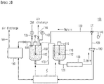
- FIG. 2 is a schematic diagram of an electrode insulating liquid supply apparatus 100 according to a first embodiment of the present invention.
- insulating liquid is supplied to the insulating liquid coating die 140 through the supply line 120 from the storage tank 110 where the predetermined insulating liquid is stored.
- the insulating liquid is composed of about 90% or more of binders and 10% or less of solids, and the viscosity is pretty high (900 to 5,000 cP). When the viscosity is low, the fluidity increases. Hence, it is preferable to lower the viscosity of the insulating liquid as much as possible.
- the viscosity of the insulating liquid is preferably in the range of 900 to 3000 cP.
- the insulating liquid charged in the storage tank 110 is preferably insulating liquid which has been defoamed in advance from the defoaming tank 160, as will be described later.
- the stirring blade 112 for stirring insulating liquid is rotated by the motor 111 in the storage tank 110.
- the predetermined insulating liquid which may be used in the present invention, may be a solution containing a polymer made of one or more selected from the group consisting of polybutadiene, polyurethane, polyimide, acetate, polyester, polyphenylene sulfide, polypropylene, styrene-butadiene-based copolymer, (meta)acrylic acid, (meta)acrylate copolymer, polyacrylonitrile, polyvinyl chloride, polyfluoro compound, polyvinyl alcohol, and polycyanoacrylate; or a monomer used for polymerization of polymer of one or more selected from the group consisting of polybutadiene, polyurethane, polyimide, acetate, polyester, polyphenylene sulfide, polypropylene, styrene-butadiene-based copolymer, (meta)acrylic acid, (meta)acrylate copolymer, polyacrylonitrile, polyvinyl chloride,
- PVdF polyvinylidene fluoride
- ceramic-based insulating liquid e.g., aluminum hydroxide-based insulating liquid such as boehmite
- the insulating liquid may contain one or more solvents selected from the group consisting of water, glycerol, ethylene glycol, propylene glycol, dimethyl sulfoxide, dimethylformamide, acetonitrile, ethylene carbonate, furfuryl alcohol, and methanol.
- the high viscosity insulating liquid of the storage tank 110 is pumped by the pump 130 to be supplied to the coating die 140, and the insulating liquid is discharged by a predetermined nozzle from the coating die 140 to thereby be coated on the surface of the electrode (e.g., a positive electrode).
- the pump 130 may be, for example, a mono pump of a simple structure.
- a mono pump is composed of a stator formed of an elastic body having a spiral tunnel in a pump, and a spiral rotor which is rotated in the stator.
- liquid is consecutively flown from an inlet to a discharge port in an axial direction in the pump.
- a mono pump was mentioned, but any pump capable of appropriately transferring liquid in a supply line in consideration of the viscosity and physical properties of the insulating liquid may be used.
- the defoaming tank 160 is connected to the insulating liquid storage tank 110 by a pipe 170.
- the insulating liquid storage capacity of the defoaming tank 160 may be the same as or different from that of the insulating liquid storage tank 110, but it is preferable that they are the same in terms of the capacity management.
- the insulating liquid may be stirred by rotation of the stirring blade 162 by a motor 161 as in the storage tank 110.
- the number of rotations of the stirring blade 162 may be selected within an appropriate range in order to raise bubbles in the insulating liquid in addition to the insulating liquid stirring.
- Reference numeral 163 refers to a pressure gauge
- reference numeral 164 refers to a discharge line through which bubble-mixed air may be discharged.
- the insulating liquid in the defoaming tank 160 is supplied to the storage tank 110 through a pipe 170 after bubbles are defoamed by the vacuum pump 180 as will be described later.
- the defoaming tank 160 is connected to the vacuum pump 180 by a connection line 181 and may discharge air in the defoaming tank 160 through a discharge line 164 by the power of vacuum.
- the vacuum degree of the vacuum pump 180 may be appropriately adjusted according to the capacity of the defoaming tank 160 and the storage tank 110 and the air flow rate and the amount of bubbles generated in each tank.
- the air which is inevitably injected into the vacuum pump 180 by vacuum suction of the vacuum pump 180 (where bubbles may also be mixed), is discharged to the outside through a discharge line 184 equipped in the vacuum pump 180.
- FIG. 2 shows an example where a direction change valve 121 is installed in a supply line 120 adjacent to the coating die 140, and an insulating liquid return line 150 is installed from the direction change valve 121 to a defoaming tank 160.
- This is an insulating liquid circulation circuit (closed circuit) formed of defoaming tank 160 - insulating liquid storage tank 110 - supply line 120 - (coating die 140) - direction change valve 121 - return line 150.
- the direction change valve 121 may be a 3-way valve, and adjusts the insulating liquid supply from the supply line 120 to the coating die 140, and the insulating liquid flow from the supply line 120 to the return line 150 (when the coating is terminated or is stopped).
- the insulating liquid pipe such as the supply line 120 and the return line 150 is preferably formed of a pipe made of a material having small frictional force with the insulating liquid. Particularly, since the insulating liquid has a large viscosity, it may be difficult to obtain a desired transfer speed when transferred to the coater according to the frictional force with the pipe. Further, the diameter of the pipe is preferably a value which is appropriate for the transfer of a high viscosity insulating liquid. Hence, the material, the diameter, etc. of the pipe may be appropriately decided in consideration of the viscosity and transfer speed of the insulating liquid.
- the insulating liquid may be supplied to the coater at the transfer speed of 0.060 to 0.30 L/min.
- a pipe of 1 inch or higher may be used.
- a pipe made of stainless steel or Teflon, which has a low frictional force with high viscosity insulating liquid, may be used as the pipe.
- the pump pressure of the mono pump is set to an appropriate value in order to achieve the targeted transfer speed of the high viscosity insulating liquid.
- the advantage of the circulation circuit is in being able to defoaming the remaining insulating liquid and reusing it in the insulation coating.
- a predetermined valve, and a branch line (not shown) connected to a drain line are installed at an insulating liquid return line 150 before reaching the defoaming tank 160, the drain of the insulating liquid and the return flow to the defoaming tank 160 may be selectively or simultaneously achieved as necessary.
- valves capable of adjusting the flow rate are installed at the connection line, the pipe, etc. of each element.
- the points about such valves correspond to a general technical matter in the pipe line, and accordingly, the detailed description thereof will be omitted here.
- the main feature of the present invention is in organically connecting bubble measurement with bubble defoamation by installing a bubble sensor 190 capable of sensing the generation status of bubbles in real time in the insulating liquid supply line 120.
- a defoaming system which is composed of a vacuum pump 180 and a defoaming tank 160
- the generation status of bubbles is monitored in real time by installing a bubble sensor 190 in the supply line 120.
- the bubble sensor 190 the amount of bubbles in the supply line was efficiently measured by applying an ultrasonic sensor, as will be described later.
- insulating liquid which has been defoamed in the defoaming tank 160 in advance, is transferred to the storage tank 110, and accordingly, a pin hole defect can be prevented in the coating die 140.
- bubbles may be generated by a fall head in the storage tank 110 during the repeated and consecutive process of coating insulating liquid thereafter, and bubbles may be generated in the supply line 120 by the continuous inflow of air containing impurities from the outside during the pumping process in the pump 120.
- the bubble sensor 190 may sense the amount of bubbles in real time and send the data to the controller C of the insulating liquid supply apparatus 100.
- the controller C may adjust the operating condition of the insulating liquid supply apparatus 100 based on the data about the amount of bubbles.
- "operating condition" of the insulating liquid supply apparatus includes a decision about whether to continue to supply insulating liquid to a supply line (namely, a decision about opening/closing condition of each valve), a temperature or pressure setting condition in the defoaming tank, an operating condition such as the number of rotations of the stirring blade, and a condition value related to operation of each component such as a vacuum degree of the vacuum pump, and is a concept including the overall apparatus operating condition for adjusting the defoaming performance or whether to continue the supply of insulating liquid according to the conditions.
- the controller C may block the direction change valve 121 and stop the supply of the insulating liquid. In this case, the insulating liquid, which contains bubbles exceeding a predetermined value, returns to the defoaming tank 160 through the return line 150 and goes through the defoaming process.
- the amount of bubbles is measured again through the bubble sensor 190, and this process may be repeated until the amount of bubbles decreases to a value equal to or less than the predetermined value. Namely, according to the present invention, it is possible to suppress the pin hole defect by transferring insulating liquid having bubbles equal to or less than a predetermined amount to the coating die.
- the amount of bubbles sensed by the bubble sensor 190 exceeds a predetermined value or if the amount of bubbles tends to increase even when within a predetermined value, it is possible to reinforce the defoaming performance by improving the vacuum degree of the vacuum pump 180, which is one of operating conditions of the apparatus. Alternatively, it is possible to strengthen the air discharge in the defoaming tank 160 by increasing the number of rotations of the stirring blade 162 installed at the defoaming tank 160.
- the present invention it is possible to control the defoaming degree of the insulating liquid in real time by monitoring the amount of bubbles in the supply line in real time and adjusting the operating conditions of the insulating liquid supply apparatus 100 based on the monitored data in response to operating situations of an apparatus and various variables.
- FIG. 2 a second embodiment of the present invention will also be described.
- clean dry air is supplied through the supply line 165 of the CDA in order to transfer the insulating liquid in the defoaming tank 160 to the storage tank 110.
- CDA clean dry air
- a separate pump in a pipe 170, which connects the defoaming tank 160 to the storage tank 110, as in a pump 130 installed at the supply line 120 of the insulating liquid supply apparatus 100.
- transfer by a pump has a danger that bubbles may be mixed.
- insulating liquid is transferred by applying pressure with CDA instead of a pump.
- the clean dry air system is a system which supplies optimal compressed air by filtering contaminants such as dust, oil, and moisture to be within a predetermined level based on the requirements.
- the present invention it is possible to efficiently transfer insulating liquid defoamed in the defoaming tank 160 to the storage tank 110 by using compressed air (CDA) of the clean dry air system. Strictly speaking, the insulating liquid in the defoaming tank 160 is transferred to the storage tank 110 by the resultant force of the pressure of the CDA and the potential energy by a fall head within the defoaming tank 160.
- CDA compressed air
- R denotes a regulator which allows CDA to be transferred with a constant pressure.
- the insulating liquid has a high viscosity as described above, if the pressure of the CDA is appropriately set, it is possible to prevent generation of bubbles as the CDA is dissolved in the insulating liquid. Namely, it is important to set the pressure of the clean dry air (CDA) to be in a range in which it is not dissolved in consideration of viscosity of the insulating liquid in the operating condition of the defoaming tank (e.g., temperature and pressure in the defoaming tank).
- CDA clean dry air
- the pressure of the CDA is set to 2 MPa, the CDA is rarely dissolved in the insulating liquid.
- a pressure of at least 0.3 MPa is necessary.
- the pressure is preferably equal to or less than 1 MPa, and more preferably in the range of 0.5 to 0.7 MPa.
- N 2 is appropriate as CDA media of the pressure because it has a low chemical activity and a low solubility to water at a low pressure.
- transferring insulating liquid with CDA has an advantage that the insulating liquid can be appropriately transferred while preventing the danger of generation of bubbles by a pump.
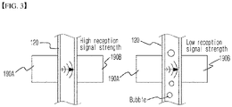
- FIG. 3 is a schematic diagram of an ultrasonic sensor 190 used in an electrode insulating liquid supply apparatus 100 of the present invention. Namely, in the present embodiment, an ultrasonic sensor is used as the bubble sensor 190.
- the ultrasonic sensor 190 of the present example is composed of a transmitting sensor 190A (piezoelectric sensor) installed at one side of the tube of the supply line 120, and a receiving sensor 190B (piezoelectric sensor) installed at the other side of the tube, and has a structure in which the bubble generation status is sensed by the strength of the ultrasonic waves transmitted from the transmitting sensor 190A. Namely, if ultrasonic waves are generated by applying a voltage to the transmitting sensor 190A, the ultrasonic waves pass through the tube and are sensed by the receiving sensor 190B. When there is no or only a few bubbles (see the left figure of FIG.
- the strength of the ultrasonic waves sensed by the receiving sensor 190B increases, which is detected as a greater voltage in the receiving sensor 190B. If the number of bubbles is large (see the right figure of FIG. 3 ), the strength of the ultrasonic waves decreases, which is detected as a smaller voltage in the receiving sensor 190B.
- the apparatus of the third embodiment it is possible to sense and monitor the number or amount of bubbles generated in the insulating liquid in the supply line 120 by an ultrasonic sensor composed of 2 sensors 190A and 190B in real time.
- an ultrasonic sensor was composed of 2 sensors, but the number of transmitting and receiving sensors is not particularly limited, and two or more sensors may be applied as long as each of the sensors can efficiently measure the bubbles in the tube of the supply line 120.
- the ultrasonic sensor can efficiently measure the number of bubbles in a non-contact manner by using an ultrasonic sensor.
- the ultrasonic sensor is more preferable than other kinds of sensors in terms of contamination prevention of the insulating liquid.
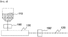
- FIG. 4 is a schematic diagram of an electrode insulating liquid supply apparatus 100 according to another embodiment of the present invention.
- a plurality of ultrasonic sensors are installed at the position where frequency of bubble generation of the supply line is high.
- ultrasonic sensors 190 and 190' were installed in the supply line 120 between the lower portion of the storage tank 110 and the pump 130, and the supply line 120 after the pump 130, respectively, according to the number of places where bubbles were generated.
- the defoaming situation of the electrode insulating liquid supplying apparatus of the present invention was compared with the conventional electrode insulating liquid supplying apparatus in consideration of the mass production situation of the electrode based on each of the above embodiments.
- PVdF insulating liquid which was obtained by dissolving 7% PVdF solids in an NMP solvent, was poured in the storage tank in the same manner as in the mass production, and 200 L of PVdF insulating liquid was also poured in the defoaming tank, and a defoaming process was then performed for 12 hours at the vacuum degree of the vacuum pump of 0.35 MPa.
- the viscosity of the PVdF insulating liquid is in the range of 2,000 to 3,000 cP.
- the amount of insulating liquid was set to 200 L, but the amount of insulating liquid may be selected in the range of 100 to 200 L, depending on the production condition. In some cases, it is possible to select a more amount of insulating liquid.
- the present invention relates to an insulating liquid supply apparatus capable of monitoring generation of bubbles in real time and efficiently defoaming bubbles according to the bubble generation status.
- the present invention may be understood as a method for supplying insulating liquid to form an insulation coating layer on an electrode.
- a method of supplying insulating liquid of the present invention includes: defoaming bubbles of the insulating liquid by applying vacuum to a defoaming tank where a predetermined amount of insulating liquid is stored; transferring the defoamed insulating liquid from the defoaming tank to a storage tank; forming an insulating coating layer with the defoamed insulating liquid on an electrode at a coating die by transferring the insulating liquid of the storage tank to the coating die through a supply line; and adjusting an operating condition of an apparatus for supplying insulating liquid based on an amount of bubbles sensed by a bubble sensor by sensing bubbles in the supply line using the bubble sensor during transfer of the insulating liquid through the supply line.
- the insulating liquid supplying method of the present invention it is possible to more effectively improve the quality of an insulating coating layer by suppressing generation of bubbles while monitoring the bubble generation status in real time.
Landscapes
- Chemical & Material Sciences (AREA)
- Chemical Kinetics & Catalysis (AREA)
- Electrochemistry (AREA)
- General Chemical & Material Sciences (AREA)
- Engineering & Computer Science (AREA)
- Manufacturing & Machinery (AREA)
- Dispersion Chemistry (AREA)
- Degasification And Air Bubble Elimination (AREA)
- Coating Apparatus (AREA)
Abstract
Description
- The present invention relates to an apparatus for supplying insulating liquid to an electrode for a battery and a method for supplying the insulating liquid.
- This application claims the benefit of priority based on
Korean Patent Application No. 10-2020-0138326 filed on October 23, 2020 Korean Patent Application No. 10-2021-0131148 filed on October 1, 2021 - With the increase in technology development and demand for mobile devices, the demand for secondary batteries is also rapidly increasing. Among them, lithium secondary batteries are widely used as an energy source for various electronic products as well as various mobile devices because of their high energy density and high operating voltage and excellent storage and lifetime characteristics.
- One of the major research tasks in these secondary batteries is to improve safety. Battery safety related accidents are closely related with abnormal high temperature conditions due to a short circuit between a positive electrode and a negative electrode. Namely, in a normal situation, a separator is positioned between a positive electrode and a negative electrode, to thereby maintain electrical insulation, but in an abnormal situation where a battery is overcharged or overdischarged, an internal short circuit occurs due to dendritic growth of an electrode material, or a foreign material, a sharp object such as nail, screws, etc. penetrates a battery, or a battery is deformed by external force, the existing separator is not sufficient.
- Further, the separator, which is mainly formed of a microporous membrane made of a polyolefin resin, has a heat resistance temperature of about 120 to 160°C, which is not a sufficient heat resistance. Hence, when an internal short circuit occurs, the separator shrinks due to the short circuit reaction heat and the short circuit occurs in a larger area, which leads to a thermal runaway state where more reaction heat is generated.
- Hence, in order to reduce the possibility of a short circuit of the positive electrode and the negative electrode by maintaining the insulation of the battery electrode, the devising of a method for coating an insulating liquid on the portion of the positive electrode is in progress.
-
FIG. 1 is a conceptual diagram of a conventional electrode insulating liquid supply apparatus. As illustrated, insulating liquid is supplied to the insulating liquid coating die 40 through thesupply line 20 from thestorage tank 10 where the predetermined insulating liquid is stored. The insulating liquid having a high viscosity is pumped by apump 30 to thereby be supplied to acoating die 40, and the insulating liquid is discharged by a nozzle from thecoating die 40 to then be coated on the surface of the positive electrode. When the coating is completed, the insulating liquid of the supply line is returned to thestorage tank 10 through thereturn line 50 by thedirection change valve 21. - However, the bubbles are inevitably mixed in the insulating liquid in the supply line, which is supplied to the conventional electrode insulating liquid supply apparatus. It is estimated that the bubbles are generated by a fall head when insulating liquid is put in the
storage tank 10, or is generated by pores in thepump 30 installed in thesupply line 20, pores between thesupply line 20 and thepump 30, and leakage. - If bubbles are generated in the insulating liquid transferred to the supply line, a pin hole defect, in which pin holes are generated at positions where bubbles have been evaporated at the time of heat-drying after coating an insulating layer by a coating die, is generated. The pin hole defect gives adverse effects to the insulating nature of the electrode, which makes it difficult to reach the designed electrode insulation performance and increases a danger of a short circuit between electrodes.
- Therefore, there is a need for a technology of suppressing a pin hole defect by removing bubbles in insulating liquid when supplying the insulating liquid to an electrode.
- Further, a technology of defoaming bubbles in an electrode slurry when coating an electrode slurry, which is not insulating liquid, on a current collector has been proposed. However, forms of insulating liquid and the electrode slurry are different because the insulating liquid is liquid and the electrode slurry is a slurry, and their physical properties such as viscosity are also different. Therefore, there is a limit in applying a defoaming device of an electrode slurry at the time of defoaming insulating liquid.
- Further, even when considering application of the defoaming technology of the electrode slurry at the time of defoaming insulating liquid, if the level of bubbles in the
supply line 20 is not recognized, bubbles may be insufficiently defoamed or excessively defoamed. Namely, even when the insulating liquid in thestorage tank 10 can be mechanically defoamed, if the level of bubbles is not carefully monitored, it may be difficult to prevent generation of a pin hole in acoating die 40. - Hence, there is a need for a technology for appropriately recognizing the level of bubbles in a supply line and applying the information to the defoaming process.
-
Korean Patent No. 10-2035822 - The present invention is believed to solve at least some of the above problems. For example, an aspect of the present invention provides an electrode insulating liquid supplying apparatus and method for removing bubbles generated at the time of supplying insulating liquid to an electrode.
- Further, another aspect of the present invention provides an electrode insulating liquid supplying apparatus and method for efficiently removing bubbles by measuring bubbles generated in a supply line in real time at the time of supplying insulating liquid to an electrode.
- An apparatus for supplying insulating liquid for forming an insulation coating layer on an electrode for solving the above problems includes: a storage tank where insulating liquid is stored; a coating die where the insulating liquid is coated on an electrode; a supply line which is connected to the storage tank and supplies the insulating liquid to the coating die; a pump which is installed on the supply line; a defoaming tank which is connected to the storage tank and supplies defoamed insulating liquid to the storage tank; a vacuum pump which defoams bubbles of the insulating liquid in the defoaming tank by applying vacuum to the defoaming tank; a bubble sensor which is installed on the supply line and senses generation of bubbles in the supply line in real time; and a controller which adjusts an operating condition of the apparatus based on an amount of bubbles sensed by the bubble sensor.
- In one example, the controller may control to supply the insulating liquid to the coating die if the amount of bubbles sensed by the bubble sensor is equal to or less than a predetermined value, and control to stop supply of the insulating liquid to the coating die if the amount of bubbles sensed by the bubble sensor exceeds the predetermined value.
- Alternatively, the controller may adjust the vacuum degree of the vacuum pump or the number of rotations of stirring blades installed at the defoaming tank according to the amount of bubbles sensed by the bubble sensor.
- In one example, the apparatus may further include an insulating liquid return line which returns the insulating liquid from the supply line to the defoaming tank by a direction change valve.
- In one preferred example of the present invention, clean dry air (CDA) of a predetermined pressure may be supplied into the defoaming tank, and the insulating liquid in the defoaming tank may be transferred to the storage tank by a pressure of the clean dry air.
- Specifically, the pressure of the clean dry air may be set to be in a range in which the clean dry air is not dissolved in the insulating liquid in consideration of viscosity of the insulating liquid under an operating condition of the defoaming tank. In one example, the pressure of the clean dry air is in a range of 0.3 to 2 MPa. In a specific example, the clean dry air may be nitrogen.
- Preferably, the bubble sensor is an ultrasonic sensor. Further, at least one bubble sensor may be installed at a position where a frequency of bubble generation of the supply line is high.
- Further, the present invention provides a method for supplying insulating liquid to form an insulation coating layer on an electrode. In one example, the method for supplying insulating liquid of the present invention includes: defoaming bubbles of the insulating liquid by applying vacuum to a defoaming tank where a predetermined amount of insulating liquid is stored; transferring the defoamed insulating liquid from the defoaming tank to a storage tank; and forming an insulating coating layer with the defoamed insulating liquid on an electrode at a coating die by transferring the insulating liquid of the storage tank to the coating die through a supply line. Particularly, the method may further include adjusting an operating condition of an apparatus for supplying insulating liquid based on an amount of bubbles sensed by a bubble sensor by sensing bubbles in the supply line using the bubble sensor during transfer of the insulating liquid through the supply line.
- According to an electrode insulating liquid supplying apparatus and method of the present invention, it is possible to reduce the pin hole defect of an insulation coating layer by suppressing bubbles in the insulating liquid supply line as much as possible.
- Further, it is possible to monitor the level of generation of bubbles in the supply line in real time by installing a bubble sensor in the insulating liquid supply line, thereby more efficiently removing bubbles.
-
-
FIG. 1 is a conceptual diagram of a conventional electrode insulating liquid supply apparatus. -
FIG. 2 is a schematic diagram of an electrode insulating liquid supply apparatus according to one embodiment of the present invention. -
FIG. 3 is a schematic diagram of an ultrasonic sensor used in an electrode insulating liquid supply apparatus of the present invention. -
FIG. 4 is a schematic diagram of an electrode insulating liquid supply apparatus according to another embodiment of the present invention. - Hereinafter, the detailed configuration of the present invention will be described in detail with reference to the accompanying drawings and various embodiments. Embodiments described below are exemplary to assist in understanding of the present invention, and in order to help understand the invention, the accompanying drawings are not shown as actual scale and the dimensions of some components may be exaggerated.
- As the inventive concept allows for various changes and numerous embodiments, particular embodiments will be illustrated in the drawings and described in detail in the text. However, this is not intended to limit the present invention to the specific form disclosed, and it should be understood to include all changes, equivalents, and substitutes included in the spirit and scope of the present invention.
- The present invention provides an apparatus for supplying insulating liquid for forming an insulation coating layer on an electrode.
- An apparatus for supplying insulating liquid of the present invention includes: a storage tank where insulating liquid is stored; a coating die where the insulating liquid is coated on an electrode; a supply line which is connected to the storage tank and supplies the insulating liquid to the coating die; a pump which is installed on the supply line; a defoaming tank which is connected to the storage tank and supplies defoamed insulating liquid to the storage tank; a vacuum pump which defoams bubbles of the insulating liquid in the defoaming tank by applying vacuum to the defoaming tank; a bubble sensor which is installed on the supply line and senses generation of bubbles in the supply line in real time; and a controller which adjusts an operating condition of the apparatus based on an amount of bubbles sensed by the bubble sensor.
- One of the features of the present invention is in allowing mutual connection by installing a defoaming tank for defoaming bubbles separately from the insulating liquid storage tank in an electrode insulating liquid supplying apparatus. Since a general insulating liquid storage tank structurally has a limit in the airtightness, defoaming bubbles by directly connecting a vacuum pump to the insulating liquid storage tank is not efficient. Further, a discharge line for discharging air at the defoaming, and a connection line with a vacuum pump should be in a tank, and it is difficult to install complicated lines in terms of the structure of the conventional storage tank.
- Hence, in the present invention, a separate defoaming tank, which has airtightness and is easy to be installed, is installed and is connected to a storage tank. Further, when a defoaming tank and a storage tank are separately installed, the number of tanks capable of storing insulating liquid becomes 2, and accordingly, the insulating liquid storage capacity increases, and the flow rate and capacity of the insulating liquid of the defoaming tank and the storage tank can be appropriately controlled. In some cases, if a plurality of defoaming tanks are connected to the storage tank, the capacity of the storage tank can increase.
-
FIG. 2 is a schematic diagram of an electrode insulatingliquid supply apparatus 100 according to a first embodiment of the present invention. - As illustrated, insulating liquid is supplied to the insulating liquid coating die 140 through the
supply line 120 from thestorage tank 110 where the predetermined insulating liquid is stored. The insulating liquid is composed of about 90% or more of binders and 10% or less of solids, and the viscosity is pretty high (900 to 5,000 cP). When the viscosity is low, the fluidity increases. Hence, it is preferable to lower the viscosity of the insulating liquid as much as possible. The viscosity of the insulating liquid is preferably in the range of 900 to 3000 cP. The insulating liquid charged in thestorage tank 110 is preferably insulating liquid which has been defoamed in advance from thedefoaming tank 160, as will be described later. Thestirring blade 112 for stirring insulating liquid is rotated by themotor 111 in thestorage tank 110. - The predetermined insulating liquid, which may be used in the present invention, may be a solution containing a polymer made of one or more selected from the group consisting of polybutadiene, polyurethane, polyimide, acetate, polyester, polyphenylene sulfide, polypropylene, styrene-butadiene-based copolymer, (meta)acrylic acid, (meta)acrylate copolymer, polyacrylonitrile, polyvinyl chloride, polyfluoro compound, polyvinyl alcohol, and polycyanoacrylate; or a monomer used for polymerization of polymer of one or more selected from the group consisting of polybutadiene, polyurethane, polyimide, acetate, polyester, polyphenylene sulfide, polypropylene, styrene-butadiene-based copolymer, (meta)acrylic acid, (meta)acrylate copolymer, polyacrylonitrile, polyvinyl chloride, polyfluoro compound, polyvinyl alcohol, and polycyanoacrylate.
- Specifically, polyvinylidene fluoride (PVdF)-based insulating liquid, ceramic-based insulating liquid (e.g., aluminum hydroxide-based insulating liquid such as boehmite) may be used.
- The insulating liquid may contain one or more solvents selected from the group consisting of water, glycerol, ethylene glycol, propylene glycol, dimethyl sulfoxide, dimethylformamide, acetonitrile, ethylene carbonate, furfuryl alcohol, and methanol.
- The high viscosity insulating liquid of the
storage tank 110 is pumped by thepump 130 to be supplied to the coating die 140, and the insulating liquid is discharged by a predetermined nozzle from the coating die 140 to thereby be coated on the surface of the electrode (e.g., a positive electrode). Thepump 130 may be, for example, a mono pump of a simple structure. A mono pump is composed of a stator formed of an elastic body having a spiral tunnel in a pump, and a spiral rotor which is rotated in the stator. Herein, if the rotor is rotated in the stator, liquid is consecutively flown from an inlet to a discharge port in an axial direction in the pump. In the present specification, a mono pump was mentioned, but any pump capable of appropriately transferring liquid in a supply line in consideration of the viscosity and physical properties of the insulating liquid may be used. - In the present embodiment, the
defoaming tank 160 is connected to the insulatingliquid storage tank 110 by apipe 170. The insulating liquid storage capacity of thedefoaming tank 160 may be the same as or different from that of the insulatingliquid storage tank 110, but it is preferable that they are the same in terms of the capacity management. In thedefoaming tank 160, the insulating liquid may be stirred by rotation of thestirring blade 162 by a motor 161 as in thestorage tank 110. The number of rotations of thestirring blade 162 may be selected within an appropriate range in order to raise bubbles in the insulating liquid in addition to the insulating liquid stirring. Reference numeral 163 refers to a pressure gauge, andreference numeral 164 refers to a discharge line through which bubble-mixed air may be discharged. The insulating liquid in thedefoaming tank 160 is supplied to thestorage tank 110 through apipe 170 after bubbles are defoamed by thevacuum pump 180 as will be described later. - The
defoaming tank 160 is connected to thevacuum pump 180 by aconnection line 181 and may discharge air in thedefoaming tank 160 through adischarge line 164 by the power of vacuum. - The vacuum degree of the
vacuum pump 180 may be appropriately adjusted according to the capacity of thedefoaming tank 160 and thestorage tank 110 and the air flow rate and the amount of bubbles generated in each tank. - The air, which is inevitably injected into the
vacuum pump 180 by vacuum suction of the vacuum pump 180 (where bubbles may also be mixed), is discharged to the outside through adischarge line 184 equipped in thevacuum pump 180. -
FIG. 2 shows an example where adirection change valve 121 is installed in asupply line 120 adjacent to the coating die 140, and an insulatingliquid return line 150 is installed from thedirection change valve 121 to adefoaming tank 160. This is an insulating liquid circulation circuit (closed circuit) formed of defoaming tank 160 - insulating liquid storage tank 110 - supply line 120 - (coating die 140) - direction change valve 121 -return line 150. - The
direction change valve 121, for example, may be a 3-way valve, and adjusts the insulating liquid supply from thesupply line 120 to the coating die 140, and the insulating liquid flow from thesupply line 120 to the return line 150 (when the coating is terminated or is stopped). - The insulating liquid pipe such as the
supply line 120 and thereturn line 150 is preferably formed of a pipe made of a material having small frictional force with the insulating liquid. Particularly, since the insulating liquid has a large viscosity, it may be difficult to obtain a desired transfer speed when transferred to the coater according to the frictional force with the pipe. Further, the diameter of the pipe is preferably a value which is appropriate for the transfer of a high viscosity insulating liquid. Hence, the material, the diameter, etc. of the pipe may be appropriately decided in consideration of the viscosity and transfer speed of the insulating liquid. For example, if the viscosity of the insulating liquid is in the range of 900 to 5000 cP, the insulating liquid may be supplied to the coater at the transfer speed of 0.060 to 0.30 L/min. In this case, for example, a pipe of 1 inch or higher may be used. Further, a pipe made of stainless steel or Teflon, which has a low frictional force with high viscosity insulating liquid, may be used as the pipe. - Further, it is preferable to set the pump pressure of the mono pump to an appropriate value in order to achieve the targeted transfer speed of the high viscosity insulating liquid.
- The advantage of the circulation circuit is in being able to defoaming the remaining insulating liquid and reusing it in the insulation coating. Herein, if a predetermined valve, and a branch line (not shown) connected to a drain line are installed at an insulating
liquid return line 150 before reaching thedefoaming tank 160, the drain of the insulating liquid and the return flow to thedefoaming tank 160 may be selectively or simultaneously achieved as necessary. - Since such a valve configuration is equipped in a general insulating liquid supply device, too, the detailed description of the function and action will be omitted here.
- Referring to
FIG. 2 , other valves capable of adjusting the flow rate are installed at the connection line, the pipe, etc. of each element. Herein, the points about such valves correspond to a general technical matter in the pipe line, and accordingly, the detailed description thereof will be omitted here. - The main feature of the present invention is in organically connecting bubble measurement with bubble defoamation by installing a
bubble sensor 190 capable of sensing the generation status of bubbles in real time in the insulatingliquid supply line 120. - It is possible to efficiently reuse insulating liquid and maintain the level of bubbles of the insulating liquid in the
supply line 120 constant by operating a defoaming system, which is composed of avacuum pump 180 and adefoaming tank 160, by a controller C to transfer defoamed insulating liquid to thestorage tank 110, or defoam insulating liquid, which returns to thedefoaming tank 160, and transfer the defoamed insulating liquid to thestorage tank 110. However, if the level of the bubbles in thesupply line 120 is not recognized, the bubbles may not be sufficiently defoamed or may be excessively defoamed. - Hence, in the present invention, the generation status of bubbles is monitored in real time by installing a
bubble sensor 190 in thesupply line 120. In the present invention, as a specific example of thebubble sensor 190, the amount of bubbles in the supply line was efficiently measured by applying an ultrasonic sensor, as will be described later. - Specifically, in the initial period of the operation of the insulating
liquid supply apparatus 100, insulating liquid, which has been defoamed in thedefoaming tank 160 in advance, is transferred to thestorage tank 110, and accordingly, a pin hole defect can be prevented in the coating die 140. However, bubbles may be generated by a fall head in thestorage tank 110 during the repeated and consecutive process of coating insulating liquid thereafter, and bubbles may be generated in thesupply line 120 by the continuous inflow of air containing impurities from the outside during the pumping process in thepump 120. Thebubble sensor 190 may sense the amount of bubbles in real time and send the data to the controller C of the insulatingliquid supply apparatus 100. The controller C may adjust the operating condition of the insulatingliquid supply apparatus 100 based on the data about the amount of bubbles. In the present specification, "operating condition" of the insulating liquid supply apparatus includes a decision about whether to continue to supply insulating liquid to a supply line (namely, a decision about opening/closing condition of each valve), a temperature or pressure setting condition in the defoaming tank, an operating condition such as the number of rotations of the stirring blade, and a condition value related to operation of each component such as a vacuum degree of the vacuum pump, and is a concept including the overall apparatus operating condition for adjusting the defoaming performance or whether to continue the supply of insulating liquid according to the conditions. Likewise, according to the present invention, it is possible to effectively suppress pin hole generation of the insulating coating layer by organically adjusting the operation of the insulatingliquid supply apparatus 100 based on the value of the amount of bubbles measured by the bubble sensor. - Specifically, it is possible to set data about the amount of bubbles of a predetermined range, where a pin hole defect occurs, in advance, and adjust the operating condition of the apparatus by comparing the data with the amount of bubbles measured by the bubble sensor. If the amount of bubbles sensed by the bubble sensor is equal to or less than a predetermined value, the supplying of the insulating liquid to the coating die is continued, but if the amount of bubbles sensed by the bubble sensor exceeds the predetermined value, the controller C may block the
direction change valve 121 and stop the supply of the insulating liquid. In this case, the insulating liquid, which contains bubbles exceeding a predetermined value, returns to thedefoaming tank 160 through thereturn line 150 and goes through the defoaming process. In the insulating liquid, which has been supplied to thesupply line 120 again via thestorage tank 110 after the defoamation, the amount of bubbles is measured again through thebubble sensor 190, and this process may be repeated until the amount of bubbles decreases to a value equal to or less than the predetermined value. Namely, according to the present invention, it is possible to suppress the pin hole defect by transferring insulating liquid having bubbles equal to or less than a predetermined amount to the coating die. - Further, even if the amount of bubbles sensed by the
bubble sensor 190 exceeds a predetermined value or if the amount of bubbles tends to increase even when within a predetermined value, it is possible to reinforce the defoaming performance by improving the vacuum degree of thevacuum pump 180, which is one of operating conditions of the apparatus. Alternatively, it is possible to strengthen the air discharge in thedefoaming tank 160 by increasing the number of rotations of thestirring blade 162 installed at thedefoaming tank 160. - In summary, according to the present invention, it is possible to control the defoaming degree of the insulating liquid in real time by monitoring the amount of bubbles in the supply line in real time and adjusting the operating conditions of the insulating
liquid supply apparatus 100 based on the monitored data in response to operating situations of an apparatus and various variables. - Referring to
FIG. 2 , a second embodiment of the present invention will also be described. - In the present embodiment, clean dry air (CDA) is supplied through the supply line 165 of the CDA in order to transfer the insulating liquid in the
defoaming tank 160 to thestorage tank 110. Herein, it is possible to transfer insulating liquid defoamed in thedefoaming tank 160 to thestorage tank 110 by installing a separate pump in apipe 170, which connects thedefoaming tank 160 to thestorage tank 110, as in apump 130 installed at thesupply line 120 of the insulatingliquid supply apparatus 100. However, when considering that it is estimated that one of main reasons of bubble generation is pores and leakage, transfer by a pump has a danger that bubbles may be mixed. Hence, in the present embodiment, insulating liquid is transferred by applying pressure with CDA instead of a pump. The clean dry air system is a system which supplies optimal compressed air by filtering contaminants such as dust, oil, and moisture to be within a predetermined level based on the requirements. - In the present invention, it is possible to efficiently transfer insulating liquid defoamed in the
defoaming tank 160 to thestorage tank 110 by using compressed air (CDA) of the clean dry air system. Strictly speaking, the insulating liquid in thedefoaming tank 160 is transferred to thestorage tank 110 by the resultant force of the pressure of the CDA and the potential energy by a fall head within thedefoaming tank 160. - In
FIG. 2 , R denotes a regulator which allows CDA to be transferred with a constant pressure. - Since the insulating liquid has a high viscosity as described above, if the pressure of the CDA is appropriately set, it is possible to prevent generation of bubbles as the CDA is dissolved in the insulating liquid. Namely, it is important to set the pressure of the clean dry air (CDA) to be in a range in which it is not dissolved in consideration of viscosity of the insulating liquid in the operating condition of the defoaming tank (e.g., temperature and pressure in the defoaming tank). When considering the insulating liquid having a viscosity in a range of 900 to 5000 cP under the operating condition of the used defoaming tank, if the pressure of the CDA is set to 2 MPa, the CDA is rarely dissolved in the insulating liquid. In order to transfer insulating liquid, a pressure of at least 0.3 MPa is necessary. The pressure is preferably equal to or less than 1 MPa, and more preferably in the range of 0.5 to 0.7 MPa.
- Alternatively, if nitrogen is used as CDA, it is possible to more effectively block dissolution in the insulating liquid. N2 is appropriate as CDA media of the pressure because it has a low chemical activity and a low solubility to water at a low pressure. Likewise, in the present invention, transferring insulating liquid with CDA has an advantage that the insulating liquid can be appropriately transferred while preventing the danger of generation of bubbles by a pump.
-
FIG. 3 is a schematic diagram of anultrasonic sensor 190 used in an electrode insulatingliquid supply apparatus 100 of the present invention. Namely, in the present embodiment, an ultrasonic sensor is used as thebubble sensor 190. - As illustrated in
FIG. 3 , theultrasonic sensor 190 of the present example is composed of a transmittingsensor 190A (piezoelectric sensor) installed at one side of the tube of thesupply line 120, and a receivingsensor 190B (piezoelectric sensor) installed at the other side of the tube, and has a structure in which the bubble generation status is sensed by the strength of the ultrasonic waves transmitted from the transmittingsensor 190A. Namely, if ultrasonic waves are generated by applying a voltage to the transmittingsensor 190A, the ultrasonic waves pass through the tube and are sensed by the receivingsensor 190B. When there is no or only a few bubbles (see the left figure ofFIG. 3 ), the strength of the ultrasonic waves sensed by the receivingsensor 190B increases, which is detected as a greater voltage in the receivingsensor 190B. If the number of bubbles is large (see the right figure ofFIG. 3 ), the strength of the ultrasonic waves decreases, which is detected as a smaller voltage in the receivingsensor 190B. - Likewise, in the apparatus of the third embodiment, it is possible to sense and monitor the number or amount of bubbles generated in the insulating liquid in the
supply line 120 by an ultrasonic sensor composed of 2sensors - In the above example, an ultrasonic sensor was composed of 2 sensors, but the number of transmitting and receiving sensors is not particularly limited, and two or more sensors may be applied as long as each of the sensors can efficiently measure the bubbles in the tube of the
supply line 120. The ultrasonic sensor can efficiently measure the number of bubbles in a non-contact manner by using an ultrasonic sensor. Hence, the ultrasonic sensor is more preferable than other kinds of sensors in terms of contamination prevention of the insulating liquid. -
FIG. 4 is a schematic diagram of an electrode insulatingliquid supply apparatus 100 according to another embodiment of the present invention. - In the present embodiment, a plurality of ultrasonic sensors are installed at the position where frequency of bubble generation of the supply line is high.
- Namely, since it is estimated that bubbles are generated by a fall head at the time of pouring insulating liquid in the
storage tank 110 or are generated by pores and leakage at the time of passing through a pump,ultrasonic sensors 190 and 190' were installed in thesupply line 120 between the lower portion of thestorage tank 110 and thepump 130, and thesupply line 120 after thepump 130, respectively, according to the number of places where bubbles were generated. - As such, it is possible to prevent pin hole defect generation by efficiently recognizing the bubble generation situation and mechanism in the supply line and making a database based thereon by clarifying the number of places of generation of bubbles in the insulating liquid and monitoring the bubble generation situation in each position.
- The defoaming situation of the electrode insulating liquid supplying apparatus of the present invention was compared with the conventional electrode insulating liquid supplying apparatus in consideration of the mass production situation of the electrode based on each of the above embodiments.
- 200 L of PVdF insulating liquid, which was obtained by dissolving 7% PVdF solids in an NMP solvent, was poured in the storage tank in the same manner as in the mass production, and 200 L of PVdF insulating liquid was also poured in the defoaming tank, and a defoaming process was then performed for 12 hours at the vacuum degree of the vacuum pump of 0.35 MPa. The viscosity of the PVdF insulating liquid is in the range of 2,000 to 3,000 cP. In the present embodiment, the amount of insulating liquid was set to 200 L, but the amount of insulating liquid may be selected in the range of 100 to 200 L, depending on the production condition. In some cases, it is possible to select a more amount of insulating liquid.
- In a comparative example, 200 L of PVdF insulating liquid, which was the same as that in the example, was poured in the storage tank of the conventional electrode insulating liquid supplying apparatus where a defoaming tank has not been installed, which was left for 12 hours, and the status of bubble generation was checked.
- As a result of measuring the number of bubbles in a specific portion of the supply line after performing a pumping process by the ultrasonic sensor after 12 hours, 150 bubbles were generated in the case of the comparative example, but the number of bubbles decreased by 96% in the case of the example of the present invention.
- As described above, the present invention relates to an insulating liquid supply apparatus capable of monitoring generation of bubbles in real time and efficiently defoaming bubbles according to the bubble generation status.
- Further, the present invention may be understood as a method for supplying insulating liquid to form an insulation coating layer on an electrode.
- A method of supplying insulating liquid of the present invention includes: defoaming bubbles of the insulating liquid by applying vacuum to a defoaming tank where a predetermined amount of insulating liquid is stored; transferring the defoamed insulating liquid from the defoaming tank to a storage tank; forming an insulating coating layer with the defoamed insulating liquid on an electrode at a coating die by transferring the insulating liquid of the storage tank to the coating die through a supply line; and adjusting an operating condition of an apparatus for supplying insulating liquid based on an amount of bubbles sensed by a bubble sensor by sensing bubbles in the supply line using the bubble sensor during transfer of the insulating liquid through the supply line.
- According to the insulating liquid supplying method of the present invention, it is possible to more effectively improve the quality of an insulating coating layer by suppressing generation of bubbles while monitoring the bubble generation status in real time.
- In the above, the present invention has been described in more detail through the drawings and examples. Accordingly, the embodiments described in the specification and the configurations described in the drawings are only the most preferred embodiments of the present invention, and do not represent all of the technical ideas of the present invention. It is to be understood that there may be various equivalents and variations in place of them at the time of filing the present application.
-
- 100: insulating liquid supply apparatus
- 10, 110: (insulating liquid) storage tank
- 20, 120: supply line
- 21, 121: direction change valve
- 30, 130: pump
- 40, 140: coating die
- 50, 150: insulating liquid return line
- 160: defoaming tank
- 161: stirring motor
- 162: stirring blade
- 163: pressure gauge
- 164: discharge line
- 165: CDA supply line
- 170: pipe
- 180: vacuum pump
- 181: connection line
- 184: discharge line
- 190, 190': bubble sensor (ultrasonic sensor)
- 190A: transmitting sensor
- 190B: receiving sensor
- C: controller
Claims (17)
- An apparatus for supplying insulating liquid for forming an insulation coating layer on an electrode, the apparatus comprising:a storage tank where the insulating liquid is stored;a coating die where the insulating liquid is coated on an electrode;a supply line which is connected to the storage tank and supplies the insulating liquid to the coating die;a pump which is installed on the supply line;a defoaming tank which is connected to the storage tank and supplies defoamed insulating liquid to the storage tank;a vacuum pump which defoams bubbles of the insulating liquid in the defoaming tank by applying vacuum to the defoaming tank;a bubble sensor which is installed on the supply line and senses generation of bubbles in the supply line in real time; anda controller which adjusts an operating condition of the apparatus based on an amount of bubbles sensed by the bubble sensor.
- The apparatus of claim 1, wherein the controller controls to supply the insulating liquid to the coating die if the amount of bubbles sensed by the bubble sensor is equal to or less than a predetermined value, and controls to stop supply of the insulating liquid to the coating die if the amount of bubbles sensed by the bubble sensor exceeds the predetermined value.
- The apparatus of claim 1, wherein the controller adjusts a vacuum degree of the vacuum pump according to the amount of bubbles sensed by the bubble sensor.
- The apparatus of claim 1, wherein a predetermined stirring member is installed at the defoaming tank.
- The apparatus of claim 4, wherein the controller adjusts a number of rotations of stirring blades installed at the defoaming tank according to the amount of bubbles sensed by the bubble sensor.
- The apparatus of claim 1, further comprising an insulating liquid return line which returns the insulating liquid from the supply line to the defoaming tank by a direction change valve.
- The apparatus of claim 1, wherein clean dry air (CDA) of a predetermined pressure is supplied into the defoaming tank, and the insulating liquid in the defoaming tank is transferred to the storage tank by a pressure of the clean dry air.
- The apparatus of claim 7, wherein the pressure of the clean dry air is set to be in a range in which the clean dry air is not dissolved in the insulating liquid in consideration of viscosity of the insulating liquid under an operating condition of the defoaming tank.
- The apparatus of claim 8, wherein the pressure of the clean dry air is in a range of 0.3 to 2 MPa.
- The apparatus of claim 7, wherein the clean dry air is nitrogen.
- The apparatus of claim 1, wherein the bubble sensor is an ultrasonic sensor.
- The apparatus of claim 1, wherein at least one bubble sensor is installed at a position where a frequency of bubble generation of the supply line is high.
- The apparatus of claim 11, wherein the bubble sensor is installed in at least one position among a position on a supply line between the storage tank and the pump and a position on a supply line between the pump and a direction change valve.
- The apparatus of claim 1, wherein a viscosity of the insulating liquid is in a range of 900 to 5000 cP.
- A method for supplying insulating liquid to form an insulation coating layer on an electrode, the method comprising:defoaming bubbles of the insulating liquid by applying vacuum to a defoaming tank where a predetermined amount of insulating liquid is stored;transferring the defoamed insulating liquid from the defoaming tank to a storage tank;forming an insulating coating layer with the defoamed insulating liquid on an electrode at a coating die by transferring the insulating liquid of the storage tank to the coating die through a supply line; andadjusting an operating condition of an apparatus for supplying insulating liquid based on an amount of bubbles sensed by a bubble sensor by sensing bubbles in the supply line using the bubble sensor during transfer of the insulating liquid through the supply line.
- The method of claim 15, wherein insulating liquid in the defoaming tank is transferred to the storage tank by a predetermined pressure of clean dry air (CDA) supplied to the defoaming tank.
- The method of claim 15, wherein at least one bubble sensor is installed at a position where a frequency of bubble generation of the supply line is high.
Applications Claiming Priority (3)
| Application Number | Priority Date | Filing Date | Title |
|---|---|---|---|
| KR20200138326 | 2020-10-23 | ||
| KR1020210131148A KR102798399B1 (en) | 2020-10-23 | 2021-10-01 | Supplying device for liquid for insulating electrode and supplying method for the same |
| PCT/KR2021/013774 WO2022085999A1 (en) | 2020-10-23 | 2021-10-07 | Electrode insulation liquid supply device and electrode insulation liquid supply method |
Publications (3)
| Publication Number | Publication Date |
|---|---|
| EP4102616A1 true EP4102616A1 (en) | 2022-12-14 |
| EP4102616A4 EP4102616A4 (en) | 2023-09-13 |
| EP4102616B1 EP4102616B1 (en) | 2024-11-27 |
Family
ID=81290694
Family Applications (1)
| Application Number | Title | Priority Date | Filing Date |
|---|---|---|---|
| EP21883070.1A Active EP4102616B1 (en) | 2020-10-23 | 2021-10-07 | Electrode insulation liquid supply device and electrode insulation liquid supply method |
Country Status (6)
| Country | Link |
|---|---|
| US (1) | US12194394B2 (en) |
| EP (1) | EP4102616B1 (en) |
| CN (1) | CN115210934B (en) |
| ES (1) | ES2997136T3 (en) |
| HU (1) | HUE069497T2 (en) |
| WO (1) | WO2022085999A1 (en) |
Families Citing this family (5)
| Publication number | Priority date | Publication date | Assignee | Title |
|---|---|---|---|---|
| WO2022085999A1 (en) * | 2020-10-23 | 2022-04-28 | 주식회사 엘지에너지솔루션 | Electrode insulation liquid supply device and electrode insulation liquid supply method |
| CN115318573B (en) * | 2022-08-11 | 2023-11-14 | 鹤壁市诺信电子有限公司 | Coating device and coating method for lithium battery electrode plate |
| CN115254543B (en) * | 2022-09-27 | 2023-05-23 | 深圳市诺盛豪自动化有限公司 | PLC program of bi-component glue filling adds evacuation controlling means |
| JP7597102B2 (en) | 2022-12-01 | 2024-12-10 | トヨタ自動車株式会社 | Coating Equipment |
| CN116999909A (en) * | 2023-09-05 | 2023-11-07 | 首钢智新迁安电磁材料有限公司 | A circulating tank defoaming system, control method and related equipment |
Family Cites Families (53)
| Publication number | Priority date | Publication date | Assignee | Title |
|---|---|---|---|---|
| JP2803859B2 (en) * | 1989-09-29 | 1998-09-24 | 株式会社日立製作所 | Fluid supply device and control method thereof |
| US5522660A (en) * | 1994-12-14 | 1996-06-04 | Fsi International, Inc. | Apparatus for blending and controlling the concentration of a liquid chemical in a diluent liquid |
| JPH08287966A (en) * | 1995-04-19 | 1996-11-01 | Ricoh Co Ltd | Battery insulation device |
| JPH08293331A (en) * | 1995-04-21 | 1996-11-05 | Ricoh Co Ltd | Battery insulation device |
| JP3414572B2 (en) | 1996-02-06 | 2003-06-09 | 東レ株式会社 | Coating device and coating method |
| JPH1147670A (en) | 1997-07-31 | 1999-02-23 | Fuji Photo Film Co Ltd | Liquid feeding method |
| JP2000051771A (en) | 1998-08-05 | 2000-02-22 | Dainippon Printing Co Ltd | Coating liquid supply device |
| JP2002066431A (en) | 2000-09-01 | 2002-03-05 | Fuji Photo Film Co Ltd | Method and apparatus for preparing and defoaming coating liquid |
| JP4457235B2 (en) * | 2001-12-18 | 2010-04-28 | 株式会社北九州バイオフィジックス研究所 | Automatic hemodialysis apparatus and priming method using the apparatus. |
| US6848625B2 (en) * | 2002-03-19 | 2005-02-01 | Tokyo Electron Limited | Process liquid supply mechanism and process liquid supply method |
| KR20040102560A (en) | 2003-05-28 | 2004-12-08 | 삼성전자주식회사 | apparatus for supplying a photoresist composition |
| US7257985B2 (en) * | 2003-08-21 | 2007-08-21 | Appleton Papers Inc. | Apparatus and method for real time determination of density and related parameters in manufacturing processes |
| JP4848143B2 (en) * | 2005-06-17 | 2011-12-28 | テルモ株式会社 | Blood component collection device |
| JP4861649B2 (en) * | 2005-07-08 | 2012-01-25 | テルモ株式会社 | Blood component collection circuit and blood component collection device |
| JP4919665B2 (en) | 2006-01-25 | 2012-04-18 | オリジン電気株式会社 | Liquid substance supply device |
| JP5347154B2 (en) * | 2006-06-28 | 2013-11-20 | 小出 仁 | CO2 underground storage processing method and system |
| ES2402306T3 (en) * | 2007-04-12 | 2013-04-30 | Gambro Lundia Ab | Method and apparatus for priming an extracorporeal blood circuit |
| JP5231028B2 (en) | 2008-01-21 | 2013-07-10 | 東京エレクトロン株式会社 | Coating liquid supply device |
| JP5192264B2 (en) * | 2008-03-07 | 2013-05-08 | ベックマン コールター, インコーポレイテッド | Bubble presence / absence judgment method and dispensing device |
| ITMI20080585A1 (en) * | 2008-04-04 | 2009-10-05 | Gambro Lundia Ab | MEDICAL EQUIPMENT |
| ITMI20080584A1 (en) * | 2008-04-04 | 2009-10-05 | Gambro Lundia Ab | MEDICAL EQUIPMENT |
| ITMI20080845A1 (en) * | 2008-05-09 | 2009-11-10 | Gambro Lundia Ab | MEDICAL MACHINE FOR THE TREATMENT OF FLUIDS |
| ITMI20081144A1 (en) * | 2008-06-25 | 2009-12-26 | Gambro Lundia Ab | USER INTERFACE FOR MONITORING THE STATUS OF MEDICAL MACHINES |
| JP5261124B2 (en) * | 2008-10-10 | 2013-08-14 | シャープ株式会社 | Nanobubble-containing liquid manufacturing apparatus and nanobubble-containing liquid manufacturing method |
| JP5515491B2 (en) * | 2009-07-31 | 2014-06-11 | カシオ計算機株式会社 | Coating device |
| JP5386408B2 (en) | 2010-03-03 | 2014-01-15 | 三菱重工業株式会社 | Electrode manufacturing equipment |
| US20120070315A1 (en) * | 2010-09-22 | 2012-03-22 | Butler James Charles | Chemical Reactor System and Methods to Create Plasma Hot Spots in a Pumped Media |
| KR101211963B1 (en) * | 2011-04-15 | 2012-12-12 | 엠아이지 (주) | Apparatus for removing bubbles from photoresist |
| DE102011102336A1 (en) | 2011-05-25 | 2012-11-29 | Daimler Ag | Recirculation device for a fuel cell system |
| JP5910401B2 (en) | 2012-08-03 | 2016-04-27 | 東京エレクトロン株式会社 | Method of operating processing liquid supply apparatus, processing liquid supply apparatus, and storage medium |
| US8938195B2 (en) * | 2012-10-29 | 2015-01-20 | Eastman Kodak Company | Fixing toner using heating-liquid-blocking barrier |
| JP5453561B1 (en) * | 2012-12-20 | 2014-03-26 | 東京エレクトロン株式会社 | Liquid processing apparatus, liquid processing method, and storage medium for liquid processing |
| JP5967045B2 (en) * | 2013-10-02 | 2016-08-10 | 東京エレクトロン株式会社 | Treatment liquid supply apparatus and treatment liquid supply method |
| EP3144119B1 (en) * | 2014-05-11 | 2024-09-04 | Yasuhiro Suzuki | Method for manufacturing molded article |
| JP6567835B2 (en) | 2015-02-19 | 2019-08-28 | トヨタ自動車株式会社 | Defoaming method for electrode paste |
| JP6628505B2 (en) | 2015-06-17 | 2020-01-08 | 株式会社エンビジョンAescエナジーデバイス | Method and apparatus for manufacturing electrode for secondary battery and method for manufacturing secondary battery |
| JP6781600B2 (en) | 2016-09-29 | 2020-11-04 | キヤノン株式会社 | Liquid discharge device, imprint device and method |
| PL238851B1 (en) * | 2017-02-17 | 2021-10-11 | Domeracki Jerzy Otek Eng | Method and the device for cleaning transfer channels and cooling channels in any kind of equipment, machines, installations, tools, preferably the forming dies |
| US11394530B2 (en) * | 2017-11-01 | 2022-07-19 | Gideon Samid | RandoSol: randomness solutions |
| WO2019186561A1 (en) | 2018-03-29 | 2019-10-03 | S.I.S Shulov Innovative Science Ltd. | Pharmaceutical compositions for inhibiting inflammatory cytokines |
| JP6625260B1 (en) * | 2018-10-18 | 2019-12-25 | 株式会社サイオクス | Structure manufacturing method and structure manufacturing apparatus |
| JP7155881B2 (en) | 2018-10-31 | 2022-10-19 | トヨタ自動車株式会社 | Electrode plate, battery using same, method for manufacturing electrode plate, method for manufacturing battery using same, die head |
| CN209077082U (en) | 2018-11-07 | 2019-07-09 | 东莞市光志光电有限公司 | A kind of online bubble elimination system of glue |
| JP7176824B2 (en) * | 2018-12-28 | 2022-11-22 | 日機装株式会社 | blood purifier |
| KR102035822B1 (en) | 2019-05-31 | 2019-11-26 | 씨아이에스(주) | Insulating coating liquid supply device for multi-row simultaneous coating |
| WO2021053856A1 (en) * | 2019-09-20 | 2021-03-25 | 株式会社日立ハイテク | Automated analysis device |
| KR102884005B1 (en) | 2020-04-23 | 2025-11-07 | 주식회사 엘지에너지솔루션 | Fuse diagnosis apparatus, fuse diagnosis method, battery management system, and battery pack |
| JP6836297B1 (en) * | 2020-06-09 | 2021-02-24 | 株式会社エム・イー・エス | Infectious wastewater treatment system |
| WO2022085999A1 (en) * | 2020-10-23 | 2022-04-28 | 주식회사 엘지에너지솔루션 | Electrode insulation liquid supply device and electrode insulation liquid supply method |
| WO2022118699A1 (en) * | 2020-12-02 | 2022-06-09 | 富士フイルム株式会社 | Liquid supply system, liquid circulation method, and printing system |
| JP7788170B2 (en) * | 2020-12-22 | 2025-12-18 | ポルビオニツァ エスペー・ゾオ | Systems for storing or culturing organ or tissue models and methods of use thereof |
| WO2024006800A1 (en) * | 2022-07-01 | 2024-01-04 | American Sterilizer Company | Tube reservoir chemical dosing system |
| JP2024035694A (en) * | 2022-09-02 | 2024-03-14 | 澁谷工業株式会社 | How to check the connection of the dialysis machine and replacement fluid passage |
-
2021
- 2021-10-07 WO PCT/KR2021/013774 patent/WO2022085999A1/en not_active Ceased
- 2021-10-07 US US17/910,412 patent/US12194394B2/en active Active
- 2021-10-07 ES ES21883070T patent/ES2997136T3/en active Active
- 2021-10-07 HU HUE21883070A patent/HUE069497T2/en unknown
- 2021-10-07 CN CN202180018042.6A patent/CN115210934B/en active Active
- 2021-10-07 EP EP21883070.1A patent/EP4102616B1/en active Active
Also Published As
| Publication number | Publication date |
|---|---|
| EP4102616A4 (en) | 2023-09-13 |
| ES2997136T3 (en) | 2025-02-14 |
| HUE069497T2 (en) | 2025-03-28 |
| CN115210934B (en) | 2025-04-22 |
| WO2022085999A1 (en) | 2022-04-28 |
| US12194394B2 (en) | 2025-01-14 |
| US20230128280A1 (en) | 2023-04-27 |
| EP4102616B1 (en) | 2024-11-27 |
| CN115210934A (en) | 2022-10-18 |
Similar Documents
| Publication | Publication Date | Title |
|---|---|---|
| EP4102616B1 (en) | Electrode insulation liquid supply device and electrode insulation liquid supply method | |
| US9105889B2 (en) | Method and apparatus for determining humidity states of individual cells in a fuel cell, method and apparatus for controlling humidity states of individual cells in a fuel cell, and a fuel cell system | |
| US10181610B2 (en) | Fast starting fuel cell | |
| US11799101B2 (en) | Water removing system and method of fuel cell vehicle using impedance | |
| CN100524923C (en) | Cooling device for fuel cell and cooling method | |
| EP2056385B1 (en) | Method and apparatus for controlling fuel concentration in direct liquid fuel cell | |
| KR102798399B1 (en) | Supplying device for liquid for insulating electrode and supplying method for the same | |
| CN112201819A (en) | Fuel cell system and control method of fuel cell system | |
| CN119252979A (en) | Fuel cell system control method, device, electronic device and storage medium | |
| US20060228599A1 (en) | Fuel cell unit and method for controlling the same | |
| WO2007018312A1 (en) | Fuel cell system | |
| US11309556B2 (en) | Fast starting fuel cell | |
| EP2224527B1 (en) | Fuel cell system and method for controlling the same | |
| US11444294B2 (en) | Method of operating fuel cell system | |
| CN115241501B (en) | Fuel cell systems and aircraft | |
| JP7323442B2 (en) | fuel cell system | |
| JP5223624B2 (en) | FUEL CELL SYSTEM AND FUEL CELL SYSTEM CONTROL METHOD USING THE SAME | |
| CN112934619A (en) | Coating method for thick electrode of lithium ion battery | |
| CN119230878A (en) | Fuel cell drainage control method and related equipment | |
| CN114039073A (en) | Hydrogen water pressure difference control method and device for fuel cell engine |
Legal Events
| Date | Code | Title | Description |
|---|---|---|---|
| STAA | Information on the status of an ep patent application or granted ep patent |
Free format text: STATUS: THE INTERNATIONAL PUBLICATION HAS BEEN MADE |
|
| PUAI | Public reference made under article 153(3) epc to a published international application that has entered the european phase |
Free format text: ORIGINAL CODE: 0009012 |
|
| STAA | Information on the status of an ep patent application or granted ep patent |
Free format text: STATUS: REQUEST FOR EXAMINATION WAS MADE |
|
| 17P | Request for examination filed |
Effective date: 20220907 |
|
| AK | Designated contracting states |
Kind code of ref document: A1 Designated state(s): AL AT BE BG CH CY CZ DE DK EE ES FI FR GB GR HR HU IE IS IT LI LT LU LV MC MK MT NL NO PL PT RO RS SE SI SK SM TR |
|
| A4 | Supplementary search report drawn up and despatched |
Effective date: 20230810 |
|
| RIC1 | Information provided on ipc code assigned before grant |
Ipc: B05C 5/02 20060101ALI20230804BHEP Ipc: B05C 11/10 20060101ALI20230804BHEP Ipc: H01M 50/572 20210101ALI20230804BHEP Ipc: H01M 10/42 20060101AFI20230804BHEP |
|
| STAA | Information on the status of an ep patent application or granted ep patent |
Free format text: STATUS: EXAMINATION IS IN PROGRESS |
|
| 17Q | First examination report despatched |
Effective date: 20240103 |
|
| DAV | Request for validation of the european patent (deleted) | ||
| DAX | Request for extension of the european patent (deleted) | ||
| GRAP | Despatch of communication of intention to grant a patent |
Free format text: ORIGINAL CODE: EPIDOSNIGR1 |
|
| STAA | Information on the status of an ep patent application or granted ep patent |
Free format text: STATUS: GRANT OF PATENT IS INTENDED |
|
| INTG | Intention to grant announced |
Effective date: 20240626 |
|
| P01 | Opt-out of the competence of the unified patent court (upc) registered |
Free format text: CASE NUMBER: APP_39357/2024 Effective date: 20240702 |
|
| GRAS | Grant fee paid |
Free format text: ORIGINAL CODE: EPIDOSNIGR3 |
|
| GRAA | (expected) grant |
Free format text: ORIGINAL CODE: 0009210 |
|
| STAA | Information on the status of an ep patent application or granted ep patent |
Free format text: STATUS: THE PATENT HAS BEEN GRANTED |
|
| AK | Designated contracting states |
Kind code of ref document: B1 Designated state(s): AL AT BE BG CH CY CZ DE DK EE ES FI FR GB GR HR HU IE IS IT LI LT LU LV MC MK MT NL NO PL PT RO RS SE SI SK SM TR |
|
| REG | Reference to a national code |
Ref country code: GB Ref legal event code: FG4D |
|
| REG | Reference to a national code |
Ref country code: CH Ref legal event code: EP |
|
| REG | Reference to a national code |
Ref country code: IE Ref legal event code: FG4D |
|
| REG | Reference to a national code |
Ref country code: DE Ref legal event code: R096 Ref document number: 602021022641 Country of ref document: DE |
|
| REG | Reference to a national code |
Ref country code: ES Ref legal event code: FG2A Ref document number: 2997136 Country of ref document: ES Kind code of ref document: T3 Effective date: 20250214 |
|
| REG | Reference to a national code |
Ref country code: LT Ref legal event code: MG9D |
|
| REG | Reference to a national code |
Ref country code: HU Ref legal event code: AG4A Ref document number: E069497 Country of ref document: HU |
|
| REG | Reference to a national code |
Ref country code: NL Ref legal event code: MP Effective date: 20241127 |
|
| PG25 | Lapsed in a contracting state [announced via postgrant information from national office to epo] |
Ref country code: IS Free format text: LAPSE BECAUSE OF FAILURE TO SUBMIT A TRANSLATION OF THE DESCRIPTION OR TO PAY THE FEE WITHIN THE PRESCRIBED TIME-LIMIT Effective date: 20250327 Ref country code: PT Free format text: LAPSE BECAUSE OF FAILURE TO SUBMIT A TRANSLATION OF THE DESCRIPTION OR TO PAY THE FEE WITHIN THE PRESCRIBED TIME-LIMIT Effective date: 20250327 Ref country code: HR Free format text: LAPSE BECAUSE OF FAILURE TO SUBMIT A TRANSLATION OF THE DESCRIPTION OR TO PAY THE FEE WITHIN THE PRESCRIBED TIME-LIMIT Effective date: 20241127 |
|
| PG25 | Lapsed in a contracting state [announced via postgrant information from national office to epo] |
Ref country code: FI Free format text: LAPSE BECAUSE OF FAILURE TO SUBMIT A TRANSLATION OF THE DESCRIPTION OR TO PAY THE FEE WITHIN THE PRESCRIBED TIME-LIMIT Effective date: 20241127 Ref country code: NL Free format text: LAPSE BECAUSE OF FAILURE TO SUBMIT A TRANSLATION OF THE DESCRIPTION OR TO PAY THE FEE WITHIN THE PRESCRIBED TIME-LIMIT Effective date: 20241127 |
|
| REG | Reference to a national code |
Ref country code: AT Ref legal event code: MK05 Ref document number: 1746622 Country of ref document: AT Kind code of ref document: T Effective date: 20241127 |
|
| PG25 | Lapsed in a contracting state [announced via postgrant information from national office to epo] |
Ref country code: BG Free format text: LAPSE BECAUSE OF FAILURE TO SUBMIT A TRANSLATION OF THE DESCRIPTION OR TO PAY THE FEE WITHIN THE PRESCRIBED TIME-LIMIT Effective date: 20241127 |
|
| PG25 | Lapsed in a contracting state [announced via postgrant information from national office to epo] |
Ref country code: NO Free format text: LAPSE BECAUSE OF FAILURE TO SUBMIT A TRANSLATION OF THE DESCRIPTION OR TO PAY THE FEE WITHIN THE PRESCRIBED TIME-LIMIT Effective date: 20250227 |
|
| PG25 | Lapsed in a contracting state [announced via postgrant information from national office to epo] |
Ref country code: GR Free format text: LAPSE BECAUSE OF FAILURE TO SUBMIT A TRANSLATION OF THE DESCRIPTION OR TO PAY THE FEE WITHIN THE PRESCRIBED TIME-LIMIT Effective date: 20250228 Ref country code: AT Free format text: LAPSE BECAUSE OF FAILURE TO SUBMIT A TRANSLATION OF THE DESCRIPTION OR TO PAY THE FEE WITHIN THE PRESCRIBED TIME-LIMIT Effective date: 20241127 Ref country code: LV Free format text: LAPSE BECAUSE OF FAILURE TO SUBMIT A TRANSLATION OF THE DESCRIPTION OR TO PAY THE FEE WITHIN THE PRESCRIBED TIME-LIMIT Effective date: 20241127 |
|
| PG25 | Lapsed in a contracting state [announced via postgrant information from national office to epo] |
Ref country code: PL Free format text: LAPSE BECAUSE OF FAILURE TO SUBMIT A TRANSLATION OF THE DESCRIPTION OR TO PAY THE FEE WITHIN THE PRESCRIBED TIME-LIMIT Effective date: 20241127 |
|
| PG25 | Lapsed in a contracting state [announced via postgrant information from national office to epo] |
Ref country code: RS Free format text: LAPSE BECAUSE OF FAILURE TO SUBMIT A TRANSLATION OF THE DESCRIPTION OR TO PAY THE FEE WITHIN THE PRESCRIBED TIME-LIMIT Effective date: 20250227 |
|
| PG25 | Lapsed in a contracting state [announced via postgrant information from national office to epo] |
Ref country code: SM Free format text: LAPSE BECAUSE OF FAILURE TO SUBMIT A TRANSLATION OF THE DESCRIPTION OR TO PAY THE FEE WITHIN THE PRESCRIBED TIME-LIMIT Effective date: 20241127 |
|
| PG25 | Lapsed in a contracting state [announced via postgrant information from national office to epo] |
Ref country code: DK Free format text: LAPSE BECAUSE OF FAILURE TO SUBMIT A TRANSLATION OF THE DESCRIPTION OR TO PAY THE FEE WITHIN THE PRESCRIBED TIME-LIMIT Effective date: 20241127 |
|
| PGFP | Annual fee paid to national office [announced via postgrant information from national office to epo] |
Ref country code: BE Payment date: 20250520 Year of fee payment: 5 |
|
| PG25 | Lapsed in a contracting state [announced via postgrant information from national office to epo] |
Ref country code: EE Free format text: LAPSE BECAUSE OF FAILURE TO SUBMIT A TRANSLATION OF THE DESCRIPTION OR TO PAY THE FEE WITHIN THE PRESCRIBED TIME-LIMIT Effective date: 20241127 |
|
| PG25 | Lapsed in a contracting state [announced via postgrant information from national office to epo] |
Ref country code: RO Free format text: LAPSE BECAUSE OF FAILURE TO SUBMIT A TRANSLATION OF THE DESCRIPTION OR TO PAY THE FEE WITHIN THE PRESCRIBED TIME-LIMIT Effective date: 20241127 |
|
| PG25 | Lapsed in a contracting state [announced via postgrant information from national office to epo] |
Ref country code: SK Free format text: LAPSE BECAUSE OF FAILURE TO SUBMIT A TRANSLATION OF THE DESCRIPTION OR TO PAY THE FEE WITHIN THE PRESCRIBED TIME-LIMIT Effective date: 20241127 |
|
| PG25 | Lapsed in a contracting state [announced via postgrant information from national office to epo] |
Ref country code: CZ Free format text: LAPSE BECAUSE OF FAILURE TO SUBMIT A TRANSLATION OF THE DESCRIPTION OR TO PAY THE FEE WITHIN THE PRESCRIBED TIME-LIMIT Effective date: 20241127 |
|
| PG25 | Lapsed in a contracting state [announced via postgrant information from national office to epo] |
Ref country code: IT Free format text: LAPSE BECAUSE OF FAILURE TO SUBMIT A TRANSLATION OF THE DESCRIPTION OR TO PAY THE FEE WITHIN THE PRESCRIBED TIME-LIMIT Effective date: 20241127 |
|
| REG | Reference to a national code |
Ref country code: DE Ref legal event code: R097 Ref document number: 602021022641 Country of ref document: DE |
|
| PG25 | Lapsed in a contracting state [announced via postgrant information from national office to epo] |
Ref country code: SE Free format text: LAPSE BECAUSE OF FAILURE TO SUBMIT A TRANSLATION OF THE DESCRIPTION OR TO PAY THE FEE WITHIN THE PRESCRIBED TIME-LIMIT Effective date: 20241127 |
|
| PLBE | No opposition filed within time limit |
Free format text: ORIGINAL CODE: 0009261 |
|
| STAA | Information on the status of an ep patent application or granted ep patent |
Free format text: STATUS: NO OPPOSITION FILED WITHIN TIME LIMIT |
|
| PGFP | Annual fee paid to national office [announced via postgrant information from national office to epo] |
Ref country code: GB Payment date: 20250922 Year of fee payment: 5 |
|
| PGFP | Annual fee paid to national office [announced via postgrant information from national office to epo] |
Ref country code: FR Payment date: 20250925 Year of fee payment: 5 |
|
| 26N | No opposition filed |
Effective date: 20250828 |
|
| PGFP | Annual fee paid to national office [announced via postgrant information from national office to epo] |
Ref country code: HU Payment date: 20251029 Year of fee payment: 5 |
|
| PGFP | Annual fee paid to national office [announced via postgrant information from national office to epo] |
Ref country code: DE Payment date: 20250922 Year of fee payment: 5 |
|
| PGFP | Annual fee paid to national office [announced via postgrant information from national office to epo] |
Ref country code: ES Payment date: 20251117 Year of fee payment: 5 |