EP4102133B1 - Flüssigkeitsgekühlter rost in einem festbrennstoffbrenner - Google Patents
Flüssigkeitsgekühlter rost in einem festbrennstoffbrenner Download PDFInfo
- Publication number
- EP4102133B1 EP4102133B1 EP22176987.0A EP22176987A EP4102133B1 EP 4102133 B1 EP4102133 B1 EP 4102133B1 EP 22176987 A EP22176987 A EP 22176987A EP 4102133 B1 EP4102133 B1 EP 4102133B1
- Authority
- EP
- European Patent Office
- Prior art keywords
- grate
- stationary
- cooling
- liquid
- plates
- Prior art date
- Legal status (The legal status is an assumption and is not a legal conclusion. Google has not performed a legal analysis and makes no representation as to the accuracy of the status listed.)
- Active
Links
Images

Classifications
-
- F—MECHANICAL ENGINEERING; LIGHTING; HEATING; WEAPONS; BLASTING
- F23—COMBUSTION APPARATUS; COMBUSTION PROCESSES
- F23H—GRATES; CLEANING OR RAKING GRATES
- F23H3/00—Grates with hollow bars
- F23H3/02—Grates with hollow bars internally cooled
-
- F—MECHANICAL ENGINEERING; LIGHTING; HEATING; WEAPONS; BLASTING
- F23—COMBUSTION APPARATUS; COMBUSTION PROCESSES
- F23H—GRATES; CLEANING OR RAKING GRATES
- F23H7/00—Inclined or stepped grates
- F23H7/06—Inclined or stepped grates with movable bars disposed parallel to direction of fuel feeding
- F23H7/08—Inclined or stepped grates with movable bars disposed parallel to direction of fuel feeding reciprocating along their axes
-
- F—MECHANICAL ENGINEERING; LIGHTING; HEATING; WEAPONS; BLASTING
- F23—COMBUSTION APPARATUS; COMBUSTION PROCESSES
- F23H—GRATES; CLEANING OR RAKING GRATES
- F23H7/00—Inclined or stepped grates
- F23H7/12—Inclined or stepped grates with movable bars disposed transversely to direction of fuel feeding
- F23H7/14—Inclined or stepped grates with movable bars disposed transversely to direction of fuel feeding reciprocating along their axis
-
- F—MECHANICAL ENGINEERING; LIGHTING; HEATING; WEAPONS; BLASTING
- F23—COMBUSTION APPARATUS; COMBUSTION PROCESSES
- F23H—GRATES; CLEANING OR RAKING GRATES
- F23H2700/00—Grates characterised by special features or applications
- F23H2700/003—Stepped grates with rotatable or slidable gratebars
-
- F—MECHANICAL ENGINEERING; LIGHTING; HEATING; WEAPONS; BLASTING
- F23—COMBUSTION APPARATUS; COMBUSTION PROCESSES
- F23H—GRATES; CLEANING OR RAKING GRATES
- F23H2900/00—Special features of combustion grates
- F23H2900/03021—Liquid cooled grates
Definitions
- the present invention relates to a liquid-cooled grate in a solid-fuel burner as defined in the preamble of claim 1.
- the solution according to the invention is well suited for use in the types of burners using solid fuel, wherein the solid fuel is fed into the burner continuously as an essentially even infeed, e.g. on a screw conveyor.
- the fuel is preferably mainly wood pellets or wood chips.
- the burner in which the wood pellets or wood chips are used can also be called a bioburner.
- Cooling solutions with water circulation have also been used for cooling a grate.
- One such solution is disclosed in European patent no. EP1001218 B1 , which does not, however, relate to the grate of a conventional bioburner, but instead to the grate of a large refuse incineration boiler.
- the solution according to the patent comprises a downward-staggered grate of large size, in which a number of different grate plates are used. In the top part of the grate are movable grate plates and stationary grate plates disposed in alternate rows one above the other. Both are cooled with water.
- Document EP1582812 A1 presents a solution which has a module cooling system formed of lower walls that are associated under combustion walls to form chambers in which cooling liquid e.g. water, circulates. Each chamber is formed between the corresponding lower wall and combustion wall. A movable part pushing household waste is displaced in translation along an upper side of a component between retracted and deployed positions.
- a module cooling system formed of lower walls that are associated under combustion walls to form chambers in which cooling liquid e.g. water, circulates.
- Each chamber is formed between the corresponding lower wall and combustion wall.
- a movable part pushing household waste is displaced in translation along an upper side of a component between retracted and deployed positions.
- a sliding fire grate module consists of a plurality of reciprocally moved grating steps, a primary air supply and an ash collector, and the entire grate with all its drive, feed and control elements forms a modular unit suitable for road transport.
- the grate is laterally delimited by two outwardly open planks through which a coolant can flow, and which bear all the overlapping grating steps on steel tubes which connect them or on steel rollers which are directly or indirectly attached to them.
- Each grating step consists of hollow grating panel which is fitted with connections for coolant. These grating panels extend over the entire clear width between the planks.
- the purpose of this invention is to eliminate the aforementioned drawbacks and to provide a dependable, operationally reliable liquid-cooled grate for a solid-fuel burner, which grate has a long service life and is as maintenance-free as possible.
- the liquid-cooled grate according to the invention is characterized by what is disclosed in the characterization part of claim 1.
- Other embodiments of the invention are characterized by what is disclosed in the other claims.
- the invention relates to a liquid-cooled grate for a solid-fuel burner, the grate comprising an input aperture for fuel, a fan, and a circulation system for the cooling fluid, and which grate comprises one or more stationary grate levels formed by a stationary grate plate and one or more movable grate levels formed by a movable grate plate, which grate levels are disposed to overlap one above another.
- Each liquid-cooled stationary grate plate is adapted to cool the movable grate plates that are below it and/or above it that do not have liquid cooling.
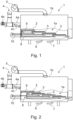
- the burner 1 comprises an input pipe 6 and an output pipe 7 for the circulation of the cooling liquid of the liquid-cooled grate plates 2.
- the circulation piping of the cooling liquid e.g. water
- the input pipe 6 and output pipe 7 for cooling liquid are preferably connected to the liquid cooling system of the burner 1, which system is not presented in the drawings for the sake of clarity.
- the grate plates 2 and 3 are placed in the grate 1a row by row in such a way that closest to the fuel input end is the topmost row of grate plates situated side by side, which grate plates are preferably fixed, i.e. stationary, grate plates 2.
- grate plates are preferably fixed, i.e. stationary, grate plates 2.
- the next row of grate plates situated side by side which are now preferably movable grate plates 3, which are not provided with liquid cooling ducts or a liquid cooling space, so that there is no circulation of the cooling liquid inside them or in connection with them.
- the third row, below and overlapping the second row is again a row of liquid-cooled fixed grate plates 2, and so on, always with the next row below and overlapping the previous row and farther away from it going towards the second end of the burner 1.
- the solid fuel of the burner 1 is fed via the fuel input aperture 4 to a screw conveyor 4a, which conveys the solid fuel to the combustion chamber of the burner 1 for burning, in which combustion chamber the fuel is first guided to the topmost stationary grate plates 2 of the burner 1.
- the burnt solid fuel is transferred in the combustion chamber of the burner 1 preferably by means of the movable grate plates 3, which move between the stationary grate plates 2 in the direction of the stationary grate plates 2, i.e. towards the second end of the burner 1.
- Figs. 3-5 present one stationary grate plate 2 of a burner 1 according to the invention.
- Fig. 3 presents the frame part 2a of a grate plate 2 with its cooling liquid ducts 9
- Fig. 4 presents the cover plate 11 to be placed onto the ducts 9
- Fig. 5 the grate plate 2 assembled as a package with the cover 11 attached to the frame part 2a.
- Fig. 3 shows one stationary grate plate 2 of the burner 1 according to the invention and its cooling duct 9, which is arranged to run along a tortuous path inside the frame part 2 and to cover as large a surface area as possible of the second planar surface of the grate plate 2, preferably of the top surface.
- the shape of the route, including the bends, of the duct 9 is implemented with mutually parallel, preferably straight, support elements 2b, which have a plurality of holes 2c extending through the entire grate plate 2 in the thickness direction for the passage of air and ash.
- cooling ducts of grate plates can be only in stationary grate plates or only in some of them, or only in movable grate plates or only in some of them, or in both stationary and movable grate plates or only in some of them.
- the moving mechanism of the movable grate plates can also be different in structure than the moving mechanism described above.
Landscapes
- Engineering & Computer Science (AREA)
- Chemical & Material Sciences (AREA)
- Combustion & Propulsion (AREA)
- Mechanical Engineering (AREA)
- General Engineering & Computer Science (AREA)
- Incineration Of Waste (AREA)
- Furnace Details (AREA)
Claims (9)
- Flüssigkeitsgekühlter Rost (1a) für einen Festbrennstoffbrenner (1), wobei der Rost eine Eintrittsöffnung (4) für Brennstoff, ein Gebläse (5) und ein Zirkulationssystem für das Kühlfluid aufweist, und welcher Rost (1a) eine oder mehrere durch eine stationäre Rostplatte (2) gebildete stationäre Rostebenen und eine oder mehrere durch eine bewegliche Rostplatte (3) gebildete bewegliche Rostebenen umfasst, welche Rostebenen überlappend übereinander angeordnet sind, wobei die stationäre Rostplatte (2) einen Kühlkanal (9) aufweist, welcher Kühlkanal (9) an seinem ersten Ende eine Eingangsöffnung (6a) und an seinem zweiten Ende eine Ausgangsöffnung (7a) aufweist, und jede flüssigkeitsgekühlte stationäre Rostplatte (2) dazu geeignet ist, die darunter und/oder darüber liegende bewegliche Rostplatte (3) zu kühlen, in der keine Flüssigkeitskühlung vorhanden ist, wobei die Form des Verlaufs, einschließlich der Krümmungen, des Kühlkanals (9) mit zueinander parallelen, vorzugsweise geraden Stützelementen (2b) ausgeführt ist, dadurch gekennzeichnet, dass jedes der Stützelemente (2b) eine Vielzahl von Löchern (2c) aufweist, die sich durch die gesamte Rostplatte (2) in Dickenrichtung für den Durchgang von Luft und Asche erstrecken.
- Rost nach Anspruch 1, dadurch gekennzeichnet, dass die Rostplatten (2, 3) in dem Rost (1a) reihenweise so angeordnet sind, dass die oberste Reihe stationärer, nebeneinander liegender Rostplatten (2) dem Brennstoffzufuhrende am nächsten ist, wobei die Rostplatten eine Flüssigkeitskühlung aufweisen.
- Rost nach Anspruch 1 oder 2, dadurch gekennzeichnet, dass unterhalb der obersten Rostreihe überlappend eine Reihe von nebeneinander angeordneten beweglichen Rostplatten (3) vorhanden ist, in denen keine Flüssigkeitskühlung stattfindet.
- Rost nach Anspruch 1, 2 oder 3, dadurch gekennzeichnet, dass unterhalb der sich überlappenden beweglichen Rostplatten (3) wiederum eine Reihe stationärer Rostplatten (2) nebeneinander angeordnet ist, die eine Flüssigkeitskühlung aufweisen, und somit die stationären flüssigkeitsgekühlten Rostplattenreihen und die beweglichen Rostplattenreihen, die keine Flüssigkeitskühlung enthalten, in gleicher Weise überlappend untereinander und abwechselnd zum zweiten Ende des Kessels (1b) hin angeordnet sind.
- Rost nach einem der vorhergehenden Ansprüche, dadurch gekennzeichnet, dass der Brenner (1) Zirkulationsleitungen für eine Kühlflüssigkeit, wie z.B. Wasser, umfasst, wobei die Leitungen mit jeder flüssigkeitsgekühlten stationären Rostplatte (2) derart verbunden sind, dass die Kühlflüssigkeit im Wesentlichen in allen stationären Rostplatten (2) zirkuliert.
- Rost nach einem der vorhergehenden Ansprüche, dadurch gekennzeichnet, dass der Kühlkanal (9) auf einer Seite der Rostplatte (2) mit einer Abdeckplatte (11) verschlossen ist.
- Gitterrost nach Anspruch 6, dadurch gekennzeichnet, dass der Kühlkanal (9) so angepasst ist, dass er entlang eines gewundenen Weges innerhalb des Rahmenteils der festen Rostplatte (2) verläuft und eine möglichst große Fläche der oberen Oberfläche der festen Rostplatte (2) abdeckt.
- Rost nach Anspruch 6 oder 7, dadurch gekennzeichnet, dass jedes zweite Stützelement (2b) an der Innenfläche der ersten Stirnwand des Rahmenteils (2a) der Rostplatte (2) befestigt ist und sich zur zweiten Stirnwand hin so erstreckt, dass das freie Ende des Stützelements (2b) etwa die Breite des Kanals (9) von der Innenfläche der zweiten Stirnwand entfernt ist, und dementsprechend ist jedes andere Stützelement (2b) an der Innenfläche der zweiten Endwand des Rahmenteils (2a) befestigt und erstreckt sich in Richtung der ersten Endwand, so dass das freie Ende des Stützelements (2b) ungefähr die Breite des Kanals (9) von der Innenfläche der ersten Endwand entfernt ist.
- Rost nach einem der vorhergehenden Ansprüche, dadurch gekennzeichnet, dass der Brenner (1) einen Bewegungsmechanismus (8) umfasst, der mit einem Antriebsmittel (10) versehen ist, um die beweglichen Rostplatten (3) zwischen den feststehenden Rostplatten (2) in Längsrichtung des Kessels (1b) hin und her zu bewegen.
Applications Claiming Priority (1)
| Application Number | Priority Date | Filing Date | Title |
|---|---|---|---|
| FI20215661A FI20215661A1 (fi) | 2021-06-07 | 2021-06-07 | Nestejäähdytteinen arina kiinteän polttoaineen polttimessa |
Publications (2)
| Publication Number | Publication Date |
|---|---|
| EP4102133A1 EP4102133A1 (de) | 2022-12-14 |
| EP4102133B1 true EP4102133B1 (de) | 2024-11-27 |
Family
ID=82786846
Family Applications (1)
| Application Number | Title | Priority Date | Filing Date |
|---|---|---|---|
| EP22176987.0A Active EP4102133B1 (de) | 2021-06-07 | 2022-06-02 | Flüssigkeitsgekühlter rost in einem festbrennstoffbrenner |
Country Status (2)
| Country | Link |
|---|---|
| EP (1) | EP4102133B1 (de) |
| FI (2) | FI20215661A1 (de) |
Family Cites Families (5)
| Publication number | Priority date | Publication date | Assignee | Title |
|---|---|---|---|---|
| WO1995018333A1 (de) * | 1993-12-24 | 1995-07-06 | Doikos Investments Limited | Schub-verbrennungsrost-modul zum verbrennen von kehricht in grossanlagen, sowie verfahren zu dessen betrieb |
| ATE210800T1 (de) | 1998-11-10 | 2001-12-15 | Doikos Investments Ltd | Wassergekühlter verbrennungsrost, sowie verfahren zum verbrennen von kehricht auf demselben |
| FR2868514B1 (fr) * | 2004-04-01 | 2006-06-16 | Vinci Environnement Sa | Grille d'incineration a gradins fixes refroidis a l'eau |
| CN106439868A (zh) * | 2016-08-17 | 2017-02-22 | 光大环保技术研究院(深圳)有限公司 | 一种水冷炉排片和焚烧炉 |
| ES2987363T3 (es) * | 2020-09-09 | 2024-11-14 | Kanadevia Inova Ag | Bloque de parrilla refrigerado por agua para una instalación de incineración |
-
2021
- 2021-06-07 FI FI20215661A patent/FI20215661A1/fi unknown
-
2022
- 2022-06-02 EP EP22176987.0A patent/EP4102133B1/de active Active
- 2022-06-02 FI FIEP22176987.0T patent/FI4102133T3/fi active
Also Published As
| Publication number | Publication date |
|---|---|
| FI4102133T3 (fi) | 2025-03-08 |
| FI20215661A1 (fi) | 2022-12-08 |
| EP4102133A1 (de) | 2022-12-14 |
Similar Documents
| Publication | Publication Date | Title |
|---|---|---|
| KR100494968B1 (ko) | 수냉식드러스트연소화격자 | |
| CN103154615A (zh) | 具有平行设置驱动装置的水冷式滑动燃烧炉箅 | |
| EP1639297B1 (de) | Rostblock für einen müllverbrennungsrost | |
| FI85420C (fi) | Anordning vid snedrost i foerbraenningsugns eldstad. | |
| EP4102133B1 (de) | Flüssigkeitsgekühlter rost in einem festbrennstoffbrenner | |
| CN114893778A (zh) | 一种炉排框架、炉排段和焚烧炉 | |
| KR102196355B1 (ko) | 고형연료 소각로 | |
| KR102319512B1 (ko) | 화격자를 구비한 소각로 | |
| EP2504626B1 (de) | Müllentsorgungsanlage mit beweglichem rahmen | |
| EP2430383B1 (de) | Modul zur verwendung mit einem system zum lateraltransport | |
| US8522697B2 (en) | Waste disposal plant with modular frame and guide assembly | |
| US6938563B2 (en) | Grate furnace | |
| US20030024449A1 (en) | Grate furnace | |
| CN115103980B (zh) | 炉条以及炉条装置 | |
| JP2000065332A (ja) | 焼却設備用の火格子 | |
| KR200499322Y1 (ko) | 소각로용 수냉식 화격자 | |
| US9038551B2 (en) | Waste disposal plant with modular frame and guide assembly | |
| RU2857427C1 (ru) | Ретортная горелка с водяным охлаждением | |
| DE926978C (de) | Gaserzeuger | |
| WO2011063912A1 (en) | A waste disposal plant with fire bar approaching system. | |
| EP4303492A1 (de) | Plattenförmiges rostelement für einen beweglichen rost eines ofens | |
| KR102786658B1 (ko) | 폐기물을 완전연소 시키기 위한 수냉식과 공랭식 하이브리드 화격자가 구비된 소각로 | |
| RU2231714C2 (ru) | Топка для сжигания твердого топлива в кипящем слое | |
| AT501344B1 (de) | Pelletkessel | |
| US667399A (en) | Furnace-grate. |
Legal Events
| Date | Code | Title | Description |
|---|---|---|---|
| PUAI | Public reference made under article 153(3) epc to a published international application that has entered the european phase |
Free format text: ORIGINAL CODE: 0009012 |
|
| STAA | Information on the status of an ep patent application or granted ep patent |
Free format text: STATUS: THE APPLICATION HAS BEEN PUBLISHED |
|
| AK | Designated contracting states |
Kind code of ref document: A1 Designated state(s): AL AT BE BG CH CY CZ DE DK EE ES FI FR GB GR HR HU IE IS IT LI LT LU LV MC MK MT NL NO PL PT RO RS SE SI SK SM TR |
|
| STAA | Information on the status of an ep patent application or granted ep patent |
Free format text: STATUS: REQUEST FOR EXAMINATION WAS MADE |
|
| 17P | Request for examination filed |
Effective date: 20230614 |
|
| RBV | Designated contracting states (corrected) |
Designated state(s): AL AT BE BG CH CY CZ DE DK EE ES FI FR GB GR HR HU IE IS IT LI LT LU LV MC MK MT NL NO PL PT RO RS SE SI SK SM TR |
|
| GRAP | Despatch of communication of intention to grant a patent |
Free format text: ORIGINAL CODE: EPIDOSNIGR1 |
|
| STAA | Information on the status of an ep patent application or granted ep patent |
Free format text: STATUS: GRANT OF PATENT IS INTENDED |
|
| INTG | Intention to grant announced |
Effective date: 20240624 |
|
| GRAS | Grant fee paid |
Free format text: ORIGINAL CODE: EPIDOSNIGR3 |
|
| GRAA | (expected) grant |
Free format text: ORIGINAL CODE: 0009210 |
|
| STAA | Information on the status of an ep patent application or granted ep patent |
Free format text: STATUS: THE PATENT HAS BEEN GRANTED |
|
| AK | Designated contracting states |
Kind code of ref document: B1 Designated state(s): AL AT BE BG CH CY CZ DE DK EE ES FI FR GB GR HR HU IE IS IT LI LT LU LV MC MK MT NL NO PL PT RO RS SE SI SK SM TR |
|
| REG | Reference to a national code |
Ref country code: GB Ref legal event code: FG4D |
|
| REG | Reference to a national code |
Ref country code: CH Ref legal event code: EP |
|
| REG | Reference to a national code |
Ref country code: IE Ref legal event code: FG4D |
|
| REG | Reference to a national code |
Ref country code: DE Ref legal event code: R096 Ref document number: 602022008084 Country of ref document: DE |
|
| REG | Reference to a national code |
Ref country code: FI Ref legal event code: FGE |
|
| REG | Reference to a national code |
Ref country code: LT Ref legal event code: MG9D |
|
| REG | Reference to a national code |
Ref country code: NL Ref legal event code: MP Effective date: 20241127 |
|
| PG25 | Lapsed in a contracting state [announced via postgrant information from national office to epo] |
Ref country code: HR Free format text: LAPSE BECAUSE OF FAILURE TO SUBMIT A TRANSLATION OF THE DESCRIPTION OR TO PAY THE FEE WITHIN THE PRESCRIBED TIME-LIMIT Effective date: 20241127 Ref country code: IS Free format text: LAPSE BECAUSE OF FAILURE TO SUBMIT A TRANSLATION OF THE DESCRIPTION OR TO PAY THE FEE WITHIN THE PRESCRIBED TIME-LIMIT Effective date: 20250327 Ref country code: PT Free format text: LAPSE BECAUSE OF FAILURE TO SUBMIT A TRANSLATION OF THE DESCRIPTION OR TO PAY THE FEE WITHIN THE PRESCRIBED TIME-LIMIT Effective date: 20250327 |
|
| PG25 | Lapsed in a contracting state [announced via postgrant information from national office to epo] |
Ref country code: NL Free format text: LAPSE BECAUSE OF FAILURE TO SUBMIT A TRANSLATION OF THE DESCRIPTION OR TO PAY THE FEE WITHIN THE PRESCRIBED TIME-LIMIT Effective date: 20241127 |
|
| REG | Reference to a national code |
Ref country code: AT Ref legal event code: MK05 Ref document number: 1746026 Country of ref document: AT Kind code of ref document: T Effective date: 20241127 |
|
| PG25 | Lapsed in a contracting state [announced via postgrant information from national office to epo] |
Ref country code: BG Free format text: LAPSE BECAUSE OF FAILURE TO SUBMIT A TRANSLATION OF THE DESCRIPTION OR TO PAY THE FEE WITHIN THE PRESCRIBED TIME-LIMIT Effective date: 20241127 |
|
| PG25 | Lapsed in a contracting state [announced via postgrant information from national office to epo] |
Ref country code: ES Free format text: LAPSE BECAUSE OF FAILURE TO SUBMIT A TRANSLATION OF THE DESCRIPTION OR TO PAY THE FEE WITHIN THE PRESCRIBED TIME-LIMIT Effective date: 20241127 |
|
| PG25 | Lapsed in a contracting state [announced via postgrant information from national office to epo] |
Ref country code: NO Free format text: LAPSE BECAUSE OF FAILURE TO SUBMIT A TRANSLATION OF THE DESCRIPTION OR TO PAY THE FEE WITHIN THE PRESCRIBED TIME-LIMIT Effective date: 20250227 |
|
| PG25 | Lapsed in a contracting state [announced via postgrant information from national office to epo] |
Ref country code: GR Free format text: LAPSE BECAUSE OF FAILURE TO SUBMIT A TRANSLATION OF THE DESCRIPTION OR TO PAY THE FEE WITHIN THE PRESCRIBED TIME-LIMIT Effective date: 20250228 Ref country code: LV Free format text: LAPSE BECAUSE OF FAILURE TO SUBMIT A TRANSLATION OF THE DESCRIPTION OR TO PAY THE FEE WITHIN THE PRESCRIBED TIME-LIMIT Effective date: 20241127 Ref country code: AT Free format text: LAPSE BECAUSE OF FAILURE TO SUBMIT A TRANSLATION OF THE DESCRIPTION OR TO PAY THE FEE WITHIN THE PRESCRIBED TIME-LIMIT Effective date: 20241127 |
|
| PG25 | Lapsed in a contracting state [announced via postgrant information from national office to epo] |
Ref country code: PL Free format text: LAPSE BECAUSE OF FAILURE TO SUBMIT A TRANSLATION OF THE DESCRIPTION OR TO PAY THE FEE WITHIN THE PRESCRIBED TIME-LIMIT Effective date: 20241127 |
|
| PG25 | Lapsed in a contracting state [announced via postgrant information from national office to epo] |
Ref country code: RS Free format text: LAPSE BECAUSE OF FAILURE TO SUBMIT A TRANSLATION OF THE DESCRIPTION OR TO PAY THE FEE WITHIN THE PRESCRIBED TIME-LIMIT Effective date: 20250227 |
|
| PG25 | Lapsed in a contracting state [announced via postgrant information from national office to epo] |
Ref country code: SM Free format text: LAPSE BECAUSE OF FAILURE TO SUBMIT A TRANSLATION OF THE DESCRIPTION OR TO PAY THE FEE WITHIN THE PRESCRIBED TIME-LIMIT Effective date: 20241127 |
|
| PG25 | Lapsed in a contracting state [announced via postgrant information from national office to epo] |
Ref country code: DK Free format text: LAPSE BECAUSE OF FAILURE TO SUBMIT A TRANSLATION OF THE DESCRIPTION OR TO PAY THE FEE WITHIN THE PRESCRIBED TIME-LIMIT Effective date: 20241127 |
|
| PG25 | Lapsed in a contracting state [announced via postgrant information from national office to epo] |
Ref country code: EE Free format text: LAPSE BECAUSE OF FAILURE TO SUBMIT A TRANSLATION OF THE DESCRIPTION OR TO PAY THE FEE WITHIN THE PRESCRIBED TIME-LIMIT Effective date: 20241127 |
|
| PG25 | Lapsed in a contracting state [announced via postgrant information from national office to epo] |
Ref country code: RO Free format text: LAPSE BECAUSE OF FAILURE TO SUBMIT A TRANSLATION OF THE DESCRIPTION OR TO PAY THE FEE WITHIN THE PRESCRIBED TIME-LIMIT Effective date: 20241127 |
|
| PG25 | Lapsed in a contracting state [announced via postgrant information from national office to epo] |
Ref country code: SK Free format text: LAPSE BECAUSE OF FAILURE TO SUBMIT A TRANSLATION OF THE DESCRIPTION OR TO PAY THE FEE WITHIN THE PRESCRIBED TIME-LIMIT Effective date: 20241127 |
|
| PG25 | Lapsed in a contracting state [announced via postgrant information from national office to epo] |
Ref country code: CZ Free format text: LAPSE BECAUSE OF FAILURE TO SUBMIT A TRANSLATION OF THE DESCRIPTION OR TO PAY THE FEE WITHIN THE PRESCRIBED TIME-LIMIT Effective date: 20241127 |
|
| PG25 | Lapsed in a contracting state [announced via postgrant information from national office to epo] |
Ref country code: IT Free format text: LAPSE BECAUSE OF FAILURE TO SUBMIT A TRANSLATION OF THE DESCRIPTION OR TO PAY THE FEE WITHIN THE PRESCRIBED TIME-LIMIT Effective date: 20241127 |
|
| REG | Reference to a national code |
Ref country code: DE Ref legal event code: R097 Ref document number: 602022008084 Country of ref document: DE |
|
| PG25 | Lapsed in a contracting state [announced via postgrant information from national office to epo] |
Ref country code: SE Free format text: LAPSE BECAUSE OF FAILURE TO SUBMIT A TRANSLATION OF THE DESCRIPTION OR TO PAY THE FEE WITHIN THE PRESCRIBED TIME-LIMIT Effective date: 20241127 |
|
| PLBE | No opposition filed within time limit |
Free format text: ORIGINAL CODE: 0009261 |
|
| STAA | Information on the status of an ep patent application or granted ep patent |
Free format text: STATUS: NO OPPOSITION FILED WITHIN TIME LIMIT |
|
| REG | Reference to a national code |
Ref country code: CH Ref legal event code: L10 Free format text: ST27 STATUS EVENT CODE: U-0-0-L10-L00 (AS PROVIDED BY THE NATIONAL OFFICE) Effective date: 20251008 |
|
| 26N | No opposition filed |
Effective date: 20250828 |
|
| REG | Reference to a national code |
Ref country code: DE Ref legal event code: R119 Ref document number: 602022008084 Country of ref document: DE |
|
| PGFP | Annual fee paid to national office [announced via postgrant information from national office to epo] |
Ref country code: FI Payment date: 20251230 Year of fee payment: 4 |
|
| REG | Reference to a national code |
Ref country code: CH Ref legal event code: H13 Free format text: ST27 STATUS EVENT CODE: U-0-0-H10-H13 (AS PROVIDED BY THE NATIONAL OFFICE) Effective date: 20260127 |
|
| PG25 | Lapsed in a contracting state [announced via postgrant information from national office to epo] |
Ref country code: MC Free format text: LAPSE BECAUSE OF FAILURE TO SUBMIT A TRANSLATION OF THE DESCRIPTION OR TO PAY THE FEE WITHIN THE PRESCRIBED TIME-LIMIT Effective date: 20241127 |
|
| PG25 | Lapsed in a contracting state [announced via postgrant information from national office to epo] |
Ref country code: LU Free format text: LAPSE BECAUSE OF NON-PAYMENT OF DUE FEES Effective date: 20250602 |
|
| REG | Reference to a national code |
Ref country code: BE Ref legal event code: MM Effective date: 20250630 |