EP4102109A1 - Piece mecanique pour une turbomachine d'aeronef et turbomachine correspondante - Google Patents
Piece mecanique pour une turbomachine d'aeronef et turbomachine correspondante Download PDFInfo
- Publication number
- EP4102109A1 EP4102109A1 EP22177281.7A EP22177281A EP4102109A1 EP 4102109 A1 EP4102109 A1 EP 4102109A1 EP 22177281 A EP22177281 A EP 22177281A EP 4102109 A1 EP4102109 A1 EP 4102109A1
- Authority
- EP
- European Patent Office
- Prior art keywords
- mechanical part
- mechanical
- oil
- hydrophobic
- crown
- Prior art date
- Legal status (The legal status is an assumption and is not a legal conclusion. Google has not performed a legal analysis and makes no representation as to the accuracy of the status listed.)
- Pending
Links
Images



Classifications
-
- F—MECHANICAL ENGINEERING; LIGHTING; HEATING; WEAPONS; BLASTING
- F16—ENGINEERING ELEMENTS AND UNITS; GENERAL MEASURES FOR PRODUCING AND MAINTAINING EFFECTIVE FUNCTIONING OF MACHINES OR INSTALLATIONS; THERMAL INSULATION IN GENERAL
- F16H—GEARING
- F16H57/00—General details of gearing
- F16H57/04—Features relating to lubrication or cooling or heating
- F16H57/042—Guidance of lubricant
- F16H57/0421—Guidance of lubricant on or within the casing, e.g. shields or baffles for collecting lubricant, tubes, pipes, grooves, channels or the like
- F16H57/0423—Lubricant guiding means mounted or supported on the casing, e.g. shields or baffles for collecting lubricant, tubes or pipes
-
- F—MECHANICAL ENGINEERING; LIGHTING; HEATING; WEAPONS; BLASTING
- F02—COMBUSTION ENGINES; HOT-GAS OR COMBUSTION-PRODUCT ENGINE PLANTS
- F02C—GAS-TURBINE PLANTS; AIR INTAKES FOR JET-PROPULSION PLANTS; CONTROLLING FUEL SUPPLY IN AIR-BREATHING JET-PROPULSION PLANTS
- F02C7/00—Features, components parts, details or accessories, not provided for in, or of interest apart form groups F02C1/00 - F02C6/00; Air intakes for jet-propulsion plants
- F02C7/06—Arrangements of bearings; Lubricating
-
- F—MECHANICAL ENGINEERING; LIGHTING; HEATING; WEAPONS; BLASTING
- F02—COMBUSTION ENGINES; HOT-GAS OR COMBUSTION-PRODUCT ENGINE PLANTS
- F02C—GAS-TURBINE PLANTS; AIR INTAKES FOR JET-PROPULSION PLANTS; CONTROLLING FUEL SUPPLY IN AIR-BREATHING JET-PROPULSION PLANTS
- F02C7/00—Features, components parts, details or accessories, not provided for in, or of interest apart form groups F02C1/00 - F02C6/00; Air intakes for jet-propulsion plants
- F02C7/36—Power transmission arrangements between the different shafts of the gas turbine plant, or between the gas-turbine plant and the power user
-
- F—MECHANICAL ENGINEERING; LIGHTING; HEATING; WEAPONS; BLASTING
- F16—ENGINEERING ELEMENTS AND UNITS; GENERAL MEASURES FOR PRODUCING AND MAINTAINING EFFECTIVE FUNCTIONING OF MACHINES OR INSTALLATIONS; THERMAL INSULATION IN GENERAL
- F16H—GEARING
- F16H57/00—General details of gearing
- F16H57/02—Gearboxes; Mounting gearing therein
- F16H57/023—Mounting or installation of gears or shafts in the gearboxes, e.g. methods or means for assembly
-
- F—MECHANICAL ENGINEERING; LIGHTING; HEATING; WEAPONS; BLASTING
- F16—ENGINEERING ELEMENTS AND UNITS; GENERAL MEASURES FOR PRODUCING AND MAINTAINING EFFECTIVE FUNCTIONING OF MACHINES OR INSTALLATIONS; THERMAL INSULATION IN GENERAL
- F16H—GEARING
- F16H57/00—General details of gearing
- F16H57/04—Features relating to lubrication or cooling or heating
- F16H57/042—Guidance of lubricant
- F16H57/043—Guidance of lubricant within rotary parts, e.g. axial channels or radial openings in shafts
-
- F—MECHANICAL ENGINEERING; LIGHTING; HEATING; WEAPONS; BLASTING
- F16—ENGINEERING ELEMENTS AND UNITS; GENERAL MEASURES FOR PRODUCING AND MAINTAINING EFFECTIVE FUNCTIONING OF MACHINES OR INSTALLATIONS; THERMAL INSULATION IN GENERAL
- F16H—GEARING
- F16H57/00—General details of gearing
- F16H57/04—Features relating to lubrication or cooling or heating
- F16H57/045—Lubricant storage reservoirs, e.g. reservoirs in addition to a gear sump for collecting lubricant in the upper part of a gear case
-
- F—MECHANICAL ENGINEERING; LIGHTING; HEATING; WEAPONS; BLASTING
- F16—ENGINEERING ELEMENTS AND UNITS; GENERAL MEASURES FOR PRODUCING AND MAINTAINING EFFECTIVE FUNCTIONING OF MACHINES OR INSTALLATIONS; THERMAL INSULATION IN GENERAL
- F16H—GEARING
- F16H57/00—General details of gearing
- F16H57/04—Features relating to lubrication or cooling or heating
- F16H57/0456—Lubrication by injection; Injection nozzles or tubes therefor
-
- F—MECHANICAL ENGINEERING; LIGHTING; HEATING; WEAPONS; BLASTING
- F16—ENGINEERING ELEMENTS AND UNITS; GENERAL MEASURES FOR PRODUCING AND MAINTAINING EFFECTIVE FUNCTIONING OF MACHINES OR INSTALLATIONS; THERMAL INSULATION IN GENERAL
- F16H—GEARING
- F16H57/00—General details of gearing
- F16H57/04—Features relating to lubrication or cooling or heating
- F16H57/0467—Elements of gearings to be lubricated, cooled or heated
- F16H57/0479—Gears or bearings on planet carriers
-
- F—MECHANICAL ENGINEERING; LIGHTING; HEATING; WEAPONS; BLASTING
- F16—ENGINEERING ELEMENTS AND UNITS; GENERAL MEASURES FOR PRODUCING AND MAINTAINING EFFECTIVE FUNCTIONING OF MACHINES OR INSTALLATIONS; THERMAL INSULATION IN GENERAL
- F16H—GEARING
- F16H57/00—General details of gearing
- F16H57/08—General details of gearing of gearings with members having orbital motion
-
- F—MECHANICAL ENGINEERING; LIGHTING; HEATING; WEAPONS; BLASTING
- F01—MACHINES OR ENGINES IN GENERAL; ENGINE PLANTS IN GENERAL; STEAM ENGINES
- F01D—NON-POSITIVE DISPLACEMENT MACHINES OR ENGINES, e.g. STEAM TURBINES
- F01D25/00—Component parts, details, or accessories, not provided for in, or of interest apart from, other groups
- F01D25/18—Lubricating arrangements
-
- F—MECHANICAL ENGINEERING; LIGHTING; HEATING; WEAPONS; BLASTING
- F05—INDEXING SCHEMES RELATING TO ENGINES OR PUMPS IN VARIOUS SUBCLASSES OF CLASSES F01-F04
- F05D—INDEXING SCHEME FOR ASPECTS RELATING TO NON-POSITIVE-DISPLACEMENT MACHINES OR ENGINES, GAS-TURBINES OR JET-PROPULSION PLANTS
- F05D2240/00—Components
- F05D2240/10—Stators
- F05D2240/12—Fluid guiding means, e.g. vanes
-
- F—MECHANICAL ENGINEERING; LIGHTING; HEATING; WEAPONS; BLASTING
- F05—INDEXING SCHEMES RELATING TO ENGINES OR PUMPS IN VARIOUS SUBCLASSES OF CLASSES F01-F04
- F05D—INDEXING SCHEME FOR ASPECTS RELATING TO NON-POSITIVE-DISPLACEMENT MACHINES OR ENGINES, GAS-TURBINES OR JET-PROPULSION PLANTS
- F05D2260/00—Function
- F05D2260/40—Transmission of power
- F05D2260/403—Transmission of power through the shape of the drive components
- F05D2260/4031—Transmission of power through the shape of the drive components as in toothed gearing
- F05D2260/40311—Transmission of power through the shape of the drive components as in toothed gearing of the epicyclical, planetary or differential type
-
- F—MECHANICAL ENGINEERING; LIGHTING; HEATING; WEAPONS; BLASTING
- F05—INDEXING SCHEMES RELATING TO ENGINES OR PUMPS IN VARIOUS SUBCLASSES OF CLASSES F01-F04
- F05D—INDEXING SCHEME FOR ASPECTS RELATING TO NON-POSITIVE-DISPLACEMENT MACHINES OR ENGINES, GAS-TURBINES OR JET-PROPULSION PLANTS
- F05D2260/00—Function
- F05D2260/98—Lubrication
-
- F—MECHANICAL ENGINEERING; LIGHTING; HEATING; WEAPONS; BLASTING
- F05—INDEXING SCHEMES RELATING TO ENGINES OR PUMPS IN VARIOUS SUBCLASSES OF CLASSES F01-F04
- F05D—INDEXING SCHEME FOR ASPECTS RELATING TO NON-POSITIVE-DISPLACEMENT MACHINES OR ENGINES, GAS-TURBINES OR JET-PROPULSION PLANTS
- F05D2300/00—Materials; Properties thereof
- F05D2300/50—Intrinsic material properties or characteristics
- F05D2300/512—Hydrophobic, i.e. being or having non-wettable properties
-
- F—MECHANICAL ENGINEERING; LIGHTING; HEATING; WEAPONS; BLASTING
- F05—INDEXING SCHEMES RELATING TO ENGINES OR PUMPS IN VARIOUS SUBCLASSES OF CLASSES F01-F04
- F05D—INDEXING SCHEME FOR ASPECTS RELATING TO NON-POSITIVE-DISPLACEMENT MACHINES OR ENGINES, GAS-TURBINES OR JET-PROPULSION PLANTS
- F05D2300/00—Materials; Properties thereof
- F05D2300/60—Properties or characteristics given to material by treatment or manufacturing
- F05D2300/611—Coating
-
- F—MECHANICAL ENGINEERING; LIGHTING; HEATING; WEAPONS; BLASTING
- F16—ENGINEERING ELEMENTS AND UNITS; GENERAL MEASURES FOR PRODUCING AND MAINTAINING EFFECTIVE FUNCTIONING OF MACHINES OR INSTALLATIONS; THERMAL INSULATION IN GENERAL
- F16H—GEARING
- F16H57/00—General details of gearing
- F16H57/04—Features relating to lubrication or cooling or heating
- F16H57/048—Type of gearings to be lubricated, cooled or heated
- F16H57/0482—Gearings with gears having orbital motion
- F16H57/0486—Gearings with gears having orbital motion with fixed gear ratio
-
- Y—GENERAL TAGGING OF NEW TECHNOLOGICAL DEVELOPMENTS; GENERAL TAGGING OF CROSS-SECTIONAL TECHNOLOGIES SPANNING OVER SEVERAL SECTIONS OF THE IPC; TECHNICAL SUBJECTS COVERED BY FORMER USPC CROSS-REFERENCE ART COLLECTIONS [XRACs] AND DIGESTS
- Y02—TECHNOLOGIES OR APPLICATIONS FOR MITIGATION OR ADAPTATION AGAINST CLIMATE CHANGE
- Y02T—CLIMATE CHANGE MITIGATION TECHNOLOGIES RELATED TO TRANSPORTATION
- Y02T50/00—Aeronautics or air transport
- Y02T50/60—Efficient propulsion technologies, e.g. for aircraft
Definitions
- the present invention relates to the general field of turbomachines and in particular aircraft turbomachines. It relates in particular to a turbomachine part intended to ensure a flow of oil in operation.
- Prior art includes documents JP-A-2011 112145 , JP-A-2011 185322 , US-A1-2020/309032 .
- An aircraft turbine engine notably consumes oil to operate. This oil is for example necessary to ensure the lubrication of mechanical parts, such as bearings or gears, and can also be used to cool these parts.
- Certain mechanical parts of an aircraft turbine engine have profiled surfaces to ensure oil flow during operation. This is for example the case of gutters for recovering lubricating oil from a mechanical reducer, in particular with a gear train.
- a mechanical reducer is to modify the speed and torque ratio between an input axis and an output axis of a mechanical system.
- the mechanical reducer comprises a sun gear, a crown and satellites which are meshed between the sun gear and the crown.
- the satellites are held by a frame called the planet carrier.
- the reduction gears are of the planetary gear or planetary gear type.
- differential or “compound” architectures there are so-called differential or “compound” architectures.
- a planetary gear reducer the planet carrier is fixed and the crown, mobile, constitutes the output shaft of the device which rotates in the opposite direction to the sun.
- the crown In a planetary gear reducer, the crown is fixed and the planet carrier constitutes the output shaft of the device which rotates in the same direction as the solar.
- no element is fixed in rotation. The crown rotates in the opposite direction to the sun and the planet carrier.
- reducers being composed of several wheels and/or pinions which mesh with each other, their lubrication is an essential aspect for the proper functioning of the reducer and of the turbomachine. Indeed, when the reducer is not sufficiently lubricated, the friction between the teeth of the wheels and/or pinions or at the level of the bearings causes their premature wear and thus a reduction in the efficiency of the reducer.
- the gearbox gear train generates high thermal power which causes the oil to heat up during operation; the oil absorbs heat energy generated by the gearbox. The temperature of the oil has an impact on its viscosity and on its lubricating efficiency. It is therefore important to evacuate the hot oil after the lubrication of the reducer, in order to recycle it.
- Recycling involves cooling, filtering and deaeration of the oil before being reinjected into the lubrication system. Recycling also makes it possible to avoid the increase in losses by ventilation of the reducer, the increase in the temperature of the internal organs of the reducer, an excessive air content in the oil, etc.
- an annular gutter arranged around the outer crown of the reducer has been proposed.
- the gutter typically has a U-shaped section.
- the bottom and the side walls of the gutter carry a surface which is oriented towards the periphery of the crown and which is intended to receive the oil splashes by centrifugation.
- the oil flows along this surface towards an outlet located in the lower part of the gutter. Examples of gutters are described in the patent application FR-A1-3081513 .
- the object of the invention is to avoid the aforementioned drawbacks.
- the object of the invention is to provide a simple, effective and economical solution making it possible to facilitate the flow of a fluid such as oil over an aircraft turbomachine part.
- a mechanical part for an aircraft turbomachine the mechanical part being made of metal and comprising at least one profiled surface configured to ensure oil flow in operation, said surface comprising a more hydrophobic coating and / or lipophobic than said surface or a surface texturing making said surface more hydrophobic and/or lipophobic, the part being an annular lubricating oil recovery gutter, in particular for a mechanical reducer.
- the surface coating or texturing makes it possible to render the oil flow surface hydrophobic and/or lipophobic. This makes it possible to reduce the spreading coefficient of the oil on the surface and therefore to promote the formation of drops for example rather than the spreading of the oil on the surface which then forms a film. This makes it possible to facilitate the flow of the oil on the surface which does not “attach” to the surface and therefore to accelerate this flow.
- the acceleration of the oil on the surface makes it possible to limit the impact of the ventilation air on this oil. It can also make it possible to accelerate the evacuation of oil and its recycling and thus make it possible to reduce the quantity of oil consumed in operation of the turbomachine.
- the invention also relates to a mechanical reduction gear for an aircraft turbomachine, the mechanical reduction gear having a planetary gear train and comprising a sun gear, a crown extending around the sun gear, satellites meshed with the sun gear and the crown, and at least one mechanical part, having any one of the preceding characteristics, arranged radially around the crown so that the surface extends around the crown.
- the invention also relates to a turbomachine comprising at least one mechanical part of the turbomachine as mentioned above or a mechanical reduction gear as mentioned above.
- the invention further relates to an aircraft comprising at least one turbine engine as mentioned above.
- the figure 1 shows a turbomachine which is intended to be mounted on an aircraft.
- the turbine engine illustrated is a dual-flow turbine engine, but the invention is not limited to this turbine engine.
- the turbomachine may be a turboprop engine and comprise a single propeller or a pair of counter-rotating propellers rotating around a longitudinal axis and designated by the expression “open rotor” in English for unducted propeller(s).
- the turbine engine can also be a turbine engine.
- a dual-flow turbomachine 1, of longitudinal axis X comprises, upstream to downstream and in the direction of flow of the gas flows, a compressor section, a combustion chamber 1c, and a turbine section .
- the compressor section may include a low pressure compressor 1a and a high pressure compressor 1b.
- the turbine section may include a low pressure turbine 1e and a high pressure turbine 1d.
- the compressors, the combustion chamber and the turbines form a gas generator.
- the high pressure compressor 1b and the high pressure turbine 1d are connected by a high pressure shaft 2 and form with it a high pressure body (HP).
- the low pressure compressor 1a and the low pressure turbine 1e are connected by a low pressure shaft 3 and form with it a low pressure body (LP).
- an exhaust nozzle 1h Downstream of the low pressure turbine 1e is arranged an exhaust nozzle 1h allowing the evacuation of the gases from the combustion chamber 1c to the outside.
- a fan 4 Upstream of the low pressure compressor 1a is mounted a fan 4.
- the fan 4 is driven by a fan shaft 5 which is driven by the LP shaft 3 by means of a mechanical reduction gear 6.
- the fan 4 comprises a plurality of fan blades 7 which extend radially outward from a fan disc.
- the fan blades 7 are delimited radially by a casing 8 of the fan. The latter carries a basket attached to the aircraft.
- the reducer 6 is made up of a gear train and is known by the English acronym RGB for “Reduction Gear Box”.
- the reducer 6 is generally of the planetary or planetary type.
- the reducer comprises, as illustrated schematically in the picture 2 , a solar 10 (or internal planetary), satellites 11, a planet carrier 12 and a crown 13 (or external planetary).
- the solar 10, the crown 13 and the planet carrier 12 are sun gears because their axes of revolution coincide with the longitudinal axis X of the turbomachine.
- the satellites each have a different axis of revolution and are evenly distributed over the same operating diameter around the axis of the planetary gears. These axes are parallel to the longitudinal axis X.
- the reducer 6 here has a planetary gear train.
- the input of the reducer is coupled to the BP shaft 3 while the output of the reducer is coupled to the fan shaft.
- the crown 13 is mobile in rotation and the planet carrier 12 is fixed in rotation.
- a fixed structure 14 comprises schematically, here, an upstream part 14a and a downstream part 14b, which composes the motor casing or stator.
- the fixed structure is arranged so as to form an enclosure E surrounding the reducer 6.
- This enclosure E is here closed upstream by seals at an upstream bearing allowing passage of the fan shaft 5, and downstream by joints at the level of the crossing of the LP shaft 3.
- the upstream bearing makes it possible to carry and guide in rotation the fan shaft 5 in order to support the radial and axial loads which the latter undergoes.
- This upstream bearing is mounted in the enclosure E. Two upstream bearings can be provided to guide the fan shaft 5 in rotation as illustrated in the picture 2 .
- the figure 2 and 3 show the reducer 6 which can take the form of different architectures depending on whether certain parts are fixed or rotating.
- the reducer 6 is connected to the BP shaft 3, for example via internal splines 15.
- the BP shaft 3 drives the sun.
- the sun gear 10 whose axis of rotation coincides with that of the turbomachine X, drives the satellites 11, which are evenly distributed over the same diameter around the axis of rotation X. This diameter is equal to twice the operating center distance between the solar 10 and the satellites 11.
- the number of satellites 11 is generally defined between three and seven for this type of application.
- the set of satellites 11 is held by a frame which is the planet carrier 12.
- All of the satellites 11 is held by the planet carrier 10 which is fixed to the motor casing or stator 14.
- Each satellite drives the ring gear 13 which is attached to the fan shaft 4.
- a ring gear carrier 16 is provided to connect the fan shaft fan 10 to crown 13.
- Satellites 11 are mounted free to rotate by means of bearings, for example of the bearing or hydrostatic bearing type.
- Each bearing is mounted on one of the axes of the planet carrier and all the axes are positioned with respect to each other using one or more structural frames of the planet carrier.
- the crown 13 is provided with internal toothing which meshes with the toothing of the satellites.
- crown 13 is formed in two parts (ie two half-crowns).
- a downstream half-ring 17 is made up of a rim 17a and a fixing half-flange 17b.
- Flange 17b extends radially outward.
- An upstream half-ring 18 is made up of a rim 18a and a fixing half-flange 18b.
- Flange 18b extends radially outward.
- the rim 17a comprises a portion of upstream toothing in the form of an upstream helix of the gear toothing. This upstream helix meshes with that of the satellite 11 which meshes with that of the sun gear 10.
- the rim 18a as for the latter comprises a portion of downstream toothing also in the form of a downstream helix of the gear toothing.
- This downstream propeller meshes with that of the satellite 11 which meshes with that of the solar 10.
- Such a configuration makes it possible to manufacture the crown even more easily and to facilitate the recovery of the oil. If the helix widths vary between the solar 10, the satellites 11 and the crown 13 because of the toothing overlaps, they are all centered on a median plane for the upstream helices and on another median plane for the downstream helices.
- the fixing half-flange 17b of the downstream half-ring and the fixing half-flange 18b of the upstream half-ring form the fixing flange 19 of the crown.
- the crown 13 is fixed to the crown holder by assembling the fixing flange 19 of the crown and a fixing flange of the crown holder. This fixing is carried out using fixing elements 20 such as screws, bolts and/or nuts.
- the oil arrives in the reducer 6 from the stator part 14 via a distributor (not shown) by various means which are specific to one or more types of architecture.
- the distributor is separated into two parts and in general each repeated by the same number of satellites.
- the distributor includes injectors 21a (cf. picture 3 ) which have the function of lubricating the teeth of the wheels and/or pinions of the reducer and the arms which have the function of lubricating the bearings of the reducer.
- the oil is brought to the injectors 21a to emerge from the ends in order to lubricate with so-called cold oil (HF) the teeth of the satellites 11, of the sun gear 10 and also of the ring gear 13.
- HF cold oil
- the oil is also brought to the arm and circulates via the supply port of the bearing.
- the oil then circulates through the shaft in one or more buffer zones and then exits through the orifices in order to lubricate the bearings of the satellites.
- the so-called hot oil HC for lubricating the teeth is projected radially outwards with respect to the axes Y of the satellites.
- the hot oil is also projected and ejected by centrifugal effect from the crown 13.
- the oil is in particular ejected radially outwards at the level of the fastening flange 19 via oil ejection means.
- the ejection means here comprise one or more channels which are regularly formed between the two half-rings and over the entire circumference of the ring 13.
- first channels 22 extend substantially along the radial axis Z.
- Each first channel 22 extends radially between an inlet 23 defined in an internal surface of the crown (and which comprises the toothing) and an outlet orifice 24 defined on the periphery of the fixing flange 19.
- the oil circulates from the inside the crown 13 towards the outside of the latter via the channel or channels 22.
- Second channels can also make it possible to evacuate the oil circulating on the outer periphery of the crown towards the first channels 22.
- the turbomachine is also equipped with an oil recovery device which is provided to quickly recover and evacuate the oil ejected by centrifugal effect from the reducer 6 and also from the enclosure E.
- the recovery device comprises a gutter 30 of oil recovery, annular, which is intended to recover the oil ejected from the reducer 6.
- the gutter 30, centered on the longitudinal axis X, is arranged around the crown 13.
- the gutter 30 is fixed to a fixed structure of the turbomachine (stator).
- the gutter 30 is fixed to the enclosure E enveloping the reducer.
- the gutter 30 has an axial section in the general shape of a U.
- the gutter 30 more specifically comprises a bottom wall 31 from which extend a first side wall 32 and a second side wall 33.
- the bottom wall 31 and the side walls 32, 33 are annular and centered on the longitudinal axis X.
- the side walls 32, 33 extend substantially radially (perpendicular to the longitudinal axis X).
- the bottom wall 31 is arranged radially outside the crown 13 and is oriented facing the oil ejection means.
- the side walls 32, 33 (called first and second walls) are arranged on either side of the fixing flange 19 along the longitudinal axis.
- the gutter 30 comprises a profiled surface 34, here internal, which faces the reducer 6 and the crown 13.
- Each side wall 32, 33 comprises a peripheral edge 35 delimiting an internal diameter of the gutter which is smaller than the external diameter of the crown 13 defined by the periphery of the fixing flange 19.
- the axis of the fixing members 20 of the fixing flange 19 delimits a diameter which is greater than the internal diameter of the peripheral edges 35.
- the bottom wall 31 and the side walls 32, 33 are arranged at a predetermined distance from the fixing flange 19, in particular its periphery and from the fixing members 19. These predetermined distances take into account the axial displacements of the crown during operation of the reducer, manufacturing tolerances and thermal expansion of the parts.
- the gutter 30 is formed of two parts in order to facilitate the assembly and the disassembly of the latter in the turbomachine.
- the gutter can be formed from a single piece (made from the material).
- the gutter 30 comprises a first part 30a and a second part 30b.
- the first part 30a comprises a first leg 36, the first side wall 32 and a bottom wall portion connecting the first leg 36 and the first side wall 32.
- the second part 30b comprises a second leg 37, the second side wall 33 and a bottom wall portion connecting the second tab 37 and the second side wall 33.
- the first and second tabs 36, 37 extend radially outwards.
- the first and second legs 36, 37 each comprise a support surface defined in a plane, and these planes are parallel.
- the first part and the second part are secured together at the first and second legs.
- Fixing members 38 make it possible to fix the tabs 36, 37 together.
- the fasteners 38 include screws, nuts, bolts or any other suitable device.
- the first tab 35 comprises an annular recess 36a intended to receive part of the second tab 37.
- the internal surface of the portions of the bottom walls and of the side walls have surface continuity and are flush.
- the first lug 36 which has a length greater than the second lug 37, allows the gutter 30 to be fixed to the fixed structure of the turbomachine.
- the gutter 30 comprises a single radial lug allowing attachment to the fixed structure of the turbomachine.
- the gutter 30 is made of a metallic material.
- the metallic material can be steel or titanium.
- the gutter 30 is made from a sheet to reduce the weight thereof.
- the walls 31, 32, 33 are obtained by bending or by welding. Folding and welding are easy and quick to implement and require very few tools to manufacture the gutter.
- the figure 5 shows a first embodiment of a gutter 30 in which the profiled, internal surface 34 comprises a hydrophobic and/or lipophobic coating or a surface texturing rendering said surface hydrophobic and/or lipophobic.
- hydrophobic and lipophobic and even “oleophobic” the ability of a surface to repel water and/or oil from said surface to reduce the surface of contact between the surface and the drop that is formed. Such properties then make it possible to reduce the coefficient of friction.
- the coating or textured surface allows for a smaller coefficient of friction between the water and/or oil surface and the metal surface with the coating.
- the lipophobic and/or hydrophobic nature allows the fluid (water/oil/grease) to bead (shape beads) when it sprays the mechanical part, which contributes to good evacuation of this fluid.
- the fluid water/oil/grease
- shape beads shape beads
- the coating or texturing extends over the entire inner surface of the side walls and the bottom wall.
- the figure 6 shows a second embodiment of the gutter 30 in which only the surface of the side walls 32, 33 comprises a coating or a surface texturing.
- the surface of the bottom wall is devoid of coating or texturing.
- the surface coating or texturing thus extends over predetermined zones of the side walls 32, 33 and/or of the bottom wall 31.
- the predetermined zones may correspond to annular bands facing the organs fixing flange 38 and/or the fixing flange 09. In the case of the annular zones provided on the side walls, these would be remote from the peripheral edges 34 of the side walls 32, 33. In the case of the zone of the wall bottom, it would be away from the side walls.
- the figure 7 shows different examples of surface texturing 39 for the whole surface or certain areas of the surface.
- the surface texturing 39 preferably comprises a surface repetition of hollow or bump patterns of micrometric dimensions.
- the dimensions can also be of the order of a nanometer. Patterns can be linear or point-like.
- the texturing 38 is advantageously, but not limitatively, produced using a micro-machining process by removing material.
- An example of a micromachining process is laser micromachining.
- the recessed patterns or bumps make it possible to reduce the area of the surface in contact with the fluid containing water and/or oil and thus to reduce the friction of the water and/or oil with the surface. In this way, the patterns have the effect of repelling the fluid which flows or moves more quickly on the coating or the textured surface.
- the figure 8 shows an example of a hydrophobic and/lipophobic coating 40 intended to coat the internal surface of the side walls and/or of the bottom wall or certain predetermined zones thereof.
- the hydrophobic and/or lipophobic coating 40 is preferably made of polymer, and in particular a fluopolymer such as polytetrafluoroethylene (PTFE). It has for example a thickness of between 1 and 100 ⁇ m. It can be obtained by spraying a solution on the inner surface of each surface and heating for the polymerization and hardening of the coating.
- PTFE polytetrafluoroethylene
- the mechanical part, here the gutter 30 for recovering oil, equipped with such a coating 40 or such a texturing 39 facilitates the recovery and evacuation of the oil.
- the flow is facilitated by the fact that by decreasing the spreading coefficient of the oil, we increase the speed and thus the evacuation flow rate of the gutter. This evacuation is important in particular in the phases of operation or flight of the aircraft where the reduction gear needs a large flow of oil such as during takeoff.
- the hydrophobic and/or lipophobic coating, and the texturing provide the same advantages mentioned above.
- the advantage of texturing compared to the coating is that it does not introduce any pollutants because the coating is liable to degrade in operation and to release unwanted elements into the engine.
Landscapes
- Engineering & Computer Science (AREA)
- General Engineering & Computer Science (AREA)
- Mechanical Engineering (AREA)
- Chemical & Material Sciences (AREA)
- Combustion & Propulsion (AREA)
- General Details Of Gearings (AREA)
Abstract
Description
- La présente invention concerne le domaine général des turbomachines et en particulier des turbomachines d'aéronef. Elle vise en particulier une pièce de turbomachine destinée à assurer un écoulement d'huile en fonctionnement.
-
- Une turbomachine d'aéronef consomme notamment de l'huile pour fonctionner. Cette huile est par exemple nécessaire pour assurer la lubrification de pièces mécaniques, telles que des paliers ou des engrenages, et peut également être utilisée pour refroidir ces pièces.
- Certaines pièces mécaniques d'une turbomachine d'aéronef comportent des surfaces profilées pour assurer un écoulement d'huile en fonctionnement. C'est par exemple le cas des gouttières de récupération d'huile de lubrification de réducteur mécanique, notamment à train d'engrenage.
- Un réducteur mécanique a pour but de modifier le rapport de vitesse et de couple entre un axe d'entrée et un axe de sortie d'un système mécanique. De manière générale, le réducteur mécanique comprend un solaire, une couronne et des satellites qui sont en prise entre le solaire et la couronne. Les satellites sont maintenus par un châssis appelé porte-satellites.
- Il existe plusieurs architectures de réducteur. Dans l'état de l'art des turbomachines à double flux, les réducteurs sont de type à train planétaire ou à train épicycloïdal. Il existe dans d'autres applications similaires, des architectures dites différentielles ou « compound ». Dans un réducteur à train planétaire, le porte-satellites est fixe et la couronne, mobile, constitue l'arbre de sortie du dispositif qui tourne dans le sens inverse du solaire. Dans un réducteur à train épicycloïdal, la couronne est fixe et le porte-satellites constitue l'arbre de sortie du dispositif qui tourne dans le même sens que le solaire. Dans un réducteur à train différentiel, aucun élément n'est fixé en rotation. La couronne tourne dans le sens contraire du solaire et du porte-satellites.
- Ces réducteurs étant composés de plusieurs roues et/ou pignons qui engrènent les uns avec les autres, leur lubrification est un aspect primordial pour le bon fonctionnement du réducteur et de la turbomachine. En effet, lorsque le réducteur n'est pas suffisamment lubrifié, les frottements entre les dents des roues et/ou pignons d'engrenage ou au niveau des paliers entraînent leurs usures prématurées et ainsi une baisse du rendement du réducteur. De plus, le train d'engrenage des réducteurs génère une puissance thermique élevée qui entraîne le réchauffement de l'huile en fonctionnement ; l'huile absorbe de l'énergie calorifique générée par le réducteur. La température de l'huile a un impact sur sa viscosité et sur son efficacité de lubrification. Il est donc important d'évacuer l'huile chaude après la lubrification du réducteur, afin de la recycler. Le recyclage constitue au refroidissement, au filtrage, à la désaération de l'huile avant d'être réinjectée dans le système de lubrification. Le recyclage permet également d'éviter l'augmentation des pertes par ventilation du réducteur, l'augmentation de la température des organes internes du réducteur, un taux d'air trop important dans l'huile, etc.
- Dans l'optique de récupérer l'huile, il a été proposé une gouttière annulaire ménagée autour de la couronne externe du réducteur. La gouttière présente typiquement une section en forme de U. Le fond et les parois latérales de la gouttière porte une surface qui est orientée vers la périphérie de la couronne et qui est destinée à recevoir les projections d'huile par centrifugation. L'huile s'écoule le long de cette surface vers une sortie située en partie inférieure de la gouttière. Des exemples de gouttières sont décrits dans la demande de brevet
FR-A1-3081513 - Toutefois, le réducteur nécessitant un débit d'huile élevé pour son fonctionnement, il est important que ce débit d'huile soit canalisé et évacué le plus rapidement possible afin d'être refroidi puis réinjecté dans le système de lubrification du réducteur.
- L'invention a pour but d'éviter les inconvénients précités.
- L'objectif de l'invention est de fournir une solution simple, efficace et économique permettant de faciliter l'écoulement d'un fluide tel que de l'huile sur une pièce de turbomachine d'aéronef.
- Nous parvenons à cet objectif grâce à une pièce mécanique pour une turbomachine d'aéronef, la pièce mécanique étant réalisée en métal et comportant au moins une surface profilée configurée pour assurer un écoulement d'huile en fonctionnement, ladite surface comprenant un revêtement plus hydrophobe et/ou lipophobe que ladite surface ou une texturation de surface rendant ladite surface plus hydrophobe et/ou lipophobe, la pièce étant une gouttière de récupération d'huile de lubrification, annulaire, en particulier pour un réducteur mécanique.
- Ainsi, cette solution permet d'atteindre l'objectif susmentionné. En particulier, le revêtement ou la texturation de surface permet de rendre hydrophobe et/ou lipophobe la surface d'écoulement de l'huile. Ceci permet de réduire le coefficient d'étalement de l'huile sur la surface et donc de favoriser la formation de gouttes par exemple plutôt que l'étalement de l'huile sur la surface qui forme alors un film. Ceci permet de faciliter l'écoulement de l'huile sur la surface qui ne « s'attache » pas à la surface et donc d'accélérer cet écoulement. L'accélération de l'huile sur la surface permet de limiter l'impact de l'air de ventilation sur cette huile. Elle peut permettre en outre d'accélérer l'évacuation d'huile et son recyclage et ainsi permettre de réduire la quantité d'huile consommée en fonctionnement de la turbomachine.
- La pièce mécanique comprend l'une ou plusieurs caractéristiques, prises seules ou en combinaison :
- la surface est en regard de moyens d'éjection d'huile.
- revêtement ou ladite texturation s'étend sur une partie seulement de ladite surface profilée.
- ledit revêtement ou ladite texturation s'étend sur la totalité de ladite surface.
- la pièce mécanique s'étend circonférentiellement autour d'un axe et présente en coupe une forme de U, la forme en U comprenant deux parois latérales opposées et une paroi de fond, la surface étant au moins une surface de la paroi de fond et ces parois étant configurées pour assurer un écoulement d'huile en fonctionnement, au moins une partie de la surface comprenant un revêtement hydrophobe et/ou lipophobe ou une texturation de surface rendant ladite surface hydrophobe et/ou lipophobe.
- le revêtement hydrophobe est en polymère, et en particulier un fluopolymère tel qu'un polytétrafluoroéthylène.
- la texturation de surface comprend une répétition surfacique de motifs en creux ou des bosses de dimensions micrométriques ou nanométriques, réalisés par exemple par laser.
- L'invention concerne également un réducteur mécanique pour une turbomachine d'aéronef, le réducteur mécanique étant à train d'engrenage planétaire et comportant un solaire, une couronne s'étendant autour du solaire, des satellites engrenés avec le solaire et la couronne, et au moins une pièce mécanique, présentant l'une quelconque des caractéristiques précédentes, disposée radialement autour de la couronne de façon à ce que la surface s'étende autour de la couronne.
- L'invention concerne également une turbomachine comprenant au moins une pièce mécanique de turbomachine telle que susmentionnée ou un réducteur mécanique tel que susmentionné.
- L'invention concerne en outre un aéronef comprenant au moins une turbomachine telle que susmentionnée.
- L'invention sera mieux comprise, et d'autres buts, détails, caractéristiques et avantages de celle-ci apparaîtront plus clairement à la lecture de la description explicative détaillée qui va suivre, de modes de réalisation de l'invention donnés à titre d'exemples purement illustratifs et non limitatifs, en référence aux dessins schématiques annexés dans lesquels :
- [
Fig. 1 ] Lafigure 1 représente une coupe axiale d'une turbomachine utilisant l'invention ; - [
Fig. 2 ] Lafigure 2 est une vue schématique partielle et en coupe axiale d'un réducteur mécanique installé dans une turbomachine selon l'invention ; - [
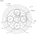
Fig. 3 ] Lafigure 3 est une vue schématique et en coupe transversale d'un exemple de réducteur mécanique ; - [
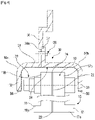
Fig. 4 ] Lafigure 4 est une vue schématique et partielle d'une pièce mécanique de turbomachine telle qu'une gouttière selon l'invention ; - [
Fig. 5 ] Lafigure 5 est une vue schématique, en perspective et partielle d'un exemple de réalisation d'une pièce mécanique de turbomachine avec une surface hydrophobe et/ou lipophobe selon l'invention ; - [
Fig. 6 ] Lafigure 6 est une vue schématique, en perspective et partielle d'un autre exemple de réalisation d'une pièce mécanique de turbomachine avec une surface hydrophobe et/ou lipophobe selon l'invention ; - [
Fig. 7 ] Lafigure 7 est une vue très schématique d'exemples de texturation de surface pour une pièce mécanique selon l'invention, et - [
Fig. 8 ] Lafigure 8 est une vue très schématique et en coupe d'une pièce mécanique de turbomachine, dont des surfaces comportent des revêtements hydrophobes et/ou lipophobes selon l'invention. - La
figure 1 montre une turbomachine qui est destinée à être montée sur un aéronef. La turbomachine illustrée est une turbomachine double flux mais l'invention n'est pas limitée à cette turbomachine. La turbomachine peut être un turbopropulseur et comprendre une seule hélice ou un doublet d'hélices contrarotatives tournant autour d'un axe longitudinal et désignée par l'expression « open rotor » en anglais pour hélice(s) non carénées. La turbomachine peut être aussi un turbomoteur. - De manière générale, une turbomachine 1 double flux, d'axe longitudinal X, comprend d'amont en aval et dans le sens d'écoulement des flux de gaz, une section de compresseur, une chambre de combustion 1c, et une section de turbine. La section de compresseur peut comprendre un compresseur basse pression 1a et un compresseur haute pression 1b. La section de turbine peut comprendre une turbine basse pression 1e et une turbine haute pression 1d. Les compresseurs, la chambre de combustion et les turbines forment un générateur de gaz. Le compresseur haute pression 1b et la turbine haute pression 1d sont reliés par un arbre haute pression 2 et forment avec lui un corps haute pression (HP). Le compresseur basse pression 1a et la turbine basse pression 1e sont reliés par un arbre basse pression 3 et forment avec lui un corps basse pression (BP).
- En aval de la turbine basse pression 1e est agencée une tuyère d'échappement 1h permettant l'évacuation des gaz issus de la chambre de combustion 1c vers l'extérieur.
- En amont du compresseur basse pression 1a est montée une soufflante 4. La soufflante 4 est entraînée par un arbre de soufflante 5 lequel est entrainé par l'arbre BP 3 au moyen d'un réducteur mécanique 6. La soufflante 4 comprend une pluralité d'aubes de soufflante 7 qui s'étendent radialement vers l'extérieur depuis un disque de soufflante. Les aubes de soufflante 7 sont délimitées radialement par un carter 8 de soufflante. Ce dernier porte une nacelle accrochée à l'aéronef.
- Le réducteur 6 est formé d'un train d'engrenage et est connu sous l'acronyme anglais RGB pour « Reduction Gear Box ». Le réducteur 6 est généralement de type planétaire ou épicycloïdal. Le réducteur comprend, tel qu'illustré de manière schématique sur la
figure 2 , un solaire 10 (ou planétaire interne), des satellites 11, un porte-satellites 12 et une couronne 13 (ou planétaire externe). Le solaire 10, la couronne 13 et le porte-satellites 12 sont des planétaires car leurs axes de révolution coïncident avec l'axe longitudinal X de la turbomachine. Les satellites ont chacun un axe de révolution différent et sont équirépartis sur le même diamètre de fonctionnement autour de l'axe des planétaires. Ces axes sont parallèles à l'axe longitudinal X. - Dans le présent exemple, le réducteur 6 est ici à train d'engrenage planétaire. L'entrée du réducteur est couplée à l'arbre BP 3 tandis que la sortie du réducteur est couplée à l'arbre de soufflante. En particulier, la couronne 13 est mobile en rotation et le porte-satellites 12 est fixe en rotation.
- Bien que la description qui suit concerne un réducteur à train d'engrenage de type planétaire, elle s'applique également à un train d'engrenage épicycloïdal ou à un train d'engrenage différentiel mécanique dans lequel les trois composants, que sont le porte-satellites, la couronne et le solaire, sont mobiles en rotation, la vitesse de rotation de l'un de ces composants dépendant notamment de la différence de vitesses des deux autres composants.
- Le réducteur 6 est positionné dans la partie amont de la turbomachine. Une structure fixe 14 comporte schématiquement, ici, une partie amont 14a et une partie aval 14b, qui compose le carter moteur ou stator. La structure fixe est agencée de manière à former une enceinte E entourant le réducteur 6. Cette enceinte E est ici fermée en amont par des joints au niveau d'un palier amont permettant la traversée de l'arbre de soufflante 5, et en aval par des joints au niveau de la traversée de l'arbre BP 3. Le palier amont permet de porter et de guider en rotation l'arbre de soufflante 5 afin de supporter les charges radiales et axiales que subit celui-ci. Ce palier amont est monté dans l'enceinte E. Deux paliers amont peuvent être prévus pour guide l'arbre de soufflante 5 en rotation comme illustré sur la
figure 2 . - Les
figures 2 et3 montrent le réducteur 6 qui peut prendre la forme de différentes architectures selon si certaines pièces sont fixes ou en rotation. En entrée, le réducteur 6 est relié à l'arbre BP 3, par exemple par l'intermédiaire de cannelures internes 15. Ainsi l'arbre BP 3 entraîne le solaire. Classiquement, le solaire 10, dont l'axe de rotation est confondu avec celui de la turbomachine X, entraîne les satellites 11, qui sont équirépartis sur le même diamètre autour de l'axe de rotation X. Ce diamètre est égal au double de l'entraxe de fonctionnement entre le solaire 10 et les satellites 11. Le nombre de satellites 11 est généralement défini entre trois et sept pour ce type d'application. - L'ensemble des satellites 11 est maintenu par un châssis qui est le porte-satellites 12. Chaque satellite 11, sous forme de pignon, tourne autour de son propre axe Y, et engrène avec la couronne 13. En sortie, l'ensemble des satellites 11 est maintenu par le porte-satellites 10 qui est fixé au carter moteur ou stator 14. Chaque satellite entraine la couronne 13 qui est rapportée à l'arbre de soufflante 4. Un porte-couronne 16 est prévu pour relier l'arbre de soufflante 10 à la couronne 13. Les satellites 11 sont montés libres en rotation à l'aide de paliers, par exemple de type roulement ou palier hydrostatique. Chaque palier est monté sur un des axes du porte-satellites et tous les axes sont positionnés les uns par rapport aux autres à l'aide d'un ou plusieurs châssis structurels du porte-satellites.
- Sur la
figure 4 , la couronne 13 est pourvue d'une denture interne qui engrène avec la denture des satellites. Dans le présent exemple de réalisation, la couronne 13 est formée en deux parties (soit deux demi-couronnes). Une demi-couronne aval 17 est constituée d'une jante 17a et d'une demi-bride de fixation 17b. La bride 17b s'étend radialement vers l'extérieur. Une demi-couronne amont 18 est constituée d'une jante 18a et d'une demi-bride de fixation 18b. La bride 18b s'étend radialement vers l'extérieur. La jante 17a comprend une portion de denture amont sous forme d'hélice amont de la denture du réducteur. Cette hélice amont engrène avec celle du satellite 11 qui engrène avec celle du solaire 10. La jante 18a quant à celle-ci comprend une portion de denture aval également sous forme d'hélice aval de la denture du réducteur. Cette hélice aval engrène avec celle du satellite 11 qui engrène avec celle du solaire 10. Une telle configuration permet de fabriquer encore plus facilement la couronne et de faciliter la récupération de l'huile. Si les largeurs d'hélice varient entre le solaire 10, les satellites 11 et la couronne 13 à cause des recouvrements de denture, elles sont toutes centrées sur un plan médian pour les hélices amont et sur un autre plan médian pour les hélices aval. - La demi-bride de fixation 17b de la demi-couronne aval et la demi-bride de fixation 18b de la demi-couronne amont forment la bride de fixation 19 de la couronne. La couronne 13 est fixée au porte-couronne en assemblant la bride de fixation 19 de la couronne et une bride de fixation du porte-couronne. Cette fixation est réalisée à l'aide d'organes de fixation 20 tels que des vis, des boulons et/ou écrous.
- En fonctionnement, l'huile arrive dans le réducteur 6 depuis la partie stator 14 via un distributeur (non représenté) par différents moyens qui sont spécifiques à un ou plusieurs types d'architecture. Le distributeur est séparé en deux parties et en général chacune répétée du même nombre de satellites. Le distributeur comprend des injecteurs 21a (cf.
figure 3 ) qui ont pour fonction de lubrifier les dentures des roues et/ou pignons du réducteur et des bras qui ont pour fonction de lubrifier les paliers du réducteur. L'huile est amenée vers les injecteurs 21a pour ressortir par des extrémités afin de lubrifier par de l'huile dite froide (HF) les dentures des satellites 11, du solaire 10 et aussi de la couronne 13. L'huile est également amenée vers le bras et circule via la bouche d'alimentation du palier. L'huile circule ensuite à travers l'axe dans une ou des zones tampons pour ensuite ressortir par les orifices afin de lubrifier les paliers des satellites. - En référence à la
figure 3 et du fait des forces centrifuges, de l'huile dite chaude HC de lubrification des dentures est projetée radialement vers l'extérieur par rapport aux axes Y des satellites. L'huile chaude est également projetée et éjectée par effet centrifuge de la couronne 13. L'huile est en particulier éjectée radialement vers l'extérieur au niveau de la bride de fixation 19 via des moyens d'éjection d'huile. Les moyens d'éjection comprennent ici un ou plusieurs canaux qui sont régulièrement formés entre les deux demi-couronnes et sur toute la circonférence de la couronne 13. - De manière avantageuse, mais non limitativement, des premiers canaux 22 s'étendent sensiblement suivant l'axe radial Z. Chaque premier canal 22 s'étend radialement entre un orifice d'entrée 23 défini dans une surface interne de la couronne (et qui comprend la denture) et un orifice de sortie 24 défini sur la périphérie de la bride de fixation 19. Préférentiellement, mais non limitativement, il y a plusieurs orifices de sortie 24 répartis circonférentiellement sur la périphérie de la bride 19. L'huile circule depuis l'intérieur de la couronne 13 vers l'extérieur de cette dernière via le ou les canaux 22. Des deuxièmes canaux peuvent également permettre d'évacuer l'huile circulant sur la périphérie externe de la couronne vers les premiers canaux 22.
- En référence à la
figure 4 , la turbomachine est également équipée d'un dispositif de récupération d'huile qui est prévu pour récupérer et évacuer rapidement l'huile éjectée par effet centrifuge du réducteur 6 et aussi de l'enceinte E. Le dispositif de récupération comprend une gouttière 30 de récupération d'huile, annulaire, qui est destinée à récupérer l'huile éjectée du réducteur 6. La gouttière 30, centrée sur l'axe longitudinal X, est agencée autour de la couronne 13. La gouttière 30 est fixée à une structure fixe de la turbomachine (stator). Avantageusement, la gouttière 30 est fixée à l'enceinte E enveloppant le réducteur. La gouttière 30 présente une section axiale en forme générale en U. La gouttière 30 comprend plus précisément une paroi de fond 31 depuis laquelle s'étendent une première paroi latérale 32 et une deuxième paroi latérale 33. La paroi de fond 31 et les parois latérales 32, 33 sont annulaires et centrées sur l'axe longitudinal X. Les parois latérales 32, 33 s'étendent sensiblement radialement (perpendiculaires à l'axe longitudinal X). - La paroi de fond 31 est disposée radialement à l'extérieur de la couronne 13 et est orientée en regard des moyens d'éjection d'huile. Les parois latérales 32, 33 (dites première et deuxième parois) sont disposées de part et d'autre de la bride de fixation 19 suivant l'axe longitudinal. Comme nous pouvons le voir sur la
figure 4 , la gouttière 30 comprend une surface 34 profilée, ici interne, qui est en regard du réducteur 6 et de la couronne 13. Chaque paroi latérale 32, 33 comprend un bord périphérique 35 délimitant un diamètre interne de la gouttière qui est inférieur au diamètre externe de la couronne 13 défini par la périphérie de la bride de fixation 19. De même l'axe des organes de fixation 20 de la bride de fixation 19 délimite un diamètre qui est supérieur au diamètre interne des bords périphériques 35. Une telle configuration permet d'éviter les phénomènes d'aspiration de l'air extérieur à la gouttière vers l'intérieur de la gouttière. Pour renforcer cet avantage, la paroi de fond 31 et les parois latérales 32, 33 sont disposées à une distance prédéterminée de la bride de fixation 19, notamment sa périphérie et des organes de fixation 19. Ces distances prédéterminées tiennent compte des déplacements axiaux de la couronne au cours du fonctionnement du réducteur, des tolérances de fabrication et de la dilatation thermique des pièces. - Dans l'exemple qui est représenté, la gouttière 30 est formée de deux parties afin de faciliter le montage et le démontage de celle-ci dans la turbomachine. Bien évidemment la gouttière peut être formée d'une seule pièce (venue de matière). La gouttière 30 comprend une première partie 30a et une deuxième partie 30b. La première partie 30a comprend une première patte 36, la première paroi latérale 32 et une portion de paroi de fond reliant la première patte 36 et la première paroi latérale 32. La deuxième partie 30b comprend une deuxième patte 37, la deuxième paroi latérale 33 et une portion de paroi de fond reliant la deuxième patte 37 et la deuxième paroi latérale 33. Les première et deuxième pattes 36, 37 s'étendent radialement vers l'extérieur. En particulier, les première et deuxième pattes 36, 37 comprennent chacune une surface d'appui définie dans un plan, et ces plans sont parallèles. La première partie et la deuxième partie sont fixées ensemble au niveau des première et deuxième pattes. Des organes de fixation 38 permettent de fixer les pattes 36, 37 entre elles. Les organes de fixation 38 comprennent des vis, des écrous, des boulons ou tout autre organe adéquat. Dans cet exemple de réalisation, la première patte 35 comprend un renfoncement annulaire 36a destiné à recevoir une partie de la deuxième patte 37. La surface interne des portions de parois de fond et des parois latérales présentent une continuité de surface et sont affleurantes. La première patte 36, qui présente une longueur supérieure à la deuxième patte 37, permet la fixation de la gouttière 30 à la structure fixe de la turbomachine.
- Suivant une autre alternative, la gouttière 30 comprend une unique patte radiale permettant la fixation sur la structure fixe de la turbomachine.
- La gouttière 30 est réalisée dans un matériau métallique. Le matériau métallique peut être de l'acier ou du titane. De manière avantageuse, mais non limitativement, la gouttière 30 est réalisée à partir d'une tôle pour alléger le poids de celle-ci. Les parois 31, 32, 33 sont obtenues par pliage ou par soudage. Le pliage et le soudage sont faciles et rapides à mettre en oeuvre et nécessitent très peu d'outillage pour fabriquer la gouttière.
- La
figure 5 montre un premier mode de réalisation d'une gouttière 30 dans lequel la surface 34 profilée, interne, comprend un revêtement hydrophobe et/ou lipophobe ou une texturation de surface rendant ladite surface hydrophobe et/ou lipophobe. Dans la présente description, nous entendons par les termes « hydrophobe » et « lipophobe » (et voire « oléophobe ») la capacité d'une surface à repousser de l'eau et/ou de l'huile de ladite surface pour diminuer la surface de contact entre la surface et la goutte qui est formée. De telles propriétés permettent alors de diminuer le coefficient de friction. Le revêtement ou la surface texturée permet un coefficient de friction plus petit entre la surface de l'eau et/ou l'huile et la surface métallique avec le revêtement. Plus précisément encore, le caractère lipophobe et/ou hydrophobe permet au fluide (eau/huile/ graisse) de perler (forme des perles) lorsque celui-ci arrose la pièce mécanique, ce qui contribue a une bonne évacuation de ce fluide. De même, nous comprenons aussi par « plus lipophobe/hydrophobe » que la surface est moins lipophile/hydrophile, à savoir le fluide aura moins tendance à s'étaler/rester sur la surface. - Le revêtement ou la texturation s'étend sur toute la surface interne des parois latérales et de la paroi de fond.
- La
figure 6 montre un second mode de réalisation de la gouttière 30 dans lequel uniquement la surface des parois latérales 32, 33 comprend un revêtement ou une texturation de surface. Autrement dit, la surface de la paroi de fond est dépourvue de revêtement ou texturation. - Suivant une alternative non représentée, le revêtement ou la texturation de surface s'étend ainsi sur des zones prédéterminées des parois latérales 32, 33 et/ou de la paroi de fond 31. Les zones prédéterminées peuvent correspondre à des bandes annulaires en regard des organes de fixation 38 et/ou de la bride de fixation 09. Dans le cas des zones annulaires prévues sur les parois latérales, celles-ci seraient éloignées des bords périphériques 34 de parois latérales 32, 33. Dans le cas de la zone de la paroi de fond, celle-ci serait éloignée des parois latérales.
- La
figure 7 montre différents exemples de texturation de surface 39 pour toute la surface ou certaines zones de la surface. - La texturation de surface 39 comprend de préférence une répétition surfacique de motifs en creux ou bosse de dimensions micrométriques. Les dimensions peuvent être également être de l'ordre du nanomètre. Les motifs peuvent être linéaires ou ponctuels. La texturation 38 est avantageusement, mais non limitativement, réalisée à l'aide d'un procédé de micro-usinage par enlèvement de matière. Un exemple de procédé de micro-usinage est le micro-usinage laser.
- Les motifs en creux ou bosses permettent de diminuer l'aire de la surface en contact avec le fluide contenant de l'eau et/ou de l'huile et ainsi de réduire la friction de l'eau et/ou de l'huile avec la surface. De la sorte, les motifs ont pour effet de repousser le fluide qui s'écoule ou se déplace plus rapidement sur le revêtement ou la surface texturée.
- La
figure 8 montre un exemple de revêtement hydrophobe et/lipophobe 40 destiné à revêtir la surface interne des parois latérales et/ou de la paroi des fond ou certaines zones prédéterminées de celle-ci. - Le revêtement hydrophobe et/ou lipophobe 40 est de préférence en polymère, et en particulier un fluopolymère tel qu'un polytétrafluoroéthylène (PTFE). Il a par exemple une épaisseur comprise entre 1 et 100 µm. Il peut être obtenu par pulvérisation d'une solution sur la surface interne chaque surface et chauffage en vue de la polymérisation et durcissement du revêtement.
- Ainsi la pièce mécanique, ici la gouttière 30 de récupération d'huile, équipée d'un tel revêtement 40 ou d'une telle texturation 39 facilite la récupération et l'évacuation de l'huile. L'écoulement est facilité du fait qu'en diminuant le coefficient d'étalement de l'huile, nous augmentons la vitesse et ainsi le débit d'évacuation de la gouttière. Cette évacuation est importante notamment dans les phases de fonctionnement ou de vol de l'aéronef où le réducteur a besoin d'un débit important d'huile tel que lors du décollage.
- Le revêtement hydrophobe et/ou lipophobe, et la texturation apportent les mêmes avantages évoqués plus haut. L'avantage de la texturation par rapport au revêtement est qu'elle n'introduit pas d'éventuels polluants car le revêtement est susceptible de se dégrader en fonctionnement et de relarguer des éléments non désirés dans le moteur.
Claims (9)
- Pièce mécanique (30) pour une turbomachine d'aéronef, la pièce mécanique étant réalisée en métal et comportant au moins une surface (34) profilée configurée pour assurer un écoulement d'huile en fonctionnement, caractérisée en ce que ladite surface (34) comprend un revêtement (40) plus hydrophobe et/ou lipophobe que ladite surface (34) ou une texturation de surface (39) rendant ladite surface plus hydrophobe et/ou lipophobe, la pièce étant une gouttière (30) de récupération d'huile de lubrification, annulaire, en particulier pour un réducteur mécanique (6).
- Pièce mécanique (30) selon la revendication 1, caractérisée en ce que la surface (34) est en regard de moyens d'éjection d'huile.
- Pièce mécanique (30) selon l'une des revendications 1 à 2, caractérisée en ce que ledit revêtement (40) ou ladite texturation (38) s'étend sur une partie seulement de ladite surface (34).
- Pièce mécanique (30) selon l'une des revendications 1 à 2, caractérisée en ce que ledit revêtement (40) ou ladite texturation (39) s'étend sur la totalité de ladite surface (34).
- Pièce mécanique selon l'une des revendications 1 à 4, caractérisée en ce qu'elle s'étend circonférentiellement autour d'un axe et présente en coupe une forme de U, la forme en U comprenant deux parois latérales (32, 33) opposées et une paroi de fond (31), la surface (34) étant au moins une surface de la paroi de fond (31) et ces parois étant configurées pour assurer un écoulement d'huile en fonctionnement, au moins une partie de la surface (34) comprenant un revêtement hydrophobe et/ou lipophobe (40) ou une texturation de surface (39) rendant ladite surface hydrophobe et/ou lipophobe.
- Pièce mécanique (30) selon l'une des revendications 1 à 5, dans laquelle le revêtement hydrophobe (40) est en polymère, et en particulier un fluopolymère tel qu'un polytétrafluoroéthylène.
- Pièce mécanique (30) selon l'une des revendications 1 à 5, caractérisée en ce que la texturation de surface (39) comprend une répétition surfacique de motifs en creux ou des bosses de dimensions micrométriques ou nanométriques, réalisés par exemple par laser.
- Réducteur mécanique (6) pour une turbomachine d'aéronef, le réducteur mécanique étant à train d'engrenage planétaire et comportant un solaire (10), une couronne (13) s'étendant autour du solaire, des satellites (11) engrenés avec le solaire (10) et la couronne (13), et une pièce mécanique (30) selon l'une des revendications précédentes formant une gouttière en étant disposée radialement autour de la couronne (13) de façon à ce que la surface (20a) s'étende autour de la couronne (13).
- Turbomachine (1), en particulier d'aéronef, comportant au moins une pièce mécanique (30) selon l'une des revendications 1 à 7 ou un réducteur mécanique (6) selon la revendication 8.
Applications Claiming Priority (1)
| Application Number | Priority Date | Filing Date | Title |
|---|---|---|---|
| FR2105971A FR3123700A1 (fr) | 2021-06-07 | 2021-06-07 | Piece mecanique pour une turbomachine d’aeronef et turbomachine correspondante. |
Publications (1)
| Publication Number | Publication Date |
|---|---|
| EP4102109A1 true EP4102109A1 (fr) | 2022-12-14 |
Family
ID=76807845
Family Applications (1)
| Application Number | Title | Priority Date | Filing Date |
|---|---|---|---|
| EP22177281.7A Pending EP4102109A1 (fr) | 2021-06-07 | 2022-06-03 | Piece mecanique pour une turbomachine d'aeronef et turbomachine correspondante |
Country Status (4)
| Country | Link |
|---|---|
| US (1) | US12209652B2 (fr) |
| EP (1) | EP4102109A1 (fr) |
| CN (1) | CN115507168A (fr) |
| FR (1) | FR3123700A1 (fr) |
Families Citing this family (1)
| Publication number | Priority date | Publication date | Assignee | Title |
|---|---|---|---|---|
| CN116085116A (zh) * | 2023-03-13 | 2023-05-09 | 西北工业大学 | 一种航空发动机轴承腔壁面及其换热方法 |
Citations (4)
| Publication number | Priority date | Publication date | Assignee | Title |
|---|---|---|---|---|
| JP2011112145A (ja) | 2009-11-26 | 2011-06-09 | Ntn Corp | 遊星歯車の潤滑装置 |
| JP2011185322A (ja) | 2010-03-05 | 2011-09-22 | Ntn Corp | 遊星歯車減速機の潤滑装置 |
| FR3081513A1 (fr) | 2018-05-28 | 2019-11-29 | Safran Aircraft Engines | Systeme de transmission de puissance comprenant un dispositif de recuperation d'huile de lubrification et turbomachine equipee d'un tel systeme de transmission de puissance |
| US20200309032A1 (en) | 2019-03-25 | 2020-10-01 | Rolls-Royce Plc | Apparatus |
Family Cites Families (3)
| Publication number | Priority date | Publication date | Assignee | Title |
|---|---|---|---|---|
| US6777617B2 (en) * | 2002-12-30 | 2004-08-17 | 3M Innovative Properties Company | Telecommunications terminal |
| US10107231B2 (en) * | 2006-08-15 | 2018-10-23 | United Technologies Corporation | Gas turbine engine with geared architecture |
| CN103649240B (zh) * | 2011-01-19 | 2016-09-14 | 哈佛学院院长等 | 具有高压稳定性、光学透明性以及自修复特征的光滑表面 |
-
2021
- 2021-06-07 FR FR2105971A patent/FR3123700A1/fr active Pending
-
2022
- 2022-06-03 US US17/805,380 patent/US12209652B2/en active Active
- 2022-06-03 EP EP22177281.7A patent/EP4102109A1/fr active Pending
- 2022-06-07 CN CN202210652524.3A patent/CN115507168A/zh active Pending
Patent Citations (4)
| Publication number | Priority date | Publication date | Assignee | Title |
|---|---|---|---|---|
| JP2011112145A (ja) | 2009-11-26 | 2011-06-09 | Ntn Corp | 遊星歯車の潤滑装置 |
| JP2011185322A (ja) | 2010-03-05 | 2011-09-22 | Ntn Corp | 遊星歯車減速機の潤滑装置 |
| FR3081513A1 (fr) | 2018-05-28 | 2019-11-29 | Safran Aircraft Engines | Systeme de transmission de puissance comprenant un dispositif de recuperation d'huile de lubrification et turbomachine equipee d'un tel systeme de transmission de puissance |
| US20200309032A1 (en) | 2019-03-25 | 2020-10-01 | Rolls-Royce Plc | Apparatus |
Also Published As
| Publication number | Publication date |
|---|---|
| US20220390004A1 (en) | 2022-12-08 |
| FR3123700A1 (fr) | 2022-12-09 |
| US12209652B2 (en) | 2025-01-28 |
| CN115507168A (zh) | 2022-12-23 |
Similar Documents
| Publication | Publication Date | Title |
|---|---|---|
| EP3575562B1 (fr) | Système de transmission de puissance comprenant un dispositif de récupération d'huile de lubrification et turbomachine équipée d'un tel système de transmission de puissance | |
| FR3071008B1 (fr) | Aube directrice de sortie pour turbomachine, comprenant un passage de refroidissement de lubrifiant equipe d'une matrice de conduction thermique comprimee entre les parois d'intrados et d'extrados | |
| EP3071792B1 (fr) | Moteur modulaire | |
| EP3763971B1 (fr) | Couvercle de canalisation d'huile et reducteur mecanique de turbomachine d'aeronef comportant un tel couvercle | |
| FR3069300A1 (fr) | Ensemble comportant un rouet de lubrification et des gicleurs de lubrifiant, pour un reducteur de vitesse a train epicycloidal de turbomachine | |
| FR3095252A1 (fr) | Reducteur mecanique de turbomachine d’aeronef | |
| BE1023324A1 (fr) | Crepine pour huile moteur de turbomachine | |
| EP4127412B1 (fr) | Turbomachine d'aeronef equipee d'une machine electrique | |
| FR3084427A1 (fr) | Dispositif de type reducteur mecanique pour une turbomachine | |
| FR3077850A1 (fr) | Aube directrice de sortie pour turbomachine, realisee a partir de plusieurs pieces assemblees entre elles par des moyens de fixation deportes de la veine | |
| FR3054263A1 (fr) | Carter intermediaire de turbomachine d'aeronef realise d'une seule piece de fonderie avec une canalisation de lubrifiant | |
| EP3698050B1 (fr) | Carter extérieur de turbo-compresseur avec réservoir d'huile intégré | |
| EP4056829A1 (fr) | Refroidissement de pignons d'un réducteur mécanique d'une turbomachine | |
| EP4102109A1 (fr) | Piece mecanique pour une turbomachine d'aeronef et turbomachine correspondante | |
| FR3075867A1 (fr) | Dispositif de deshuilage d'une enceinte de lubrification de turbomachine | |
| EP4407149B1 (fr) | Ensemble pour une turbomachine comprenant des moyens d'evacuation de lubrifiant et turbomachine equipee d'un tel ensemble | |
| FR3110630A1 (fr) | Aube directrice de sortie pour turbomachine, realisee a partir de plusieurs pieces assemblees entre elles | |
| EP3647626B1 (fr) | Roue dentee | |
| EP4102108B1 (fr) | Pièce mécanique pour une turbomachine d'aéronef | |
| FR3132732A1 (fr) | Turbomachine pour un aeronef | |
| EP4073364B1 (fr) | Turbomachine à turbine contrarotative pour un aéronef | |
| BE1023377B1 (fr) | Carter a bossages de compresseur de turbomachine axiale | |
| WO2025168906A1 (fr) | Couronne pour un reducteur mecanique d'une turbomachine d'aeronef | |
| EP4001702A1 (fr) | Collecteur d'huile pour un dispositif de transmission de couple d'une turbomachine d'aéronef | |
| FR3148260A1 (fr) | Démarreur de turbine à air |
Legal Events
| Date | Code | Title | Description |
|---|---|---|---|
| PUAI | Public reference made under article 153(3) epc to a published international application that has entered the european phase |
Free format text: ORIGINAL CODE: 0009012 |
|
| STAA | Information on the status of an ep patent application or granted ep patent |
Free format text: STATUS: REQUEST FOR EXAMINATION WAS MADE |
|
| 17P | Request for examination filed |
Effective date: 20220603 |
|
| AK | Designated contracting states |
Kind code of ref document: A1 Designated state(s): AL AT BE BG CH CY CZ DE DK EE ES FI FR GB GR HR HU IE IS IT LI LT LU LV MC MK MT NL NO PL PT RO RS SE SI SK SM TR |
|
| STAA | Information on the status of an ep patent application or granted ep patent |
Free format text: STATUS: EXAMINATION IS IN PROGRESS |
|
| 17Q | First examination report despatched |
Effective date: 20231114 |
|
| GRAP | Despatch of communication of intention to grant a patent |
Free format text: ORIGINAL CODE: EPIDOSNIGR1 |
|
| STAA | Information on the status of an ep patent application or granted ep patent |
Free format text: STATUS: GRANT OF PATENT IS INTENDED |
|
| INTG | Intention to grant announced |
Effective date: 20260122 |