EP4101752A1 - System und verfahren zum regasifizieren von verflüssigtem schiffsgas - Google Patents
System und verfahren zum regasifizieren von verflüssigtem schiffsgas Download PDFInfo
- Publication number
- EP4101752A1 EP4101752A1 EP20918026.4A EP20918026A EP4101752A1 EP 4101752 A1 EP4101752 A1 EP 4101752A1 EP 20918026 A EP20918026 A EP 20918026A EP 4101752 A1 EP4101752 A1 EP 4101752A1
- Authority
- EP
- European Patent Office
- Prior art keywords
- heating medium
- gas
- vaporizer
- temperature
- heat exchange
- Prior art date
- Legal status (The legal status is an assumption and is not a legal conclusion. Google has not performed a legal analysis and makes no representation as to the accuracy of the status listed.)
- Granted
Links
Images


Classifications
-
- B—PERFORMING OPERATIONS; TRANSPORTING
- B63—SHIPS OR OTHER WATERBORNE VESSELS; RELATED EQUIPMENT
- B63B—SHIPS OR OTHER WATERBORNE VESSELS; EQUIPMENT FOR SHIPPING
- B63B25/00—Load-accommodating arrangements, e.g. stowing, trimming; Vessels characterised thereby
- B63B25/02—Load-accommodating arrangements, e.g. stowing, trimming; Vessels characterised thereby for bulk goods
- B63B25/08—Load-accommodating arrangements, e.g. stowing, trimming; Vessels characterised thereby for bulk goods fluid
- B63B25/12—Load-accommodating arrangements, e.g. stowing, trimming; Vessels characterised thereby for bulk goods fluid closed
- B63B25/16—Load-accommodating arrangements, e.g. stowing, trimming; Vessels characterised thereby for bulk goods fluid closed heat-insulated
-
- F—MECHANICAL ENGINEERING; LIGHTING; HEATING; WEAPONS; BLASTING
- F17—STORING OR DISTRIBUTING GASES OR LIQUIDS
- F17C—VESSELS FOR CONTAINING OR STORING COMPRESSED, LIQUEFIED OR SOLIDIFIED GASES; FIXED-CAPACITY GAS-HOLDERS; FILLING VESSELS WITH, OR DISCHARGING FROM VESSELS, COMPRESSED, LIQUEFIED, OR SOLIDIFIED GASES
- F17C9/00—Methods or apparatus for discharging liquefied or solidified gases from vessels not under pressure
- F17C9/02—Methods or apparatus for discharging liquefied or solidified gases from vessels not under pressure with change of state, e.g. vaporisation
- F17C9/04—Recovery of thermal energy
-
- B—PERFORMING OPERATIONS; TRANSPORTING
- B63—SHIPS OR OTHER WATERBORNE VESSELS; RELATED EQUIPMENT
- B63B—SHIPS OR OTHER WATERBORNE VESSELS; EQUIPMENT FOR SHIPPING
- B63B13/00—Conduits for emptying or ballasting; Self-bailing equipment; Scuppers
-
- B—PERFORMING OPERATIONS; TRANSPORTING
- B63—SHIPS OR OTHER WATERBORNE VESSELS; RELATED EQUIPMENT
- B63J—AUXILIARIES ON VESSELS
- B63J3/00—Driving of auxiliaries
- B63J3/04—Driving of auxiliaries from power plant other than propulsion power plant
-
- F—MECHANICAL ENGINEERING; LIGHTING; HEATING; WEAPONS; BLASTING
- F17—STORING OR DISTRIBUTING GASES OR LIQUIDS
- F17C—VESSELS FOR CONTAINING OR STORING COMPRESSED, LIQUEFIED OR SOLIDIFIED GASES; FIXED-CAPACITY GAS-HOLDERS; FILLING VESSELS WITH, OR DISCHARGING FROM VESSELS, COMPRESSED, LIQUEFIED, OR SOLIDIFIED GASES
- F17C13/00—Details of vessels or of the filling or discharging of vessels
- F17C13/02—Special adaptations of indicating, measuring, or monitoring equipment
- F17C13/025—Special adaptations of indicating, measuring, or monitoring equipment having the pressure as the parameter
-
- F—MECHANICAL ENGINEERING; LIGHTING; HEATING; WEAPONS; BLASTING
- F17—STORING OR DISTRIBUTING GASES OR LIQUIDS
- F17C—VESSELS FOR CONTAINING OR STORING COMPRESSED, LIQUEFIED OR SOLIDIFIED GASES; FIXED-CAPACITY GAS-HOLDERS; FILLING VESSELS WITH, OR DISCHARGING FROM VESSELS, COMPRESSED, LIQUEFIED, OR SOLIDIFIED GASES
- F17C13/00—Details of vessels or of the filling or discharging of vessels
- F17C13/02—Special adaptations of indicating, measuring, or monitoring equipment
- F17C13/026—Special adaptations of indicating, measuring, or monitoring equipment having the temperature as the parameter
-
- F—MECHANICAL ENGINEERING; LIGHTING; HEATING; WEAPONS; BLASTING
- F17—STORING OR DISTRIBUTING GASES OR LIQUIDS
- F17C—VESSELS FOR CONTAINING OR STORING COMPRESSED, LIQUEFIED OR SOLIDIFIED GASES; FIXED-CAPACITY GAS-HOLDERS; FILLING VESSELS WITH, OR DISCHARGING FROM VESSELS, COMPRESSED, LIQUEFIED, OR SOLIDIFIED GASES
- F17C13/00—Details of vessels or of the filling or discharging of vessels
- F17C13/04—Arrangement or mounting of valves
-
- F—MECHANICAL ENGINEERING; LIGHTING; HEATING; WEAPONS; BLASTING
- F17—STORING OR DISTRIBUTING GASES OR LIQUIDS
- F17C—VESSELS FOR CONTAINING OR STORING COMPRESSED, LIQUEFIED OR SOLIDIFIED GASES; FIXED-CAPACITY GAS-HOLDERS; FILLING VESSELS WITH, OR DISCHARGING FROM VESSELS, COMPRESSED, LIQUEFIED, OR SOLIDIFIED GASES
- F17C9/00—Methods or apparatus for discharging liquefied or solidified gases from vessels not under pressure
-
- F—MECHANICAL ENGINEERING; LIGHTING; HEATING; WEAPONS; BLASTING
- F17—STORING OR DISTRIBUTING GASES OR LIQUIDS
- F17C—VESSELS FOR CONTAINING OR STORING COMPRESSED, LIQUEFIED OR SOLIDIFIED GASES; FIXED-CAPACITY GAS-HOLDERS; FILLING VESSELS WITH, OR DISCHARGING FROM VESSELS, COMPRESSED, LIQUEFIED, OR SOLIDIFIED GASES
- F17C2221/00—Handled fluid, in particular type of fluid
- F17C2221/03—Mixtures
- F17C2221/032—Hydrocarbons
- F17C2221/033—Methane, e.g. natural gas, CNG, LNG, GNL, GNC, PLNG
-
- F—MECHANICAL ENGINEERING; LIGHTING; HEATING; WEAPONS; BLASTING
- F17—STORING OR DISTRIBUTING GASES OR LIQUIDS
- F17C—VESSELS FOR CONTAINING OR STORING COMPRESSED, LIQUEFIED OR SOLIDIFIED GASES; FIXED-CAPACITY GAS-HOLDERS; FILLING VESSELS WITH, OR DISCHARGING FROM VESSELS, COMPRESSED, LIQUEFIED, OR SOLIDIFIED GASES
- F17C2223/00—Handled fluid before transfer, i.e. state of fluid when stored in the vessel or before transfer from the vessel
- F17C2223/01—Handled fluid before transfer, i.e. state of fluid when stored in the vessel or before transfer from the vessel characterised by the phase
- F17C2223/0146—Two-phase
- F17C2223/0153—Liquefied gas, e.g. LPG, GPL
- F17C2223/0161—Liquefied gas, e.g. LPG, GPL cryogenic, e.g. LNG, GNL, PLNG
-
- F—MECHANICAL ENGINEERING; LIGHTING; HEATING; WEAPONS; BLASTING
- F17—STORING OR DISTRIBUTING GASES OR LIQUIDS
- F17C—VESSELS FOR CONTAINING OR STORING COMPRESSED, LIQUEFIED OR SOLIDIFIED GASES; FIXED-CAPACITY GAS-HOLDERS; FILLING VESSELS WITH, OR DISCHARGING FROM VESSELS, COMPRESSED, LIQUEFIED, OR SOLIDIFIED GASES
- F17C2223/00—Handled fluid before transfer, i.e. state of fluid when stored in the vessel or before transfer from the vessel
- F17C2223/03—Handled fluid before transfer, i.e. state of fluid when stored in the vessel or before transfer from the vessel characterised by the pressure level
- F17C2223/033—Small pressure, e.g. for liquefied gas
-
- F—MECHANICAL ENGINEERING; LIGHTING; HEATING; WEAPONS; BLASTING
- F17—STORING OR DISTRIBUTING GASES OR LIQUIDS
- F17C—VESSELS FOR CONTAINING OR STORING COMPRESSED, LIQUEFIED OR SOLIDIFIED GASES; FIXED-CAPACITY GAS-HOLDERS; FILLING VESSELS WITH, OR DISCHARGING FROM VESSELS, COMPRESSED, LIQUEFIED, OR SOLIDIFIED GASES
- F17C2223/00—Handled fluid before transfer, i.e. state of fluid when stored in the vessel or before transfer from the vessel
- F17C2223/04—Handled fluid before transfer, i.e. state of fluid when stored in the vessel or before transfer from the vessel characterised by other properties of handled fluid before transfer
- F17C2223/042—Localisation of the removal point
- F17C2223/046—Localisation of the removal point in the liquid
-
- F—MECHANICAL ENGINEERING; LIGHTING; HEATING; WEAPONS; BLASTING
- F17—STORING OR DISTRIBUTING GASES OR LIQUIDS
- F17C—VESSELS FOR CONTAINING OR STORING COMPRESSED, LIQUEFIED OR SOLIDIFIED GASES; FIXED-CAPACITY GAS-HOLDERS; FILLING VESSELS WITH, OR DISCHARGING FROM VESSELS, COMPRESSED, LIQUEFIED, OR SOLIDIFIED GASES
- F17C2225/00—Handled fluid after transfer, i.e. state of fluid after transfer from the vessel
- F17C2225/01—Handled fluid after transfer, i.e. state of fluid after transfer from the vessel characterised by the phase
- F17C2225/0107—Single phase
- F17C2225/0123—Single phase gaseous, e.g. CNG, GNC
-
- F—MECHANICAL ENGINEERING; LIGHTING; HEATING; WEAPONS; BLASTING
- F17—STORING OR DISTRIBUTING GASES OR LIQUIDS
- F17C—VESSELS FOR CONTAINING OR STORING COMPRESSED, LIQUEFIED OR SOLIDIFIED GASES; FIXED-CAPACITY GAS-HOLDERS; FILLING VESSELS WITH, OR DISCHARGING FROM VESSELS, COMPRESSED, LIQUEFIED, OR SOLIDIFIED GASES
- F17C2225/00—Handled fluid after transfer, i.e. state of fluid after transfer from the vessel
- F17C2225/03—Handled fluid after transfer, i.e. state of fluid after transfer from the vessel characterised by the pressure level
- F17C2225/035—High pressure, i.e. between 10 and 80 bars
-
- F—MECHANICAL ENGINEERING; LIGHTING; HEATING; WEAPONS; BLASTING
- F17—STORING OR DISTRIBUTING GASES OR LIQUIDS
- F17C—VESSELS FOR CONTAINING OR STORING COMPRESSED, LIQUEFIED OR SOLIDIFIED GASES; FIXED-CAPACITY GAS-HOLDERS; FILLING VESSELS WITH, OR DISCHARGING FROM VESSELS, COMPRESSED, LIQUEFIED, OR SOLIDIFIED GASES
- F17C2227/00—Transfer of fluids, i.e. method or means for transferring the fluid; Heat exchange with the fluid
- F17C2227/01—Propulsion of the fluid
- F17C2227/0128—Propulsion of the fluid with pumps or compressors
- F17C2227/0135—Pumps
-
- F—MECHANICAL ENGINEERING; LIGHTING; HEATING; WEAPONS; BLASTING
- F17—STORING OR DISTRIBUTING GASES OR LIQUIDS
- F17C—VESSELS FOR CONTAINING OR STORING COMPRESSED, LIQUEFIED OR SOLIDIFIED GASES; FIXED-CAPACITY GAS-HOLDERS; FILLING VESSELS WITH, OR DISCHARGING FROM VESSELS, COMPRESSED, LIQUEFIED, OR SOLIDIFIED GASES
- F17C2227/00—Transfer of fluids, i.e. method or means for transferring the fluid; Heat exchange with the fluid
- F17C2227/03—Heat exchange with the fluid
- F17C2227/0302—Heat exchange with the fluid by heating
- F17C2227/0309—Heat exchange with the fluid by heating using another fluid
- F17C2227/0316—Water heating
- F17C2227/0318—Water heating using seawater
-
- F—MECHANICAL ENGINEERING; LIGHTING; HEATING; WEAPONS; BLASTING
- F17—STORING OR DISTRIBUTING GASES OR LIQUIDS
- F17C—VESSELS FOR CONTAINING OR STORING COMPRESSED, LIQUEFIED OR SOLIDIFIED GASES; FIXED-CAPACITY GAS-HOLDERS; FILLING VESSELS WITH, OR DISCHARGING FROM VESSELS, COMPRESSED, LIQUEFIED, OR SOLIDIFIED GASES
- F17C2227/00—Transfer of fluids, i.e. method or means for transferring the fluid; Heat exchange with the fluid
- F17C2227/03—Heat exchange with the fluid
- F17C2227/0302—Heat exchange with the fluid by heating
- F17C2227/0309—Heat exchange with the fluid by heating using another fluid
- F17C2227/0323—Heat exchange with the fluid by heating using another fluid in a closed loop
-
- F—MECHANICAL ENGINEERING; LIGHTING; HEATING; WEAPONS; BLASTING
- F17—STORING OR DISTRIBUTING GASES OR LIQUIDS
- F17C—VESSELS FOR CONTAINING OR STORING COMPRESSED, LIQUEFIED OR SOLIDIFIED GASES; FIXED-CAPACITY GAS-HOLDERS; FILLING VESSELS WITH, OR DISCHARGING FROM VESSELS, COMPRESSED, LIQUEFIED, OR SOLIDIFIED GASES
- F17C2227/00—Transfer of fluids, i.e. method or means for transferring the fluid; Heat exchange with the fluid
- F17C2227/03—Heat exchange with the fluid
- F17C2227/0367—Localisation of heat exchange
- F17C2227/0388—Localisation of heat exchange separate
- F17C2227/0393—Localisation of heat exchange separate using a vaporiser
-
- F—MECHANICAL ENGINEERING; LIGHTING; HEATING; WEAPONS; BLASTING
- F17—STORING OR DISTRIBUTING GASES OR LIQUIDS
- F17C—VESSELS FOR CONTAINING OR STORING COMPRESSED, LIQUEFIED OR SOLIDIFIED GASES; FIXED-CAPACITY GAS-HOLDERS; FILLING VESSELS WITH, OR DISCHARGING FROM VESSELS, COMPRESSED, LIQUEFIED, OR SOLIDIFIED GASES
- F17C2250/00—Accessories; Control means; Indicating, measuring or monitoring of parameters
- F17C2250/04—Indicating or measuring of parameters as input values
- F17C2250/0404—Parameters indicated or measured
- F17C2250/043—Pressure
-
- F—MECHANICAL ENGINEERING; LIGHTING; HEATING; WEAPONS; BLASTING
- F17—STORING OR DISTRIBUTING GASES OR LIQUIDS
- F17C—VESSELS FOR CONTAINING OR STORING COMPRESSED, LIQUEFIED OR SOLIDIFIED GASES; FIXED-CAPACITY GAS-HOLDERS; FILLING VESSELS WITH, OR DISCHARGING FROM VESSELS, COMPRESSED, LIQUEFIED, OR SOLIDIFIED GASES
- F17C2250/00—Accessories; Control means; Indicating, measuring or monitoring of parameters
- F17C2250/04—Indicating or measuring of parameters as input values
- F17C2250/0404—Parameters indicated or measured
- F17C2250/0439—Temperature
-
- F—MECHANICAL ENGINEERING; LIGHTING; HEATING; WEAPONS; BLASTING
- F17—STORING OR DISTRIBUTING GASES OR LIQUIDS
- F17C—VESSELS FOR CONTAINING OR STORING COMPRESSED, LIQUEFIED OR SOLIDIFIED GASES; FIXED-CAPACITY GAS-HOLDERS; FILLING VESSELS WITH, OR DISCHARGING FROM VESSELS, COMPRESSED, LIQUEFIED, OR SOLIDIFIED GASES
- F17C2250/00—Accessories; Control means; Indicating, measuring or monitoring of parameters
- F17C2250/04—Indicating or measuring of parameters as input values
- F17C2250/0404—Parameters indicated or measured
- F17C2250/0443—Flow or movement of content
-
- F—MECHANICAL ENGINEERING; LIGHTING; HEATING; WEAPONS; BLASTING
- F17—STORING OR DISTRIBUTING GASES OR LIQUIDS
- F17C—VESSELS FOR CONTAINING OR STORING COMPRESSED, LIQUEFIED OR SOLIDIFIED GASES; FIXED-CAPACITY GAS-HOLDERS; FILLING VESSELS WITH, OR DISCHARGING FROM VESSELS, COMPRESSED, LIQUEFIED, OR SOLIDIFIED GASES
- F17C2260/00—Purposes of gas storage and gas handling
- F17C2260/04—Reducing risks and environmental impact
- F17C2260/046—Enhancing energy recovery
-
- F—MECHANICAL ENGINEERING; LIGHTING; HEATING; WEAPONS; BLASTING
- F17—STORING OR DISTRIBUTING GASES OR LIQUIDS
- F17C—VESSELS FOR CONTAINING OR STORING COMPRESSED, LIQUEFIED OR SOLIDIFIED GASES; FIXED-CAPACITY GAS-HOLDERS; FILLING VESSELS WITH, OR DISCHARGING FROM VESSELS, COMPRESSED, LIQUEFIED, OR SOLIDIFIED GASES
- F17C2265/00—Effects achieved by gas storage or gas handling
- F17C2265/03—Treating the boil-off
- F17C2265/032—Treating the boil-off by recovery
-
- F—MECHANICAL ENGINEERING; LIGHTING; HEATING; WEAPONS; BLASTING
- F17—STORING OR DISTRIBUTING GASES OR LIQUIDS
- F17C—VESSELS FOR CONTAINING OR STORING COMPRESSED, LIQUEFIED OR SOLIDIFIED GASES; FIXED-CAPACITY GAS-HOLDERS; FILLING VESSELS WITH, OR DISCHARGING FROM VESSELS, COMPRESSED, LIQUEFIED, OR SOLIDIFIED GASES
- F17C2265/00—Effects achieved by gas storage or gas handling
- F17C2265/05—Regasification
-
- F—MECHANICAL ENGINEERING; LIGHTING; HEATING; WEAPONS; BLASTING
- F17—STORING OR DISTRIBUTING GASES OR LIQUIDS
- F17C—VESSELS FOR CONTAINING OR STORING COMPRESSED, LIQUEFIED OR SOLIDIFIED GASES; FIXED-CAPACITY GAS-HOLDERS; FILLING VESSELS WITH, OR DISCHARGING FROM VESSELS, COMPRESSED, LIQUEFIED, OR SOLIDIFIED GASES
- F17C2265/00—Effects achieved by gas storage or gas handling
- F17C2265/06—Fluid distribution
-
- F—MECHANICAL ENGINEERING; LIGHTING; HEATING; WEAPONS; BLASTING
- F17—STORING OR DISTRIBUTING GASES OR LIQUIDS
- F17C—VESSELS FOR CONTAINING OR STORING COMPRESSED, LIQUEFIED OR SOLIDIFIED GASES; FIXED-CAPACITY GAS-HOLDERS; FILLING VESSELS WITH, OR DISCHARGING FROM VESSELS, COMPRESSED, LIQUEFIED, OR SOLIDIFIED GASES
- F17C2265/00—Effects achieved by gas storage or gas handling
- F17C2265/06—Fluid distribution
- F17C2265/066—Fluid distribution for feeding engines for propulsion
-
- F—MECHANICAL ENGINEERING; LIGHTING; HEATING; WEAPONS; BLASTING
- F17—STORING OR DISTRIBUTING GASES OR LIQUIDS
- F17C—VESSELS FOR CONTAINING OR STORING COMPRESSED, LIQUEFIED OR SOLIDIFIED GASES; FIXED-CAPACITY GAS-HOLDERS; FILLING VESSELS WITH, OR DISCHARGING FROM VESSELS, COMPRESSED, LIQUEFIED, OR SOLIDIFIED GASES
- F17C2265/00—Effects achieved by gas storage or gas handling
- F17C2265/06—Fluid distribution
- F17C2265/068—Distribution pipeline networks
-
- F—MECHANICAL ENGINEERING; LIGHTING; HEATING; WEAPONS; BLASTING
- F17—STORING OR DISTRIBUTING GASES OR LIQUIDS
- F17C—VESSELS FOR CONTAINING OR STORING COMPRESSED, LIQUEFIED OR SOLIDIFIED GASES; FIXED-CAPACITY GAS-HOLDERS; FILLING VESSELS WITH, OR DISCHARGING FROM VESSELS, COMPRESSED, LIQUEFIED, OR SOLIDIFIED GASES
- F17C2265/00—Effects achieved by gas storage or gas handling
- F17C2265/07—Generating electrical power as side effect
-
- F—MECHANICAL ENGINEERING; LIGHTING; HEATING; WEAPONS; BLASTING
- F17—STORING OR DISTRIBUTING GASES OR LIQUIDS
- F17C—VESSELS FOR CONTAINING OR STORING COMPRESSED, LIQUEFIED OR SOLIDIFIED GASES; FIXED-CAPACITY GAS-HOLDERS; FILLING VESSELS WITH, OR DISCHARGING FROM VESSELS, COMPRESSED, LIQUEFIED, OR SOLIDIFIED GASES
- F17C2270/00—Applications
- F17C2270/01—Applications for fluid transport or storage
- F17C2270/0102—Applications for fluid transport or storage on or in the water
- F17C2270/0105—Ships
-
- F—MECHANICAL ENGINEERING; LIGHTING; HEATING; WEAPONS; BLASTING
- F17—STORING OR DISTRIBUTING GASES OR LIQUIDS
- F17C—VESSELS FOR CONTAINING OR STORING COMPRESSED, LIQUEFIED OR SOLIDIFIED GASES; FIXED-CAPACITY GAS-HOLDERS; FILLING VESSELS WITH, OR DISCHARGING FROM VESSELS, COMPRESSED, LIQUEFIED, OR SOLIDIFIED GASES
- F17C2270/00—Applications
- F17C2270/01—Applications for fluid transport or storage
- F17C2270/0102—Applications for fluid transport or storage on or in the water
- F17C2270/011—Barges
- F17C2270/0113—Barges floating
-
- F—MECHANICAL ENGINEERING; LIGHTING; HEATING; WEAPONS; BLASTING
- F17—STORING OR DISTRIBUTING GASES OR LIQUIDS
- F17C—VESSELS FOR CONTAINING OR STORING COMPRESSED, LIQUEFIED OR SOLIDIFIED GASES; FIXED-CAPACITY GAS-HOLDERS; FILLING VESSELS WITH, OR DISCHARGING FROM VESSELS, COMPRESSED, LIQUEFIED, OR SOLIDIFIED GASES
- F17C2270/00—Applications
- F17C2270/01—Applications for fluid transport or storage
- F17C2270/0134—Applications for fluid transport or storage placed above the ground
- F17C2270/0136—Terminals
-
- Y—GENERAL TAGGING OF NEW TECHNOLOGICAL DEVELOPMENTS; GENERAL TAGGING OF CROSS-SECTIONAL TECHNOLOGIES SPANNING OVER SEVERAL SECTIONS OF THE IPC; TECHNICAL SUBJECTS COVERED BY FORMER USPC CROSS-REFERENCE ART COLLECTIONS [XRACs] AND DIGESTS
- Y02—TECHNOLOGIES OR APPLICATIONS FOR MITIGATION OR ADAPTATION AGAINST CLIMATE CHANGE
- Y02T—CLIMATE CHANGE MITIGATION TECHNOLOGIES RELATED TO TRANSPORTATION
- Y02T70/00—Maritime or waterways transport
- Y02T70/50—Measures to reduce greenhouse gas emissions related to the propulsion system
Definitions
- the present invention relates to a liquefied gas regasification system and method for vessels, which generate power by recovering cold heat discarded in regasification of liquefied gas to improve energy efficiency.
- LNG regasification vessels such as LNG regasification vessels (LNG RVs) or floating storage and regasification units (LNG FSRUs)
- LNG liquefied natural gas
- Such an LNG regasification vessel is provided with an LNG storage tank adapted to store LNG and a regasification facility adapted to supply natural gas to a gas demand site on land through regasification of the LNG stored in the LNG storage tank, in which the natural gas generated by the regasification facility is supplied to onshore gas consumers through pipes.
- the regasification facility of the LNG regasification vessel includes a high-pressure pump compressing LNG stored in the LNG storage tank to a pressure required for an onshore gas consumer and a vaporizer gasifying the high pressure LNG compressed by the high pressure pump into natural gas.
- seawater is mainly used as a heat source for gasification of LNG in the vaporizer.
- An LNG regasification system using seawater as a heat source may be classified into a direct heat exchange type in which LNG is gasified through direct heat exchange between seawater and LNG in the vaporizer, and an indirect heat exchange type in which a separate heating medium is heated through heat exchange with seawater and LNG is gasified through heat exchange between LNG and the heating medium heated by the seawater.
- the direct heat exchange type Despite good heat transfer efficiency through direct transfer of heat energy of seawater to LNG, the direct heat exchange type has a problem of freezing the seawater in the heat exchanger.
- the indirect heat exchange type can prevent the problem of freezing the seawater
- the indirect heat exchange type has lower heat exchange efficiency than the direct heat exchange type due to heat exchange between the seawater and the heating medium.
- low-temperature seawater having cold heat recovered from LNG through direct or indirect heat exchange with LNG is discharged back to the sea. That is, in the process of regasifying the LNG, the cold heat of the LNG recovered by the seawater is discarded to sea as is.
- LNG liquefied natural gas
- LNG is transported to a distant destination by an LNG carrier after being transformed into liquefied natural gas (LNG) through liquefaction at extremely low temperatures at a production site.
- LNG is obtained by cooling natural gas to a cryogenic temperature of about -163°C and has a volume of about 1/600 that of natural gas in a gaseous state.
- LNG is suited to long distance transport by sea.
- a process of generating LNG through liquefaction of natural gas requires a large quantity of energy, in which LNG has a cold-heat energy of 200 kcal/kg.
- Embodiments of the present invention provide a liquefied-gas regasification system and method for vessels, which can generate power by recovering cold heat discarded in regasification of liquefied gas to improve energy efficiency and can supply natural gas to gas consumers through stable regasification of the liquefied gas.
- a liquefied-gas regasification system for vessels including: a vaporizer gasifying liquefied gas into a regasified gas through heat exchange with a first heating medium; a trim heater heating the regasified gas to a temperature required for a gas consumer through heat exchange with a second heating medium when the regasified gas is delivered from the vaporizer to the gas consumer; a first cycle in which the first heating medium is circulated; and a second cycle in which the second heating medium is circulated, wherein the first cycle includes a first heat exchanger gasifying the first heating medium to be supplied to the vaporizer through heat exchange with a heat source; and an expander-generator generating power through expansion of the first heating medium gasified by the first heat exchanger, and the second cycle includes a second heat exchanger heating the second heating medium to be supplied to the trim heater through heat exchange with a heat source.
- the heat source may include one of seawater and steam.
- the liquefied-gas regasification system may further include a seawater pump suctioning and supplying seawater as the heat source to the first heat exchanger and the second heat exchanger, wherein the seawater pump, the first heat exchanger and the second heat exchanger are disposed under a deck of the vessel, and the vaporizer and the trim heater are disposed on an upper deck of the vessel.
- the first heating medium may be a refrigerant undergoing phase change while circulating in the first cycle and may be selected from among a natural refrigerant, an HFO-based refrigerant, an HFC-based refrigerant, and a mixture thereof not providing fire and explosion risks.
- the second heating medium may be glycol water.
- the liquefied-gas regasification system may further include a first branch-off line branched off upstream of the expander-generator from a first heating medium line connected to the expander-generator to deliver the first heating medium gasified by the first heat exchanger to the expander-generator, wherein the first branch-off line is connected to the vaporizer such that the first heating medium supplied to the expander-generator is supplied to the vaporizer after bypassing the expander-generator along the first branch-off line.
- the liquefied-gas regasification system may further include: a high-pressure pump compressing the liquefied gas to a pressure required for the gas consumer to supply the compressed liquefied gas to the vaporizer; and a first valve controlling a flow rate of the liquefied gas supplied from the high-pressure pump to the vaporizer.
- the liquefied-gas regasification system may further include: a first temperature measurement unit measuring a temperature of natural gas supplied from the trim heater to the gas consumer; a first pressure measurement unit measuring a pressure of the natural gas supplied from the trim heater to the gas consumer; a first flow rate measurement unit measuring a flow rate of the natural gas supplied from the trim heater to the gas consumer; and a first controller regulating a regasified amount of the liquefied gas by regulating an opening degree of the first valve depending upon any one selected from among the temperature measured by the first temperature measurement unit, the pressure measured by the first pressure measurement unit and the flow rate measured by the first flow rate measurement unit.
- the liquefied-gas regasification system may further include: a second temperature measurement unit measuring a temperature of the second heating medium discharged from the trim heater and cooled through heat exchange; and a first controller regulating a regasified amount of the liquefied gas by regulating an opening degree of the first valve depending upon the temperature measured by the second temperature measurement unit.
- the liquefied-gas regasification system may further include: a first temperature measurement unit measuring a temperature of natural gas supplied from the trim heater to the gas consumer; a second temperature measurement unit measuring a temperature of the second heating medium discharged from the trim heater and cooled through heat exchange; at least one selected from among a first pressure measurement unit measuring a pressure of the natural gas supplied from the trim heater to the gas consumer and a first flow rate measurement unit measuring a flow rate of the natural gas supplied from the trim heater to the gas consumer; and a first controller regulating an opening degree of the first valve based on the smallest value selected from among an opening degree of the first valve for maintaining the temperature measured by the first temperature measurement unit within a predetermined range, an opening degree of the first valve for maintaining the temperature measured by the second temperature measurement unit within a predetermined range, and an opening degree of the first valve for maintaining at least one of the pressure measured by the first pressure measurement unit and the flow rate measured by the first flow rate measurement unit within a predetermined range.
- the liquefied-gas regasification system may further include: a receiver receiving the first heating medium condensed in the course of gasifying the liquefied gas in the vaporizer; a second branch-off line branched off upstream of the vaporizer from the first heating medium line delivering the first heating medium to the vaporizer such that the first heating medium is supplied to the receiver after bypassing the vaporizer along the second branch-off line; a second pressure measurement unit measuring a pressure of the receiver; and a second controller regulating an opening degree of a second valve disposed on the second branch-off line depending upon the pressure measured by the second pressure measurement unit.
- the liquefied-gas regasification system may further include: a receiver receiving the first heating medium condensed in the course of gasifying the liquefied gas in the vaporizer; a second branch-off line branched off upstream of the vaporizer from the first heating medium line delivering the first heating medium to the vaporizer such that the first heating medium is supplied to the receiver after bypassing the vaporizer along the second branch-off line; a third temperature controller measuring a temperature of the regasified gas supplied from the vaporizer to the trim heater; and a second controller regulating an opening degree of a second valve disposed on the second branch-off line depending upon the temperature measured by the third temperature controller.
- the liquefied-gas regasification system may further include: a receiver receiving the first heating medium condensed in the course of gasifying the liquefied gas in the vaporizer; a second branch-off line branched off upstream of the vaporizer from the first heating medium line delivering the first heating medium to the vaporizer such that the first heating medium is supplied to the receiver after bypassing the vaporizer along the second branch-off line; a second valve disposed on the second branch-off line and allowing regulation of an opening degree thereof; a second pressure measurement unit measuring a pressure of the receiver; a third temperature controller measuring a temperature of the regasified gas supplied from the vaporizer to the trim heater; and a second controller regulating an opening degree of the second valve based on a smaller value selected from among an opening degree of the second valve for maintaining the pressure measured by the second pressure measurement unit within a predetermined range and an opening degree of the second valve for maintaining the temperature measured by the third temperature controller within a predetermined range.
- a liquefied-gas regasification method for vessels including: gasifying liquefied gas through heat exchange with a first heating medium; and heating the regasified gas to a temperature required for a gas consumer through heat exchange with a second heating medium, wherein the first heating medium is circulated in a first cycle in which the first heating medium is gasified through heat exchange with a heat source and the gasified first heating medium is expanded to generate power and subjected to heat exchange with the liquefied gas, and the second heating medium is circulated in a second cycle in which the second heating medium is heated through heat exchange with the heat source and subjected to heat exchange with the regasified gas.
- a heat source for heating the first heating medium and the second heating medium may be seawater, steam, or a combination of seawater and steam;
- the first heating medium may be a refrigerant undergoing phase change while circulating in the first cycle and may be selected from among a natural refrigerant, an HFO-based refrigerant, an HFC-based refrigerant, or a mixture thereof not providing fire and explosion risks;
- the second heating medium may be glycol water.
- the liquefied gas to be regasified may be compressed to a pressure required for the gas consumer and subjected to heat exchange with the first heating medium; and a flow rate of the liquefied gas to be subjected to heat exchange with the first heating medium may be controlled based on a measured value obtained by measuring at least one selected from among a pressure, a temperature and a flow rate of the regasified gas heated through heat exchange with the second heating medium and supplied to the gas consumer.
- the liquefied gas to be regasified may be compressed to a pressure required for the gas consumer and subjected to heat exchange with the first heating medium; and a flow rate of the liquefied gas to be subjected to heat exchange with the first heating medium may be controlled based on a measured value obtained by measuring a temperature of the second heating medium cooled while heating the regasified gas.
- the first heating medium condensed in the course of gasifying the liquefied gas may be stored in the receiver and resupplied to the vaporizer after heat exchange with the heat source; and a flow rate of the first heating medium to be directly supplied to the receiver without heat exchange with the liquefied gas may be controlled depending upon at least one measurement value selected from among a pressure measurement value of the receiver and a temperature measurement value of the regasified gas to be subjected to heat exchange with the second heating medium.
- Embodiments of the present invention provide a liquefied-gas regasification system and method for vessels, which can improve energy efficiency while reducing fuel consumption for power generation and suppressing discharge of greenhouse gases through generation of power by recovering cold heat discarded in regasification of liquefied gas.
- a regasified gas can be stably supplied to gas consumers after being heated to the minimum delivery temperature or more using a trim heater.
- the regasification system and method can prevent insufficient gasification of liquefied gas due to thermal unbalance between a supply amount of the liquefied gas and a supply amount of the first heating medium in a loop cycle of the first heating medium in an initial operation stage of the regasification system, thereby enabling stable operation of the regasification system.
- the first heating medium and the second heating medium heated through heat exchange with seawater under a deck are supplied to the vaporizer on an upper deck, thereby enabling reduction in power consumption through reduction in minimum head of a seawater pump for suctioning seawater.
- liquefied gas may refer to a gas that can be transported in liquid form by being liquefied at low temperature, for example, liquefied petrochemical gas, such as liquefied natural gas (LNG), liquefied ethane gas (LEG), liquefied petroleum gas (LPG), liquefied ethylene gas, and liquefied propylene gas.
- liquefied gas may also refer to a gas in a liquid state, such as liquefied carbon dioxide, liquefied hydrogen, and liquefied ammonia.
- LNG which is a typical liquefied gas, by way of example.
- LNG regasification vessel according to embodiments of the present invention will be described as applied to vessels, it will be understood that the LNG regasification vessel according to the embodiments of the present invention may also be applied to onshore facilities.
- an LNG regasification vessel may include any ship that is provided with an LNG regasification facility to regasify LNG and supply the regasified LNG to gas consumers, including self-propelled ships, such as LNG regasification vessels (RVs), and floating offshore structures, such as floating storage regasification units (FSRUs).
- the LNG regasification vessels may refer to LNG FSRUs by way of example.
- the LNG regasification vessel may regasify LNG at sea to supply the regasified LNG to onshore gas consumers via a pipe network (regas network).
- a pipe network regas network
- a liquefied gas regasification system and method for vessels according to one embodiment will be described with reference to FIG. 1 to FIG. 4 .
- An LNG regasification vessel may include an LNG storage tank (not shown) that stores LNG, a boil-off processing unit (not shown) that processes boil-off gas (BOG) generated in the LNG storage tank, a bunkering unit (not shown) that loads LNG to the LNG storage tank or unloading LNG stored in the LNG storage tank, and a regasification system that gasifies LNG stored in the LNG storage tank to supply regasified LNG to an onshore gas consumer (jetty).
- LNG storage tank not shown
- BOG boil-off gas
- BOG boil-off gas
- the LNG regasification vessel according to the embodiment of the present invention can perform an LNG loading/unloading process of the LNG storage tank and an LNG regasification process.
- the LNG storage tank may be provided in plural and LNG may have a temperature of about -161°C and may be stored under a pressure of 1.1 bar in the LNG storage tank. Since LNG has a vapor pressure higher than atmospheric pressure and a boiling point of about -163°C, LNG must be safely stored in order to use LNG in a vessel. Therefore, the LNG storage tank according to this embodiment requires LNG storage, temperature maintenance, and airtight functions. To this end, the LNG storage tank may include an insulating material and auxiliary equipment to maintain the cryogenic temperature of LNG by blocking heat inflow from an outside. In addition, the LNG storage tank may be formed of a special material that can withstand extremely low temperatures.
- the BOG processing unit may process boil-off gas generated when LNG is loaded into the LNG storage tank and boil-off gas generated through natural vaporization of the LNG stored in the LNG storage tank.
- the BOG processing unit may include a low pressure compressor (not shown) that compresses boil-off gas discharged from the LNG storage tank to a pressure required for an engine and supplies the boil-off gas as fuel for the engine.
- the BOG processing unit may further include a fuel heater (not shown) for heating the boil-off gas compressed by the low-pressure compressor to a temperature required for the engine.
- the engine may be a low-pressure engine, for example, a dual fuel diesel electric (DFDE) engine capable of generating power using boil-off gas as fuel.
- DFDE dual fuel diesel electric
- the BOG processing unit may further include a condenser (not shown) that mixes LNG with the boil-off gas compressed by the low-pressure compressor and condenses the boil-off gas mixed with LNG.
- a condenser (not shown) that mixes LNG with the boil-off gas compressed by the low-pressure compressor and condenses the boil-off gas mixed with LNG.
- the boil-off gas condensed by the condenser may be recovered by the LNG storage tank or may be supplied to a high-pressure pump 110 of a regasification system described below.
- LNG supplied to the condenser may be LNG supplied from the LNG storage tank to the high-pressure pump 110 or LNG compressed by the high-pressure pump 110.
- a pressure upstream of the high-pressure pump 110 may be regulated using the condenser as a suction drum by regulating the flow rate of LNG supplied from the condenser to the high-pressure pump 110.
- the BOG processing unit may further include a high-pressure compressor (not shown) that compresses the boil-off gas discharged from the LNG storage tank to a pressure required for a gas consumer to supply the compressed boil-off gas together with the regasified gas to the gas consumer.
- a high-pressure compressor (not shown) that compresses the boil-off gas discharged from the LNG storage tank to a pressure required for a gas consumer to supply the compressed boil-off gas together with the regasified gas to the gas consumer.
- a liquefied gas regasification system for vessels includes the high-pressure pump 110 that compresses LNG stored in the LNG storage tank at least to a pressure required for a gas consumer, a vaporizer 120 that gasifies the high pressure LNG compressed by the high pressure pump 110, and a trim heater 130 that regulates the temperature of the regasified gas gasified by the vaporizer 120, that is, natural gas, to a temperature required for the gas consumer or completely gasifies LNG not gasified by the vaporizer 120 and heats the LNG to the temperature required for the gas consumer.
- the liquefied gas regasification system includes a first cycle in which a first heating medium is circulated as a heat source for gasification of LNG through heat exchange with LNG in the vaporizer 120, a second cycle in which a second heating medium is circulated as a heat source for heating natural gas in the trim heater 130, and a seawater pump 410 that supplies seawater as a heat source for heating the first heating medium circulated in the first cycle and the second heating medium circulated in the second cycle.
- the LNG storage tank may be provided with a supply pump (not shown) by which LNG stored in the LNG storage tank is discharged and supplied to the high-pressure pump 110.
- the power pump may be an in-tank pump disposed in the LNG storage tank or a submergible pump that can be operated in a state of being submerged in LNG stored in the LNG storage tank.
- the high-pressure pump 110 compresses LNG to a pressure of the regasified gas required for the gas consumer to supply the compressed LNG to the vaporizer 120.
- the pressure required for the gas consumer differs according to each jetty, the pressure required for the gas consumer is generally in the range of about 50 bar to about 100 bar. That is, the high-pressure pump 110 according to this embodiment may compress LNG to a pressure of about 50 bar to about 100 bar or a higher pressure than this pressure in consideration of pressure loss.
- the high pressure LNG compressed to the pressure of the regasified gas required for the gas consumer by the high-pressure pump 110 may be gasified into a gas phase or may be partially gasified into a mixed phase of gas and liquid through heat exchange with the first heating medium circulating in the first cycle.
- the temperature of the compressed LNG vaporized by the vaporizer 120 may vary depending upon the conditions of the heat source, such as the temperature or the flow rate of the first heating medium and/or seawater.
- the vaporizer 120 may be a shell & tube heat exchanger, particularly a 1-pass type shell & tube heat exchanger in which a tube passes through a shell once.
- the regasified gas gasified by the vaporizer 120 is heated to a temperature required for the gas consumer and supplied to the gas consumer.
- all LNG may be gasified and heated to a temperature required for the gas consumer by the trim heater 130.
- the trim heater 130 may be a shell & tube heat exchanger, particularly a 2-pass type shell & tube heat exchanger in which a tube passes through a shell twice.
- the trim heater 130 may heat the regasified gas to be supplied from the vaporizer 120 to the onshore gas consumer to a temperature of about 0°C to 10°C.
- LNG stored in the LNG storage tank is compressed by the high-pressure pump 110, gasified by the vaporizer 120, and heated by the trim heater 130 to be supplied to the gas consumer while flowing along a liquefied gas line LL.
- the first cycle includes a first pump 210 adapted to circulate the first heating medium, a first heat exchanger 220 adapted to gasify the first heating medium compressed by the first pump 210, an expander-generator 230 adapted to expand the first heating medium gasified by the first heat exchanger 220 and to generate power through conversion of expansion of the first heating medium into power, and a receiver 240 adapted to store the first heating medium condensed through heat exchange with LNG in the vaporizer 120.
- the first heating medium circulates in the first cycle corresponding to a loop cycle in which the first heating medium is compressed by the first pump 210, gasified by the first heat exchanger 220, expanded by the expander-generator 230, condensed by the vaporizer 120, and supplied to the first pump 210 through the receiver 240 while flowing along a first heating medium line RL.
- the first heating medium is suctioned by a seawater pump 410 and is gasified through heat exchange with seawater supplied to the first heat exchanger 220 along a first seawater line SL1.
- seawater is cooled while gasifying the first heating medium and the cooled seawater may be discharged from the first heat exchanger 220 along the first seawater line SL1.
- seawater is used as a heat source for gasification of the first heating medium in the first heat exchanger 220 by way of example.
- steam generated in an on-board steam generator may be used alone or complementarily together with seawater.
- the first heat exchanger 220 may include a 3-stage stream heat exchanger in which heat exchange of the first heating medium with seawater and steam occurs.
- a first stage heat exchanger adapted to perform heat exchange between the first heating medium and seawater and a second stage heat exchanger adapted to perform heat exchange between the first heating medium and steam may be disposed in series such that the first heating medium can be heated stepwise, or the first stage heat exchanger adapted to perform heat exchange between the first heating medium and seawater and the second stage heat exchanger adapted to perform heat exchange between the first heating medium and steam may be disposed in parallel to regulate the temperature of the first heating medium heated by the first heat exchanger 220.
- the liquefied gas regasification system may further include a seawater heater adapted to heat seawater through heat exchange with steam to supply the seawater heated by the seawater heater to the first heat exchanger 220.
- first heat exchanger 220 may be a shell & tube heat exchanger or a plate-type heat exchanger.
- the first heating medium gasified or heated by seawater in the first heat exchanger 220 is supplied to the expander-generator 230 in which the first heating medium is expanded and expansion of the first heating medium is converted into power.
- Power generated by the expander-generator 230 may be used by an on-board power consumer.
- the first heating medium line RL includes a first branch-off line RL1, which is branched off upstream of the expander-generator 230 and is connected to the vaporizer 120 such that the first heating medium gasified by the first heat exchanger 220 can be directly supplied from the first heat exchanger 220 to the vaporizer 120 after bypassing the expander-generator 230, that is, without passing through the expander-generator 230.
- the first heating medium is supplied from the first heat exchanger 220 to the vaporizer 120 through the first branch-off line RL1, thereby preventing an influence on supply of natural gas to an onshore gas consumer.
- the first branch-off line RL1 serves to allow the first heating medium to bypass the expander-generator 230 upon maintenance of the expander-generator 230 and to regulate an upstream pressure corresponding to retardation of the response rate at an inlet side valve of the expander-generator 230 upon increase in a circulation flow rate of the first heating medium due to rapid increase in regasification capacity of the vaporizer 120.
- the first heating medium vaporized or heated through heat exchange with seawater in the first heat exchanger 220 may be reduced in pressure and temperature while expanding.
- the first heating medium expanded in the expander-generator 230 is supplied to the vaporizer 120 along the first heating medium line RL to be cooled or condensed through heat exchange with LNG in the vaporizer 120.
- the first heating medium cooled or condensed in the vaporizer 120 is delivered to the receiver 240 along the first heating medium line RL.
- the receiver 240 is a pressure vessel to which the first heating medium condensed by the vaporizer 120 is supplied, and also acts as a buffering tank by controlling the flow rate and pressure of the first heating medium circulated in the first cycle.
- the pressure of the receiver 240 may be maintained at a constant pressure through control of a second valve RV described below.
- the first heating medium may be selected from materials or mixtures thereof undergoing phase change while circulating in the first cycle.
- the first heating medium may be gasified through heat exchange with seawater in the first heat exchanger 220, expanded in the expander-generator 230, and condensed in the vaporizer 120.
- the first heating medium may be a natural refrigerant, a hydrofluorocarbon (HFC) based refrigerant, a hydrofluoroolefin (HFO) based refrigerant, or a mixture thereof not providing fire and explosion risks.
- the first heating medium may be R-23, R-32, R-134a, R-407c, R-410A, or a mixture thereof.
- the first heating medium isentropically expands and undergoes decrease in temperature in this process.
- the temperature of the first heating medium is decreased to about -10.5°C.
- the first heating medium discharged from the expander-generator 230 and having a temperature of - 10.5°C is supplied as a heat source for gasification of LNG in the vaporizer 120, natural gas discharged from the vaporizer 120 cannot satisfy the lowest temperature condition, for example, a temperature of 8°C.
- the regasification system further includes the trim heater 130 that heats the natural gas supplied from the vaporizer 120 to a gas consumer to a temperature higher than or equal to the lowest temperature condition required for the gas consumer.
- the first heating medium gasified by the first heat exchanger 220 is reduced in temperature while generating power in the expander-generator 230.
- the temperature of the first heating medium supplied to the vaporizer 120 is lower than a temperature required for heating the regasified gas to a temperature required for the gas consumer, it is possible to solve this problem using the trim heater 130 disposed downstream of the vaporizer 120.
- the regasification system may further include a second cycle in which the second heating medium is circulated as a heat source for heating natural gas in the trim heater 130.
- the natural gas is subjected to heat exchange with the second heating medium circulating in the second cycle, whereby the natural gas is heated to a temperature higher than or equal to the lowest temperature condition, that is, a temperature required for the gas consumer, and the second heating medium is cooled or condensed by recovering cold heat of the natural gas.
- the second cycle includes a second pump 310 adapted to circulate a second heating medium, a second heat exchanger 320 adapted to heat or gasify the second heating medium, and an expansion tank 330 adapted to stabilize the second heating medium discharged from the trim heater 130 after heat exchange.
- the second heating medium circulates in the second cycle corresponding to a loop cycle in which the second heating medium is compressed by the second pump 310, gasified or heated by the second heat exchanger 320, cooled or condensed in the trim heater 130, and supplied to the second pump 310 through the expansion tank 330 while flowing along a second heating medium line GL.
- a heat source for heating the second heating medium may be seawater suctioned by the seawater pump 410 and supplied to the second heat exchanger 320 along a second seawater line SL2.
- seawater is cooled while gasifying or heating the second heating medium and the cooled seawater may be discharged from the second heat exchanger 320 along the second seawater line SL2.
- seawater is used as a heat source for gasifying or heating the second heating medium in the second heat exchanger 320 by way of example.
- steam generated in an on-board steam generator may be used alone or complementarily together with seawater, as in the first heat exchanger 220.
- the second heat exchanger 320 may be a plate-type heat exchanger.
- the expansion tank 330 may act as a buffering tank corresponding to volume expansion resulting from variation in temperature of the second heating medium through heat exchange in the second heat exchanger 320.
- the expansion tank 330 foreign matter, such as air and the like, which enters the second heating medium, may be separated from the second heating medium, and, when the natural gas is leaked from the trim heater 130 and flows into the second heating medium, the gas having flown into the second heating medium may also be removed from the second heating medium.
- the second heating medium may be glycol water.
- the first heating medium gasified or heated through heat exchange with seawater in the first heat exchanger 220 is reduced in pressure and temperature while expanding.
- the temperature of the seawater used as a heat source in the first heat exchanger 220 is sufficiently higher than the lowest temperature condition for the gas consumer, it is difficult to heat the natural gas above the lowest temperature condition since the first heating medium undergoes very significant decrease in temperature due to variation in pressure of the first heating medium in the expander-generator 230 and has low heat capacity.
- the second heating medium that is, glycol water
- the second heating medium may be used as an intermediate heat medium for heating natural gas above the lowest temperature condition.
- LNG is compressed above the lowest pressure condition in the high-pressure pump 110 and is vaporized and heated above the lowest temperature condition in the vaporizer 120.
- the first heating medium supplied to the vaporizer 120 is required to have a higher temperature than 8°C in order to satisfy this condition.
- the minimum temperature difference between a heating fluid and a fluid to be heated in a general heat exchanger ranges from 2 ⁇ to 3 ⁇ , the temperature of the first heating medium supplied to the vaporizer 120 is about 11 ⁇ or higher.
- the temperature of seawater supplied to the first heat exchanger 220 is about 14 ⁇ or more, considering the minimum temperature difference between the heating fluid and the fluid to be heated in the general heat exchanger.
- the temperature of the first heating medium may be lowered to - 10.5°C while generating power in the expander-generator 230, as described above.
- the trim heater 130 is used to heat the natural gas vaporized in the vaporizer 120 to the lowest temperature condition for the gas consumer, that is, a final delivery temperature of the natural gas.
- the first heating medium supplied from the first heat exchanger 220 to the expander-generator 230 is branched and used as a heating medium for heating the natural gas in the trim heater 130, there can be a problem that the natural gas cannot be heated to the final delivery temperature due to insufficient heat exchange in the trim heater 130, except when the temperature of seawater is sufficiently high such that the temperature difference between the first heating medium and the seawater performing heat exchange in the first heat exchanger 220 becomes higher than the minimum level.
- the design of the trim heater 130 is not easy. Thus, such difficulty in design can be solved and the regasified gas can be stably heated using the second heating medium.
- the first heating medium that is, the refrigerant
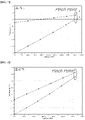
- the second heating medium that is, glycol water, heated through heat exchange with the seawater in the second heat exchanger 320 is supplied as the heat source of the trim heater 130 to prevent generation of the pinch point inside the trim heater 130 (see FIG. 4 ), thereby securing sufficient heat exchange performance while stably heating the natural gas to the final delivery temperature.
- the first heating medium is not condensed in the vaporizer 120 and thus cannot be circulated.
- it is necessary to increase load of the vaporizer 120 while maintaining supply balance between LNG and the first heating medium. This causes difficulty in operation of the liquefied-gas regasification system.
- glycol water is used as the second heating medium for heating the natural gas in the trim heater 130, whereby the regasification system can prevent LNG from entering the vaporizer 120 due to supply unbalance between LNG and the first heating medium in an initial operation stage of the regasification system, thereby enabling stable operation of the regasification system.
- the seawater pump 410, the first heat exchanger 220 and the second heat exchanger 320 are disposed in a machinery space under the deck, and the vaporizer 120 and the trim heater 130 are disposed on an upper deck.
- the seawater pump 410 When the seawater suctioned by the seawater pump 410 disposed under the deck is directly supplied to the vaporizer 120 and the trim heater 130 disposed on the upper deck, that is, upon direct heat exchange between the seawater and LNG, the seawater pump 410 suffers from significant power consumption.
- the first cycle is provided to allow heat exchange between the seawater suctioned by the seawater pump 410 and the first heating medium in the first heat exchanger 220 disposed in the machinery space under the deck such that LNG is gasified in the vaporizer 120 by the first heating medium heated by the seawater
- the second cycle is provided to allow heat exchange between the seawater and the second heating medium in the second heat exchanger 320 disposed in the machinery space under the deck such that natural gas is heated in the trim heater 130 by the second heating medium heated by the seawater, thereby reducing power consumption through reduction in minimum head of the seawater pump 410.
- the overall power consumption is reduced since the circulation amounts thereof are not large, as compared with the circulation amount of the seawater.
- FIG. 2 is a schematic diagram of the liquefied gas regasification system shown in FIG. 1 , illustrating a temperature controller for description of the temperature control method, in which some components of the regasification system are omitted.
- the regasification system further includes a second pressure measurement unit PT2 adapted to measure an inner pressure of the receiver 240 and a second branch-off line RL2 branched upward of the vaporizer 120 from the first heating medium line RL and connected to the receiver 240, in which a second valve RV is provided to the second branch-off line RL2.
- a second pressure measurement unit PT2 adapted to measure an inner pressure of the receiver 240 and a second branch-off line RL2 branched upward of the vaporizer 120 from the first heating medium line RL and connected to the receiver 240, in which a second valve RV is provided to the second branch-off line RL2.
- the regasification system further includes a second pressure controller PIC2 that controls the second valve RV in order to regulate the flow rate of the first heating medium bypassing the vaporizer 120 and supplied to the receiver 240 among the first heating medium supplied from the expander-generator 230 and/or the first heat exchanger 220 to the vaporizer 120 depending upon the pressure measured by the second pressure measurement unit PT2.
- a second pressure controller PIC2 that controls the second valve RV in order to regulate the flow rate of the first heating medium bypassing the vaporizer 120 and supplied to the receiver 240 among the first heating medium supplied from the expander-generator 230 and/or the first heat exchanger 220 to the vaporizer 120 depending upon the pressure measured by the second pressure measurement unit PT2.
- the second valve RV may also be controlled depending upon the temperature of the natural gas measured by a third temperature controller TIC3 that measures the temperature of the natural gas supplied from the vaporizer 120 to the trim heater 130.
- a third temperature controller TIC3 that measures the temperature of the natural gas supplied from the vaporizer 120 to the trim heater 130.
- the second controller LS2 may control the opening degree of the second valve RV based on the flow rate of the first heating medium branched off toward the second branch-off line RL2, in order to maintain the flow rate of the first heating medium branched off towards the second branch-off line RL2, as sent from the second pressure controller PIC2, and to maintain the temperature of the natural gas supplied from the vaporizer 120 to the trim heater 130, as sent from the third temperature controller TIC3.
- the second controller LS2 may include a low selector adapted to control the second valve RV by selecting a smaller value among the opening degrees of the second valve RV for controlling the flow rate of the first heating medium to be branched off towards the second branch-off line RL2, as sent from the second pressure controller PIC2 and the third temperature controller TIC3.
- the second pressure controller PIC2 sends a signal to the second controller LS2 so as to increase the flow rate of the first heating medium, which bypasses the vaporizer 120 to be supplied to the receiver 240, by increasing the opening degree of the second valve RV.
- the third temperature controller TIC3 sends a signal to the second controller LS2 so as to decrease the flow rate of the first heating medium, which bypasses the vaporizer 120, by decreasing the opening degree of the second valve RV.
- the second controller LS2 controls the opening degree of the second valve RV by selecting a smaller value among the opening degrees of the second valve RV, as sent from the second pressure controller PIC2 and the third temperature controller TIC3. That is, the second controller LS2 controls the opening degree of the second valve RV while maintaining the minimum flow rate of the first heating medium to be regulated to bypass the vaporizer 120.
- the regasification system includes a first temperature measurement unit TT1 adapted to measure the temperature of the natural gas supplied from the trim heater 130 to a gas consumer, a first pressure measurement unit PT1 adapted to measure the pressure of the natural gas supplied from the trim heater 130 to the gas consumer, and a first flow rate measurement unit FT1 adapted to measure the flow rate of the natural gas supplied from the trim heater 130 to the gas consumer.
- the regasification system further includes a first temperature controller TIC1 adapted to maintain the temperature of the natural gas supplied from the trim heater 130 to the gas consumer depending upon the temperature measured by the first temperature measurement unit TT1, and a first flow rate controller FIC1 adapted to regulate the flow rate of the natural gas supplied from the trim heater 130 to the gas consumer depending upon the values measured by the first temperature measurement unit TT1, the first pressure measurement unit PT1 and the first flow rate measurement unit FT1.
- a first temperature controller TIC1 adapted to maintain the temperature of the natural gas supplied from the trim heater 130 to the gas consumer depending upon the temperature measured by the first temperature measurement unit TT1
- a first flow rate controller FIC1 adapted to regulate the flow rate of the natural gas supplied from the trim heater 130 to the gas consumer depending upon the values measured by the first temperature measurement unit TT1, the first pressure measurement unit PT1 and the first flow rate measurement unit FT1.
- the regasification system further includes a second temperature measurement unit TT2 adapted to measure the temperature of the second heating medium discharged from the trim heater 130 and a second temperature controller TIC2 adapted to maintain the temperature of the second heating medium discharged from the trim heater 130 depending upon the temperature measured by the second temperature measurement unit TT2.
- the regasification system further includes a first valve LV provided to a liquefied gas line LL along which LNG supplied from the high-pressure pump 110 to the vaporizer 120 flows.
- the first controller LS1 may regulate the opening degree of the first valve LV in response to signals sent from the first temperature controller TIC1, the second temperature controller TIC2, and the first flow rate controller FIC1.
- the first controller LS1 may satisfy a target regasification amount by increasing the opening degree of the first valve LV in response to the signal sent from the first flow rate controller FIC1 so as to increase the flow rate of LNG supplied from the high-pressure pump 110 to the vaporizer 120.
- the first controller LS1 may satisfy a target regasification temperature by decreasing the opening degree of the first valve LV in response to the signal sent from the first temperature controller TIC1 so as to decrease the flow rate of LNG supplied from the high-pressure pump 110 to the vaporizer 120.
- the first controller LS1 may maintain the temperature of the second heating medium at an outlet of the trim heater 130 to be higher than or equal to the minimum temperature by decreasing the opening degree of the first valve LV in response to the signal sent from the second temperature controller TIC so as to decrease the flow rate of LNG supplied from the high-pressure pump 110 to the vaporizer 120.
- the first controller LS1 may include a low selector adapted to control the opening degree of the first valve LV by selecting the lowest value of the first valve LV, that is, the lowest opening degree thereof, among the signals sent from the first flow rate controller FIC1, the first temperature controller TIC1 and the second temperature controller TIC2.
- the regasification system can generate power while reducing fuel consumption for power generation by recovering cold heat discarded in regasification of liquefied gas, and can maintain a delivery temperature, pressure and flow rate of the regasified gas within predetermined ranges even upon reduction in temperature of a heat source supplied to the vaporizer by additionally generating power through recovery of the cold heat of the liquefied gas.
Landscapes
- Engineering & Computer Science (AREA)
- Mechanical Engineering (AREA)
- General Engineering & Computer Science (AREA)
- Chemical & Material Sciences (AREA)
- Combustion & Propulsion (AREA)
- Ocean & Marine Engineering (AREA)
- Filling Or Discharging Of Gas Storage Vessels (AREA)
Applications Claiming Priority (2)
| Application Number | Priority Date | Filing Date | Title |
|---|---|---|---|
| KR1020200014700A KR102271761B1 (ko) | 2020-02-07 | 2020-02-07 | 선박의 액화가스 재기화 시스템 및 방법 |
| PCT/KR2020/018773 WO2021157855A1 (ko) | 2020-02-07 | 2020-12-21 | 선박의 액화가스 재기화 시스템 및 방법 |
Publications (3)
| Publication Number | Publication Date |
|---|---|
| EP4101752A1 true EP4101752A1 (de) | 2022-12-14 |
| EP4101752A4 EP4101752A4 (de) | 2024-03-20 |
| EP4101752B1 EP4101752B1 (de) | 2026-03-18 |
Family
ID=76896740
Family Applications (1)
| Application Number | Title | Priority Date | Filing Date |
|---|---|---|---|
| EP20918026.4A Active EP4101752B1 (de) | 2020-02-07 | 2020-12-21 | System und verfahren zum regasifizieren von verflüssigtem schiffsgas |
Country Status (6)
| Country | Link |
|---|---|
| EP (1) | EP4101752B1 (de) |
| JP (1) | JP7490787B2 (de) |
| KR (2) | KR102271761B1 (de) |
| CN (1) | CN115052809B (de) |
| BR (1) | BR112022015470A2 (de) |
| WO (1) | WO2021157855A1 (de) |
Cited By (1)
| Publication number | Priority date | Publication date | Assignee | Title |
|---|---|---|---|---|
| WO2025183563A1 (en) * | 2024-02-29 | 2025-09-04 | Wärtsilä Gas Solutions Norway AS | A regasification system for liquified gas, a ship, and a method of regasification of liquefied gas |
Families Citing this family (4)
| Publication number | Priority date | Publication date | Assignee | Title |
|---|---|---|---|---|
| KR102536782B1 (ko) * | 2021-08-13 | 2023-05-26 | 한국해양과학기술원 | 액화 수소 기화 시의 부피 팽창에 의한 가압력을 이용한 발전 시스템 |
| CN114909605B (zh) * | 2022-06-08 | 2024-04-19 | 江苏科技大学 | Lng船冷能循环存储及冷能综合利用系统及其工作方法 |
| CN117028825B (zh) * | 2023-08-02 | 2025-10-03 | 北京航天试验技术研究所 | 一种混合储氢系统及方法 |
| JP2025062869A (ja) * | 2023-10-03 | 2025-04-15 | 日本エア・リキード合同会社 | 液化水素源から冷熱を回収する冷熱回収装置およびそれを備える水素供給ステーション |
Family Cites Families (19)
| Publication number | Priority date | Publication date | Assignee | Title |
|---|---|---|---|---|
| US6564579B1 (en) * | 2002-05-13 | 2003-05-20 | Black & Veatch Pritchard Inc. | Method for vaporizing and recovery of natural gas liquids from liquefied natural gas |
| CA2615850C (en) * | 2005-07-18 | 2011-01-25 | Fluor Technologies Corporation | Configurations and methods for power generation in lng regasification terminals |
| US20070271932A1 (en) * | 2006-05-26 | 2007-11-29 | Chevron U.S.A. Inc. | Method for vaporizing and heating a cryogenic fluid |
| CN104981646B (zh) * | 2012-08-24 | 2017-09-08 | 奥斯康普控股公司 | 虚拟气态燃料管道 |
| KR102082362B1 (ko) * | 2013-09-27 | 2020-02-27 | 익셀러레이트 에너지 리미티드 파트너쉽 | 극저온 저장 선박에 있는 보일 오프 가스 속의 잠열의 수집, 이용, 배출을 위한 장치, 시스템, 방법 |
| CN104315339B (zh) * | 2014-10-27 | 2016-02-24 | 中国海洋石油总公司 | 应用于海上浮式lng再气化装置的lng阶梯式再气化系统及再气化方法 |
| KR101904412B1 (ko) * | 2015-12-18 | 2018-11-30 | 현대중공업 주식회사 | 가스 재기화 시스템 |
| US10823335B2 (en) * | 2016-02-01 | 2020-11-03 | Hyundai Heavy Industries Co., Ltd. | Ship including gas re-vaporizing system |
| KR101831522B1 (ko) * | 2016-02-01 | 2018-02-22 | 현대중공업 주식회사 | 가스 재기화 시스템을 구비하는 선박 |
| JP6689997B2 (ja) * | 2016-04-07 | 2020-04-28 | コリア シップビルディング アンド オフショア エンジニアリング カンパニー リミテッド | ガス再気化システムを備える船舶 |
| KR101945596B1 (ko) * | 2016-09-30 | 2019-02-07 | 현대중공업 주식회사 | 가스 재기화 시스템 및 이를 포함하는 선박 |
| KR20180042938A (ko) * | 2016-10-19 | 2018-04-27 | 대우조선해양 주식회사 | 액화가스 재기화 시스템 및 운전 방법 |
| KR102286693B1 (ko) * | 2016-11-28 | 2021-08-09 | 한국조선해양 주식회사 | 가스 재기화 시스템 및 이를 포함하는 선박 |
| JP6779146B2 (ja) * | 2017-01-27 | 2020-11-04 | 株式会社神戸製鋼所 | 天然ガス焚きコンバインドサイクル発電システム及び天然ガス焚きコンバインドサイクル発電方法 |
| KR20180002489U (ko) * | 2017-02-09 | 2018-08-20 | 대우조선해양 주식회사 | 해상 구조물의 lng 재기화 시스템 |
| KR102285467B1 (ko) * | 2017-05-11 | 2021-08-05 | 삼성중공업 주식회사 | 액화가스 재기화 시스템 |
| KR102258009B1 (ko) * | 2017-07-26 | 2021-05-28 | 현대중공업 주식회사 | 가스 재기화 시스템 및 이를 포함하는 선박 |
| KR20190068875A (ko) * | 2017-12-11 | 2019-06-19 | 대우조선해양 주식회사 | 선박의 액화가스 재기화 시스템 및 방법 |
| KR102442558B1 (ko) * | 2018-05-30 | 2022-09-13 | 대우조선해양 주식회사 | 액화천연가스 재기화 시스템 및 방법 |
-
2020
- 2020-02-07 KR KR1020200014700A patent/KR102271761B1/ko active Active
- 2020-12-21 CN CN202080095821.1A patent/CN115052809B/zh active Active
- 2020-12-21 BR BR112022015470A patent/BR112022015470A2/pt unknown
- 2020-12-21 JP JP2022547099A patent/JP7490787B2/ja active Active
- 2020-12-21 WO PCT/KR2020/018773 patent/WO2021157855A1/ko not_active Ceased
- 2020-12-21 EP EP20918026.4A patent/EP4101752B1/de active Active
-
2021
- 2021-05-24 KR KR1020210066250A patent/KR102393101B1/ko active Active
Cited By (1)
| Publication number | Priority date | Publication date | Assignee | Title |
|---|---|---|---|---|
| WO2025183563A1 (en) * | 2024-02-29 | 2025-09-04 | Wärtsilä Gas Solutions Norway AS | A regasification system for liquified gas, a ship, and a method of regasification of liquefied gas |
Also Published As
| Publication number | Publication date |
|---|---|
| WO2021157855A1 (ko) | 2021-08-12 |
| KR20210101167A (ko) | 2021-08-18 |
| CN115052809A (zh) | 2022-09-13 |
| EP4101752A4 (de) | 2024-03-20 |
| BR112022015470A2 (pt) | 2022-10-04 |
| KR102393101B1 (ko) | 2022-05-02 |
| KR102271761B1 (ko) | 2021-07-02 |
| JP2023512314A (ja) | 2023-03-24 |
| EP4101752B1 (de) | 2026-03-18 |
| JP7490787B2 (ja) | 2024-05-27 |
| CN115052809B (zh) | 2024-06-04 |
Similar Documents
| Publication | Publication Date | Title |
|---|---|---|
| EP4101752B1 (de) | System und verfahren zum regasifizieren von verflüssigtem schiffsgas | |
| KR102082362B1 (ko) | 극저온 저장 선박에 있는 보일 오프 가스 속의 잠열의 수집, 이용, 배출을 위한 장치, 시스템, 방법 | |
| EP3521155A1 (de) | Vorrichtung und verfahren zur wiederverflüssigung von abdampf eines schiffes | |
| CN107110427A (zh) | 用于冷却液化气的装置和方法 | |
| CN108883817A (zh) | 船的蒸发气体再液化设备及方法 | |
| US20200393196A1 (en) | Device and method for processing boil-off gas in liquefied gas regasification system | |
| KR20200005270A (ko) | 수소 저장탱크가 구비된 해상 부유구조물 | |
| KR102376277B1 (ko) | 선박의 증발가스 재액화 시스템 및 그 운전방법 | |
| KR102911900B1 (ko) | 액화가스 재기화 시스템의 쿨다운 방법 | |
| JP2023529204A (ja) | 液化ガス運搬船の燃料供給システム及び燃料供給方法 | |
| KR102880328B1 (ko) | 선박의 액화가스 재기화 방법 | |
| JP7727840B2 (ja) | 船舶用再液化システムの冷媒充填システム | |
| KR102726450B1 (ko) | 액화가스 재기화 선박의 액화가스 재기화 시스템 | |
| EP4230513A1 (de) | Verfahren und system zur wiedervergasung von flüssiggas eines schiffes | |
| KR102647308B1 (ko) | 재기화 선박의 재기화 시스템 및 방법 | |
| KR102845046B1 (ko) | 선박의 액화가스 재기화 방법 및 시스템 | |
| KR20210101348A (ko) | 액화가스 재기화 선박의 액화가스 재기화 시스템 | |
| KR20210100868A (ko) | 액화가스 재기화 선박의 액화가스 재기화 시스템 및 방법 | |
| KR102889695B1 (ko) | 액화가스 재기화 시스템 및 이를 구비하는 선박 | |
| KR102707029B1 (ko) | 선박용 재액화 시스템의 냉매사이클 제어 시스템 및 제어 방법 | |
| JP7675289B2 (ja) | 船舶用再液化システムの微少漏洩検知システム | |
| KR102408227B1 (ko) | 선박의 액화가스 재기화 시스템 및 방법 | |
| KR102821198B1 (ko) | 선박의 액화가스 재기화 방법 및 시스템 | |
| KR102905329B1 (ko) | 액화가스 처리 시스템 및 이를 포함하는 선박 | |
| RU2786300C2 (ru) | Устройство получения газа в газообразной форме из сжиженного газа |
Legal Events
| Date | Code | Title | Description |
|---|---|---|---|
| STAA | Information on the status of an ep patent application or granted ep patent |
Free format text: STATUS: THE INTERNATIONAL PUBLICATION HAS BEEN MADE |
|
| PUAI | Public reference made under article 153(3) epc to a published international application that has entered the european phase |
Free format text: ORIGINAL CODE: 0009012 |
|
| STAA | Information on the status of an ep patent application or granted ep patent |
Free format text: STATUS: REQUEST FOR EXAMINATION WAS MADE |
|
| 17P | Request for examination filed |
Effective date: 20220804 |
|
| AK | Designated contracting states |
Kind code of ref document: A1 Designated state(s): AL AT BE BG CH CY CZ DE DK EE ES FI FR GB GR HR HU IE IS IT LI LT LU LV MC MK MT NL NO PL PT RO RS SE SI SK SM TR |
|
| DAV | Request for validation of the european patent (deleted) | ||
| DAX | Request for extension of the european patent (deleted) | ||
| RAP3 | Party data changed (applicant data changed or rights of an application transferred) |
Owner name: HANWHA OCEAN CO., LTD. |
|
| A4 | Supplementary search report drawn up and despatched |
Effective date: 20240216 |
|
| RIC1 | Information provided on ipc code assigned before grant |
Ipc: F17C 13/02 20060101ALI20240212BHEP Ipc: F17C 13/04 20060101ALI20240212BHEP Ipc: F17C 9/00 20060101ALI20240212BHEP Ipc: B63B 13/00 20060101ALI20240212BHEP Ipc: B63J 3/04 20060101ALI20240212BHEP Ipc: B63B 25/16 20060101AFI20240212BHEP |
|
| GRAP | Despatch of communication of intention to grant a patent |
Free format text: ORIGINAL CODE: EPIDOSNIGR1 |
|
| STAA | Information on the status of an ep patent application or granted ep patent |
Free format text: STATUS: GRANT OF PATENT IS INTENDED |
|
| INTG | Intention to grant announced |
Effective date: 20251208 |
|
| GRAS | Grant fee paid |
Free format text: ORIGINAL CODE: EPIDOSNIGR3 |
|
| GRAA | (expected) grant |
Free format text: ORIGINAL CODE: 0009210 |
|
| STAA | Information on the status of an ep patent application or granted ep patent |
Free format text: STATUS: THE PATENT HAS BEEN GRANTED |
|
| AK | Designated contracting states |
Kind code of ref document: B1 Designated state(s): AL AT BE BG CH CY CZ DE DK EE ES FI FR GB GR HR HU IE IS IT LI LT LU LV MC MK MT NL NO PL PT RO RS SE SI SK SM TR |
|
| REG | Reference to a national code |
Ref country code: CH Ref legal event code: F10 Free format text: ST27 STATUS EVENT CODE: U-0-0-F10-F00 (AS PROVIDED BY THE NATIONAL OFFICE) Effective date: 20260318 Ref country code: GB Ref legal event code: FG4D |
|
| REG | Reference to a national code |
Ref country code: IE Ref legal event code: FG4D |
|
| REG | Reference to a national code |
Ref country code: DE Ref legal event code: R096 Ref document number: 602020069023 Country of ref document: DE |