EP4101684B1 - Batteriemodul für ein kraftfahrzeug - Google Patents
Batteriemodul für ein kraftfahrzeug Download PDFInfo
- Publication number
- EP4101684B1 EP4101684B1 EP22177747.7A EP22177747A EP4101684B1 EP 4101684 B1 EP4101684 B1 EP 4101684B1 EP 22177747 A EP22177747 A EP 22177747A EP 4101684 B1 EP4101684 B1 EP 4101684B1
- Authority
- EP
- European Patent Office
- Prior art keywords
- profile
- battery module
- cooling
- cooling profile
- module according
- Prior art date
- Legal status (The legal status is an assumption and is not a legal conclusion. Google has not performed a legal analysis and makes no representation as to the accuracy of the status listed.)
- Active
Links
Images

Classifications
-
- H—ELECTRICITY
- H01—ELECTRIC ELEMENTS
- H01M—PROCESSES OR MEANS, e.g. BATTERIES, FOR THE DIRECT CONVERSION OF CHEMICAL ENERGY INTO ELECTRICAL ENERGY
- H01M50/00—Constructional details or processes of manufacture of the non-active parts of electrochemical cells other than fuel cells, e.g. hybrid cells
- H01M50/20—Mountings; Secondary casings or frames; Racks, modules or packs; Suspension devices; Shock absorbers; Transport or carrying devices; Holders
- H01M50/204—Racks, modules or packs for multiple batteries or multiple cells
- H01M50/207—Racks, modules or packs for multiple batteries or multiple cells characterised by their shape
- H01M50/213—Racks, modules or packs for multiple batteries or multiple cells characterised by their shape adapted for cells having curved cross-section, e.g. round or elliptic
-
- B—PERFORMING OPERATIONS; TRANSPORTING
- B60—VEHICLES IN GENERAL
- B60L—PROPULSION OF ELECTRICALLY-PROPELLED VEHICLES; SUPPLYING ELECTRIC POWER FOR AUXILIARY EQUIPMENT OF ELECTRICALLY-PROPELLED VEHICLES; ELECTRODYNAMIC BRAKE SYSTEMS FOR VEHICLES IN GENERAL; MAGNETIC SUSPENSION OR LEVITATION FOR VEHICLES; MONITORING OPERATING VARIABLES OF ELECTRICALLY-PROPELLED VEHICLES; ELECTRIC SAFETY DEVICES FOR ELECTRICALLY-PROPELLED VEHICLES
- B60L50/00—Electric propulsion with power supplied within the vehicle
- B60L50/50—Electric propulsion with power supplied within the vehicle using propulsion power supplied by batteries or fuel cells
- B60L50/60—Electric propulsion with power supplied within the vehicle using propulsion power supplied by batteries or fuel cells using power supplied by batteries
- B60L50/64—Constructional details of batteries specially adapted for electric vehicles
-
- H—ELECTRICITY
- H01—ELECTRIC ELEMENTS
- H01M—PROCESSES OR MEANS, e.g. BATTERIES, FOR THE DIRECT CONVERSION OF CHEMICAL ENERGY INTO ELECTRICAL ENERGY
- H01M10/00—Secondary cells; Manufacture thereof
- H01M10/60—Heating or cooling; Temperature control
- H01M10/62—Heating or cooling; Temperature control specially adapted for specific applications
- H01M10/625—Vehicles
-
- H—ELECTRICITY
- H01—ELECTRIC ELEMENTS
- H01M—PROCESSES OR MEANS, e.g. BATTERIES, FOR THE DIRECT CONVERSION OF CHEMICAL ENERGY INTO ELECTRICAL ENERGY
- H01M10/00—Secondary cells; Manufacture thereof
- H01M10/60—Heating or cooling; Temperature control
- H01M10/65—Means for temperature control structurally associated with the cells
- H01M10/655—Solid structures for heat exchange or heat conduction
- H01M10/6556—Solid parts with flow channel passages or pipes for heat exchange
-
- H—ELECTRICITY
- H01—ELECTRIC ELEMENTS
- H01M—PROCESSES OR MEANS, e.g. BATTERIES, FOR THE DIRECT CONVERSION OF CHEMICAL ENERGY INTO ELECTRICAL ENERGY
- H01M10/00—Secondary cells; Manufacture thereof
- H01M10/60—Heating or cooling; Temperature control
- H01M10/65—Means for temperature control structurally associated with the cells
- H01M10/656—Means for temperature control structurally associated with the cells characterised by the type of heat-exchange fluid
- H01M10/6567—Liquids
-
- H—ELECTRICITY
- H01—ELECTRIC ELEMENTS
- H01M—PROCESSES OR MEANS, e.g. BATTERIES, FOR THE DIRECT CONVERSION OF CHEMICAL ENERGY INTO ELECTRICAL ENERGY
- H01M50/00—Constructional details or processes of manufacture of the non-active parts of electrochemical cells other than fuel cells, e.g. hybrid cells
- H01M50/20—Mountings; Secondary casings or frames; Racks, modules or packs; Suspension devices; Shock absorbers; Transport or carrying devices; Holders
- H01M50/218—Mountings; Secondary casings or frames; Racks, modules or packs; Suspension devices; Shock absorbers; Transport or carrying devices; Holders characterised by the material
- H01M50/22—Mountings; Secondary casings or frames; Racks, modules or packs; Suspension devices; Shock absorbers; Transport or carrying devices; Holders characterised by the material of the casings or racks
- H01M50/222—Inorganic material
- H01M50/224—Metals
-
- H—ELECTRICITY
- H01—ELECTRIC ELEMENTS
- H01M—PROCESSES OR MEANS, e.g. BATTERIES, FOR THE DIRECT CONVERSION OF CHEMICAL ENERGY INTO ELECTRICAL ENERGY
- H01M2220/00—Batteries for particular applications
- H01M2220/20—Batteries in motive systems, e.g. vehicle, ship, plane
-
- Y—GENERAL TAGGING OF NEW TECHNOLOGICAL DEVELOPMENTS; GENERAL TAGGING OF CROSS-SECTIONAL TECHNOLOGIES SPANNING OVER SEVERAL SECTIONS OF THE IPC; TECHNICAL SUBJECTS COVERED BY FORMER USPC CROSS-REFERENCE ART COLLECTIONS [XRACs] AND DIGESTS
- Y02—TECHNOLOGIES OR APPLICATIONS FOR MITIGATION OR ADAPTATION AGAINST CLIMATE CHANGE
- Y02E—REDUCTION OF GREENHOUSE GAS [GHG] EMISSIONS, RELATED TO ENERGY GENERATION, TRANSMISSION OR DISTRIBUTION
- Y02E60/00—Enabling technologies; Technologies with a potential or indirect contribution to GHG emissions mitigation
- Y02E60/10—Energy storage using batteries
-
- Y—GENERAL TAGGING OF NEW TECHNOLOGICAL DEVELOPMENTS; GENERAL TAGGING OF CROSS-SECTIONAL TECHNOLOGIES SPANNING OVER SEVERAL SECTIONS OF THE IPC; TECHNICAL SUBJECTS COVERED BY FORMER USPC CROSS-REFERENCE ART COLLECTIONS [XRACs] AND DIGESTS
- Y02—TECHNOLOGIES OR APPLICATIONS FOR MITIGATION OR ADAPTATION AGAINST CLIMATE CHANGE
- Y02T—CLIMATE CHANGE MITIGATION TECHNOLOGIES RELATED TO TRANSPORTATION
- Y02T10/00—Road transport of goods or passengers
- Y02T10/60—Other road transportation technologies with climate change mitigation effect
- Y02T10/70—Energy storage systems for electromobility, e.g. batteries
Definitions
- the invention relates to a battery module for a motor vehicle.
- a battery module includes a battery compartment for accommodating several battery cells. This battery room is surrounded by a closed frame formed from side wall profiles and closed at the bottom by a floor. When these battery cells are charged and discharged, heat is generated that must be dissipated from the battery modules.
- the battery modules include cooling elements.
- profiles that are used for a base of a battery module must have sufficient strength. If a battery base, for example for a motor vehicle, is to be made from cooling profiles made of a 3000 alloy, either correspondingly massive profile dimensions and wall thicknesses must be provided, or an additional holding structure designed for this purpose must be provided to meet the mechanical requirements, for example made from further extruded profiles or from sheet metal layers .
- the object of the present invention is to provide a battery module with very good cooling in the base area, the base being structurally simple and easy to manufacture with sufficient strength.
- the new battery module for a motor vehicle includes a battery compartment to accommodate several battery cells.
- This battery room is surrounded by a closed frame formed from side wall profiles and closed at the bottom by a floor.
- the base consists of a flat cooling profile made of an aluminum alloy with the main alloy elements magnesium and silicon.
- This cooling profile consists of at least one extruded multi-chamber hollow profile with several, next to each other arranged chambers, which are separated from each other by separating webs.
- the cooling profile is very delicate and has a large number of chambers for the flow of the cooling medium.
- the cooling profile shows good heat transfer properties. Small wall thicknesses of the cooling profile promote the heat transfer from the battery cells to the cooling medium, which flows through the chambers of the cooling profile. Since the width of the cooling profile is at least 40 times the height of the cooling profile, the efficiency of heat transfer is high.
- an extruded multi-chamber hollow profile made of a hardenable aluminum alloy is suitable for a cooling profile as the bottom of a battery module.
- a hardenable Al-Mg-Si aluminum alloy namely a 6XXX aluminum alloy, is used to produce the multi-chamber hollow profile.
- the strength is increased through a suitable heat treatment process following the extrusion of the semi-finished product, so that a profile with high mechanical strength is obtained.
- the multi-chamber hollow profiles consist of an Al-Mg-Si alloy with a magnesium content of a maximum of 0.9% by weight and a copper content of a maximum of 0.1% by weight.
- the limitation of magnesium is particularly provided if a brazing process is used as a connection process for the cooling profile with other components, since magnesium reacts with the flux.
- the extruded cooling profile which consists of one or more flat multi-chamber hollow profiles, alone forms the bottom of the battery module. Additional holding structures, reinforcing plates or sandwich structures are not necessary.
- a cooling medium flows through the cooling profile. It is envisaged that the cooling medium flows in through an inlet at a first end of the cooling profile and through a certain number of chambers of the cooling profile first chambers, flows, for example, through half of the chambers of the cooling profile. At the other end of the cooling profile, the flow direction of the cooling medium is changed and after the flow reversal, the flow flows through second chambers of the cooling profile until the cooling medium can flow out of an outlet at the first end of the cooling profile.
- the chambers are separated from one another in a known manner by separating webs running in the longitudinal direction of the cooling profile.
- a separating web namely the one between a first chamber and a second chamber, has a greater width than the other separating webs, which are each between the first chambers and which are each between the second chambers.
- the wall thickness of the narrow separators and also the wall thickness of the profile wall are 0.8 mm to 2 mm. In a preferred embodiment, this wall thickness is between 1.0 mm and 1.5 mm.
- the width of the wider divider is at least 5 times the width of the narrow dividers.
- the wall thickness of the outer walls running parallel to the separating webs is also thicker than the other profile wall of the cooling profile.
- a cooling medium flows through the cooling profile.
- This can be, for example, a water-glycol mixture, a thermal oil or another known cooling medium.
- recesses are provided on the cooling profile at one end of the cooling profile.
- the cooling profile has been machined at one end.
- the narrow dividers at the ends were shortened and the profile wall above the narrow dividers was also removed in this area.
- the wider divider remains. The machining is made easier by the fact that, due to the wider separating web in the middle of the profile and the two wider outer walls, tight tolerances do not have to be adhered to during machining, namely the formation of the recesses.
- cover elements are made of stainless steel, aluminum or plastic. They are molded parts, e.g. deep-drawn sheet metal parts or injection-molded plastic parts. In a special embodiment, cover elements are formed integrally with an inlet port or an outlet port. These cover elements are connected to the cooling profile, for example by gluing. If the cover elements are made of aluminum, for example, soldering or welding can also be used as connection methods, such as a brazing process, a laser welding process or an electron beam welding process.
- the new battery module provides a module with efficient cooling in the base area, with the base having a simple structure, namely consisting only of the cooling profile, which comprises a multi-chamber hollow profile or several multi-chamber hollow profiles connected to one another on the longitudinal edge.
- a multi-chamber hollow profile can be easily produced by extrusion, consists of a delicately processed 6XXX aluminum alloy and, through subsequent heat treatment, is given the necessary strength for use as the base of the battery module.
- the high mechanical strength and bending rigidity is further supported by the solid, wider divider and the wide longitudinal edges.
- the cooling profile shows very good cooling due to the large number of chambers for the flow of the cooling medium, due to the small wall thicknesses of the cooling profile and the shape of the profile with a width of 40 times the width of the cooling profile compared to the height of the cooling profile.
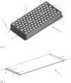
- the Fig. 1 shows an exemplary embodiment of the battery module 10 according to the invention for a motor vehicle. It has a battery compartment to accommodate several battery cells 11, for example cylindrical battery cells 11 as in this example, but also for prismatic cells or pouch cells.
- the battery compartment is surrounded by a closed frame 12 formed from side wall profiles and closed at the bottom by a floor.
- the floor here is formed by an extruded multi-chamber profile made of an aluminum alloy. This multi-chamber profile serves as a cooling profile 13.
- the frame 12 can also consist of extruded aluminum profiles that are connected to the cooling profile 13. The connection can be made, for example, by gluing, welding or screwing. In addition, there can be central bars which increase the bending stiffness of the floor.
- the base from the extruded cooling profile 13 with the covers 30, 31, 32 is separately in Fig. 2 shown.
- the cooling profile 13 exists in this Example of a multi-chamber hollow profile made of an Al-Mg-Si alloy with the following composition: Mg 0.42% Si 0.43% Fe 0.20% Cu 0.01% Mn 0.01% Cr 0.01% Zn 0.01% Ti 0.02% Rest aluminum.
- the ratio between profile height and profile width is approximately 1:68, namely with a profile height of 4.5 mm and a width of 306 mm.
- several extruded multi-chamber hollow profiles are joined together along the sides. This makes it possible, for example, to achieve a width that corresponds to the vehicle width.
- the multi-chamber hollow profiles are preferably joined using a welding process.
- the welding process is, for example, a laser or a friction stir welding process.
- wide, solid longitudinal edges on the extruded multi-chamber hollow profile are an advantage.
- the longitudinal edges on the cooling profile 13, as shown in the Figs. 4 and 5 are shown, for example, have a width of 10 mm. Such longitudinal edges can also be used for screwing to the frame 12 or for other connection methods.
- the cooling profile 13 made of the flat multi-chamber hollow profile has several chambers 17, 17 'arranged next to one another, which are separated from one another by separating webs 18, 19.
- the one separating web 19, which runs along the central axis here, is wider. It separates the area with the first chamber 17 from the area with the second chambers 17 '.
- the separators 18 and the profile wall 16 of the cooling profile 13 have a wall thickness of 1 mm.
- the wider one Divider 19 is 10 mm wide. The wide separating web 19 facilitates the clean separation of the different flow areas during machining to create the recesses on the cooling profile 13.
- a cooling medium flows through the cooling profile 13.
- the cooling media stream 20 is in Fig. 3 indicated.
- the cooling medium is fed in through an inlet 21 and then flows through the first chambers 17.
- the flow direction changes and the cooling medium flows back through the second chambers 17 'of the cooling profile 13 to an outlet 22.
- Fig. 4 shows an end 14 of the multi-chamber hollow profile for the cooling profile 13, ie on the inlet and outlet side. All narrow separating webs 18 have been shortened and the upper profile wall 16 has been shortened above the chambers 17, 17 'together with the separating webs 18. Only the divider 19 remains unchanged. This results in two recesses at this end 14, one in the area of the inlet 21, in front of the chambers 17 and one in the area of the outlet in front of the chambers 17 '. These two recesses are covered by the cover elements 30 and 31. The cover elements 30, 31, in this case formed aluminum sheets, are connected to the cooling profile 13, see Fig. 2 .
- a cover element 32 is also mounted on the opposite end 15 of the cooling profile 13. This also limits a recess, which in Fig. 5 is shown. This recess connects all chambers of the multi-chamber hollow profile.
Landscapes
- Engineering & Computer Science (AREA)
- Chemical & Material Sciences (AREA)
- Chemical Kinetics & Catalysis (AREA)
- Electrochemistry (AREA)
- General Chemical & Material Sciences (AREA)
- Manufacturing & Machinery (AREA)
- Inorganic Chemistry (AREA)
- Life Sciences & Earth Sciences (AREA)
- Sustainable Development (AREA)
- Sustainable Energy (AREA)
- Power Engineering (AREA)
- Transportation (AREA)
- Mechanical Engineering (AREA)
- Secondary Cells (AREA)
- Battery Mounting, Suspending (AREA)
Description
- Die Erfindung betrifft ein Batteriemodul für ein Kraftfahrzeug. Ein solches Batteriemodul umfasst einen Batterieraum zur Aufnahme mehrerer Batteriezellen. Dieser Batterieraum ist von einem aus Seitenwandprofilen gebildeten geschlossenen Rahmen umgeben und nach unten von einem Boden verschlossen. Beim Laden und Entladen dieser Batteriezellen entsteht Wärme, die aus den Batteriemodulen abgeführt werden muss. Hierzu umfassen die Batteriemodule Kühlelemente.
- Es ist bekannt, Wärmetauscher für Kraftfahrzeuge aus Aluminiumprofilen durch Strangpressen herzustellen. Hierzu werden üblicherweise Legierungen der Serie 3000, also Aluminiumlegierungen mit dem Hauptlegierungselement Mangan eingesetzt. Diese Legierungen weisen neben einer guten Korrosionsresistenz eine sehr gute Umformbarkeit auf, wodurch sich Profile mit einer sehr geringen Wandstärke, mit filigranen Profilquerschnitten und mit einer Vielzahl von Hohlkammern erzielen lassen und dies bei einem sehr guten Höhe-zu-Breite-Verhältnis, was eine hohe Wärmeabführung ermöglicht. Diese Legierungen sind jedoch weich und weisen eine geringe mechanische Festigkeit auf. Die mechanischen Eigenschaften eines stranggepressten Profils aus einer solchen nicht aushärtbaren Legierung können auch nicht durch eine geeignete nachfolgende Wärmebehandlung verbessert werden. Profile, die für einen Boden eines Batteriemoduls eingesetzt werden, müssen jedoch eine ausreichende Festigkeit besitzen. Soll ein Batterieboden, beispielsweise für ein Kraftfahrzeug, aus Kühlprofilen aus einer 3000-Legierung hergestellt werden, sind entweder entsprechend massive Profilabmessungen und Wandstärken vorzusehen, oder zur Erfüllung der mechanischen Anforderungen muss eine dafür ausgelegte zusätzliche Haltestruktur vorgesehen werden, beispielsweise aus weiteren Strangpressprofilen oder aus Blechlagen.
- Bei einer bekannten Ausführung gemäß
DE 10 2017 125 004 A1 wird ein stranggepresstes Hohlprofil aus dem Aluminiummaterial gezeigt, welches breite massive Längsrändern zur Verbindung miteinander oder mit einem Rahmen besitzt. Diese Hohlprofile können auch im Bereich des Bodens eingesetzt werden. Bei einem weiteren bekannten DokumentDE 10 2015 111 749 A1 werden Hohlprofile als Kühlelemente verwendet und bilden einen Teil einer Sandwich-Konstruktion. - Es ist aus dem Dokument
EP 3 553 876 B1 auch bekannt, den Boden des Batteriemoduls allein aus einem stranggepressten Aluminiumprofil zu bilden, welches relativ massiv ausgebildet ist. Um mehrere Kammern für das Kühlmedium zu bilden, sind zusätzliche Separatoren zur Bildung von Kühlkammern eingesetzt. Für den Einlass und Auslass des Kühlmediums wird das Profil endseitig mit Kühlmediumverteilern verbunden. Das Herstellungsverfahren ist aufwendig. Das Aluminiumprofil ist relativ massiv ausgebildet. Hier wird eine Verbesserung angestrebt. - Aufgabe der vorliegenden Erfindung ist es, ein Batteriemodul mit einer sehr guten Kühlung im Bodenbereich zur Verfügung zu stellen, wobei der Boden bei ausreichender Festigkeit konstruktiv einfach aufgebaut und auf einfache Weise herstellbar ist.
- Diese Aufgabe wird mit einem Batteriemodul mit den Merkmalen des Anspruchs 1 erfüllt. Besonders vorteilhafte Ausführungen beschreiben die Unteransprüche.
- Das neue Batteriemodul für ein Kraftfahrzeug umfasst einen Batterieraum zur Aufnahme mehrerer Batteriezellen. Dieser Batterieraum ist von einem aus Seitenwandprofilen gebildeten geschlossenen Rahmen umgeben und nach unten von einem Boden verschlossen. Der Boden besteht aus einem flachen Kühlprofil aus einer Aluminiumlegierung mit den Hauptlegierungselementen Magnesium und Silizium. Dieses Kühlprofil besteht aus mindestens einem stranggepressten Mehrkammerhohlprofil mit mehreren, nebeneinander angeordneten Kammern, welche durch Trennstege voneinander getrennt sind. Das Kühlprofil ist sehr filigran ausgebildet und hat eine hohe Anzahl von Kammern für den Durchfluss des Kühlmediums. Das Kühlprofil zeigt gute Wärmeübergangseigenschaften. So begünstigen geringe Wandstärken des Kühlprofils den Wärmeübergang von den Batteriezellen zum Kühlmedium, welches durch die Kammern des Kühlprofils fließt. Da die Breite des Kühlprofils mindestens dem 40-fachen der Höhe des Kühlprofils entspricht, ist die Effizienz des Wärmeübergangs hoch.
- Es hat sich gezeigt, dass ein stranggepresstes Mehrkammerhohlprofil aus einer aushärtbaren Aluminiumlegierung, mit welcher sich solche filigranen Profile erzeugen und die guten Wärmeübergangseigenschaften erzielen lassen, für ein Kühlprofil als Boden eines Batteriemoduls geeignet ist. Zur Herstellung des Mehrkammerhohlprofils wird eine aushärtbare Al-Mg-Si-Aluminiumlegierung, nämlich eine 6XXX-Aluminiumlegierung, verwendet. Die Festigkeit wird durch einen geeigneten Wärmebehandlungsprozess im Anschluss an das Strangpressen des Halbzeuges gesteigert, so dass ein Profil mit hoher mechanischer Belastbarkeit erhalten wird. Bei einer bevorzugten Ausführung bestehen die Mehrkammerhohlprofile aus einer Al-Mg-Si-Legierungen mit einem Magnesiumanteil von maximal 0,9 Gew.-% und einem Kupferanteil von maximal 0,1 Gew%. Die Limitierung von Magnesium wird insbesondere dann vorgesehen, wenn ein Hartlötverfahren als Verbindungsverfahren des Kühlprofils mit weiteren Komponenten vorgesehen wird, da Magnesium mit dem Flussmittel reagiert.
- Vorteilhaft ist, dass das stranggepresste Kühlprofil, welches aus einem oder mehreren flachen Mehrkammerhohlprofilen besteht, allein den Boden des Batteriemoduls bildet. Zusätzliche Haltekonstruktionen, Verstärkungsbleche oder Sandwichkonstruktionen sind nicht notwendig.
- Das Kühlprofil wird von einem Kühlmedium durchströmt. Es ist vorgesehen, dass das Kühlmedium an einem ersten Ende des Kühlprofils durch einen Einlass einströmt und durch eine bestimmte Anzahl von Kammern des Kühlprofils, den ersten Kammern, fließt, beispielsweise durch die Hälfte der Kammern des Kühlprofils. Am anderen Ende des Kühlprofils wird die Strömungsrichtung des Kühlmediums geändert und nach der Strömungsumkehr werden zweite Kammern des Kühlprofils durchströmt bis das Kühlmedium am ersten Ende des Kühlprofils aus einem Auslass ausfließen kann. Die Kammern sind in bekannter Weise durch in Längsrichtung des Kühlprofils verlaufende Trennstege voneinander abgetrennt. Hierbei besitzt ein Trennsteg, nämlich der zwischen einer ersten Kammer und einer zweiten Kammer, eine größere Breite als die anderen Trennstege, welche jeweils zwischen den ersten Kammern und welche jeweils zwischen den zweiten Kammern vorhanden sind. So betragen die Wanddicke der schmalen Trennstege und ebenso die Wanddicke der Profilwand 0,8 mm bis 2 mm. Bei einer bevorzugten Ausführungsform liegt diese Wanddicke zwischen 1,0 mm und 1,5 mm. Die Breite des breiteren Trennstegs entspricht wenigstens dem 5-fachen der Breite der schmalen Trennstege.
- Darüber hinaus ist bei einer vorteilhaften Ausführung auch die Wanddicke der parallel zu den Trennstegen verlaufenden Außenwände dicker ausgebildet als die sonstige Profilwand des Kühlprofils.
- Wie beschrieben durchströmt ein Kühlmedium das Kühlprofil. Dies kann beispielsweise ein Wasser-Glykol-Gemisch, ein Thermoöl oder ein anderes bekanntes Kühlmedium sein. Zum Zu- und Ableiten des Kühlmediums werden an einem Ende des Kühlprofils Ausnehmungen am Kühlprofil vorgesehen. Hierzu ist das Kühlprofil an diesem einen Ende spanend bearbeitet worden. Es wurden die schmalen Trennstege endseitige gekürzt und in diesem Bereich auch die oberhalb der schmalen Trennstege vorhandene Profilwand entfernt. Der breitere Trennsteg bleibt jedoch erhalten. Die spanende Bearbeitung wird dadurch erleichtert, dass aufgrund des breiteren Trennstegs in der Mitte des Profils und der beiden breiteren Außenwände keine engen Toleranzen bei der Bearbeitung, nämlich der Ausbildung der Ausnehmungen, einzuhalten sind. Diese beispielsweise durch Fräsen erhaltenen Ausnehmungen an einem Ende des Kühlprofils werden von zusätzlichen Abdeckelementen, welche beispielsweise auch Anschlussflansche aufweisen, abgedeckt. Um eine Zirkulation des Kühlmediums zu gewährleisten, ist auch am entgegengesetzte Ende des Kühlprofils eine Ausnehmung vorhanden, die durch ein weiteres Abdeckungselement verschlossen wird, so dass der vorbeschrieben Kühlmediumstrom möglich wird. Diese Ausnehmung am anderen Ende des Kühlprofils wird durch eine endseitige Verkürzung aller Trennstege gebildet. Auch in diesem Bereich ist die oberhalb der Trennstege vorhandene Profilwand entfernt.
- Die Abdeckelemente bestehen aus Edelstahl, Aluminium oder Kunststoff. Sie sind geformte Teile, z.B. tiefgezogene Blechteile oder spritzgegossene Kunststoffteile. Bei einer besonderen Ausführungsform sind Abdeckelemente integral mit einem Einlassstutzen bzw. einem Auslassstutzen ausgebildet. Diese Abdeckelemente sind mit dem Kühlprofil verbunden, z.B. durch Kleben. Sind die Abdeckelemente beispielsweise aus Aluminium gefertigt, kommen als Verbindungsverfahren auch Löten oder Schweißen infrage, wie beispielsweise ein Hartlötverfahren, ein Laserschweißverfahren oder ein Elektronenstrahlschweißverfahren.
- Mit dem neuen Batteriemodul wird ein Modul mit einer effizienten Kühlung im Bodenbereich zur Verfügung gestellt, wobei der Boden einfach aufgebaut ist, nämlich nur aus dem Kühlprofil besteht, welches ein Mehrkammerhohlprofil oder auch mehrere miteinander am Längsrand verbundene Mehrkammerhohlprofile umfasst. Ein solches Mehrkammerhohlprofil ist durch Strangpressen einfach herstellbar, besteht aus einer filigran zu verarbeitenden 6XXX-Aluminiumlegierung und erhält durch eine nachfolgende Wärmebehandlung die notwendige Festigkeit für den Einsatz als Boden des Batteriemoduls. Die hohe mechanische Belastbarkeit und Biegesteifigkeit wird des Weiteren durch den massiv ausgebildeten breiteren Trennsteg und die breiten Längsränder unterstützt. Das Kühlprofil zeigt eine sehr gute Kühlung aufgrund der Vielzahl an Kammern für den Durchfluss des Kühlmediums, aufgrund der geringen Wandstärken des Kühlprofils und die Form des Profils mit einer 40-fachen Breite des Kühlprofils im Vergleich zur Höhe des Kühlprofils.
- Die Erfindung wird nachfolgend an einem Ausführungsbeispiel anhand der Zeichnungen beschrieben. Es zeigen:
- Fig. 1
- eine perspektivische Ansicht eines erfindungsgemäßen Batteriemoduls,
- Fig. 2
- eine perspektivische Ansicht des Bodens des Batteriemoduls von
Fig. 1 , - Fig. 3
- den Kühlmediumfluss durch den in
Fig. 2 gezeigten Boden, - Fig. 4
- ein Ende des Kühlprofils ohne Abdeckung und
- Fig. 5
- das andere Ende des Kühlprofils ohne Abdeckung.
- Die
Fig. 1 zeigt eine beispielhafte Ausführung des erfindungsgemäßen Batteriemoduls 10 für ein Kraftfahrzeug. Es hat einen Batterieraum zur Aufnahme mehrerer Batteriezellen 11, z.B. wie in diesem Beispiel zylindrischer Batteriezellen 11, aber auch für prismatische Zellen oder Pouchzellen. Der Batterieraum wird von einem aus Seitenwandprofilen gebildeten geschlossenen Rahmen 12 umgeben und unten von einem Boden verschlossen. Der Boden wird hier von einem stranggepressten Mehrkammerprofil aus einer Aluminiumlegierung gebildet. Dieses Mehrkammerprofil dient als Kühlprofil 13. Der Rahmen 12 kann ebenfalls aus extrudierten Aluminiumprofilen bestehen, die mit dem Kühlprofil 13 verbunden sind. Die Verbindung kann beispielsweise durch Kleben, Schweißen oder Schrauben erfolgen. Zusätzlich können Mittenstege vorhanden sein, welche die Biegesteifigkeit des Bodens erhöhen. - Der Boden aus dem stranggepresstes Kühlprofil 13 mit den Abdeckungen 30, 31, 32 ist separat in
Fig. 2 gezeigt. Das Kühlprofil 13 besteht in diesem Beispiel aus einem Mehrkammerhohlprofil aus einer Al-Mg-Si-Legierung mit der folgenden Zusammensetzung:Mg 0,42 % Si 0,43 % Fe 0,20 % Cu 0,01 % Mn 0,01 % Cr 0,01 % Zn 0,01 % Ti 0,02 % - Bei diesem Kühlprofil 13 beträgt das Verhältnis zwischen Profilhöhe und Profilbreite etwa 1:68, nämlich bei einer Profilhöhe von 4,5 mm und bei einer Breite von 306 mm. Um noch größere Gesamtbreiten für einen Batterieboden zu realisieren, werden mehrere stranggepresste Mehrkammerhohlprofile längsseits aneinandergefügt. Dadurch kann beispielsweise eine Breite erzielt werden, welche der Fahrzeugbreite entspricht. Das Fügen der Mehrkammerhohlprofile wird bevorzugt mit einem Schweißverfahren vorgenommen. Bei dem Schweißverfahren handelt es sich beispielsweise um ein Laser- oder um ein Rührreibschweißverfahren. Hierzu sind breite massive Längsränder am stranggepressten Mehrkammerhohlprofil von Vorteil. Die Längsränder am Kühlprofil 13, wie sie in den
Fig. 4 und 5 gezeigt sind, haben beispielsweise eine Breite von 10 mm. Solche Längsränder können auch zum Verschrauben mit dem Rahmen 12 dienen oder auch für andere Verbindungsverfahren. - Das Kühlprofil 13 aus dem flaches Mehrkammerhohlprofil hat mehrere, nebeneinander angeordneten Kammern 17, 17', welche durch Trennstege 18, 19 voneinander getrennt sind. Dies ist den
Figuren 4 und 5 zu entnehmen. Der eine Trennsteg 19, welcher hier entlang der Mittelachse verläuft, ist breiter ausgebildet. Er trennt den Bereich mit den ersten Kammer 17 von dem Bereich mit den zweiten Kammern 17'. In diesem Beispiel haben die Trennstege 18 und die Profilwand 16 des Kühlprofils 13 eine Wanddicke von 1 mm. Der breitere Trennsteg 19 ist 10 mm breit. Der breite Trennsteg 19 erleichtert die saubere Abtrennung der unterschiedlichen Strömungsbereiche bei der spanenden Bearbeitung zur Erzeugung der Ausnehmungen am Kühlprofil 13. - Das Kühlprofil 13 wird von einem Kühlmedium durchströmt. Der Kühlmedienstrom 20 ist in
Fig. 3 angedeutet. So wird an einem Ende 14 des Kühlprofils 13 das Kühlmedium durch einen Einlass 21 eingespeist und fließt dann durch die ersten Kammern 17. Am anderen Ende 15 des Kühlprofils 13 ändert sich die Strömungsrichtung und das Kühlmedium fließt durch die zweiten Kammern 17' des Kühlprofil 13 zurück zu einem Auslass 22. - Für diesen Kühlmediumstrom 20 müssen die Enden 14, 15 des Kühlprofils 13 entsprechend bearbeitet sein.
Fig. 4 zeigt ein Ende 14 des Mehrkammerhohlprofils für das Kühlprofils 13, d.h. auf der Ein-und Auslassseite. Alle schmalen Trennstege 18 sind gekürzt und die obere Profilwand 16 ist oberhalb der Kammern 17, 17' zusammen mit den Trennstegen 18 gekürzt worden. Nur der Trennsteg 19 bleibt unverändert. Dadurch werden an diesem Ende 14 zwei Ausnehmungen erhalten, eine im Bereich des Einlass 21, vor den Kammern 17 und eine im Bereich des Auslass vor den Kammern 17'. Diese beiden Ausnehmungen sind durch die Abdeckelemente 30 und 31 abgedeckt. Die Abdeckelemente 30, 31, in diesem Fall geformte Aluminiumbleche, sind mit dem Kühlprofil 13 verbunden, sieheFig. 2 . Sie besitzen eine Öffnung für den Einlass 21 bzw. für den Auslass 22 des Kühlmediums. An dem gegenüberliegenden Ende 15 des Kühlprofils 13 ist auch ein Abdeckelement 32 montiert ist. Dieses begrenzt ebenfalls eine Ausnehmung, welche inFig. 5 gezeigt ist. Diese Ausnehmung verbindet alle Kammern des Mehrkammerhohlprofils. -
- 10
- Batteriemodul
- 11
- Batteriezelle
- 12
- Rahmen
- 13
- Kühlprofil
- 14
- Ende
- 15
- Ende
- 16
- Profilwand, Oberseite
- 17, 17'
- Kammer
- 18
- Trennsteg
- 19
- Trennsteg, mittlere
- 20
- Kühlmedienstrom
- 21
- Einlass
- 22
- Auslass
- 30
- Abdeckelement mit 21
- 31
- Abdeckelement mit 22
- 32
- Abdeckelement
Claims (14)
- Batteriemodul für ein Kraftfahrzeug, mit einem Batterieraum zur Aufnahme mehrerer Batteriezellen (11), mit einem aus Seitenwandprofilen gebildeten geschlossenen Rahmen (12), welcher den Batterieraum umgibt und einen Boden der den Batterieraum nach unten abschließt,wobei der Boden ein stranggepresstes Kühlprofil (13) aus einer Aluminiumlegierung mit den Hauptlegierungselementen Magnesium und Silizium umfasst,wobei das Kühlprofil (13) mindestens ein flaches Mehrkammerhohlprofil mit mehreren, nebeneinander angeordneten Kammern (17, 17') umfasst, welche durch Trennstege (18, 19) voneinander getrennt sind,wobei ein Kühlmedium an einem Ende (14) des Kühlprofils (13) durch einen Einlass (21) einströmen, eine Anzahl von ersten Kammern (17) des Kühlprofils (13) durchströmen, am anderen Ende (15) des Kühlprofils (13) seine Strömungsrichtung ändern und nach der Strömungsumkehr durch eine weitere Anzahl von zweiten Kammern (17') des Kühlprofil (13) zurück zu einem Auslass (22) fließen kann,wobei der eine Trennsteg (19), welcher zwischen einer ersten Kammer (17) und einer zweiten Kammer (17 `) angeordnet ist, eine größere Breite besitzt als die anderen Trennstege (18), welche jeweils zwischen den ersten Kammern (16) und welche zwischen den zweiten Kammern (17') vorhanden sind,wobei die Breite des einen Trennstegs (19) wenigstens dem Mehrfachen der Breite der anderen Trennstege (18) entspricht.
- Batteriemodul nach Anspruch 1, dadurch gekennzeichnet, dass der Boden aus dem stranggepresstes Kühlprofil (13) besteht und die Breite des Kühlprofils (13) mindestens dem 40-fachen der Höhe des Kühlprofils (13) entspricht.
- Batteriemodul nach Anspruch 1 oder 2, dadurch gekennzeichnet, dass der Trennsteg (19), welcher zwischen einer ersten Kammer (17) und einer zweiten Kammer (17') angeordnet ist, entlang der Mittelachse des Kühlprofils (13) verläuft.
- Batteriemodul nach einem der Ansprüche 1 bis 3, dadurch gekennzeichnet, dass die Wanddicke der Profilwand (16) und die Wanddicke der schmalen Trennstege (18) zwischen 0,8 mm und 2 mm, vorzugsweise zwischen 1,0 und 1,5 mm liegt, besonders bevorzugt 1 mm beträgt.
- Batteriemodul nach einem der Ansprüche 1 bis 4, dadurch gekennzeichnet, dass die Wanddicke des breiteren Trennstegs zwischen 0,32 mm und 20 mm beträgt.
- Batteriemodul nach einem der Ansprüche 1 bis 5, dadurch gekennzeichnet, dass das Kühlprofil (13) an seinen stirnseitigen Enden (14, 15) mittels zusätzlicher Abdeckelemente (30, 31, 32) verschlossen ist.
- Batteriemodul nach Anspruch 6, dadurch gekennzeichnet, dass das Kühlprofil (13) für den Zufluss, für den Abfluss und die Strömungsumkehr des Kühlmediums jeweils an den Enden (14, 15) spanend bearbeitet ist und Ausnehmungen besitzt, welche von den zusätzlichen Abdeckelementen (30, 31, 32) abgedeckt werden.
- Batteriemodul nach Anspruch 6, dadurch gekennzeichnet, dass für den Zufluss und für den Abfluss des Kühlmediums die Ausnehmungen an einem Ende (14) des Kühlprofils (13) eine endseitige Verkürzung der schmalen Trennstege (18) zwischen den ersten Kammern (17) sowie zwischen den zweiten Kammern (17') und auch eine einseitige Entfernung der Profilwand (16) in diesem Bereich betreffen, wobei der breitere Trennsteg (19) erhalten bleibt.
- Batteriemodul nach Anspruch 6, dadurch gekennzeichnet, dass die Ausnehmung am anderen Ende (15) des Kühlprofils (13) für die Strömungsumkehr des Kühlmediums eine endseitige Verkürzung aller Trennstege (18, 19) und auch eine einseitige Entfernung der Profilwand (16) in diesem Bereich betreffen.
- Batteriemodul nach einem der Ansprüche 6 bis 9, dadurch gekennzeichnet, dass Abdeckelemente (30, 31, 32) aus Edelstahl, Aluminium oder Kunststoff bestehen und durch Kleben mit dem Kühlprofil (13) verbunden sind.
- Batteriemodul nach einem der Ansprüche 6 bis 9, dadurch gekennzeichnet, dass Abdeckelemente (30, 31, 32) aus Aluminium bestehen und durch Löten oder Schweißen mit dem Kühlprofil (13) verbunden sind, vorzugsweise durch ein Laserstrahlschweißverfahren.
- Batteriemodul nach einem der Ansprüche 6 bis 11, dadurch gekennzeichnet, dass an dem einen Ende (14) die beiden Abdeckelemente (30, 31) integral einen Einlassstutzen bzw. einen Auslassstutzen umfassen.
- Batteriemodul nach Anspruch 1 bis 12, wobei mehrere stranggepresste Mehrkammerhohlprofile das Kühlprofil (13) und den Boden des Batteriemoduls bilden, wobei die einzelnen Mehrkammerhohlprofile längsseitig aneinander gefügt sowie formschlüssig, stoffschlüssig und/oder kraftschlüssig miteinander verbunden sind, wobei ein einzelnes dieser Mehrkammerhohlprofile jeweils eine Breite von mindestens dem 40-fachen seiner Höhe aufweist.
- Batteriemodul nach einem der Ansprüche 1 bis 13, dadurch gekennzeichnet, dass das Kühlprofil (13) mit dem Rahmen (12) verschraubt, verklebt, verlötet oder verschweißt ist.
Applications Claiming Priority (1)
| Application Number | Priority Date | Filing Date | Title |
|---|---|---|---|
| DE202021103122.0U DE202021103122U1 (de) | 2021-06-09 | 2021-06-09 | Batteriemodul für ein Kraftfahrzeug |
Publications (3)
| Publication Number | Publication Date |
|---|---|
| EP4101684A1 EP4101684A1 (de) | 2022-12-14 |
| EP4101684B1 true EP4101684B1 (de) | 2023-10-11 |
| EP4101684C0 EP4101684C0 (de) | 2023-10-11 |
Family
ID=76753914
Family Applications (1)
| Application Number | Title | Priority Date | Filing Date |
|---|---|---|---|
| EP22177747.7A Active EP4101684B1 (de) | 2021-06-09 | 2022-06-08 | Batteriemodul für ein kraftfahrzeug |
Country Status (2)
| Country | Link |
|---|---|
| EP (1) | EP4101684B1 (de) |
| DE (1) | DE202021103122U1 (de) |
Family Cites Families (5)
| Publication number | Priority date | Publication date | Assignee | Title |
|---|---|---|---|---|
| DE102015111749A1 (de) | 2015-07-20 | 2017-01-26 | Dr. Ing. H.C. F. Porsche Aktiengesellschaft | Batterieeinrichtung und Verfahren |
| CN107706328A (zh) * | 2017-08-31 | 2018-02-16 | 广州小鹏汽车科技有限公司 | 一种新能源汽车电池包壳体及其制造方法 |
| DE102017125004B4 (de) | 2017-10-25 | 2022-04-21 | Erbslöh Aluminium Gmbh | Verfahren zur Herstellung eines Kühlprofils für ein Batteriemodul |
| DE102017125153B3 (de) * | 2017-10-26 | 2019-05-02 | Lisa Dräxlmaier GmbH | Gehäuse für ein energiespeichersystem, energiespeichersystem sowie fahrzeug |
| HUE050941T2 (hu) | 2018-04-09 | 2021-01-28 | Samsung Sdi Co Ltd | Hûtõközeg elosztó |
-
2021
- 2021-06-09 DE DE202021103122.0U patent/DE202021103122U1/de active Active
-
2022
- 2022-06-08 EP EP22177747.7A patent/EP4101684B1/de active Active
Also Published As
| Publication number | Publication date |
|---|---|
| DE202021103122U1 (de) | 2021-06-18 |
| EP4101684A1 (de) | 2022-12-14 |
| EP4101684C0 (de) | 2023-10-11 |
Similar Documents
| Publication | Publication Date | Title |
|---|---|---|
| DE19654362B4 (de) | Wärmeübertrageranordnung | |
| DE69619778T2 (de) | Verfahren zur Herstellung von Flachröhren für Wärmetauscher | |
| DE102008045710B4 (de) | Flache Wärmeübertragungsröhre und Wärmetauscher | |
| EP2742304B1 (de) | Plattenwärmetauscher | |
| DE69210452T2 (de) | Wärmetauscher mit Rohrbündel, insbesondere für Kraftfahrzeug | |
| EP0656517A1 (de) | Wasser/Luft-Wärmetauscher aus Aluminium für Kraftfahrzeuge | |
| DE19833338A1 (de) | Wärmetauscher, insbesondere Abgaswärmetauscher | |
| EP1701125A2 (de) | Wärmeübertrager mit flachen Rohren und flaches Wärmeübertragerrohr | |
| EP3836242B1 (de) | Batteriewanne | |
| DE102019132450A1 (de) | Batteriegehäuse für ein elektromotorisch angetriebenes Fahrzeug | |
| DE112019002698T5 (de) | Batteriepaket | |
| DE102012208354B4 (de) | Wärmetauscher | |
| DE102017104709A1 (de) | Batteriemodul zur Verwendung bei einem Hochvolt-Energiespeicher | |
| WO2013020931A1 (de) | Wärmeübertrager für ein fahrzeug und verfahren zum herstellen eines wärmeübertragers für ein fahrzeug | |
| EP1567819A1 (de) | Wärmeüberträgereinheit, insbesondere für ein kraftfahrzeug, und verfahren zur herstellung | |
| DE102008036614A1 (de) | Wärmetauscher | |
| EP4101684B1 (de) | Batteriemodul für ein kraftfahrzeug | |
| DE60008054T2 (de) | Lamellenwärmetauscher | |
| DE4327213A1 (de) | Rekuperativer Wärmetauscher, insbesondere Kühler für Kraftfahrzeuge | |
| DE102004028028A1 (de) | Wärmetauscher | |
| DE10220533B4 (de) | Wärmetauscher | |
| EP1934545B1 (de) | Heizkörper, kühlkreislauf, klimagerät für eine kraftfahrzeug-klimaanlage sowie klimaanlage für ein kraftfahrzeug | |
| DE102016209591A1 (de) | Wärmetauscher | |
| DE19746772B4 (de) | Verdampfer mit verbessertem Plattenpaket für eine Klimaanlage, insbesondere von Kraftfahrzeugen | |
| DE102019201127A1 (de) | Kühlvorrichtung zum Kühlen zumindest eines Batteriemoduls und Kraftfahrzeug mit einer solchen Kühlvorrichtung |
Legal Events
| Date | Code | Title | Description |
|---|---|---|---|
| PUAI | Public reference made under article 153(3) epc to a published international application that has entered the european phase |
Free format text: ORIGINAL CODE: 0009012 |
|
| STAA | Information on the status of an ep patent application or granted ep patent |
Free format text: STATUS: THE APPLICATION HAS BEEN PUBLISHED |
|
| AK | Designated contracting states |
Kind code of ref document: A1 Designated state(s): AL AT BE BG CH CY CZ DE DK EE ES FI FR GB GR HR HU IE IS IT LI LT LU LV MC MK MT NL NO PL PT RO RS SE SI SK SM TR |
|
| STAA | Information on the status of an ep patent application or granted ep patent |
Free format text: STATUS: REQUEST FOR EXAMINATION WAS MADE |
|
| 17P | Request for examination filed |
Effective date: 20230206 |
|
| RBV | Designated contracting states (corrected) |
Designated state(s): AL AT BE BG CH CY CZ DE DK EE ES FI FR GB GR HR HU IE IS IT LI LT LU LV MC MK MT NL NO PL PT RO RS SE SI SK SM TR |
|
| GRAP | Despatch of communication of intention to grant a patent |
Free format text: ORIGINAL CODE: EPIDOSNIGR1 |
|
| STAA | Information on the status of an ep patent application or granted ep patent |
Free format text: STATUS: GRANT OF PATENT IS INTENDED |
|
| INTG | Intention to grant announced |
Effective date: 20230512 |
|
| GRAS | Grant fee paid |
Free format text: ORIGINAL CODE: EPIDOSNIGR3 |
|
| GRAA | (expected) grant |
Free format text: ORIGINAL CODE: 0009210 |
|
| STAA | Information on the status of an ep patent application or granted ep patent |
Free format text: STATUS: THE PATENT HAS BEEN GRANTED |
|
| AK | Designated contracting states |
Kind code of ref document: B1 Designated state(s): AL AT BE BG CH CY CZ DE DK EE ES FI FR GB GR HR HU IE IS IT LI LT LU LV MC MK MT NL NO PL PT RO RS SE SI SK SM TR |
|
| REG | Reference to a national code |
Ref country code: GB Ref legal event code: FG4D Free format text: NOT ENGLISH |
|
| REG | Reference to a national code |
Ref country code: CH Ref legal event code: EP |
|
| REG | Reference to a national code |
Ref country code: DE Ref legal event code: R096 Ref document number: 502022000187 Country of ref document: DE |
|
| REG | Reference to a national code |
Ref country code: IE Ref legal event code: FG4D Free format text: LANGUAGE OF EP DOCUMENT: GERMAN |
|
| U01 | Request for unitary effect filed |
Effective date: 20231011 |
|
| U07 | Unitary effect registered |
Designated state(s): AT BE BG DE DK EE FI FR IT LT LU LV MT NL PT SE SI Effective date: 20231017 |
|
| PG25 | Lapsed in a contracting state [announced via postgrant information from national office to epo] |
Ref country code: GR Free format text: LAPSE BECAUSE OF FAILURE TO SUBMIT A TRANSLATION OF THE DESCRIPTION OR TO PAY THE FEE WITHIN THE PRESCRIBED TIME-LIMIT Effective date: 20240112 |
|
| PG25 | Lapsed in a contracting state [announced via postgrant information from national office to epo] |
Ref country code: IS Free format text: LAPSE BECAUSE OF FAILURE TO SUBMIT A TRANSLATION OF THE DESCRIPTION OR TO PAY THE FEE WITHIN THE PRESCRIBED TIME-LIMIT Effective date: 20240211 |
|
| PG25 | Lapsed in a contracting state [announced via postgrant information from national office to epo] |
Ref country code: ES Free format text: LAPSE BECAUSE OF FAILURE TO SUBMIT A TRANSLATION OF THE DESCRIPTION OR TO PAY THE FEE WITHIN THE PRESCRIBED TIME-LIMIT Effective date: 20231011 |
|
| PG25 | Lapsed in a contracting state [announced via postgrant information from national office to epo] |
Ref country code: IS Free format text: LAPSE BECAUSE OF FAILURE TO SUBMIT A TRANSLATION OF THE DESCRIPTION OR TO PAY THE FEE WITHIN THE PRESCRIBED TIME-LIMIT Effective date: 20240211 Ref country code: GR Free format text: LAPSE BECAUSE OF FAILURE TO SUBMIT A TRANSLATION OF THE DESCRIPTION OR TO PAY THE FEE WITHIN THE PRESCRIBED TIME-LIMIT Effective date: 20240112 Ref country code: ES Free format text: LAPSE BECAUSE OF FAILURE TO SUBMIT A TRANSLATION OF THE DESCRIPTION OR TO PAY THE FEE WITHIN THE PRESCRIBED TIME-LIMIT Effective date: 20231011 |
|
| U20 | Renewal fee for the european patent with unitary effect paid |
Year of fee payment: 3 Effective date: 20240423 |
|
| PG25 | Lapsed in a contracting state [announced via postgrant information from national office to epo] |
Ref country code: RS Free format text: LAPSE BECAUSE OF FAILURE TO SUBMIT A TRANSLATION OF THE DESCRIPTION OR TO PAY THE FEE WITHIN THE PRESCRIBED TIME-LIMIT Effective date: 20231011 Ref country code: PL Free format text: LAPSE BECAUSE OF FAILURE TO SUBMIT A TRANSLATION OF THE DESCRIPTION OR TO PAY THE FEE WITHIN THE PRESCRIBED TIME-LIMIT Effective date: 20231011 Ref country code: NO Free format text: LAPSE BECAUSE OF FAILURE TO SUBMIT A TRANSLATION OF THE DESCRIPTION OR TO PAY THE FEE WITHIN THE PRESCRIBED TIME-LIMIT Effective date: 20240111 Ref country code: HR Free format text: LAPSE BECAUSE OF FAILURE TO SUBMIT A TRANSLATION OF THE DESCRIPTION OR TO PAY THE FEE WITHIN THE PRESCRIBED TIME-LIMIT Effective date: 20231011 |
|
| REG | Reference to a national code |
Ref country code: DE Ref legal event code: R026 Ref document number: 502022000187 Country of ref document: DE |
|
| PLBI | Opposition filed |
Free format text: ORIGINAL CODE: 0009260 |
|
| PG25 | Lapsed in a contracting state [announced via postgrant information from national office to epo] |
Ref country code: CZ Free format text: LAPSE BECAUSE OF FAILURE TO SUBMIT A TRANSLATION OF THE DESCRIPTION OR TO PAY THE FEE WITHIN THE PRESCRIBED TIME-LIMIT Effective date: 20231011 |
|
| PLAX | Notice of opposition and request to file observation + time limit sent |
Free format text: ORIGINAL CODE: EPIDOSNOBS2 |
|
| PG25 | Lapsed in a contracting state [announced via postgrant information from national office to epo] |
Ref country code: SK Free format text: LAPSE BECAUSE OF FAILURE TO SUBMIT A TRANSLATION OF THE DESCRIPTION OR TO PAY THE FEE WITHIN THE PRESCRIBED TIME-LIMIT Effective date: 20231011 |
|
| 26 | Opposition filed |
Opponent name: HYDRO EXTRUDED SOLUTIONS AS Effective date: 20240620 |
|
| PG25 | Lapsed in a contracting state [announced via postgrant information from national office to epo] |
Ref country code: SM Free format text: LAPSE BECAUSE OF FAILURE TO SUBMIT A TRANSLATION OF THE DESCRIPTION OR TO PAY THE FEE WITHIN THE PRESCRIBED TIME-LIMIT Effective date: 20231011 Ref country code: SK Free format text: LAPSE BECAUSE OF FAILURE TO SUBMIT A TRANSLATION OF THE DESCRIPTION OR TO PAY THE FEE WITHIN THE PRESCRIBED TIME-LIMIT Effective date: 20231011 Ref country code: RO Free format text: LAPSE BECAUSE OF FAILURE TO SUBMIT A TRANSLATION OF THE DESCRIPTION OR TO PAY THE FEE WITHIN THE PRESCRIBED TIME-LIMIT Effective date: 20231011 Ref country code: CZ Free format text: LAPSE BECAUSE OF FAILURE TO SUBMIT A TRANSLATION OF THE DESCRIPTION OR TO PAY THE FEE WITHIN THE PRESCRIBED TIME-LIMIT Effective date: 20231011 |
|
| PG25 | Lapsed in a contracting state [announced via postgrant information from national office to epo] |
Ref country code: MC Free format text: LAPSE BECAUSE OF FAILURE TO SUBMIT A TRANSLATION OF THE DESCRIPTION OR TO PAY THE FEE WITHIN THE PRESCRIBED TIME-LIMIT Effective date: 20231011 |
|
| U1N | Appointed representative for the unitary patent procedure changed after the registration of the unitary effect |
Representative=s name: KOHLSTEDDE, EVA; DE |
|
| PG25 | Lapsed in a contracting state [announced via postgrant information from national office to epo] |
Ref country code: IE Free format text: LAPSE BECAUSE OF NON-PAYMENT OF DUE FEES Effective date: 20240608 |
|
| U20 | Renewal fee for the european patent with unitary effect paid |
Year of fee payment: 4 Effective date: 20250417 |
|
| PG25 | Lapsed in a contracting state [announced via postgrant information from national office to epo] |
Ref country code: CY Free format text: LAPSE BECAUSE OF FAILURE TO SUBMIT A TRANSLATION OF THE DESCRIPTION OR TO PAY THE FEE WITHIN THE PRESCRIBED TIME-LIMIT; INVALID AB INITIO Effective date: 20220608 |
|
| REG | Reference to a national code |
Ref country code: CH Ref legal event code: H13 Free format text: ST27 STATUS EVENT CODE: U-0-0-H10-H13 (AS PROVIDED BY THE NATIONAL OFFICE) Effective date: 20260127 |
|
| PG25 | Lapsed in a contracting state [announced via postgrant information from national office to epo] |
Ref country code: HU Free format text: LAPSE BECAUSE OF FAILURE TO SUBMIT A TRANSLATION OF THE DESCRIPTION OR TO PAY THE FEE WITHIN THE PRESCRIBED TIME-LIMIT; INVALID AB INITIO Effective date: 20220608 |