EP4101570B1 - Procédé et dispositif de surveillance et/ou de régulation d'un processus de formation de trou d'écoulement et de filetage - Google Patents
Procédé et dispositif de surveillance et/ou de régulation d'un processus de formation de trou d'écoulement et de filetage Download PDFInfo
- Publication number
- EP4101570B1 EP4101570B1 EP22177179.3A EP22177179A EP4101570B1 EP 4101570 B1 EP4101570 B1 EP 4101570B1 EP 22177179 A EP22177179 A EP 22177179A EP 4101570 B1 EP4101570 B1 EP 4101570B1
- Authority
- EP
- European Patent Office
- Prior art keywords
- comparison
- workpiece
- joining
- joining element
- thread
- Prior art date
- Legal status (The legal status is an assumption and is not a legal conclusion. Google has not performed a legal analysis and makes no representation as to the accuracy of the status listed.)
- Active
Links
Images
Classifications
-
- B—PERFORMING OPERATIONS; TRANSPORTING
- B23—MACHINE TOOLS; METAL-WORKING NOT OTHERWISE PROVIDED FOR
- B23P—METAL-WORKING NOT OTHERWISE PROVIDED FOR; COMBINED OPERATIONS; UNIVERSAL MACHINE TOOLS
- B23P19/00—Machines for simply fitting together or separating metal parts or objects, or metal and non-metal parts, whether or not involving some deformation; Tools or devices therefor so far as not provided for in other classes
- B23P19/04—Machines for simply fitting together or separating metal parts or objects, or metal and non-metal parts, whether or not involving some deformation; Tools or devices therefor so far as not provided for in other classes for assembling or disassembling parts
- B23P19/06—Screw or nut setting or loosening machines
-
- B—PERFORMING OPERATIONS; TRANSPORTING
- B23—MACHINE TOOLS; METAL-WORKING NOT OTHERWISE PROVIDED FOR
- B23G—THREAD CUTTING; WORKING OF SCREWS, BOLT HEADS, OR NUTS, IN CONJUNCTION THEREWITH
- B23G7/00—Forming thread by means of tools similar both in form and in manner of use to thread-cutting tools, but without removing any material
-
- B—PERFORMING OPERATIONS; TRANSPORTING
- B21—MECHANICAL METAL-WORKING WITHOUT ESSENTIALLY REMOVING MATERIAL; PUNCHING METAL
- B21J—FORGING; HAMMERING; PRESSING METAL; RIVETING; FORGE FURNACES
- B21J15/00—Riveting
- B21J15/02—Riveting procedures
- B21J15/027—Setting rivets by friction heating
-
- B—PERFORMING OPERATIONS; TRANSPORTING
- B21—MECHANICAL METAL-WORKING WITHOUT ESSENTIALLY REMOVING MATERIAL; PUNCHING METAL
- B21J—FORGING; HAMMERING; PRESSING METAL; RIVETING; FORGE FURNACES
- B21J15/00—Riveting
- B21J15/10—Riveting machines
- B21J15/28—Control devices specially adapted to riveting machines not restricted to one of the preceding subgroups
- B21J15/285—Control devices specially adapted to riveting machines not restricted to one of the preceding subgroups for controlling the rivet upset cycle
-
- B—PERFORMING OPERATIONS; TRANSPORTING
- B21—MECHANICAL METAL-WORKING WITHOUT ESSENTIALLY REMOVING MATERIAL; PUNCHING METAL
- B21J—FORGING; HAMMERING; PRESSING METAL; RIVETING; FORGE FURNACES
- B21J5/00—Methods for forging, hammering, or pressing; Special equipment or accessories therefor
- B21J5/06—Methods for forging, hammering, or pressing; Special equipment or accessories therefor for performing particular operations
- B21J5/063—Friction heat forging
- B21J5/066—Flow drilling
-
- G—PHYSICS
- G05—CONTROLLING; REGULATING
- G05B—CONTROL OR REGULATING SYSTEMS IN GENERAL; FUNCTIONAL ELEMENTS OF SUCH SYSTEMS; MONITORING OR TESTING ARRANGEMENTS FOR SUCH SYSTEMS OR ELEMENTS
- G05B19/00—Program-control systems
- G05B19/02—Program-control systems electric
- G05B19/18—Numerical control [NC], i.e. automatically operating machines, in particular machine tools, e.g. in a manufacturing environment, so as to execute positioning, movement or co-ordinated operations by means of program data in numerical form
- G05B19/182—Numerical control [NC], i.e. automatically operating machines, in particular machine tools, e.g. in a manufacturing environment, so as to execute positioning, movement or co-ordinated operations by means of program data in numerical form characterised by the machine tool function, e.g. thread cutting, cam making, tool direction control
-
- G—PHYSICS
- G05—CONTROLLING; REGULATING
- G05B—CONTROL OR REGULATING SYSTEMS IN GENERAL; FUNCTIONAL ELEMENTS OF SUCH SYSTEMS; MONITORING OR TESTING ARRANGEMENTS FOR SUCH SYSTEMS OR ELEMENTS
- G05B2219/00—Program-control systems
- G05B2219/30—Nc systems
- G05B2219/37—Measurements
- G05B2219/37606—Thread form, parameters
-
- G—PHYSICS
- G05—CONTROLLING; REGULATING
- G05B—CONTROL OR REGULATING SYSTEMS IN GENERAL; FUNCTIONAL ELEMENTS OF SUCH SYSTEMS; MONITORING OR TESTING ARRANGEMENTS FOR SUCH SYSTEMS OR ELEMENTS
- G05B2219/00—Program-control systems
- G05B2219/30—Nc systems
- G05B2219/49—Nc machine tool, till multiple
- G05B2219/49333—Drilling and thread cutting by same machine
-
- Y—GENERAL TAGGING OF NEW TECHNOLOGICAL DEVELOPMENTS; GENERAL TAGGING OF CROSS-SECTIONAL TECHNOLOGIES SPANNING OVER SEVERAL SECTIONS OF THE IPC; TECHNICAL SUBJECTS COVERED BY FORMER USPC CROSS-REFERENCE ART COLLECTIONS [XRACs] AND DIGESTS
- Y10—TECHNICAL SUBJECTS COVERED BY FORMER USPC
- Y10T—TECHNICAL SUBJECTS COVERED BY FORMER US CLASSIFICATION
- Y10T29/00—Metal working
- Y10T29/49—Method of mechanical manufacture
- Y10T29/49764—Method of mechanical manufacture with testing or indicating
- Y10T29/49771—Quantitative measuring or gauging
Definitions
- the present invention relates to a method and a device for monitoring and/or controlling a flow hole and thread forming process, which can also be referred to in simplified terms as a “screwing process” or “joining process” below.
- a joining element is introduced into a workpiece in several immediately successive process steps, whereby the term "workpiece” is generally understood to mean two elements that are to be connected to one another and lie against one another.
- the joining element can in particular be a flow hole screw.
- Comparable elements are also referred to as "flow push elements” or “flow hole forming press-in bolts”. The following explanations therefore refer to the specific embodiment of the joining element as a “flow hole screw” or simply “screw” as a representative of the more general term “joining element” in simplified terminology.
- the screw In the well-known joining process with a flow hole screw, the screw is first placed on the workpiece with its tip first (finding). The speed is then increased and the screw is pressed against the workpiece with high pressure, whereby the workpiece material heats up and begins to flow. Under high pressure and with a rapidly decreasing speed, the screw is then pressed into the workpiece up to the beginning of the thread section (pull-through forming). The screw is then screwed into the workpiece at a significantly reduced speed, forming a thread in it (thread forming). Finally, the screw is screwed into the workpiece up to the head contact and tightened (final tightening).
- the transition from one process step to another must be precisely controlled and carried out in a targeted manner.
- the transition from pull-through forming to thread forming must be precisely detected. This is because the speed (but Other process variables (such as the contact pressure) must be changed in order to only start thread forming when the penetration depth is sufficient and not to penetrate too deeply at too high a speed so as not to endanger the clean formation of the thread in accordance with its pitch.
- the transition does not have to be assigned to a specific point in time in the sense of a sudden event.
- pull-through forming can also transition to thread forming in a continuous process controlled by regulating or controlling behavior. The same applies to the transition between other process steps in the flow hole screwing process.
- a switchover point is determined, for example, by recording the penetration depth. It is assumed that pull-through forming is always completed when, for example, the distance between the screw head and the workpiece surface falls below a specified value. However, tolerances in the workpiece thickness are not taken into account. If the screw penetrates the workpiece too early, the thread-forming part of the screw grips the workpiece at too high a speed and process force and may thereby destroy the thread.
- the DE 10 2007 024 627 B3 It is known to use the penetration depth gradient as a switching criterion. For example, the penetration depth per time is monitored. The moment the material of the workpiece begins to flow, the screw penetrates the workpiece. Exceeding a predefined threshold value can be used as a switching criterion for the increasing "penetration depth per time" gradient.
- the EP 2 954 973 A discloses a method according to the preamble of claim 1 for monitoring a flow hole and thread forming process.
- the motor current required when screwing in a joining agent is measured and compared with reference values in order to be able to conclude whether the process is running correctly or incorrectly.
- a method and a device for joining at least two components is known. During the joining process carried out by a robot, at least one quantification of the parameters is determined and evaluated directly by the robot in order to avoid additional sensors for process monitoring.
- the object of the invention is to offer an alternative solution for controlling and regulating the joining process, which is based on the observation of process data.
- the invention is based on the idea of regulating or controlling the joining process or the initiation of the individual process steps on the basis of a process variable E formed in the process, which takes into account the work performed or energy expended to carry out the joining process. Since the individual process steps of the joining process are accompanied by a typical energy consumption (within certain tolerances) when they are running properly, this energy consumption (or the work performed by the machines involved in the joining process) can be used as a criterion for a proper or possibly failed joining process.
- the process variable E formed during the joining process can be compared with a comparison value E*, which represents, for example, a properly running joining process. If the process variable deviates (preferably within predeterminable tolerances) from its associated comparison value E*, this can be used as an indication of a failed joining process and can be used to further control the process or output a corresponding error message.
- the process variable E according to the invention is formed with the work performed during the joining process, which could be represented, for example, in the unit kilojoule [kj].
- the value could be recorded, for example, using the power consumption of the machines or motors involved in the joining process.
- the process variable E does not necessarily have to be the actual numerical or digital value of the work performed, even if this is advantageous due to its ease of use. Instead, it is also conceivable to form the process variable E from an auxiliary value, which in turn represents the work performed.
- the process variable E could contain the work performed in a standardized form (dimensionless) or in relation to one or more other process variables or factors, if this is more useful for signal processing or the comparison to be carried out. The comparison is then made with a comparison value E* formed analogously to the process variable.
- the comparison E - E* also makes it easy to identify existing tolerances with regard to the joining element, the material properties or the material thickness of the workpiece. Penetrating a thicker material requires a higher energy expenditure, especially during pull-through forming. If the determined process variable E exceeds the associated comparison value E* outside of permissible tolerances, this could be interpreted as an indication of an impermissibly large workpiece thickness. An unexpectedly high energy consumption during thread forming, on the other hand, could indicate that the joining element has a diameter that is too large. If the work performed only exceeds the permissible comparison value in the "final tightening" process step, this could instead indicate an impermissibly high tightening torque.
- the comparison value E* is preferably constant and stored, for example, in a database that can be called up by the control system that controls the joining process or the components required for it. It is conceivable to store different comparison values E* for different events or points in time during the joining process. For example, according to an advantageous embodiment of the invention, it is provided to store a separate comparison value E* for one or more of the aforementioned process steps (finding, pull-through forming, thread forming, final tightening), which represents the required or typical energy expenditure for the respective process step when everything is running smoothly ("IO").
- the process variable E is formed during the joining process in such a way that it represents the energy actually used for the individual process steps, so that a corresponding comparison is possible at the end of each process step with the respective comparison value E*.
- the energy used for the individual process steps could be added up over the entire joining process and compared with a corresponding comparison value after each process step.
- the following example should illustrate this: The following table shows the work performed for a specific joining process per process step individually and in aggregate form: actual value E setpoint E* process step work performed [kj] accumulated work [kj] work performed [kj] accumulated work [kj] Find 0.5 0.5 0.6 0.6 draft forms 36.5 37 37 37.6 thread forms 9 46 10 47.6 final suit 2 48 2 49.6
- the process variable or actual value E indicates the work actually performed in the joining process.
- the target value or comparison value E* indicates a typical value or an upper limit value for the respective process step and could, for example, be stored in a memory unit accessible to the control unit.
- a comparison based on the accumulated energy or work is essential according to the invention.
- the corresponding actual value for the already completed process steps is 46 kj in total, whereby the corresponding target value of 47.6 kj was not exceeded, so that here too the comparison results in a test result of "OK".
- the summation begins with a predeterminable start event, which can be, for example, the start of the joining process (i.e. the start of the "Find” process step). If only the energy of a specific process step or starting from a specific point in time or event during the joining process is to be recorded by the process variable E, the summation takes place at the start of the respective process step or from the selected point in time or event of the joining process.
- another process variable could also represent an energy gradient, for example the work currently performed per time (power) or work per path or penetration depth.
- Comparative values formed accordingly serve as a reference to identify the joining process as "OK” or "NOK".
- a maximum gradient of 200 j/ms valid for the " pull-through forming " process step could be stored as a comparison value E*, which must not be exceeded by the corresponding process variable E during this process step for an "OK" result. If the process variable E is above this comparison value E*, this could indicate a material that is more difficult to penetrate.
- a comparison value i.e.
- a range of values can also be specified as the comparison value E*, within which the process variable E must lie in order to achieve an "IO" result when comparing both values.
- the range of values can be described by an upper and lower limit.
- a permissible tolerance e.g. +/- 10% or -3% and +15%) can also be specified for a comparison value E*, whereby the process variable E could, for example, be rated as "IO" within the resulting tolerance band.
- a control unit which controls the detection of the process variable E accordingly, retrieves the relevant comparison values E* from a storage unit or determines them from other data, carries out the comparison between E and E* and, depending on the comparison, outputs a control signal and/or a message to the operator.
- the associated comparison values E* are selected depending on certain process parameters that are constant for the process.
- different process variables E or comparison values E* result depending on the nature of the joining element and the workpiece (e.g. diameter, length, thickness, material, desired tightening torque, desired process duration, etc.). It is then expedient for joining processes with such constant process parameters that vary depending on the type of process to store different comparison values in a storage unit in order to be able to access the respective associated comparison values for each joining process.
- the respective comparison value E* it is conceivable to form the respective comparison value E* to be used as a function of other process variables that change in the respective process step.
- an associated comparison curve could be stored for the work actually performed during the pull-through forming, which provides a specific value for the work accumulated up to that point or currently performed for each point in time or each penetration depth.
- the comparison value is then not constant, but depends on the process variable " time " or " penetration depth ".
- a comparison value E* that is guided "closely” along the joining process in this way allows an even more precise check of the process, even within the individual process steps, for example in order to be able to abort a faulty joining process promptly.
- some or all comparison values E* are derived from other data characterizing the respective method calculated instead of determining them empirically from preliminary tests, for example.
- energy values can be calculated for individual process steps that represent the correct course of the respective process step.
- the course of the process variable E during certain process steps (for example the gradient energy/time or energy/penetration depth) can also be calculated in advance within reasonable tolerances and stored as a suitable comparison value E*.
- suitable comparison values E* Another possibility for creating suitable comparison values E* is to record the process variable E for several previous and successfully completed joining processes and then save it in a suitable form as a comparison value E* for future joining processes ("teach") and/or evaluate or document it. In this way, suitable comparison values can be established from the history of successful joining processes without having to determine them in another way, for example mathematically.
- the monitoring of the work performed in the joining process according to the invention can also be used advantageously to parameterize the process for minimal energy consumption or maximum service life of the tools used.
- energy consumption can be reduced because the speed can be reduced before high torques occur.
- the inventive monitoring of the work performed during the process via the process variable E allows for particularly simple process control.
- the course of the process variable E during the joining process (which could also be referred to as the energy curve) provides a meaningful image of the process in a simple manner.
- Deviations from a comparison value E* or a comparison curve that serves as a comparison value E* and represents a proper process progression can be quickly identified and evaluated to correct control signals or to abort the process.
- a joining device is designed to carry out the aforementioned method. It preferably comprises a control unit which controls the joining process components carrying out the process (robots, feed devices, motors, etc.). As part of the process control, the control unit receives signals from which individual process variables of the process can be derived, in particular the process variable E which, according to the invention, represents the work carried out in the process. Furthermore, the control unit is designed to call up comparison values E* stored in a memory unit connected to it and to compare them with the process variable E. For example, for teaching purposes, the memory unit can also itself generate comparison values E* and/or store them in the memory unit. Depending on the comparison result, the control unit can output corresponding messages or signals, in particular also in digital form, or feed them to the individual components in order to intervene in the process sequence if necessary.
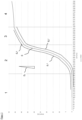
- FIG. 1 shows the diagram in which, as an example and not a limitation, the work performed during a flow hole and thread forming process (joining process) with a flow hole screw as a joining element is plotted as process variable E over time.
- the joining process is divided by vertical dividing lines into its individual process steps, which take place one after the other.
- the process step " finding" begins, which lasts for about 300 ms.
- the screw is placed on the workpiece (finding).
- the work done here (placing the screw or the joining element on the workpiece with light pressure) adds up to about 0.5 kJ.
- the " pull-through forming" process follows, in which the joining element is pressed against the workpiece at a greatly increased speed and with increased pressure. This heats up the workpiece and eventually begins to flow around the screw tip so that the screw can be pressed into the workpiece.
- This process step takes about 240 ms. You can see the clear increase in the work performed, which is about 36.5 kj for this process step alone.
- the process variable E plotted as a cumulative curve, is therefore about 37 kj at the start of the third process step.
- the joining element is screwed into the workpiece at a greatly reduced speed and a largely constant feed rate, forming a thread ( "thread forming” ) .
- the screw head After the thread has been fully formed, the screw head reaches the workpiece surface (head support) in the 4th process stage, and the penetration depth does not change significantly after that.
- the screw is tightened to the final tightening torque ("final tightening "), for which another approx. 2 kJ of work is performed within approx. 200 ms.
- final tightening In the entire joining process, a total of around 48 kJ of work was performed within approx. 900 ms, which is why the process variable E at the end of the joining process represents approximately this value.
- Figure 1 shows several comparison values E 1 *, E 2 *, E 3 *, E 4 * as examples, which can be used individually or together for comparison with the process variable E in order to evaluate the proper course of the joining process.
- the first comparison value E 1 * is designed as a curve that represents the maximum work to be done during the second process step " pull-through forming" . For each point in time within this process step, E 1 * indicates the value of the work to be done that the observed process variable E must not exceed if the "IO" criterion is still to be considered fulfilled. If the process variable E exceeds the comparison value E 1 * during the process, the control unit carrying out the comparison could abort the joining process and issue a corresponding message.
- the second comparison value E 2 * also designed as a curve, represents an energy value dependent on time (or on penetration depth), which the process variable E must not fall below in order to fulfill the criterion "IO".
- a constant gradient [kj/t] was specified, which describes the maximum permissible change in the work performed per time that is still an "IO" evaluation is permitted.
- the third comparison value E 3 * could be used to check the corresponding behavior of the process variable E. If the work performed in the process E/t increases faster than described by the gradient E 3 *, this could be used as a termination criterion (analogously, a minimum gradient could also be specified).
- the fourth comparison value E 4 * is a constant value and represents the maximum permissible work performed until the end of the pull-through forming process (and in this example lies on the curve of the first comparison value E 1 *). If it is sufficient to evaluate the second process step by looking at the total work or energy expended at the end, the fourth comparison value E 4 * can be used alone, which simplifies the overall evaluation.
- comparison values can be specified simultaneously or consecutively in order to be able to evaluate the process as "OK” or "NIO” from the comparison between E and E* in the ongoing process and/or at certain process events (e.g. completion of a process step). It is particularly preferred to use at least one comparison value for individual process steps that can only be used for this process step.
Landscapes
- Engineering & Computer Science (AREA)
- Mechanical Engineering (AREA)
- Human Computer Interaction (AREA)
- Manufacturing & Machinery (AREA)
- Physics & Mathematics (AREA)
- General Physics & Mathematics (AREA)
- Automation & Control Theory (AREA)
- Forging (AREA)
- Lining Or Joining Of Plastics Or The Like (AREA)
- Automatic Assembly (AREA)
- General Factory Administration (AREA)
Claims (9)
- Procédé pour la surveillance et/ou la régulation d'un processus de mise en forme par fluotournage et taraudage, dans lequel un élément d'assemblage, en particulier une vis pour fluotournage, présentant une section filetée est entraîné dans et à travers une pièce à une vitesse de rotation (N), avec un couple de rotation (M) et avec une force d'avance (F) en suivant un chemin (Z) (profondeur de pénétration), comprenant les étapes de procédé suivantes :a) formation d'au moins une grandeur de processus (E) à l'aide de l'énergie dépensée pour la réalisation du procédé ou d'une valeur auxiliaire qui en est dérivée ;b) comparaison de la grandeur de processus (E) ainsi recueillie avec au moins une valeur de comparaison (E*, E1*, E2*...) prédéfinie pour la réalisation du procédé ou déterminée pendant celui-ci ;c) émission d'un signal de commande et/ou d'affichage dépendant de ladite comparaison afin d'indiquer le déroulement correct ou incorrect du procédé et/ou de commander le procédé en fonction de la comparaison,
caractérisé en ced) que la grandeur de processus (E) est formée en additionnant l'énergie dépensée depuis un événement de démarrage pouvant être prédéfini jusqu'à un événement de procédé pouvant être prédéfini ou une valeur auxiliaire qui en est dérivée. - Procédé selon la revendication 1, caractérisé en ce qu'une seconde grandeur de processus est formée au moyen d'un gradient (E3) qui met en relation l'énergie actuellement dépensée ou une valeur auxiliaire qui en est dérivée avec le temps (t) ou la profondeur de pénétration (Z) ou la vitesse de rotation (N) ou la force d'avance (F).
- Procédé selon la revendication 1 ou 2, caractérisé en ce que le processus de mise en forme par fluotournage et taraudage est divisé en étapes de processus successives, dans lequel au moins une valeur de comparaison (E*, E1*, E2*...) associée à chaque étape de processus est enregistrée dans une commande pour chaque étape de processus.
- Procédé selon les revendications 2 et 3, caractérisé en ce que la grandeur de processus (E) est comparée pendant une étape de processus avec la valeur de comparaison (E*, E1*, E2*...) associée.
- Procédé selon la revendication 3, caractérisé en ce que la grandeur de processus (E) est comparée, après l'achèvement d'une ou de plusieurs étapes de processus, avec la somme des valeurs de comparaison (E*) individuelles des étapes de processus achevées jusqu'ici.
- Procédé selon l'une des revendications précédentes,
caractérisé en ce que le processus de mise en forme par fluotournage et taraudage comprend les étapes de processus suivantes :1. mise en place de l'élément d'assemblage sur la pièce (trouver) ;2. augmentation de la vitesse de rotation (N) et pressage de l'élément d'assemblage contre la pièce jusqu'à ce que la pièce commence à s'écouler, dans lequel l'élément d'assemblage est alors pressé dans la pièce jusqu'au début de la section filetée (mettre en forme par passage) ;3. vissage de l'élément d'assemblage dans la pièce avec formation simultanée d'un taraudage dans la pièce (mettre en forme par taraudage) ;4. vissage de l'élément d'assemblage dans la pièce jusqu'à ce qu'une tête de l'élément d'assemblage repose sur la pièce et serrage de l'élément d'assemblage (serrer pour finir). - Procédé selon l'une des revendications précédentes,
caractérisé en ce que les valeurs de comparaison (E*, E1*, E2*...) à utiliser pour la comparaison avec la grandeur de processus (E) sont fournies en fonction de paramètres de processus, dans lequel lesdits paramètres de processus peuvent inclure la géométrie et/ou le matériau de l'élément d'assemblage et/ou de la pièce. - Procédé selon l'une des revendications précédentes,
caractérisé en ce qu'une ou plusieurs des valeurs de comparaison (E*, E1*, E2*...) sont générées automatiquement et stockées dans une mémoire à l'aide des grandeurs de processus (E) qui ont été déterminées pour une pluralité de processus de mise en forme par fluotournage et taraudage précédemment achevés avec succès (apprendre). - Dispositif d'assemblage, conçu pour la réalisation du procédé selon l'une des revendications précédentes, comprenant une unité de commande configurée pour la comparaison entre la grandeur de processus (E), laquelle est formée en additionnant l'énergie dépensée depuis un événement de démarrage pouvant être prédéfini jusqu'à un événement de procédé pouvant être prédéfini ou une valeur auxiliaire qui en est dérivée, et une valeur de comparaison (E*, E1*, E2*...) correspondante, dans lequel l'unité de commande est en outre configurée pour interrompre le procédé et/ou émettre un message d'erreur correspondant en fonction du résultat de la comparaison, de préférence en tenant compte de tolérances pouvant être prédéfinies.
Applications Claiming Priority (1)
| Application Number | Priority Date | Filing Date | Title |
|---|---|---|---|
| DE102021115209.7A DE102021115209B4 (de) | 2021-06-11 | 2021-06-11 | Verfahren und Vorrichtung zur Überwachung und/oder Regelung eines Fließloch- und Gewindeformprozesses |
Publications (3)
| Publication Number | Publication Date |
|---|---|
| EP4101570A1 EP4101570A1 (fr) | 2022-12-14 |
| EP4101570B1 true EP4101570B1 (fr) | 2024-11-20 |
| EP4101570C0 EP4101570C0 (fr) | 2024-11-20 |
Family
ID=81940501
Family Applications (1)
| Application Number | Title | Priority Date | Filing Date |
|---|---|---|---|
| EP22177179.3A Active EP4101570B1 (fr) | 2021-06-11 | 2022-06-03 | Procédé et dispositif de surveillance et/ou de régulation d'un processus de formation de trou d'écoulement et de filetage |
Country Status (4)
| Country | Link |
|---|---|
| US (1) | US12246374B2 (fr) |
| EP (1) | EP4101570B1 (fr) |
| CN (1) | CN114850853B (fr) |
| DE (1) | DE102021115209B4 (fr) |
Families Citing this family (2)
| Publication number | Priority date | Publication date | Assignee | Title |
|---|---|---|---|---|
| CN117754061B (zh) * | 2023-12-19 | 2025-04-18 | 湖南大学苏州研究院 | 基于人工神经网络的热熔自攻丝连接优化方法和优化系统 |
| DE102024110303A1 (de) * | 2024-04-12 | 2025-10-16 | Atlas Copco Ias Gmbh | Verfahren und Verbindungsvorrichtung zum Verbinden von zumindest zwei Elementen durch ein Verbindungselement |
Family Cites Families (30)
| Publication number | Priority date | Publication date | Assignee | Title |
|---|---|---|---|---|
| DE3511400A1 (de) * | 1985-03-29 | 1986-10-02 | Dr. Staiger, Mohilo + Co GmbH, 7060 Schorndorf | Verfahren zum ueberwachen des eindrehvorgangs einer schraube |
| DE10255177A1 (de) * | 2002-11-27 | 2004-06-09 | Bayerische Motoren Werke Ag | Verfahren zum Verschrauben von Gewindeelementen mit inhomogenen Bauteilen |
| JP2006015438A (ja) * | 2004-06-30 | 2006-01-19 | Matsushita Electric Works Ltd | インパクト締め付け工具 |
| JP4600977B2 (ja) * | 2004-10-29 | 2010-12-22 | 日東精工株式会社 | 自動ねじ締め機 |
| JP4813087B2 (ja) * | 2005-05-10 | 2011-11-09 | 富士重工業株式会社 | タッピング加工装置 |
| ITPN20050071A1 (it) * | 2005-10-12 | 2007-04-13 | Bordignon Alberto | Apparecchio maschiatore automatico perfezionato |
| JP3117939U (ja) * | 2005-10-25 | 2006-01-19 | 株式会社湖東製作所 | タッピング装置 |
| DE102007024627B3 (de) | 2007-05-24 | 2009-01-02 | Weber Schraubautomaten Gmbh | Verfahren zur Detektion und Kontrolle des Fugens oder Lösens eines Befestigungsmittels, sowie Vorrichtung zur Durchführung des Verfahrens |
| US8413307B2 (en) * | 2009-07-06 | 2013-04-09 | The Boeing Company | Guide assembly and method |
| JP5836099B2 (ja) * | 2011-12-12 | 2015-12-24 | 株式会社アマダホールディングス | タップ加工装置及び加工異常判定方法 |
| DE102012215908A1 (de) * | 2012-09-07 | 2014-05-28 | Bayerische Motoren Werke Aktiengesellschaft | Verfahren und Vorrichtung zum vorlochfreien Direktverschrauben von wenigstens zwei Bauteilen unter Einsatz eines Niederhalters |
| ES3041736T3 (en) * | 2014-02-03 | 2025-11-14 | Howmet Aerospace Inc | Resistance welding fastener, apparatus and methods |
| DE102014203274A1 (de) * | 2014-02-24 | 2015-08-27 | Bayerische Motoren Werke Aktiengesellschaft | Verfahren zum Herstellen einer Schraub-Klebverbindung unter Verwendung einer fließlochformenden Schraube, sowie hierfür verwendbare fließlochformende Schraube |
| DE102014204292A1 (de) * | 2014-03-10 | 2015-09-10 | Bayerische Motoren Werke Aktiengesellschaft | Verfahren zum Herstellen einer Schraub-Klebverbindung unter Verwendung einer fließlochformenden Schraube, sowie hiernach hergestellter Bauteilverbund |
| PL2944418T3 (pl) * | 2014-05-13 | 2019-09-30 | Deprag Schulz Gmbh U. Co. | Urządzenie do łączenia elementów, zwłaszcza za pomocą bezpośredniego skręcania, szczególnie skręcania tłoczonego lub za pomocą zgrzewania tarciowego oraz sposób łączenia elementów, zwłaszcza za pomocą skręcania bezpośredniego lub też zgrzewania tarciowego |
| DE102014208989A1 (de) * | 2014-05-13 | 2015-11-19 | Deprag Schulz Gmbh U. Co | Verfahren zum Direktverschrauben von Bauteilen, insbesondere zum Fließlochschrauben sowie Vorrichtung zum Direktverschrauben von Bauteilen |
| EP3233360B1 (fr) * | 2014-12-15 | 2022-09-28 | Howmet Aerospace Inc. | Élément de fixation à soudage par résistance, appareil et procédés destinés à joindre des matériaux similaires et non similaires |
| DE102015005759A1 (de) * | 2015-05-05 | 2015-12-03 | Daimler Ag | Verfahren und Vorrichtung zum Fügen von wenigstens zwei Bauteilen |
| US9695853B2 (en) * | 2015-11-11 | 2017-07-04 | Ford Global Technologies, Llc | High energy absorption joint |
| US10593034B2 (en) * | 2016-03-25 | 2020-03-17 | Arconic Inc. | Resistance welding fasteners, apparatus and methods for joining dissimilar materials and assessing joints made thereby |
| DE102016007332A1 (de) * | 2016-06-16 | 2017-12-21 | Daimler Ag | Verfahren und Setzgerät zum Eintreiben eines Fügeelements in wenigstens ein Bauteil |
| US10731684B2 (en) * | 2017-02-17 | 2020-08-04 | Clemson University Research Foundation | Electrically assisted flow drill screwdriving and fixture therefore |
| DE102017220431A1 (de) * | 2017-11-16 | 2019-05-16 | Bayerische Motoren Werke Aktiengesellschaft | Verfahren zur Herstellung eines Verbundbauteils |
| DE102018103205A1 (de) * | 2018-02-13 | 2019-08-14 | Ejot Gmbh & Co. Kg | Fügeelement |
| DE102018104835A1 (de) * | 2018-03-02 | 2019-09-05 | Atlas Copco Ias Gmbh | Vorrichtung zum Auftragen eines viskosen Materials auf Werkstücke |
| JP7207983B2 (ja) * | 2018-12-10 | 2023-01-18 | 株式会社Subaru | ドリル、穿孔ユニット及び被穿孔品を製作する方法 |
| DE102019207885B3 (de) * | 2019-05-29 | 2020-08-13 | Audi Ag | Verfahren zur Prozessüberwachung, Computerprogramm, Vorrichtung zur Datenverarbeitung, computerlesbares Medium und Vorrichtung zur Prozessüberwachung |
| DE102019120863A1 (de) * | 2019-08-01 | 2021-02-04 | Atlas Copco Ias Gmbh | Verfahren zur Steuerung eines mechanischen Füge- oder Umformprozesses |
| DE102019135273B4 (de) * | 2019-12-19 | 2022-08-04 | Atlas Copco Ias Gmbh | Verfahren zum Detektieren von Verbindungselementen, insbesondere Fließlochschrauben, bei mechanischen Füge- und Umformprozessen in welchem ein Fehlerfall des Prozesses erkannt wurde |
| US20230129583A1 (en) * | 2021-10-27 | 2023-04-27 | Semblex Corporation | Torque reducing flow drilling fastener for thick materials and method of using such fastener |
-
2021
- 2021-06-11 DE DE102021115209.7A patent/DE102021115209B4/de active Active
-
2022
- 2022-06-03 EP EP22177179.3A patent/EP4101570B1/fr active Active
- 2022-06-09 US US17/836,806 patent/US12246374B2/en active Active
- 2022-06-09 CN CN202210658983.2A patent/CN114850853B/zh active Active
Also Published As
| Publication number | Publication date |
|---|---|
| EP4101570A1 (fr) | 2022-12-14 |
| CN114850853A (zh) | 2022-08-05 |
| CN114850853B (zh) | 2024-09-24 |
| US12246374B2 (en) | 2025-03-11 |
| DE102021115209A1 (de) | 2022-12-15 |
| EP4101570C0 (fr) | 2024-11-20 |
| DE102021115209B4 (de) | 2024-08-01 |
| US20220395892A1 (en) | 2022-12-15 |
Similar Documents
| Publication | Publication Date | Title |
|---|---|---|
| DE60020313T2 (de) | Fehlererkennungsvorrichtung für ein Werkzeug und numerische Steuerungseinrichtung, welche mit einer solchen ausgestattet ist | |
| EP2954973B1 (fr) | Procédé de vissage direct de composants, en particulier fluo-perçage et dispositif de vissage direct de composants | |
| EP0642890B1 (fr) | Procédé pour établir un raccord, notamment un raccord à vis | |
| EP4101570B1 (fr) | Procédé et dispositif de surveillance et/ou de régulation d'un processus de formation de trou d'écoulement et de filetage | |
| EP3348347B1 (fr) | Procédé et dispositif destiné à enfoncer une vis | |
| DE112006003147T5 (de) | Fehlerüberwachungsverfahren für eine Arbeitsmaschine | |
| DE10241742B4 (de) | Fertigungsanlage zum Herstellen von Produkten | |
| EP4102316B1 (fr) | Procédé et dispositif de surveillance et/ou de régulation d'un processus de formation de fluo-perçage et de filetage | |
| DE3843450C2 (fr) | ||
| EP0264034A2 (fr) | Méthode et dispositif pour le serrage d'un assemblage par boulons | |
| WO2001098011A1 (fr) | Procede de production d'un ecrou, taraud permettant la mise en oeuvre de ce procede et ecrou ainsi obtenu | |
| WO2018153938A1 (fr) | Procédé de fonctionnement d'une installation de traitement de pièces, et installation de traitement de pièces | |
| DE102020203598A1 (de) | Steuersystem für eine industriemaschine | |
| EP3680050A2 (fr) | Procédé de vérification d'une pince à souder permettant le soudage par résistance de pièces à usiner | |
| DE69833420T2 (de) | Steuerung für industrielle Maschine | |
| DE3741973C2 (fr) | ||
| EP3760360B1 (fr) | Commande de soudage pour un outil de soudage et procédé permettant d'éviter des vibrations de force d'un outil de soudage | |
| EP4063057A1 (fr) | Procédé de soudage par résistance de pièces | |
| EP3103579B1 (fr) | Fraise de rodage comprenant un moteur electrique | |
| DE10259887A1 (de) | Verfahren zur Bearbeitung eines Werkstücks mit einer geregelten Werkzeugmaschine | |
| CH694288A5 (de) | Funkenerosionsmaschine. | |
| EP4108427B1 (fr) | Procédé de commande d'un processus de traitement | |
| EP3808491B1 (fr) | Procédé de soudage par résistance des pièces | |
| DE29813363U1 (de) | Frässystem | |
| WO2026046984A1 (fr) | Procédé de détection de l'usure d'un outil |
Legal Events
| Date | Code | Title | Description |
|---|---|---|---|
| PUAI | Public reference made under article 153(3) epc to a published international application that has entered the european phase |
Free format text: ORIGINAL CODE: 0009012 |
|
| STAA | Information on the status of an ep patent application or granted ep patent |
Free format text: STATUS: THE APPLICATION HAS BEEN PUBLISHED |
|
| AK | Designated contracting states |
Kind code of ref document: A1 Designated state(s): AL AT BE BG CH CY CZ DE DK EE ES FI FR GB GR HR HU IE IS IT LI LT LU LV MC MK MT NL NO PL PT RO RS SE SI SK SM TR |
|
| STAA | Information on the status of an ep patent application or granted ep patent |
Free format text: STATUS: REQUEST FOR EXAMINATION WAS MADE |
|
| 17P | Request for examination filed |
Effective date: 20230313 |
|
| RBV | Designated contracting states (corrected) |
Designated state(s): AL AT BE BG CH CY CZ DE DK EE ES FI FR GB GR HR HU IE IS IT LI LT LU LV MC MK MT NL NO PL PT RO RS SE SI SK SM TR |
|
| STAA | Information on the status of an ep patent application or granted ep patent |
Free format text: STATUS: EXAMINATION IS IN PROGRESS |
|
| 17Q | First examination report despatched |
Effective date: 20230913 |
|
| GRAP | Despatch of communication of intention to grant a patent |
Free format text: ORIGINAL CODE: EPIDOSNIGR1 |
|
| STAA | Information on the status of an ep patent application or granted ep patent |
Free format text: STATUS: GRANT OF PATENT IS INTENDED |
|
| INTG | Intention to grant announced |
Effective date: 20240422 |
|
| GRAS | Grant fee paid |
Free format text: ORIGINAL CODE: EPIDOSNIGR3 |
|
| GRAJ | Information related to disapproval of communication of intention to grant by the applicant or resumption of examination proceedings by the epo deleted |
Free format text: ORIGINAL CODE: EPIDOSDIGR1 |
|
| GRAL | Information related to payment of fee for publishing/printing deleted |
Free format text: ORIGINAL CODE: EPIDOSDIGR3 |
|
| STAA | Information on the status of an ep patent application or granted ep patent |
Free format text: STATUS: EXAMINATION IS IN PROGRESS |
|
| GRAP | Despatch of communication of intention to grant a patent |
Free format text: ORIGINAL CODE: EPIDOSNIGR1 |
|
| STAA | Information on the status of an ep patent application or granted ep patent |
Free format text: STATUS: GRANT OF PATENT IS INTENDED |
|
| INTC | Intention to grant announced (deleted) | ||
| GRAA | (expected) grant |
Free format text: ORIGINAL CODE: 0009210 |
|
| STAA | Information on the status of an ep patent application or granted ep patent |
Free format text: STATUS: THE PATENT HAS BEEN GRANTED |
|
| INTG | Intention to grant announced |
Effective date: 20240927 |
|
| AK | Designated contracting states |
Kind code of ref document: B1 Designated state(s): AL AT BE BG CH CY CZ DE DK EE ES FI FR GB GR HR HU IE IS IT LI LT LU LV MC MK MT NL NO PL PT RO RS SE SI SK SM TR |
|
| REG | Reference to a national code |
Ref country code: GB Ref legal event code: FG4D Free format text: NOT ENGLISH |
|
| REG | Reference to a national code |
Ref country code: CH Ref legal event code: EP |
|
| REG | Reference to a national code |
Ref country code: DE Ref legal event code: R096 Ref document number: 502022002156 Country of ref document: DE |
|
| REG | Reference to a national code |
Ref country code: IE Ref legal event code: FG4D Free format text: LANGUAGE OF EP DOCUMENT: GERMAN |
|
| U01 | Request for unitary effect filed |
Effective date: 20241218 |
|
| U07 | Unitary effect registered |
Designated state(s): AT BE BG DE DK EE FI FR IT LT LU LV MT NL PT RO SE SI Effective date: 20250103 |
|
| PG25 | Lapsed in a contracting state [announced via postgrant information from national office to epo] |
Ref country code: HR Free format text: LAPSE BECAUSE OF FAILURE TO SUBMIT A TRANSLATION OF THE DESCRIPTION OR TO PAY THE FEE WITHIN THE PRESCRIBED TIME-LIMIT Effective date: 20241120 Ref country code: IS Free format text: LAPSE BECAUSE OF FAILURE TO SUBMIT A TRANSLATION OF THE DESCRIPTION OR TO PAY THE FEE WITHIN THE PRESCRIBED TIME-LIMIT Effective date: 20250320 |
|
| PG25 | Lapsed in a contracting state [announced via postgrant information from national office to epo] |
Ref country code: ES Free format text: LAPSE BECAUSE OF FAILURE TO SUBMIT A TRANSLATION OF THE DESCRIPTION OR TO PAY THE FEE WITHIN THE PRESCRIBED TIME-LIMIT Effective date: 20241120 |
|
| PG25 | Lapsed in a contracting state [announced via postgrant information from national office to epo] |
Ref country code: NO Free format text: LAPSE BECAUSE OF FAILURE TO SUBMIT A TRANSLATION OF THE DESCRIPTION OR TO PAY THE FEE WITHIN THE PRESCRIBED TIME-LIMIT Effective date: 20250220 |
|
| PG25 | Lapsed in a contracting state [announced via postgrant information from national office to epo] |
Ref country code: GR Free format text: LAPSE BECAUSE OF FAILURE TO SUBMIT A TRANSLATION OF THE DESCRIPTION OR TO PAY THE FEE WITHIN THE PRESCRIBED TIME-LIMIT Effective date: 20250221 |
|
| PG25 | Lapsed in a contracting state [announced via postgrant information from national office to epo] |
Ref country code: PL Free format text: LAPSE BECAUSE OF FAILURE TO SUBMIT A TRANSLATION OF THE DESCRIPTION OR TO PAY THE FEE WITHIN THE PRESCRIBED TIME-LIMIT Effective date: 20241120 |
|
| PG25 | Lapsed in a contracting state [announced via postgrant information from national office to epo] |
Ref country code: RS Free format text: LAPSE BECAUSE OF FAILURE TO SUBMIT A TRANSLATION OF THE DESCRIPTION OR TO PAY THE FEE WITHIN THE PRESCRIBED TIME-LIMIT Effective date: 20250220 |
|
| U20 | Renewal fee for the european patent with unitary effect paid |
Year of fee payment: 4 Effective date: 20250518 |
|
| PG25 | Lapsed in a contracting state [announced via postgrant information from national office to epo] |
Ref country code: SM Free format text: LAPSE BECAUSE OF FAILURE TO SUBMIT A TRANSLATION OF THE DESCRIPTION OR TO PAY THE FEE WITHIN THE PRESCRIBED TIME-LIMIT Effective date: 20241120 |
|
| PG25 | Lapsed in a contracting state [announced via postgrant information from national office to epo] |
Ref country code: SK Free format text: LAPSE BECAUSE OF FAILURE TO SUBMIT A TRANSLATION OF THE DESCRIPTION OR TO PAY THE FEE WITHIN THE PRESCRIBED TIME-LIMIT Effective date: 20241120 |
|
| PG25 | Lapsed in a contracting state [announced via postgrant information from national office to epo] |
Ref country code: CZ Free format text: LAPSE BECAUSE OF FAILURE TO SUBMIT A TRANSLATION OF THE DESCRIPTION OR TO PAY THE FEE WITHIN THE PRESCRIBED TIME-LIMIT Effective date: 20241120 |
|
| PLBE | No opposition filed within time limit |
Free format text: ORIGINAL CODE: 0009261 |
|
| STAA | Information on the status of an ep patent application or granted ep patent |
Free format text: STATUS: NO OPPOSITION FILED WITHIN TIME LIMIT |
|
| 26N | No opposition filed |
Effective date: 20250821 |
|
| REG | Reference to a national code |
Ref country code: CH Ref legal event code: H13 Free format text: ST27 STATUS EVENT CODE: U-0-0-H10-H13 (AS PROVIDED BY THE NATIONAL OFFICE) Effective date: 20260127 |
|
| PG25 | Lapsed in a contracting state [announced via postgrant information from national office to epo] |
Ref country code: MC Free format text: LAPSE BECAUSE OF FAILURE TO SUBMIT A TRANSLATION OF THE DESCRIPTION OR TO PAY THE FEE WITHIN THE PRESCRIBED TIME-LIMIT Effective date: 20241120 |