EP4101547A1 - Electrode coating device and electrode coating method - Google Patents
Electrode coating device and electrode coating method Download PDFInfo
- Publication number
- EP4101547A1 EP4101547A1 EP21892240.9A EP21892240A EP4101547A1 EP 4101547 A1 EP4101547 A1 EP 4101547A1 EP 21892240 A EP21892240 A EP 21892240A EP 4101547 A1 EP4101547 A1 EP 4101547A1
- Authority
- EP
- European Patent Office
- Prior art keywords
- thickness
- electrode
- coated
- electrode slurry
- coating
- Prior art date
- Legal status (The legal status is an assumption and is not a legal conclusion. Google has not performed a legal analysis and makes no representation as to the accuracy of the status listed.)
- Pending
Links
- 238000000576 coating method Methods 0.000 title claims abstract description 154
- 239000011248 coating agent Substances 0.000 title claims abstract description 135
- 239000011267 electrode slurry Substances 0.000 claims abstract description 176
- 238000001035 drying Methods 0.000 claims description 32
- 238000000034 method Methods 0.000 claims description 11
- OKTJSMMVPCPJKN-UHFFFAOYSA-N Carbon Chemical compound [C] OKTJSMMVPCPJKN-UHFFFAOYSA-N 0.000 description 15
- 238000005259 measurement Methods 0.000 description 13
- 239000002002 slurry Substances 0.000 description 12
- PXHVJJICTQNCMI-UHFFFAOYSA-N Nickel Chemical compound [Ni] PXHVJJICTQNCMI-UHFFFAOYSA-N 0.000 description 10
- 238000010586 diagram Methods 0.000 description 10
- 229910052782 aluminium Inorganic materials 0.000 description 9
- 239000004020 conductor Substances 0.000 description 8
- 229910052799 carbon Inorganic materials 0.000 description 7
- 238000002347 injection Methods 0.000 description 7
- 239000007924 injection Substances 0.000 description 7
- 239000011230 binding agent Substances 0.000 description 6
- 239000007772 electrode material Substances 0.000 description 6
- 239000007773 negative electrode material Substances 0.000 description 6
- 239000007774 positive electrode material Substances 0.000 description 6
- 229910052802 copper Inorganic materials 0.000 description 5
- 239000010949 copper Substances 0.000 description 5
- 229910052759 nickel Inorganic materials 0.000 description 5
- 230000008569 process Effects 0.000 description 5
- 239000002904 solvent Substances 0.000 description 5
- 239000010936 titanium Substances 0.000 description 5
- 229910052719 titanium Inorganic materials 0.000 description 5
- RYGMFSIKBFXOCR-UHFFFAOYSA-N Copper Chemical compound [Cu] RYGMFSIKBFXOCR-UHFFFAOYSA-N 0.000 description 4
- IAZDPXIOMUYVGZ-UHFFFAOYSA-N Dimethylsulphoxide Chemical compound CS(C)=O IAZDPXIOMUYVGZ-UHFFFAOYSA-N 0.000 description 4
- RTAQQCXQSZGOHL-UHFFFAOYSA-N Titanium Chemical compound [Ti] RTAQQCXQSZGOHL-UHFFFAOYSA-N 0.000 description 4
- XAGFODPZIPBFFR-UHFFFAOYSA-N aluminium Chemical compound [Al] XAGFODPZIPBFFR-UHFFFAOYSA-N 0.000 description 4
- -1 aluminum-cadmium Chemical compound 0.000 description 4
- 238000009826 distribution Methods 0.000 description 4
- 229910002804 graphite Inorganic materials 0.000 description 4
- 239000010439 graphite Substances 0.000 description 4
- 239000000203 mixture Substances 0.000 description 4
- 229910001220 stainless steel Inorganic materials 0.000 description 4
- 239000010935 stainless steel Substances 0.000 description 4
- 229910052723 transition metal Inorganic materials 0.000 description 4
- 150000003624 transition metals Chemical class 0.000 description 4
- 229920002134 Carboxymethyl cellulose Polymers 0.000 description 3
- KFZMGEQAYNKOFK-UHFFFAOYSA-N Isopropanol Chemical compound CC(C)O KFZMGEQAYNKOFK-UHFFFAOYSA-N 0.000 description 3
- HBBGRARXTFLTSG-UHFFFAOYSA-N Lithium ion Chemical compound [Li+] HBBGRARXTFLTSG-UHFFFAOYSA-N 0.000 description 3
- 239000011149 active material Substances 0.000 description 3
- 229910052796 boron Inorganic materials 0.000 description 3
- 230000008859 change Effects 0.000 description 3
- 229910052731 fluorine Inorganic materials 0.000 description 3
- 229910052742 iron Inorganic materials 0.000 description 3
- 229910052744 lithium Inorganic materials 0.000 description 3
- 229910001416 lithium ion Inorganic materials 0.000 description 3
- 229910052749 magnesium Inorganic materials 0.000 description 3
- 229910052748 manganese Inorganic materials 0.000 description 3
- 239000011572 manganese Substances 0.000 description 3
- 238000004519 manufacturing process Methods 0.000 description 3
- 229910052751 metal Inorganic materials 0.000 description 3
- 239000002184 metal Substances 0.000 description 3
- 229920000642 polymer Polymers 0.000 description 3
- 239000000126 substance Substances 0.000 description 3
- XLYOFNOQVPJJNP-UHFFFAOYSA-N water Substances O XLYOFNOQVPJJNP-UHFFFAOYSA-N 0.000 description 3
- CSCPPACGZOOCGX-UHFFFAOYSA-N Acetone Chemical compound CC(C)=O CSCPPACGZOOCGX-UHFFFAOYSA-N 0.000 description 2
- SECXISVLQFMRJM-UHFFFAOYSA-N N-Methylpyrrolidone Chemical compound CN1CCCC1=O SECXISVLQFMRJM-UHFFFAOYSA-N 0.000 description 2
- BQCADISMDOOEFD-UHFFFAOYSA-N Silver Chemical compound [Ag] BQCADISMDOOEFD-UHFFFAOYSA-N 0.000 description 2
- XLOMVQKBTHCTTD-UHFFFAOYSA-N Zinc monoxide Chemical compound [Zn]=O XLOMVQKBTHCTTD-UHFFFAOYSA-N 0.000 description 2
- 239000003125 aqueous solvent Substances 0.000 description 2
- 230000008901 benefit Effects 0.000 description 2
- WMWLMWRWZQELOS-UHFFFAOYSA-N bismuth(iii) oxide Chemical compound O=[Bi]O[Bi]=O WMWLMWRWZQELOS-UHFFFAOYSA-N 0.000 description 2
- 239000001768 carboxy methyl cellulose Substances 0.000 description 2
- 235000010948 carboxy methyl cellulose Nutrition 0.000 description 2
- 239000008112 carboxymethyl-cellulose Substances 0.000 description 2
- 229910052804 chromium Inorganic materials 0.000 description 2
- 230000007547 defect Effects 0.000 description 2
- 238000007599 discharging Methods 0.000 description 2
- 229920001971 elastomer Polymers 0.000 description 2
- 239000003792 electrolyte Substances 0.000 description 2
- 239000000835 fiber Substances 0.000 description 2
- 239000006260 foam Substances 0.000 description 2
- 239000011888 foil Substances 0.000 description 2
- YBMRDBCBODYGJE-UHFFFAOYSA-N germanium dioxide Chemical compound O=[Ge]=O YBMRDBCBODYGJE-UHFFFAOYSA-N 0.000 description 2
- 229910000625 lithium cobalt oxide Inorganic materials 0.000 description 2
- BFZPBUKRYWOWDV-UHFFFAOYSA-N lithium;oxido(oxo)cobalt Chemical compound [Li+].[O-][Co]=O BFZPBUKRYWOWDV-UHFFFAOYSA-N 0.000 description 2
- 239000000463 material Substances 0.000 description 2
- 229910044991 metal oxide Inorganic materials 0.000 description 2
- 150000004706 metal oxides Chemical class 0.000 description 2
- 239000004745 nonwoven fabric Substances 0.000 description 2
- 229910052698 phosphorus Inorganic materials 0.000 description 2
- 239000000523 sample Substances 0.000 description 2
- 229910052710 silicon Inorganic materials 0.000 description 2
- 229910052709 silver Inorganic materials 0.000 description 2
- 239000004332 silver Substances 0.000 description 2
- 239000000243 solution Substances 0.000 description 2
- 239000002562 thickening agent Substances 0.000 description 2
- XOLBLPGZBRYERU-UHFFFAOYSA-N tin dioxide Chemical compound O=[Sn]=O XOLBLPGZBRYERU-UHFFFAOYSA-N 0.000 description 2
- 229920000049 Carbon (fiber) Polymers 0.000 description 1
- 229910000925 Cd alloy Inorganic materials 0.000 description 1
- 229920002943 EPDM rubber Polymers 0.000 description 1
- YCKRFDGAMUMZLT-UHFFFAOYSA-N Fluorine atom Chemical compound [F] YCKRFDGAMUMZLT-UHFFFAOYSA-N 0.000 description 1
- 229920002153 Hydroxypropyl cellulose Polymers 0.000 description 1
- 229910000733 Li alloy Inorganic materials 0.000 description 1
- 229910007969 Li-Co-Ni Inorganic materials 0.000 description 1
- 229910007177 Li1+zNi0.4Mn0.4Co0.2O2 Inorganic materials 0.000 description 1
- 229910007180 Li1+zNi1/3Co1/3Mn1/3O2 Inorganic materials 0.000 description 1
- 229910014383 LiNi1-yMyO2 Inorganic materials 0.000 description 1
- 229910014952 LiNi1−yMyO2 Inorganic materials 0.000 description 1
- WHXSMMKQMYFTQS-UHFFFAOYSA-N Lithium Chemical compound [Li] WHXSMMKQMYFTQS-UHFFFAOYSA-N 0.000 description 1
- 229910016622 LixFe2O3 Inorganic materials 0.000 description 1
- 229910015103 LixWO2 Inorganic materials 0.000 description 1
- 229910006555 Li—Co—Ni Inorganic materials 0.000 description 1
- 229910019142 PO4 Inorganic materials 0.000 description 1
- 239000002033 PVDF binder Substances 0.000 description 1
- 239000004698 Polyethylene Substances 0.000 description 1
- 229920000265 Polyparaphenylene Polymers 0.000 description 1
- 239000004743 Polypropylene Substances 0.000 description 1
- 239000004372 Polyvinyl alcohol Substances 0.000 description 1
- 229910000676 Si alloy Inorganic materials 0.000 description 1
- 229910001128 Sn alloy Inorganic materials 0.000 description 1
- 229920002472 Starch Polymers 0.000 description 1
- PPBRXRYQALVLMV-UHFFFAOYSA-N Styrene Natural products C=CC1=CC=CC=C1 PPBRXRYQALVLMV-UHFFFAOYSA-N 0.000 description 1
- GWEVSGVZZGPLCZ-UHFFFAOYSA-N Titan oxide Chemical compound O=[Ti]=O GWEVSGVZZGPLCZ-UHFFFAOYSA-N 0.000 description 1
- SOXUFMZTHZXOGC-UHFFFAOYSA-N [Li].[Mn].[Co].[Ni] Chemical compound [Li].[Mn].[Co].[Ni] SOXUFMZTHZXOGC-UHFFFAOYSA-N 0.000 description 1
- 239000006230 acetylene black Substances 0.000 description 1
- 238000003915 air pollution Methods 0.000 description 1
- HSFWRNGVRCDJHI-UHFFFAOYSA-N alpha-acetylene Natural products C#C HSFWRNGVRCDJHI-UHFFFAOYSA-N 0.000 description 1
- AZDRQVAHHNSJOQ-UHFFFAOYSA-N alumane Chemical compound [AlH3] AZDRQVAHHNSJOQ-UHFFFAOYSA-N 0.000 description 1
- LJCFOYOSGPHIOO-UHFFFAOYSA-N antimony pentoxide Inorganic materials O=[Sb](=O)O[Sb](=O)=O LJCFOYOSGPHIOO-UHFFFAOYSA-N 0.000 description 1
- 229910000411 antimony tetroxide Inorganic materials 0.000 description 1
- GHPGOEFPKIHBNM-UHFFFAOYSA-N antimony(3+);oxygen(2-) Chemical compound [O-2].[O-2].[O-2].[Sb+3].[Sb+3] GHPGOEFPKIHBNM-UHFFFAOYSA-N 0.000 description 1
- 229910021383 artificial graphite Inorganic materials 0.000 description 1
- 230000015572 biosynthetic process Effects 0.000 description 1
- 229910000417 bismuth pentoxide Inorganic materials 0.000 description 1
- 239000006229 carbon black Substances 0.000 description 1
- 239000004917 carbon fiber Substances 0.000 description 1
- 239000006231 channel black Substances 0.000 description 1
- 229910052801 chlorine Inorganic materials 0.000 description 1
- 239000002131 composite material Substances 0.000 description 1
- 150000001875 compounds Chemical class 0.000 description 1
- 229920001940 conductive polymer Polymers 0.000 description 1
- 150000004696 coordination complex Chemical class 0.000 description 1
- 229920001577 copolymer Polymers 0.000 description 1
- 230000002542 deteriorative effect Effects 0.000 description 1
- 238000007607 die coating method Methods 0.000 description 1
- NJLLQSBAHIKGKF-UHFFFAOYSA-N dipotassium dioxido(oxo)titanium Chemical compound [K+].[K+].[O-][Ti]([O-])=O NJLLQSBAHIKGKF-UHFFFAOYSA-N 0.000 description 1
- 230000000694 effects Effects 0.000 description 1
- 238000003487 electrochemical reaction Methods 0.000 description 1
- 238000005516 engineering process Methods 0.000 description 1
- 239000011737 fluorine Substances 0.000 description 1
- 239000002803 fossil fuel Substances 0.000 description 1
- 239000006232 furnace black Substances 0.000 description 1
- 229910052733 gallium Inorganic materials 0.000 description 1
- 229910052732 germanium Inorganic materials 0.000 description 1
- PVADDRMAFCOOPC-UHFFFAOYSA-N germanium monoxide Inorganic materials [Ge]=O PVADDRMAFCOOPC-UHFFFAOYSA-N 0.000 description 1
- 230000005484 gravity Effects 0.000 description 1
- 229910052736 halogen Inorganic materials 0.000 description 1
- 150000002367 halogens Chemical class 0.000 description 1
- 239000001863 hydroxypropyl cellulose Substances 0.000 description 1
- 235000010977 hydroxypropyl cellulose Nutrition 0.000 description 1
- 239000003273 ketjen black Substances 0.000 description 1
- 239000006233 lamp black Substances 0.000 description 1
- 229910052745 lead Inorganic materials 0.000 description 1
- YADSGOSSYOOKMP-UHFFFAOYSA-N lead dioxide Inorganic materials O=[Pb]=O YADSGOSSYOOKMP-UHFFFAOYSA-N 0.000 description 1
- YEXPOXQUZXUXJW-UHFFFAOYSA-N lead(II) oxide Inorganic materials [Pb]=O YEXPOXQUZXUXJW-UHFFFAOYSA-N 0.000 description 1
- XMFOQHDPRMAJNU-UHFFFAOYSA-N lead(II,IV) oxide Inorganic materials O1[Pb]O[Pb]11O[Pb]O1 XMFOQHDPRMAJNU-UHFFFAOYSA-N 0.000 description 1
- 239000007788 liquid Substances 0.000 description 1
- 239000001989 lithium alloy Substances 0.000 description 1
- 229910002102 lithium manganese oxide Inorganic materials 0.000 description 1
- 229910021437 lithium-transition metal oxide Inorganic materials 0.000 description 1
- VROAXDSNYPAOBJ-UHFFFAOYSA-N lithium;oxido(oxo)nickel Chemical group [Li+].[O-][Ni]=O VROAXDSNYPAOBJ-UHFFFAOYSA-N 0.000 description 1
- VLXXBCXTUVRROQ-UHFFFAOYSA-N lithium;oxido-oxo-(oxomanganiooxy)manganese Chemical group [Li+].[O-][Mn](=O)O[Mn]=O VLXXBCXTUVRROQ-UHFFFAOYSA-N 0.000 description 1
- URIIGZKXFBNRAU-UHFFFAOYSA-N lithium;oxonickel Chemical group [Li].[Ni]=O URIIGZKXFBNRAU-UHFFFAOYSA-N 0.000 description 1
- 238000000691 measurement method Methods 0.000 description 1
- VNWKTOKETHGBQD-UHFFFAOYSA-N methane Chemical compound C VNWKTOKETHGBQD-UHFFFAOYSA-N 0.000 description 1
- 238000012986 modification Methods 0.000 description 1
- 230000004048 modification Effects 0.000 description 1
- 229910021382 natural graphite Inorganic materials 0.000 description 1
- 229910052757 nitrogen Inorganic materials 0.000 description 1
- 239000010450 olivine Substances 0.000 description 1
- 229910052609 olivine Inorganic materials 0.000 description 1
- 230000003287 optical effect Effects 0.000 description 1
- 230000000737 periodic effect Effects 0.000 description 1
- NBIIXXVUZAFLBC-UHFFFAOYSA-K phosphate Chemical compound [O-]P([O-])([O-])=O NBIIXXVUZAFLBC-UHFFFAOYSA-K 0.000 description 1
- 239000010452 phosphate Substances 0.000 description 1
- 229920001197 polyacetylene Polymers 0.000 description 1
- 229920000573 polyethylene Polymers 0.000 description 1
- 229920001155 polypropylene Polymers 0.000 description 1
- 229920002451 polyvinyl alcohol Polymers 0.000 description 1
- 229920002981 polyvinylidene fluoride Polymers 0.000 description 1
- 229920000036 polyvinylpyrrolidone Polymers 0.000 description 1
- 239000001267 polyvinylpyrrolidone Substances 0.000 description 1
- 235000013855 polyvinylpyrrolidone Nutrition 0.000 description 1
- 239000011148 porous material Substances 0.000 description 1
- 239000000843 powder Substances 0.000 description 1
- 239000004627 regenerated cellulose Substances 0.000 description 1
- 238000005096 rolling process Methods 0.000 description 1
- 238000001228 spectrum Methods 0.000 description 1
- 239000008107 starch Substances 0.000 description 1
- 235000019698 starch Nutrition 0.000 description 1
- 229920005608 sulfonated EPDM Polymers 0.000 description 1
- 229910052717 sulfur Inorganic materials 0.000 description 1
- BFKJFAAPBSQJPD-UHFFFAOYSA-N tetrafluoroethene Chemical group FC(F)=C(F)F BFKJFAAPBSQJPD-UHFFFAOYSA-N 0.000 description 1
- TXEYQDLBPFQVAA-UHFFFAOYSA-N tetrafluoromethane Chemical compound FC(F)(F)F TXEYQDLBPFQVAA-UHFFFAOYSA-N 0.000 description 1
- QHGNHLZPVBIIPX-UHFFFAOYSA-N tin(II) oxide Inorganic materials [Sn]=O QHGNHLZPVBIIPX-UHFFFAOYSA-N 0.000 description 1
- OGIDPMRJRNCKJF-UHFFFAOYSA-N titanium oxide Inorganic materials [Ti]=O OGIDPMRJRNCKJF-UHFFFAOYSA-N 0.000 description 1
- 235000015041 whisky Nutrition 0.000 description 1
- 229910052727 yttrium Inorganic materials 0.000 description 1
- 229910052725 zinc Inorganic materials 0.000 description 1
- 239000011701 zinc Substances 0.000 description 1
- 239000011787 zinc oxide Substances 0.000 description 1
Images


Classifications
-
- B—PERFORMING OPERATIONS; TRANSPORTING
- B05—SPRAYING OR ATOMISING IN GENERAL; APPLYING FLUENT MATERIALS TO SURFACES, IN GENERAL
- B05C—APPARATUS FOR APPLYING FLUENT MATERIALS TO SURFACES, IN GENERAL
- B05C11/00—Component parts, details or accessories not specifically provided for in groups B05C1/00 - B05C9/00
- B05C11/10—Storage, supply or control of liquid or other fluent material; Recovery of excess liquid or other fluent material
- B05C11/1002—Means for controlling supply, i.e. flow or pressure, of liquid or other fluent material to the applying apparatus, e.g. valves
- B05C11/1005—Means for controlling supply, i.e. flow or pressure, of liquid or other fluent material to the applying apparatus, e.g. valves responsive to condition of liquid or other fluent material already applied to the surface, e.g. coating thickness, weight or pattern
-
- H—ELECTRICITY
- H01—ELECTRIC ELEMENTS
- H01M—PROCESSES OR MEANS, e.g. BATTERIES, FOR THE DIRECT CONVERSION OF CHEMICAL ENERGY INTO ELECTRICAL ENERGY
- H01M10/00—Secondary cells; Manufacture thereof
- H01M10/04—Construction or manufacture in general
-
- H—ELECTRICITY
- H01—ELECTRIC ELEMENTS
- H01M—PROCESSES OR MEANS, e.g. BATTERIES, FOR THE DIRECT CONVERSION OF CHEMICAL ENERGY INTO ELECTRICAL ENERGY
- H01M4/00—Electrodes
- H01M4/02—Electrodes composed of, or comprising, active material
- H01M4/04—Processes of manufacture in general
-
- H—ELECTRICITY
- H01—ELECTRIC ELEMENTS
- H01M—PROCESSES OR MEANS, e.g. BATTERIES, FOR THE DIRECT CONVERSION OF CHEMICAL ENERGY INTO ELECTRICAL ENERGY
- H01M4/00—Electrodes
- H01M4/02—Electrodes composed of, or comprising, active material
- H01M4/04—Processes of manufacture in general
- H01M4/0402—Methods of deposition of the material
- H01M4/0404—Methods of deposition of the material by coating on electrode collectors
-
- H—ELECTRICITY
- H01—ELECTRIC ELEMENTS
- H01M—PROCESSES OR MEANS, e.g. BATTERIES, FOR THE DIRECT CONVERSION OF CHEMICAL ENERGY INTO ELECTRICAL ENERGY
- H01M4/00—Electrodes
- H01M4/02—Electrodes composed of, or comprising, active material
- H01M4/04—Processes of manufacture in general
- H01M4/0402—Methods of deposition of the material
- H01M4/0409—Methods of deposition of the material by a doctor blade method, slip-casting or roller coating
-
- H—ELECTRICITY
- H01—ELECTRIC ELEMENTS
- H01M—PROCESSES OR MEANS, e.g. BATTERIES, FOR THE DIRECT CONVERSION OF CHEMICAL ENERGY INTO ELECTRICAL ENERGY
- H01M4/00—Electrodes
- H01M4/02—Electrodes composed of, or comprising, active material
- H01M4/04—Processes of manufacture in general
- H01M4/0402—Methods of deposition of the material
- H01M4/0411—Methods of deposition of the material by extrusion
-
- H—ELECTRICITY
- H01—ELECTRIC ELEMENTS
- H01M—PROCESSES OR MEANS, e.g. BATTERIES, FOR THE DIRECT CONVERSION OF CHEMICAL ENERGY INTO ELECTRICAL ENERGY
- H01M4/00—Electrodes
- H01M4/02—Electrodes composed of, or comprising, active material
- H01M4/13—Electrodes for accumulators with non-aqueous electrolyte, e.g. for lithium-accumulators; Processes of manufacture thereof
- H01M4/139—Processes of manufacture
-
- B—PERFORMING OPERATIONS; TRANSPORTING
- B05—SPRAYING OR ATOMISING IN GENERAL; APPLYING FLUENT MATERIALS TO SURFACES, IN GENERAL
- B05C—APPARATUS FOR APPLYING FLUENT MATERIALS TO SURFACES, IN GENERAL
- B05C5/00—Apparatus in which liquid or other fluent material is projected, poured or allowed to flow on to the surface of the work
- B05C5/02—Apparatus in which liquid or other fluent material is projected, poured or allowed to flow on to the surface of the work the liquid or other fluent material being discharged through an outlet orifice by pressure, e.g. from an outlet device in contact or almost in contact, with the work
- B05C5/0254—Coating heads with slot-shaped outlet
-
- B—PERFORMING OPERATIONS; TRANSPORTING
- B05—SPRAYING OR ATOMISING IN GENERAL; APPLYING FLUENT MATERIALS TO SURFACES, IN GENERAL
- B05C—APPARATUS FOR APPLYING FLUENT MATERIALS TO SURFACES, IN GENERAL
- B05C9/00—Apparatus or plant for applying liquid or other fluent material to surfaces by means not covered by any preceding group, or in which the means of applying the liquid or other fluent material is not important
- B05C9/08—Apparatus or plant for applying liquid or other fluent material to surfaces by means not covered by any preceding group, or in which the means of applying the liquid or other fluent material is not important for applying liquid or other fluent material and performing an auxiliary operation
- B05C9/14—Apparatus or plant for applying liquid or other fluent material to surfaces by means not covered by any preceding group, or in which the means of applying the liquid or other fluent material is not important for applying liquid or other fluent material and performing an auxiliary operation the auxiliary operation involving heating or cooling
-
- B—PERFORMING OPERATIONS; TRANSPORTING
- B05—SPRAYING OR ATOMISING IN GENERAL; APPLYING FLUENT MATERIALS TO SURFACES, IN GENERAL
- B05D—PROCESSES FOR APPLYING FLUENT MATERIALS TO SURFACES, IN GENERAL
- B05D1/00—Processes for applying liquids or other fluent materials
- B05D1/26—Processes for applying liquids or other fluent materials performed by applying the liquid or other fluent material from an outlet device in contact with, or almost in contact with, the surface
-
- B—PERFORMING OPERATIONS; TRANSPORTING
- B05—SPRAYING OR ATOMISING IN GENERAL; APPLYING FLUENT MATERIALS TO SURFACES, IN GENERAL
- B05D—PROCESSES FOR APPLYING FLUENT MATERIALS TO SURFACES, IN GENERAL
- B05D2202/00—Metallic substrate
-
- B—PERFORMING OPERATIONS; TRANSPORTING
- B05—SPRAYING OR ATOMISING IN GENERAL; APPLYING FLUENT MATERIALS TO SURFACES, IN GENERAL
- B05D—PROCESSES FOR APPLYING FLUENT MATERIALS TO SURFACES, IN GENERAL
- B05D2252/00—Sheets
- B05D2252/02—Sheets of indefinite length
-
- B—PERFORMING OPERATIONS; TRANSPORTING
- B05—SPRAYING OR ATOMISING IN GENERAL; APPLYING FLUENT MATERIALS TO SURFACES, IN GENERAL
- B05D—PROCESSES FOR APPLYING FLUENT MATERIALS TO SURFACES, IN GENERAL
- B05D7/00—Processes, other than flocking, specially adapted for applying liquids or other fluent materials to particular surfaces or for applying particular liquids or other fluent materials
- B05D7/14—Processes, other than flocking, specially adapted for applying liquids or other fluent materials to particular surfaces or for applying particular liquids or other fluent materials to metal, e.g. car bodies
-
- Y—GENERAL TAGGING OF NEW TECHNOLOGICAL DEVELOPMENTS; GENERAL TAGGING OF CROSS-SECTIONAL TECHNOLOGIES SPANNING OVER SEVERAL SECTIONS OF THE IPC; TECHNICAL SUBJECTS COVERED BY FORMER USPC CROSS-REFERENCE ART COLLECTIONS [XRACs] AND DIGESTS
- Y02—TECHNOLOGIES OR APPLICATIONS FOR MITIGATION OR ADAPTATION AGAINST CLIMATE CHANGE
- Y02E—REDUCTION OF GREENHOUSE GAS [GHG] EMISSIONS, RELATED TO ENERGY GENERATION, TRANSMISSION OR DISTRIBUTION
- Y02E60/00—Enabling technologies; Technologies with a potential or indirect contribution to GHG emissions mitigation
- Y02E60/10—Energy storage using batteries
Landscapes
- Engineering & Computer Science (AREA)
- Chemical & Material Sciences (AREA)
- Manufacturing & Machinery (AREA)
- Chemical Kinetics & Catalysis (AREA)
- Electrochemistry (AREA)
- General Chemical & Material Sciences (AREA)
- Materials Engineering (AREA)
- Battery Electrode And Active Subsutance (AREA)
Abstract
Description
- This application claims the benefit of priority based on
Korean Patent Application No. 10-2020-0149164, filed on November 10, 2020 - The present invention relates to an electrode coating apparatus and an electrode coating method.
- Recently, secondary batteries capable of charging and discharging have been widely used as energy sources of wireless mobile devices. In addition, the secondary battery has attracted attention as an energy source of an electric vehicle, a hybrid electric vehicle, etc., which are proposed as a solution for air pollution of existing gasoline vehicles and diesel vehicles using fossil fuel. Therefore, the types of applications using the secondary battery are currently much diversified due to the advantages of the secondary battery, and it is expected that the secondary battery will be applied to many fields and products in the future.
- Such secondary batteries may be classified into lithium ion batteries, lithium ion polymer batteries, lithium polymer batteries, etc., depending on the composition of the electrode and the electrolyte, and among them, the amount of use of lithium-ion polymer batteries that are less likely to leak electrolyte and are easy to manufacture is on the increase. In general, secondary batteries are classified into cylindrical batteries and prismatic batteries in which an electrode assembly is embedded in a cylindrical or rectangular metal can, depending on the shape of a battery case, and pouch-type batteries in which the electrode assembly is embedded in a pouch-type case of an aluminum laminate sheet. The electrode assembly built into the battery case is composed of a positive electrode, a negative electrode, and a separator interposed between the positive electrode and the negative electrode, and is a power generating element capable of charging and discharging. The electrode assembly is classified into a jelly-roll type wound with a separator interposed between the positive electrode and the negative electrode which are long sheet-shaped and are coated with active materials, and a stack type in which a plurality of positive electrodes and negative electrodes of a predetermined size are sequentially stacked while a separator is interposed there between.
- The positive electrode and the negative electrode are formed by applying a positive electrode slurry containing a positive electrode active material and a negative electrode slurry containing a negative electrode active material to a positive electrode current collector and a negative electrode current collector, followed by drying and rolling them. At this time, the positive electrode slurry and the negative electrode slurry are generally coated in a die coating scheme.
-
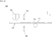
FIG. 1 is a schematic diagram showing a general electrode coating apparatus. - Referring to
FIG. 1 , a conventionalelectrode coating apparatus 1 includes a coating die 20. An electrode slurry is discharged from the coating die 20 and is coated on acurrent collector 10. At this time, thecoating die 20 has a slit-shaped discharge port in a width direction of thecurrent collector 10 so that the electrode slurry can be discharged. As thecurrent collector 10 is moved in one direction, the electrode slurry is consecutively coated or pattern-coated on thecurrent collector 10, thereby forming a coatedpart 11, on which an electrode slurry has been coated, or anon-coated part 12, on which the electrode slurry has not been coated. At this time, in order for the electrode to show the maximum performance, a lot of electrode active materials should be contained in a small space, and in order to enhance the charge and discharge efficiency with the same amount of active materials, the electrode slurry should be coated in the uniform thickness. Particularly, as the size of the coating die increases and the speed of the coating process increases in order to implement high quality and high efficiency products and enhance production efficiency, it has become more important for the amount of coating liquid discharged from the coating die to be constant throughout the entire coating die in the width direction. - However, the thickness of the center portion of the coated electrode slurry and the thickness of the edge portion of the electrode slurry become non-uniform due to the difference in the discharge pressure inside the coating die. Specifically, the thickness of the coated part at the coating start point may increase in the process in which the electrode slurry inside the coating die is discharged at the time of coating start as shown in
FIG. 1(a) . Further, the thickness at both ends in the width direction of the coated part may more increase than the central portion due to the difference in the discharge pressure of the central portion and the discharge pressure of both ends of the coating die as shown inFIG. 1(b) . This may interfere with implementation of a high quality electrode. - In the past, the defect was detected by measuring the weight of the electrode with respect to the coating quality of the electrode. As such, there was no method for managing the thickness defect of the edge portion of the coated electrode slurry.
- Hence, there is a need for a technology for measuring the thickness of the edge portion of the coated electrode slurry and controlling the thickness of the portion.
- The present invention is believed to solve at least some of the above problems. For example, an aspect of the present invention provides an electrode coating apparatus and method for measuring the thickness of the electrode slurry, particularly the thickness of the edge portion in real time, and controlling the coated amount of the electrode slurry according to the measurement result.
- An electrode coating apparatus according to the present invention includes: a coating die which coats an electrode slurry on one surface of a current collector; a thickness measuring sensor which is positioned to be spaced apart from the current collector by a predetermined interval and measures a thickness of the coated electrode slurry in real time; and a controller which controls a coated amount of the electrode slurry in real time according to a result of measuring the thickness.
- In a specific example, the thickness measuring sensor may measure a thickness of an edge portion of the coated electrode slurry.
- In one example, the coating die may pattern-coat the electrode slurry to allow a non-coated part and a coated part to be alternately formed along a coating direction.
- At this time, the thickness measuring sensor may be fixed at a central portion in a width direction of the current collector and measure a thickness of both edge portions (balcony portion) in the coating direction of the coated part.
- In another example, the coating die may consecutively coat the electrode slurry to allow a coated part to be consecutively formed along a coating direction.
- At this time, the thickness measuring sensor may measure a thickness of both edge portions (Fat Edge) in a width direction of the coated part while reciprocating in the width direction.
- In further another example, the apparatus may further include a drying unit which dries the coated electrode slurry.
- At this time, the thickness measuring sensor may be positioned at a coating start point and an exit point of the drying unit.
- In a specific example, the thickness measuring sensor may be a confocal sensor.
- In a specific example, the controller may control a discharge pressure of the coating die.
- Further, the present invention provides a electrode coating method. The method includes: preparing the above-described electrode coating apparatus; coating an electrode slurry on a current collector using a coating die; measuring a thickness of the coated electrode slurry in real time using a thickness measuring sensor; and controlling a coated amount of the electrode slurry in real time according to a result of measuring the thickness using a controller.
- In a specific example, the thickness measuring sensor may measure a thickness of an edge portion of the coated electrode slurry.
- In one example, the electrode slurry may be pattern-coated to allow a non-coated part and a coated part to be alternately formed along a coating direction.
- Herein, the thickness measuring sensor is fixed at a central portion in a width direction of the current collector and measures a thickness of a balcony portion which repeatedly shown according to movement of the current collector.
- In another example, the electrode slurry is consecutively coated along a coating direction.
- Herein, the thickness measuring sensor may measure a thickness of both edge portions in a width direction of the coated electrode slurry while reciprocating in the width direction.
- In a specific example, the coated amount of the electrode slurry may be controlled by adjustment of a discharge pressure of the coating die.
- According to the present invention, it is possible to recognize the thickness distribution of the electrode slurry in real time by measuring the thickness of the edge portion of the coated electrode slurry using the thickness measuring sensor on the transferred current collector, and accordingly, the thickness of the electrode slurry can be formed to be constant by adjusting the coated amount of the electrode slurry in real time.
-
-
FIG. 1 is a schematic diagram showing a general electrode coating apparatus. -
FIG. 2 is a block diagram showing a configuration of an electrode coating apparatus according to the present invention. -
FIGS. 3 to 5 are schematic diagrams illustrating an electrode coating apparatus according to an embodiment of the present invention. -
FIGS. 6 to 8 are schematic diagrams illustrating an electrode coating apparatus according to another embodiment of the present invention. -
FIG. 9 is a schematic diagram illustrating an electrode coating apparatus according to another embodiment of the present invention. -
FIG. 10 is a flowchart illustrating the order of an electrode coating method according to the present invention. -
FIGS. 11 and12 are graphs showing the thickness measurement results of an electrode slurry according to an embodiment of the present invention. - Hereinafter, the present invention will be described in detail with reference to the drawings. The terms and words used in the present specification and claims should not be construed as limited to ordinary or dictionary terms and the inventor may properly define the concept of the terms in order to best describe its invention. The terms and words should be construed as meaning and concept consistent with the technical idea of the present invention.
- In this application, it should be understood that terms such as "include" or "have" are intended to indicate that there is a feature, number, step, operation, component, part, or a combination thereof described on the specification, and they do not exclude in advance the possibility of the presence or addition of one or more other features or numbers, steps, operations, components, parts or combinations thereof. Also, when a portion such as a layer, a film, an area, a plate, etc. is referred to as being "on" another portion, this includes not only the case where the portion is "directly on" the another portion but also the case where further another portion is interposed therebetween. On the other hand, when a portion such as a layer, a film, an area, a plate, etc. is referred to as being "under" another portion, this includes not only the case where the portion is "directly under" the another portion but also the case where further another portion is interposed therebetween. In addition, to be disposed "on" in the present application may include the case disposed at the bottom as well as the top.
- In the present invention, the transfer direction of the current collector is a direction in which the electrode slurry is coated and means a direction (x-axis direction) in which the current collector is transferred. Further, the width direction is a direction indicated by the width of the current collector, and means a direction (y-axis direction) perpendicular to the direction in which the current collector is transferred on the plane represented by the current collector.
- Hereinafter, the present invention will be described in detail with reference to the drawings.
-
FIG. 2 is a block diagram showing a configuration of an electrode coating apparatus according to the present invention. - Referring to
FIG. 2 , anelectrode coating apparatus 100 according to the present invention includes: a coating die 120 which coats an electrode slurry on one surface of a current collector; athickness measuring sensor 130 which is positioned to be spaced apart from the current collector by a predetermined interval and measures a thickness of the coated electrode slurry in real time; and acontroller 140 which controls a coated amount of the electrode slurry in real time according to a result of measuring the thickness. - As described above, the thickness of the center portion of the coated electrode slurry and the thickness of the edge portion of the electrode slurry become non-uniform due to the difference in the discharge pressure inside the coating die, thereby deteriorating the quality of the electrode.
- According to the present invention, it is possible to recognize the thickness distribution of the electrode slurry in real time by measuring the thickness of the edge portion of the coated electrode slurry using the thickness measuring sensor on the transferred current collector, and accordingly, the thickness of the electrode slurry can be formed to be constant by adjusting the coated amount of the electrode slurry in real time.
-
FIGS. 3 to 5 are schematic diagrams illustrating an electrode coating apparatus according to an embodiment of the present invention.FIG. 4 is a side view ofFIG. 3 , andFIG. 5 is a top view ofFIG. 3 . - When referring to
FIGS. 3 to 5 together withFIG. 2 , anelectrode coating apparatus 100 according to the present invention includes a coating die 120 for coating an electrode slurry on one surface of acurrent collector 110. The coating die 120 may be positioned to be spaced apart from thecurrent collector 110 by a predetermined distance. The coating die 120 may pattern-coat an electrode slurry on thecurrent collector 110 as will be described later. - The coating die 120 may include a main body and a tip coupled to the main body. Specifically, a discharge path, on which the supplied electrode slurry may be moved, may be formed in the main body, and a discharge port, through which the electrode slurry is discharged, may be formed at the end of the tip. The discharge port may have a slit shape extended in the width direction along the end of the tip, and the thickness may be adjusted according to the thickness of the electrode slurry coated on the current collector. Further, the electrode slurry is stored in a separate slurry supply tank (not shown), and the electrode slurry may be supplied to the coating die through a supply pipe (not shown) connected to the coating die.
- Further, if a coating process is started in a state that the
current collector 110 is wound on a separate unwinding roll (not shown), the electrode slurry is coated while moving along a predetermined path. - The
current collector 110 may be positive electrode current collector or a negative electrode current collector, and the electrode slurry may contain an electrode active material. The electrode active material may be a positive electrode active material or a negative electrode active material. The electrode slurry may further contain a conductive material and a binder, and may be what is obtained by dispersing an electrode active material, a conductive material and a binder in a solvent. - In the present invention, the positive electrode current collector generally has a thickness of 3 to 500 micrometers. The positive electrode current collector is not particularly limited as long as it has high conductivity without causing a chemical change in the battery. Examples of the positive electrode current collector include stainless steel, aluminum, nickel, titanium, sintered carbon or aluminum or stainless steel of which the surface has been treated with carbon, nickel, titanium, silver, or the like. The current collector may have fine irregularities on the surface thereof to increase the adhesion of the positive electrode active material, and various forms such as a film, a sheet, a foil, a net, a porous body, a foam, and a nonwoven fabric are possible.
- The negative electrode current collector generally has a thickness of 3 to 500 micrometers. The negative electrode current collector is not particularly limited as long as it has electrical conductivity without causing chemical changes in the battery, and examples thereof include copper, stainless steel, aluminum, nickel, titanium, sintered carbon, copper or stainless steel of which the surface has been treated with carbon, nickel, titanium, silver or the like, aluminum-cadmium alloy, or the like. In addition, like the positive electrode current collector, fine unevenness can be formed on the surface to enhance the bonding force of the negative electrode active material, and it can be used in various forms such as a film, a sheet, a foil, a net, a porous body, a foam, and a nonwoven fabric.
- In the present invention, the positive electrode active material is a material capable of causing an electrochemical reaction and a lithium transition metal oxide, and contains two or more transition metals. Examples thereof include: layered compounds such as lithium cobalt oxide (LiCoO2) and lithium nickel oxide (LiNiO2) substituted with one or more transition metals; lithium manganese oxide substituted with one or more transition metals; lithium nickel oxide represented by the formula LiNi1-yMyO2 (wherein M = Co, Mn, Al, Cu, Fe, Mg, B, Cr, Zn or Ga and contains at least one of the above elements, 0.01 ≦ y ≦ 0.7); lithium nickel cobalt manganese composite oxide represented by the formula Li1+zNibMncCo1-(b+c+d)MdO(2-e)Ae such as Li1+zNi1/3CO1/3Mn1/3O2, Li1+zNi0.4Mn0.4Co0.2O2 etc. (wherein - 0.5≤z≤0.5, 0.1≤b≤0.8, 0.1≤c≤0.8, 0≤d≤0.2, 0≤e≤0.2, b+c+d<1, M = Al, Mg, Cr, Ti, Si or Y, and A = F, P or Cl); olivine-based lithium metal phosphate represented by the formula Li1+xM1-yM'yPO4-zXz (wherein M = transition metal, preferably Fe, Mn, Co or Ni, M'= Al, Mg or Ti, X = F, S or N, and -0.5≤x≤0.5, 0≤y≤0.5, 0≤z≤0.1).
- Examples of the negative electrode active material include carbon such as non-graphitized carbon and graphite carbon; metal complex oxide such as LixFe2O3(0≤x≤1), LixWO2(0≤x≤1), SnxMe1-xMe'yOz (Me: Mn, Fe, Pb, Ge; Me': Al, B, P, Si,
groups 1, 2, and 3 of the periodic table, halogen; 0<x≤1; 1≤y≤3; 1≤z≤8); lithium metal; lithium alloy; silicon alloy; tin alloy; metal oxides such as SnO, SnO2, PbO, PbO2, Pb2O3, Pb3O4, Sb2O3, Sb2O4, Sb2O5, GeO, GeO2, Bi2O3, Bi2O4, and Bi2O5; conductive polymers such as polyacetylene; and Li-Co-Ni-based materials. - The conductive material is usually added in an amount of 1 to 30% by weight based on the total weight of the mixture including the positive electrode active material. Such a conductive material is not particularly limited as long as it has electrical conductivity without causing a chemical change in the battery, and examples thereof include graphite such as natural graphite and artificial graphite; carbon black such as carbon black, acetylene black, Ketjen black, channel black, furnace black, lamp black, and summer black; conductive fibers such as carbon fiber and metal fiber; metal powders such as carbon fluoride, aluminum and nickel powder; conductive whiskey such as zinc oxide and potassium titanate; conductive metal oxides such as titanium oxide; and conductive materials such as polyphenylene derivatives and the like.
- The binder is added in an amount of 1 to 30% by weight, on the basis of the total weight of the mixture containing the positive electrode active material, as a component that assists in bonding between the active material and the conductive material and bonding to the current collector. Examples of such binders include polyvinylidene fluoride, polyvinyl alcohol, carboxymethylcellulose (CMC), starch, hydroxypropylcellulose, regenerated cellulose, polyvinylpyrrolidone, tetrafluoroethylene, polyethylene, polypropylene, ethyl ene-propylene-diene terpolymer (EPDM), sulfonated EPDM, styrene butylene rubber, fluorine rubber, various copolymers and the like.
- The type of the solvent is not particularly limited as long as it is capable of dispersing an electrode active material, and either an aqueous solvent or a non-aqueous solvent may be used. For example, the solvent may be a solvent generally used in the art, such as dimethyl sulfoxide (DMSO), isopropyl alcohol, N-methylpyrrolidone (NMP), acetone, or water, and one of them alone or a mixture of two or more may be used. The amount of the solvent used may be such that the slurry can be adjusted to have an appropriate viscosity in consideration of the coating thickness, production yield, and workability of the slurry, and is not particularly limited.
- The
thickness measuring sensor 130 is positioned to be spaced apart from thecurrent collector 110 by a predetermined distance and measures the thickness of the coated electrode slurry, that is the thickness of thecoated part 111 in real time. Particularly, thethickness measuring sensor 130 recognizes the difference in the thickness of the edge portion by measuring the edge portion of the coated electrode slurry (coated part) and comparing it with the central portion where the thickness is constantly maintained. Further, in the present invention, measuring the edge portion by thethickness measuring sensor 130 means centering on measuring the thickness of the edge portion, and it does not exclude measuring the thickness of the center portion of the coated electrode slurry. In the present invention, as thecurrent collector 110 is moved, thethickness measuring sensor 130 measures the thickness of the coated electrode slurry (coated part) in real time, and in the process, both the thickness of the edge portion and the thickness of the central portion of the coated electrode slurry (coated part) may be measured. It is possible to calculate the thickness deviation between the two portions from result of measuring the thickness of the edge portion and the thickness of the central portion, which can be utilized in controlling the thickness deviation. - At this time, the
thickness measuring sensor 130 includes a probe for measuring the thickness, and each probe may be positioned at the upper surface and the lower surface of thecurrent collector 110 respecitvely. When a plurality of thickness measuring sensors are positioned along a width direction, the thickness measuring sensors may interfere with each other. - Specifically, the
thickness measuring sensor 130 may use a different thickness measuring scheme according to the coating scheme of the electrode slurry. - Referring to
FIGS. 3 to 5 , the coating die 120 may pattern-coat an electrode slurry. In this case, the coating die 120 may repeat the discharge and stop of the electrode slurry during the movement of thecurrent collector 110. Alternatively, in a state that the current collector has been stopped, it is possible to repeat the discharge and stop of the electrode slurry while the coating die is moved on the current collector. However, in the roll-to-roll process, it may be more efficient for the current collector to be moved in a state that the coating die has been stopped. - Likewise, as the coating die 120 pattern-coats the electrode slurry, a
coated part 111, on which an electrode slurry has been coated along the coating direction, and anon-coated part 112, on which the electrode slurry has not been coated, are alternately formed on thecurrent collector 110. Namely, in this case, a balcony portion A is repeatedly formed along a coating direction. Herein, the balcony portion A is a boundary portion of thecoated part 111 and thenon-coated part 112 which are alternately formed in the coating direction, and means the edge portion in the coating direction of the coated part (coated electrode slurry). - Likewise, when the electrode slurry is pattern-coated, the
thickness measuring sensor 130 measures the thickness of the balcony portion. Specifically, thethickness measuring sensor 130 may be fixed at a central portion in a width direction of thecurrent collector 110 and measure a thickness of both edge portions (balcony portion) in a coating direction of thecoated part 111. As described above, since the portion, where the thickness of the electrode slurry coated based on the width direction of thecurrent collector 110 is most constant, is the center portion of thecurrent collector 110, thethickness measuring sensor 130 is positioned at the center portion of thecurrent collector 110, where the thickness of the balcony portion can be most accurately measured. -
FIGS. 6 to 8 are schematic diagrams illustrating an electrode coating apparatus according to an embodiment of the present invention.FIG. 7 is a side view ofFIG. 6 , andFIG. 8 is a top view ofFIG. 6 . - When referring to
FIGS. 6 to 8 together withFIG. 2 , anelectrode coating apparatus 200 according to the present invention includes a coating die 220 for coating an electrode slurry on one surface of acurrent collector 210. The coating die 220 may be positioned to be spaced apart from thecurrent collector 210 by a predetermined distance. The coating die 220 may consecutively coat an electrode slurry on thecurrent collector 210 as will be described later. - The coating die 220 may include a main body and a tip coupled to the main body. Specifically, a discharge path, on which the supplied electrode slurry may be moved, may be formed at the main body, and a discharge port, through which the electrode slurry is discharged, may be formed in the end of the tip. The discharge port may have a slit shape extended in the width direction along the end of the tip, and the thickness may be adjusted according to the thickness of the electrode slurry coated on the current collector. Further, the electrode slurry is stored in a separate slurry supply tank (not shown), and the electrode slurry may be supplied to the coating die through a supply pipe (not shown) connected to the coating die.
- If a coating process is started in a state that the
current collector 210 is wound on a separate unwinding roll (not shown), the electrode slurry is coated while moving along a predetermined path. - The
thickness measuring sensor 230 is positioned to be spaced apart from thecurrent collector 210 by a predetermined distance and measures the thickness of the coated electrode slurry (coated part) in real time. Particularly, thethickness measuring sensor 230 recognizes the difference in the thickness of the edge portion by measuring the edge portion of the coated electrode slurry (coated part) and comparing it with the central portion where the thickness is constantly maintained. - At this time, the coating die 220 may consecutively coat an electrode slurry on the
current collector 210. In this case, the coating die 220 does not stop the discharge of the electrode slurry during the movement of thecurrent collector 210. Likewise, as the coating die 220 consecutively coats the electrode slurry, thecoated part 211, on which an electrode slurry has been coated along the coating direction, is consecutively formed on thecurrent collector 210. Thenon-coated part 212 may be formed at a portion adjacent to the coated part in a width direction. Namely, in such a case, a balcony portion is not formed except for the coating start point and the coating end point. Hence, in this case, thethickness measuring sensor 230 measures the thickness of both edge portions (Fat Edge, B and B') in the width direction of thecoated part 211. - In the present invention, a
non-coated part 212 is formed at both ends in the width direction of thecurrent collector 210 for formation of an electrode tab. Namely, thenon-coated part 212 is also consecutively extended in the coating direction as the electrode slurry is consecutively coated. Thethickness measuring sensor 230 measures a thickness of both edge portions (B) in a width direction of thecoated part 211 while reciprocating in the width direction. Specifically, referring toFIG. 8 , if thethickness measuring sensor 230 is moved to the left and reaches the edge portion in the width direction of thecoated part 211 in a state that thecurrent collector 210 is moving, the thickness is measured, and thethickness measuring sensor 230 is then moved to the right and reaches the edge portion B' at the opposite side of thecoated part 211 to thereby measure the thickness. Thethickness measuring sensor 230 measures the thickness by repeating the cycle during the movement of thecurrent collector 210. Likewise, as thethickness measuring sensor 230 reciprocates in the width direction, thethickness measuring sensor 230 shows the path in the zigzag form based on thecurrent collector 210. - Likewise, in the present invention, the thickness measuring sensor is not positioned at each of both ends in the width direction of the coated electrode slurry, and the thickness measuring sensor may measure a thickness of both edge portions in a width direction of the coated electrode slurry while reciprocating in the width direction in order to prevent interference between thickness measuring sensors.
- Further, there is no particular limitation on the type of the thickness measuring sensor as long as it can measure the thickness of the electrode slurry coated on the current collector. For example, the thickness measuring sensor may be a confocal sensor.
- The confocal sensor may detect light generated by fluorescence very close to the measurement object on the focal plane.
- Specifically, the confocal sensor is optically focused on the measurement object of the electrode slurry. Thereafter, the light from the laser is converged through the object lens of the confocal sensor and is incident on the optical focal point of the measurement object portion. At this time, the scattering light scattered in the measurement object portion exposed to light from the laser again pass through the object lens, and only accurately focused light is separated through the aperture. The spectrum of light passing through the aperture is digitally signaled in the detector, which is then analyzed by wavelengths to thereby measure the thickness of the electrode slurry.
- Since such a confocal sensor disperses the light source and the array according to the wavelength of the color is converted into the distance, the thickness of the electrode slurry can be accurately measured. Further, since the thickness of the electrode slurry is measured using light, the thickness of the desired portion can be accurately measured even if the current collector is moved in a high speed as compared to other measurement methods such as eddy current.
- Likewise, when the thickness of the electrode slurry is measured, the thickness measurement result is transmitted to the controller. The controller controls the coated amount of the electrode slurry in real time by reflecting the thickness measurement result. There is no particular limitation on the method of controlling the coated amount of the electrode slurry, but it is possible to install a valve which directly adjusts the flow rate of the electrode slurry to the slurry supply pipe, through which an electrode slurry is supplied to the coating die, and control the opening and closing level of the valve. In this case, since the coated amount may be intuitively controlled, the thickness may be easily adjusted. Further, the slurry supply pipe has a plurality of branches in order to adjust the coated amount according to the width direction, and the valve may be installed for each branch. In this case, each valve may independently operate to control the coated amount of the electrode slurry. For example, when the thickness in the width direction of the edge portion is greater than that of other portions, it is possible to reduce the amount of slurry supplied to the edge portion in the width direction by closing the nozzle of the portion to which the slurry is supplied.
-
FIG. 9 is a schematic diagram illustrating an electrode coating apparatus according to another embodiment of the present invention. - Referring to
FIG. 9 , anelectrode coating apparatus 300 further includes adrying unit 340 which dries a coated electrode slurry. - The drying
unit 340 has a chamber shape where a space for drying an electrode slurry (not shown) coated on thecurrent collector 310 is formed and includes a heat source for drying the electrode slurry. For example, the dryingunit 340 may be an oven. Further, the heat source may be a hot air nozzle or an infrared heater. The heat source can be arranged at regular intervals along a transfer direction of thecurrent collector 310, and hot air or infrared ray may be supplied in a direction perpendicular to thecurrent collector 310. Further, the dryingunit 340 may be divided into a plurality of drying zones. - The hot air nozzle includes a main body unit and an injection unit. The main body unit constitutes the body of the hot air nozzle, and fixes the hot air nozzle to the ceiling of the oven. In addition, the main body unit is empty inside and transmits hot air transmitted from a hot air supply source (not shown) to the injection unit. On the other hand, the injection unit is provided on the lower surface of the main body unit. The injection unit communicates with the main body unit, and an injection hole portion through which hot air is injected is formed on the lower surface of the injection unit. The injection hole portion may have a structure in which a plurality of pores are arranged at regular intervals.
- Further, the infrared heater may include an infrared lamp that irradiates infrared rays to the electrode and a cradle that supports or mounts the infrared lamp. The shape of the infrared lamp is not particularly limited, and for example, the rod-shaped lamp may be arranged in parallel along the transfer direction of the electrode while extending in the width direction of the electrode. Details about other drying units are known to those of ordinary skill in the art, and thus the detailed description thereof is omitted here.
- Referring to
FIG. 9 , thecurrent collector 310, where an electrode slurry has been coated on one surface, enters into thedrying unit 340 and is then dried. Thereafter, after one dried surface is turned upside down toward the ground, an electrode slurry is coated on the opposite surface of the surface, where an electrode slurry has been applied, is then dried. This is to prevent the coated electrode slurry from flowing down by gravity. - At this time, the
thickness measuring sensor 330 is positioned at a coating start point and an exit point of thedrying unit 340. InFIG. 9 , since the coating and drying of the electrode slurry are performed twice on one surface and the other surface of thecurrent collector 310, thethickness measuring sensor 330 may also be positioned at each coating start point and the exit point of thedrying unit 340, respectively. Namely, the thickness measuring may be performed a total of 4 times. Likewise, it is possible to compare the thickness of the electrode slurry before drying with the thickness of the electrode slurry after drying by measuring the thickness of the electrode slurry right after the coating of the electrode slurry and right after the drying of the electrode slurry. - Further, the present invention provides a method for coating an electrode by using the above described electrode coating apparatus.
-
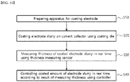
FIG. 10 is a flowchart illustrating the order of an electrode coating method according to the present invention. - Referring to
FIG. 10 , an electrode coating method according to the present invention includes: preparing the above-described electrode coating apparatus (S10); coating an electrode slurry on a current collector using a coating die (S20); measuring a thickness of the coated electrode slurry in real time using a thickness measuring sensor (S30); and controlling a coated amount of the electrode slurry in real time according to a result of measuring the thickness using a controller (S40). - First, an electrode slurry containing an electrode active material is coated on a current collector. The configuration about the current collector and the electrode slurry has already been described above.
- When the electrode slurry is applied, the thickness of the coated electrode slurry is measured using the thickness measuring sensor. At this time, the thickness measuring sensor measures the thickness of the edge portion of the coated electrode slurry (coated part).
- At this time, when the electrode slurry is pattern-coated to allow a non-coated part and a coated part to be alternately formed along a coating direction, the thickness measuring sensor is fixed at a central portion in a width direction of the current collector and measures a thickness of a balcony portion which repeatedly shown according to movement of the current collector. The details about the balcony portion are described above. In this process, it is possible to recognize the difference between the thickness of the balcony portion and the thickness of the center portion of the coated electrode slurry.
- Further, when the electrode slurry is consecutively coated along the coating direction, a balcony portion is not formed. At this time, the thickness measuring sensor measures the thickness of both edge portions in a width direction of the coated electrode slurry (coated part) while reciprocating in the width direction. In this process, it is possible to recognize the difference between the thickness of the center portion in the width direction and the thicknessof the edge portion in the width direction.
- When the thickness of the coated electrode slurry is measured, the thickness measurement result is reflected through the controller, thereby controlling the coated amount of the electrode slurry in real time. The coated amount of the electrode slurry can be controlled through adjustment of the discharge pressure of the coating die, and, for example, may be controlled through the opening and closing of the valve installed at the pipe through which a slurry is supplied.
- Further, the electrode coating method according to the present invention includes drying an electrode slurry. At this time, the measuring of the thickness may be performed right after coating the electrode slurry or right after drying the electrode slurry.
- Likewise, according to the present invention, it is possible to recognize the thickness distribution of the electrode slurry in real time by measuring the thickness of the edge portion of the coated electrode slurry using the thickness measuring sensor on the transferred current collector, and accordingly, the thickness of the electrode slurry can be formed to be constant by adjusting the coated amount of the electrode slurry in real time.
- 85wt% of graphite and 9.5wt% of SiO as the negative electrode active material, 1.4wt% of Denka black as the conductive material, 3.0wt% of SBR as the binder, and 1.1 wt% of CMC as the thickener were added to water to thereby prepare a negative electrode slurry.
- The negative electrode slurry was coated on a copper current collector having a thickness of 8µm using an electrode coating apparatus including a coating die, a thickness measuring sensor and a drying unit as shown in
FIGS. 3 and9 . Specifically, the negative electrode slurry was coated on the current collector to allow a non-coated part and a coated part to be alternately formed. - At this time, the thickness of the negative electrode slurry (coated part) in the coating direction was measured while moving the current collector in a state that allows the thickness measuring sensor to be positioned at the center in the width direction of the current collector. The thickness of the negative electrode slurry was measured one time right after the coating process and right after the drying process, respectively. At this time, the thickness of the negative electrode slurry was measured using a confocal sensor. A known sensor such as Confocal DT of KAIS company may be used as the confocal sensor. The results are shown in
FIG. 11 . InFIG. 11 , the horizontal axis represents the distance between the thickness measurement point and the original point based on the assumption that the coating start point is the original point, and the vertical axis represents the thickness of the coated electrode slurry at the measurement point. Further, the wet thickness means the thickness of a slurry right after coated by a coating die, and the dry thickness means the thickness after the drying process. - 85wt% of graphite and 9.5wt% of SiO as the negative electrode active material, 1.4wt% of Denka black as the conductive material, 3.0wt% of SBR as the binder, and 1.1 wt% of CMC as the thickener were added to water to thereby prepare a negative electrode slurry.
- The negative electrode slurry was coated on a copper current collector having a thickness of 8um using an electrode coating apparatus including a coating die, a thickness measuring sensor and a drying unit as shown in
FIGS. 6 and9 . Specifically, the negative electrode slurry was consecutively coated on the current collector using a coating die. - At this time, the thickness in the width direction of the negative electrode slurry was measured while the thickness measuring sensor is reciprocated in the width direction of the current collector. The thickness of the negative electrode slurry was measured one time right after the coating process and right after the drying process, respectively. The results are shown in
FIG. 12 . InFIG. 12 , the horizontal axis represents the distance between the measurement point and the original point based on the assumption that one end in the width direction of the current collector is the original point, and the vertical axis represents the thickness of the coated electrode slurry at the measurement point. Further, the wet thickness means the thickness of a slurry right after coated by a coating die, and the dry thickness means the thickness after the drying process. - Referring to
FIGS. 11 and12 , the electrode coating apparatus according to the present invention can measure the thickness of the coated slurry in real time. - Specifically, referring to
FIG. 11 , a peak is shown at the edge portion (balcony portion) in the coating direction of the coated electrode slurry (coated part). Likewise, referring toFIG. 12 , a peak is shown at the edge portion in the width direction of the coated electrode slurry (coated part). Likewise, according to the present invention, it is possible to recognize the thickness distribution of the electrode slurry in real time by measuring the thickness of the edge portion of the coated electrode slurry using the thickness measuring sensor, and accordingly, the thickness of the electrode can be formed to be constant by adjusting the thickness of the electrode slurry in real time. - Further, according to the present invention, it is possible to compare the thickness of the electrode slurry before drying with the thickness of the electrode slurry after drying by measuring the thickness of the electrode slurry right after the coating of the electrode slurry and right after the drying of the electrode slurry.
- The above description is merely illustrative of the technical idea of the present invention, and those skilled in the art to which the present invention pertains may make various modifications and variations without departing from the essential characteristics of the present invention. Therefore, the drawings disclosed in the present invention are not intended to limit the technical idea of the present invention but to describe the present invention, and the scope of the technical idea of the present invention is not limited by these drawings. The scope of protection of the present invention should be interpreted by the following claims, and all technical ideas within the scope equivalent thereto should be construed as being included in the scope of the present invention.
- On the other hand, in this specification, terms indicating directions such as up, down, left, right, before, and after are used, but it is obvious that these terms are for convenience of description only and may change depending on the location of the object or the location of the observer.
-
- 1, 100, 200, 300: electrode coating apparatus
- 10, 110, 210, 310: current collector
- 11, 111, 211: coated part
- 12, 112, 212: non-coated part
- 20, 120, 220, 320: coating die
- 130, 230, 330: thickness measuring sensor
- 140: controller
- 340: drying unit
Claims (17)
- An electrode coating apparatus, the apparatus comprising:a coating die which coats an electrode slurry on one surface of a current collector;a thickness measuring sensor which is positioned to be spaced apart from the current collector by a predetermined interval and measures a thickness of the coated electrode slurry in real time; anda controller which controls a coated amount of the electrode slurry in real time according to a result of measuring the thickness.
- The electrode coating apparatus of claim 1, wherein the thickness measuring sensor measures a thickness of an edge portion of the coated electrode slurry.
- The electrode coating apparatus of claim 1, wherein the coating die pattern-coats the electrode slurry to allow a non-coated part and a coated part to be alternately formed along a coating direction.
- The electrode coating apparatus of claim 3, wherein the thickness measuring sensor is fixed at a central portion in a width direction of the current collector and measures a thickness of both edge portions in the coating direction of the coated part.
- The electrode coating apparatus of claim 1, wherein the coating die consecutively coats the electrode slurry to allow a coated part to be consecutively formed along a coating direction.
- The electrode coating apparatus of claim 5, wherein the thickness measuring sensor measures a thickness of both edge portions (Fat Edge) in a width direction of the coated part while reciprocating in the width direction.
- The electrode coating apparatus of claim 1, further comprising a drying unit which dries the coated electrode slurry.
- The electrode coating apparatus of claim 7, wherein the thickness measuring sensor is positioned at a coating start point and an exit point of the drying unit.
- The electrode coating apparatus of claim 1, wherein the thickness measuring sensor is a confocal sensor.
- The electrode coating apparatus of claim 1, wherein the controller controls a discharge pressure of the coating die.
- A electrode coating method, the method comprising:preparing an electrode coating apparatus according to claim 1;coating an electrode slurry on a current collector using a coating die;measuring a thickness of the coated electrode slurry in real time using a thickness measuring sensor; andcontrolling a coated amount of the electrode slurry in real time according to a result of measuring the thickness using a controller.
- The electrode coating method of claim 11, wherein the thickness measuring sensor measures a thickness of an edge portion of the coated electrode slurry.
- The electrode coating method of claim 11, wherein the electrode slurry is pattern-coated to allow a non-coated part and a coated part to be alternately formed along a coating direction.
- The electrode coating method of claim 13, wherein the thickness measuring sensor is fixed at a central portion in a width direction of the current collector and measures a thickness of a balcony portion which repeatedly shown according to movement of the current collector.
- The electrode coating method of claim 11, wherein the electrode slurry is consecutively coated along a coating direction.
- The electrode coating method of claim 15, wherein the thickness measuring sensor measures a thickness of both edge portions in a width direction of the coated electrode slurry while reciprocating in the width direction.
- The electrode coating method of claim 11, wherein the coated amount of the electrode slurry is controlled by adjustment of a discharge pressure of the coating die.
Applications Claiming Priority (2)
| Application Number | Priority Date | Filing Date | Title |
|---|---|---|---|
| KR1020200149164A KR20220063383A (en) | 2020-11-10 | 2020-11-10 | Electrode coating device and coating method |
| PCT/KR2021/015920 WO2022103072A1 (en) | 2020-11-10 | 2021-11-04 | Electrode coating device and electrode coating method |
Publications (2)
| Publication Number | Publication Date |
|---|---|
| EP4101547A1 true EP4101547A1 (en) | 2022-12-14 |
| EP4101547A4 EP4101547A4 (en) | 2023-10-11 |
Family
ID=81601516
Family Applications (1)
| Application Number | Title | Priority Date | Filing Date |
|---|---|---|---|
| EP21892240.9A Pending EP4101547A4 (en) | 2020-11-10 | 2021-11-04 | Electrode coating device and electrode coating method |
Country Status (5)
| Country | Link |
|---|---|
| US (1) | US20230110084A1 (en) |
| EP (1) | EP4101547A4 (en) |
| KR (1) | KR20220063383A (en) |
| CN (1) | CN115175771B (en) |
| WO (1) | WO2022103072A1 (en) |
Families Citing this family (1)
| Publication number | Priority date | Publication date | Assignee | Title |
|---|---|---|---|---|
| CN215465733U (en) * | 2021-07-30 | 2022-01-11 | 宁德时代新能源科技股份有限公司 | Coating equipment |
Family Cites Families (11)
| Publication number | Priority date | Publication date | Assignee | Title |
|---|---|---|---|---|
| JP3680985B2 (en) * | 1999-06-11 | 2005-08-10 | トヨタ自動車株式会社 | Method for manufacturing battery sheet electrode |
| KR101145840B1 (en) | 2009-12-24 | 2012-05-17 | 씨아이에스(주) | Automatic amending apparatus for winding thickness of battery sheet, Winding apparatus for secondary battery includig the same, and automatic amendig method there of |
| KR101243573B1 (en) * | 2011-02-18 | 2013-03-20 | 삼성에스디아이 주식회사 | Apparatus and method for coating active material |
| US9677279B2 (en) * | 2011-04-14 | 2017-06-13 | T&M Inventions, Llc | Condensation control in a roof mounted load support structure |
| DE102012224228A1 (en) * | 2012-12-21 | 2014-06-26 | Robert Bosch Gmbh | Method for wet coating of substrate used in manufacture of lithium-ion battery cell, involves measuring layer thicknesses of coating layer on substrate, and independently regulating pressure in each of the first nozzle by second nozzle |
| JP5411371B1 (en) * | 2013-02-21 | 2014-02-12 | 株式会社日立パワーソリューションズ | Roll press equipment and thickness measurement system |
| KR101739175B1 (en) * | 2013-04-26 | 2017-05-23 | 요코가와 덴키 가부시키가이샤 | Control system and control method |
| JP2015013248A (en) * | 2013-07-04 | 2015-01-22 | 株式会社豊田自動織機 | Coating device and electrode manufacturing method |
| JP6422711B2 (en) * | 2013-10-11 | 2018-11-14 | 東レエンジニアリング株式会社 | Battery electrode plate manufacturing apparatus and method |
| KR20150061593A (en) * | 2013-11-27 | 2015-06-04 | 시바우라 메카트로닉스 가부시끼가이샤 | Applicator, application method, appratus and method for manufacturing a display device member |
| JP6344313B2 (en) * | 2015-06-03 | 2018-06-20 | トヨタ自動車株式会社 | Coating film width measuring method and coating film width measuring apparatus |
-
2020
- 2020-11-10 KR KR1020200149164A patent/KR20220063383A/en not_active Application Discontinuation
-
2021
- 2021-11-04 WO PCT/KR2021/015920 patent/WO2022103072A1/en unknown
- 2021-11-04 CN CN202180016994.4A patent/CN115175771B/en active Active
- 2021-11-04 US US17/908,651 patent/US20230110084A1/en active Pending
- 2021-11-04 EP EP21892240.9A patent/EP4101547A4/en active Pending
Also Published As
| Publication number | Publication date |
|---|---|
| WO2022103072A1 (en) | 2022-05-19 |
| US20230110084A1 (en) | 2023-04-13 |
| KR20220063383A (en) | 2022-05-17 |
| EP4101547A4 (en) | 2023-10-11 |
| CN115175771B (en) | 2023-12-29 |
| CN115175771A (en) | 2022-10-11 |
Similar Documents
| Publication | Publication Date | Title |
|---|---|---|
| US20120219841A1 (en) | Lithium ion cell design apparatus and method | |
| US20120082884A1 (en) | Electrospinning for integrated separator for lithium-ion batteries | |
| KR20220030745A (en) | Device for drying the electrode and method for drying the electrode | |
| EP4101547A1 (en) | Electrode coating device and electrode coating method | |
| EP4067920A1 (en) | Apparatus for measuring battery cell capacity and method for measuring battery cell capacity | |
| KR20140029799A (en) | Fabricating method and device of seperator and electrochemical cell having the same seperator | |
| JP2020155335A (en) | Secondary cell | |
| KR20220009095A (en) | Drying apparatus and manufacturing apparatus for electrode comprising the same | |
| Wu et al. | Preparation and characterization of LiMn 2 O 4/Li 1.3 Al 0.3 Ti 1.7 (PO 4) 3/LiMn 2 O 4 thin-film battery by spray technique | |
| KR20220128304A (en) | Electrode, and Method for Preparing the same | |
| US20230143349A1 (en) | Electrode Drying System and Electrode Drying Method | |
| EP4109580A1 (en) | Automatic electrode drying control system and automatic electrode drying control method | |
| EP4106041A1 (en) | Electrode drying system and electrode drying method | |
| EP4084112A1 (en) | Electrode drying device and electrode drying method | |
| US20230121300A1 (en) | Electrode Slurry Coating Apparatus and Method Capable of Measuring Remaining Oil Level | |
| US20220140309A1 (en) | Method of Rolling Electrode | |
| KR20220067263A (en) | Device for drying electrode compring humidifying part | |
| KR20220102959A (en) | Method and device for evaluating core deformation degree of cylindrical battery cell | |
| KR20220057303A (en) | Electrode manufacturing apparatus including coating guide | |
| US20220344630A1 (en) | Rolling Method For Electrode | |
| EP4258376A1 (en) | Electrode sheet drying device capable of preventing thermal wrinkles in uncoated portion | |
| KR20230067927A (en) | Electrode drying device that can prevent thermal wrinkles in the non-coated portion | |
| KR20230070859A (en) | Manufacturing method of electrode for lithium secondary batterry, apparatus for manufacturing electrode for lithium secondary batterry, electrode for lithium secondary batterry, and lithium secondary batterry comprising same | |
| Clara et al. | c12) Patent Application Publication |
Legal Events
| Date | Code | Title | Description |
|---|---|---|---|
| STAA | Information on the status of an ep patent application or granted ep patent |
Free format text: STATUS: THE INTERNATIONAL PUBLICATION HAS BEEN MADE |
|
| PUAI | Public reference made under article 153(3) epc to a published international application that has entered the european phase |
Free format text: ORIGINAL CODE: 0009012 |
|
| STAA | Information on the status of an ep patent application or granted ep patent |
Free format text: STATUS: REQUEST FOR EXAMINATION WAS MADE |
|
| 17P | Request for examination filed |
Effective date: 20220905 |
|
| AK | Designated contracting states |
Kind code of ref document: A1 Designated state(s): AL AT BE BG CH CY CZ DE DK EE ES FI FR GB GR HR HU IE IS IT LI LT LU LV MC MK MT NL NO PL PT RO RS SE SI SK SM TR |
|
| A4 | Supplementary search report drawn up and despatched |
Effective date: 20230911 |
|
| RIC1 | Information provided on ipc code assigned before grant |
Ipc: B05C 9/14 20060101ALI20230905BHEP Ipc: B05D 1/26 20060101ALI20230905BHEP Ipc: H01M 4/04 20060101ALI20230905BHEP Ipc: B05C 5/02 20060101AFI20230905BHEP |
|
| DAV | Request for validation of the european patent (deleted) | ||
| DAX | Request for extension of the european patent (deleted) |