EP4101418B1 - System zur herstellung einer orthodontischen vorrichtung - Google Patents
System zur herstellung einer orthodontischen vorrichtung Download PDFInfo
- Publication number
- EP4101418B1 EP4101418B1 EP22175789.1A EP22175789A EP4101418B1 EP 4101418 B1 EP4101418 B1 EP 4101418B1 EP 22175789 A EP22175789 A EP 22175789A EP 4101418 B1 EP4101418 B1 EP 4101418B1
- Authority
- EP
- European Patent Office
- Prior art keywords
- image
- reference model
- updated
- acquisition
- teeth
- Prior art date
- Legal status (The legal status is an assumption and is not a legal conclusion. Google has not performed a legal analysis and makes no representation as to the accuracy of the status listed.)
- Active
Links
Images


Classifications
-
- A—HUMAN NECESSITIES
- A61—MEDICAL OR VETERINARY SCIENCE; HYGIENE
- A61C—DENTISTRY; APPARATUS OR METHODS FOR ORAL OR DENTAL HYGIENE
- A61C7/00—Orthodontics, i.e. obtaining or maintaining the desired position of teeth, e.g. by straightening, evening, regulating, separating, or by correcting malocclusions
- A61C7/08—Mouthpiece-type retainers or positioners, e.g. for both the lower and upper arch
-
- A—HUMAN NECESSITIES
- A61—MEDICAL OR VETERINARY SCIENCE; HYGIENE
- A61C—DENTISTRY; APPARATUS OR METHODS FOR ORAL OR DENTAL HYGIENE
- A61C7/00—Orthodontics, i.e. obtaining or maintaining the desired position of teeth, e.g. by straightening, evening, regulating, separating, or by correcting malocclusions
- A61C7/002—Orthodontic computer assisted systems
-
- A—HUMAN NECESSITIES
- A61—MEDICAL OR VETERINARY SCIENCE; HYGIENE
- A61C—DENTISTRY; APPARATUS OR METHODS FOR ORAL OR DENTAL HYGIENE
- A61C9/00—Impression cups, i.e. impression trays; Impression methods
- A61C9/004—Means or methods for taking digitized impressions
- A61C9/0046—Data acquisition means or methods
- A61C9/0053—Optical means or methods, e.g. scanning the teeth by a laser or light beam
-
- G—PHYSICS
- G06—COMPUTING OR CALCULATING; COUNTING
- G06T—IMAGE DATA PROCESSING OR GENERATION, IN GENERAL
- G06T17/00—Three dimensional [3D] modelling, e.g. data description of 3D objects
-
- G—PHYSICS
- G06—COMPUTING OR CALCULATING; COUNTING
- G06T—IMAGE DATA PROCESSING OR GENERATION, IN GENERAL
- G06T7/00—Image analysis
- G06T7/20—Analysis of motion
- G06T7/254—Analysis of motion involving subtraction of images
-
- G—PHYSICS
- G16—INFORMATION AND COMMUNICATION TECHNOLOGY [ICT] SPECIALLY ADAPTED FOR SPECIFIC APPLICATION FIELDS
- G16H—HEALTHCARE INFORMATICS, i.e. INFORMATION AND COMMUNICATION TECHNOLOGY [ICT] SPECIALLY ADAPTED FOR THE HANDLING OR PROCESSING OF MEDICAL OR HEALTHCARE DATA
- G16H15/00—ICT specially adapted for medical reports, e.g. generation or transmission thereof
-
- G—PHYSICS
- G16—INFORMATION AND COMMUNICATION TECHNOLOGY [ICT] SPECIALLY ADAPTED FOR SPECIFIC APPLICATION FIELDS
- G16H—HEALTHCARE INFORMATICS, i.e. INFORMATION AND COMMUNICATION TECHNOLOGY [ICT] SPECIALLY ADAPTED FOR THE HANDLING OR PROCESSING OF MEDICAL OR HEALTHCARE DATA
- G16H30/00—ICT specially adapted for the handling or processing of medical images
- G16H30/20—ICT specially adapted for the handling or processing of medical images for handling medical images, e.g. DICOM, HL7 or PACS
-
- G—PHYSICS
- G16—INFORMATION AND COMMUNICATION TECHNOLOGY [ICT] SPECIALLY ADAPTED FOR SPECIFIC APPLICATION FIELDS
- G16H—HEALTHCARE INFORMATICS, i.e. INFORMATION AND COMMUNICATION TECHNOLOGY [ICT] SPECIALLY ADAPTED FOR THE HANDLING OR PROCESSING OF MEDICAL OR HEALTHCARE DATA
- G16H30/00—ICT specially adapted for the handling or processing of medical images
- G16H30/40—ICT specially adapted for the handling or processing of medical images for processing medical images, e.g. editing
-
- G—PHYSICS
- G16—INFORMATION AND COMMUNICATION TECHNOLOGY [ICT] SPECIALLY ADAPTED FOR SPECIFIC APPLICATION FIELDS
- G16H—HEALTHCARE INFORMATICS, i.e. INFORMATION AND COMMUNICATION TECHNOLOGY [ICT] SPECIALLY ADAPTED FOR THE HANDLING OR PROCESSING OF MEDICAL OR HEALTHCARE DATA
- G16H50/00—ICT specially adapted for medical diagnosis, medical simulation or medical data mining; ICT specially adapted for detecting, monitoring or modelling epidemics or pandemics
- G16H50/20—ICT specially adapted for medical diagnosis, medical simulation or medical data mining; ICT specially adapted for detecting, monitoring or modelling epidemics or pandemics for computer-aided diagnosis, e.g. based on medical expert systems
-
- G—PHYSICS
- G16—INFORMATION AND COMMUNICATION TECHNOLOGY [ICT] SPECIALLY ADAPTED FOR SPECIFIC APPLICATION FIELDS
- G16H—HEALTHCARE INFORMATICS, i.e. INFORMATION AND COMMUNICATION TECHNOLOGY [ICT] SPECIALLY ADAPTED FOR THE HANDLING OR PROCESSING OF MEDICAL OR HEALTHCARE DATA
- G16H50/00—ICT specially adapted for medical diagnosis, medical simulation or medical data mining; ICT specially adapted for detecting, monitoring or modelling epidemics or pandemics
- G16H50/50—ICT specially adapted for medical diagnosis, medical simulation or medical data mining; ICT specially adapted for detecting, monitoring or modelling epidemics or pandemics for simulation or modelling of medical disorders
-
- G—PHYSICS
- G16—INFORMATION AND COMMUNICATION TECHNOLOGY [ICT] SPECIALLY ADAPTED FOR SPECIFIC APPLICATION FIELDS
- G16H—HEALTHCARE INFORMATICS, i.e. INFORMATION AND COMMUNICATION TECHNOLOGY [ICT] SPECIALLY ADAPTED FOR THE HANDLING OR PROCESSING OF MEDICAL OR HEALTHCARE DATA
- G16H50/00—ICT specially adapted for medical diagnosis, medical simulation or medical data mining; ICT specially adapted for detecting, monitoring or modelling epidemics or pandemics
- G16H50/70—ICT specially adapted for medical diagnosis, medical simulation or medical data mining; ICT specially adapted for detecting, monitoring or modelling epidemics or pandemics for mining of medical data, e.g. analysing previous cases of other patients
-
- G—PHYSICS
- G06—COMPUTING OR CALCULATING; COUNTING
- G06T—IMAGE DATA PROCESSING OR GENERATION, IN GENERAL
- G06T2207/00—Indexing scheme for image analysis or image enhancement
- G06T2207/10—Image acquisition modality
- G06T2207/10028—Range image; Depth image; 3D point clouds
-
- G—PHYSICS
- G06—COMPUTING OR CALCULATING; COUNTING
- G06T—IMAGE DATA PROCESSING OR GENERATION, IN GENERAL
- G06T2207/00—Indexing scheme for image analysis or image enhancement
- G06T2207/30—Subject of image; Context of image processing
- G06T2207/30004—Biomedical image processing
- G06T2207/30036—Dental; Teeth
-
- G—PHYSICS
- G06—COMPUTING OR CALCULATING; COUNTING
- G06T—IMAGE DATA PROCESSING OR GENERATION, IN GENERAL
- G06T2210/00—Indexing scheme for image generation or computer graphics
- G06T2210/41—Medical
Definitions
- the present invention relates to a system for manufacturing an orthodontic appliance as a replacement for an orthodontic appliance worn by a patient.
- check-ups are carried out by an orthodontist or dentist, who alone have suitable equipment. These check-ups are therefore expensive. In addition, the visits are restrictive.
- US 2009/0291417 describes a process for creating and then modifying three-dimensional models, particularly for the manufacture of orthodontic appliances.
- WO 2008/149221 A1 discloses a system for manufacturing an orthodontic appliance, but does not disclose a two-dimensional image acquisition apparatus or a computer having means for deforming a model of teeth to match a two-dimensional image.
- An objective of the present invention is to address, at least partially, the above-mentioned problems.
- a system for manufacturing an orthodontic appliance as a substitute for an orthodontic appliance worn by a patient makes it possible, from a simple image of the teeth, taken without precise prepositioning of the teeth relative to the image acquisition device, for example a photograph taken by the patient, to accurately evaluate the movement and/or deformation of the teeth since the production of the initial reference model.
- This evaluation can also be carried out by a simple computer, a server or a mobile telephone.
- a first optimization operation is performed for each test of a reference model to be tested during the second optimization operation.
- the first optimization operation and/or the second optimization operation preferably the first optimization operation and the second optimization operation implement a metaheuristic method, preferably evolutionary, preferably simulated annealing.
- the method can in particular be implemented during orthodontic treatment, in particular to monitor its progress, step a) being implemented less than 3 months, less than 2 months, less than 1 month, less than a week, less than 2 days after the start of the treatment, i.e. after the fitting of an appliance intended to correct the positioning of the patient's teeth, called an "active retention appliance".
- Step a) is then preferably implemented less than 3 months, less than 2 months, less than 1 month, less than 1 week, less than 2 days after the end of the treatment, i.e. after the fitting of a device intended to maintain the teeth in position, called a "passive retention device".
- step e3 An embodiment of the method for controlling the positioning of the teeth is described, for exclusively controlling the movement of the teeth, in which it is considered that the tooth models are non-deformable during step e).
- the reference model to be tested can only be modified by moving one or more tooth models.
- the orthodontist determines the positioning of the teeth that he wishes to obtain at the end of the treatment, called "final set-up".
- the final set-up can be defined by means of an impression or from a three-dimensional scan of the patient's teeth.
- the orthodontist then manufactures, accordingly, an orthodontic appliance adapted to this treatment.
- the patient goes to the orthodontist for a visual check-up.
- the orthodontist may modify the orthodontic appliance.
- the orthodontic appliance is a device with a metal orthodontic archwire attached to the teeth, he can change the tension exerted by the orthodontic archwire. If necessary, he can also have a new orthodontic appliance made that fits better.
- the orthodontic appliance may be a splint ( "aligner" in English).
- An orthodontic splint is typically a removable one-piece appliance, typically made of a transparent polymer material, which has a shaped chute so that several teeth in an arch, generally all the teeth in an arch, can be accommodated therein.
- the shape of the chute is adapted to hold the splint in position on the teeth, while exerting a corrective action on the position of certain teeth.
- Treatment with aligners is advantageously less restrictive for the patient.
- the number of appointments with the orthodontist is limited.
- the pain is lower than with a metal orthodontic arch attached to the teeth.
- the shapes that the different splints should take at different times during the treatment are traditionally determined at the start of the treatment, and then all the corresponding splints are made. At predetermined times, the patient changes splints. Checks can be carried out at regular intervals. If the orthodontist diagnoses that the treatment is unsuitable, he takes a new impression of the teeth, or, equivalently, a new three-dimensional scan of the teeth, then orders a new series of splints. It is considered that on average, the number of splints finally made is around 45, instead of the 20 splints traditionally planned at the start of the treatment.
- WO2008/149221 describes a method for detecting treatment drift. This drift can be measured by comparing digital models of the patient's teeth. If drift occurs, treatment can be recalculated. WI 2008/149221 However, does not suggest any solution to obtain an accurate measurement of drift without an appointment with the orthodontist.
- One aim of the invention is to respond, at least partially, to this problem.
- the replacement orthodontic appliance is designed based on the results of the comparison between an actual positioning of the teeth, assessed by means of the updated reference model, and an anticipated positioning, corresponding to the comparison model.
- the replacement orthodontic appliance is configured at the time of the control cycle (steps c') to f')) and can therefore be well adapted to the reality of the treatment.
- control cycle can be done remotely, from simple photographs taken by a mobile phone, without the patient having to travel, to the orthodontist in particular.
- manufacture of the updated reference model in step c') is indeed possible without any particular precaution, in particular because the actual positioning of the teeth is measured with an updated reference model which results from a deformation of the initial reference model so that it corresponds to the observations provided by the updated images, that is to say so that the updated images are views of the deformed initial reference model.
- Step c') can therefore be repeated as many times as desired.
- the accuracy of the initial reference model makes it possible to obtain an equally accurate updated reference model, without the need for a new scan of the teeth.
- the tests carried out have shown that the updated images, and in particular the photographs taken in step c') are sufficient to determine, with precision, the deformation to be applied to the initial reference model.
- the position of the teeth represented on the updated images determined by deformation of the initial reference model by analysis of the updated images corresponds with very high precision to the measured reality.
- multiple updated images are preferably used.
- the updated reference model is advantageously determined exclusively from patient-related information, independently of any statistical considerations of third-party orthodontic treatments.
- the updated reference model is thus patient-specific.
- the invention is therefore based on the possibility of combining two sources of information of different natures, namely an initial reference model that is precise but provides no information on the movement of the teeth, and one or more updated images containing little information on the precise positioning of the teeth but whose analysis makes it possible, by means of the initial reference model, to determine precisely the movement of the teeth represented since the time at which the initial reference model was created.
- the deformation of the model is carried out by means of a metaheuristic method by which the updated image is compared to a succession of reference models obtained by deformation of the initial reference model, the model closest to the updated image, i.e. allowing an observation of said model corresponding to the updated image, being retained to constitute the updated reference model.
- the process also makes it possible to limit the number of aligners manufactured.
- the aligners can be manufactured throughout the treatment, which allows them to be perfectly adapted to the actual situation at the time they are to be used.
- the adaptation method according to the invention allows the collection of a large amount of data on the action of orthodontic appliances.
- it makes possible statistical exploitation of this data.
- a positioning parameter is a parameter useful for determining the position or orientation of a tooth.
- x, y, and z are positioning parameters in a Cartesian Oxyz frame.
- height often denoted h or z , are positioning parameters in a cylindrical frame of reference. The values of these positioning parameters are used to define the position of a point in space.
- a method for monitoring the effectiveness of an orthodontic appliance makes it possible to visualize the dynamics of movement of at least one point of a tooth.
- this point is a remarkable point, chosen to be representative of the intensity of the action of the orthodontic appliance.
- the point of the tooth is preferably the barycenter of the tooth. It can also be, for example, the center of the vestibular face of the crown.
- the positioning parameter is preferably chosen based on the desired action for the orthodontic appliance.
- the graphical representation preferably a curve, the time scale preferably being linear, allows one to immediately perceive the dynamics of the action of the orthodontic appliance.
- the observation that the curve increases or decreases less quickly as time passes can be interpreted as meaning that the orthodontic appliance is losing its effectiveness.
- the graphical representation includes indications of whether said evolution is satisfactory or unsatisfactory.
- the curve may change color if the slope is considered abnormal.
- the curve may be displayed on an acquisition device, preferably on a mobile phone, used for said acquisition. In particular, it may be viewable by the patient.
- the patient can thus decide for himself, at the most opportune moment, to take measures to modify or change his orthodontic appliance, for example to make an appointment with the orthodontist.
- a document whether electronic or paper, may present said graphic representation.
- the number of positioning parameters whose evolution is graphically represented may be less than 10, preferably less than 5, preferably less than 4, preferably less than 3, preferably less than 2.
- the number of tooth points for which the evolution of one or more positioning parameters is graphically represented may be less than 10, preferably less than 5, preferably less than 4, preferably less than 3, preferably less than 2. This makes decision-making easier.
- step e) to exclusively control the deformation of the teeth, it is considered, during step e), that the tooth models are fixed, i.e. have not moved between steps a) and b).
- step e3 the reference model to be tested can only be modified by deformation of one or more tooth models.
- the comparison of the shapes of the initial reference model and the updated reference model in order to determine the deformation of teeth between steps a) and b) may in particular result from a comparison of the shape of one or more tooth models in the initial reference model and in the updated reference model.
- the acquisition kit can in particular be implemented in step b) of a method for controlling the positioning and/or shape of the teeth, or in steps A. and/or B. of a method for controlling a property of the appearance of teeth, and more generally for any method comprising an evaluation of the conditions for acquiring an image.
- the acquisition kit makes it possible in particular to position the acquisition device in a position which corresponds substantially to a predetermined position, for example considered to be optimal for the desired control.
- the acquisition kit therefore makes it possible to considerably improve the speed of information processing for the implementation of control processes.
- the target acquisition conditions are the conditions allowing suitable positioning of the acquisition device, preferably optimal positioning of the acquisition device to acquire the image.
- the target acquisition conditions are therefore determined according to the teeth to be observed.
- the acquisition method is implemented for the steps of the control methods requiring the acquisition of a two-dimensional image of a part of an arch or a dental arch or of both dental arches of a patient, in particular for steps b).
- the cycle of steps (a) to (e) is repeated several times, preferably more than twice, or even more than three times, with different target acquisition conditions.
- first target acquisition conditions may correspond to a positioning 40 cm from the retractor, in front of and at the height of the retractor.
- Second and third target acquisition conditions may correspond to a positioning 40 cm from the retractor, at the height of the retractor, at 45° to the right and left of the sagittal plane, respectively.
- steps (c), (d) and (e) are performed by a person without university training in orthodontics and/or outside any medical, dental or orthodontic practice, and/or without using a mechanical stabilization device for the acquisition device and/or without using devices other than a mobile phone and/or without using a calibration standard gauge.
- the reference model can be prepared, by a scan, from measurements taken on the patient's teeth or on a physical model of his teeth, for example a plaster model.
- step c) One or more of the features, possibly optional, of step c) are applicable to step 002).
- a "patient” means any person for whom a procedure is performed to check their teeth, whether or not that person is ill or undergoing treatment.
- a “dental professional” means a dentist, orthodontist or orthodontic laboratory.
- a "dentist” means a dentist or dental assistant working under the supervision of a dentist.
- a picture of an arcade is of course a partial representation of that arcade.
- a “mobile phone” is a device weighing less than 500 g, equipped with a sensor enabling it to capture images, capable of exchanging data with another device more than 500 km away from the mobile phone, and capable of displaying said data, and in particular said images.
- the "acquisition conditions" specify the position and orientation in space of an image acquisition device relative to the patient's teeth or to a model of the patient's teeth, and preferably the calibration of this image acquisition device.
- the "calibration" of an acquisition device consists of all the values of the calibration parameters.
- a calibration parameter is a parameter intrinsic to the acquisition device (unlike its position and orientation) whose value influences the acquired image.
- the aperture is a calibration parameter that modifies the depth of field.
- the exposure time is a calibration parameter that modifies the brightness (or "exposure") of the image.
- the focal length is a calibration parameter that modifies the angle of view, i.e. the degree of "zoom”.
- "Sensitivity" is a calibration parameter that modifies the reaction of the sensor of a digital acquisition device to incident light.
- the calibration parameters are chosen from the group formed by aperture, exposure time, focal length and sensitivity.
- the "occlusal plane” is the plane that provides the best linear correlation with all the contact points between the teeth of the upper arch on the one hand and the teeth of the lower arch on the other hand.
- the “median longitudinal plane” is the substantially vertical plane when the patient holds the head upright, which roughly symmetrically separates the right and left parts of each arch.
- a “tablet” is a portable computer with a touch screen.
- a 3D scanner is a device that allows you to obtain a three-dimensional representation of an object.
- An “image” means a two-dimensional image, such as a photograph.
- An image is made up of pixels.
- a "preview” image is the image that the acquisition device can record at a given moment. For a camera or a phone, it is the image that appears on the screen when the photo or video acquisition application is running.
- Discriminatory information is characteristic information that can be extracted from an image ( "image feature” ), typically by computer processing of this image.
- Discriminative information can have a variable number of values.
- contour information can be equal to 1 or 0 depending on whether or not a pixel belongs to a contour.
- Brightness information can take a large number of values.
- Image processing allows the discriminative information to be extracted and quantified.
- Acquisition conditions are said to be “virtual” when they correspond to a simulation in which the acquisition device would be in said acquisition conditions (theoretical positioning and preferably calibration of the acquisition device).
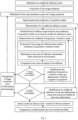
- a method of controlling tooth positioning involves the steps mentioned above.
- step a an initial reference model of the patient's arches, or part of the arches, is created (see figure 2 ).
- the initial reference model is a three-dimensional digital model of the patient's arches, for example of the .stl or .Obj, .DXF 3D, IGES, STEP, VDA, or Point Cloud type.
- 3D such a model, called "3D" can be observed from any angle.
- the initial reference model is preferably prepared at the beginning of treatment.
- the initial reference model may correspond to a position of the patient's teeth before treatment or to a position of the patient's teeth that the treatment is intended to achieve.
- the initial reference model is classically calculated from a first three-dimensional model corresponding to the positioning of the patient's teeth before treatment.
- the initial reference model is preferably prepared less than six months, preferably less than three months, and more preferably less than one month after the end of orthodontic treatment, usually immediately after the end of treatment. It thus corresponds to a substantially optimal positioning of the teeth.
- the initial reference model can also be prepared independently of any treatment, for example because the patient wants to monitor the movements of his teeth.
- the initial reference model can be prepared from measurements taken on the patient's teeth or from a physical model of their teeth, for example a plaster model.
- the initial reference model is preferably created by means of a professional device, for example by means of a 3D scanner, preferably implemented by a healthcare professional, for example by an orthodontist or an orthodontic laboratory.
- a professional device for example by means of a 3D scanner
- a healthcare professional for example by an orthodontist or an orthodontic laboratory.
- the patient or the physical model of his teeth can be advantageously arranged in a precise position and the professional device can be improved. This results in a very precise initial reference model.
- the initial reference model preferably provides information on the positioning of the teeth with an error of less than 5/10 mm, preferably less than 3/10 mm, preferably less than 1/10 mm.
- the orientation of the initial reference model in space is determined, and in particular, preferably, the occlusion plane and the median longitudinal plane.
- the occlusal plane and the median longitudinal plane can be determined manually, approximately. However, the inventors have discovered methods for determining these planes by computer processing.
- the reference model is a model of the closed-mouth arches, i.e. in a position in which teeth of the upper arch are in contact with teeth of the lower arch.
- the initial reference model provided by a three-dimensional scanner makes it possible to distinguish the upper arch from the lower arch.
- the model is provided in the form of two files corresponding to these arches respectively, and comprising data allowing the models of these arches to be positioned relative to each other in the occlusion position.
- the initial reference model can thus be oriented along the occlusion plane (Fig. 3d).
- the initial reference model does not include data to position the upper and lower arches relative to each other, it is preferable to use an occlusion bite showing the contact points between the upper and lower teeth, then reposition the models of the upper and lower arches relative to this occlusion bite.
- the median longitudinal plane is perpendicular to the occlusal plane, but its orientation is not known.
- the cycle of the previous operations is continued, preferably until all the contact points have been rotated 360° around the barycenter O.
- the correlation coefficients corresponding to the different orientations of all the contact points are then compared.
- the axis of the curve which leads to the highest correlation coefficient is then considered to be included in the median longitudinal plane, which makes it possible to define exactly the orientation of the latter.
- the orientation in space of the initial reference model is thus perfectly determined, quickly.
- a part that corresponds to a tooth is delimited by a gingival margin that can be decomposed into an inner gingival margin (on the side of the inside of the mouth relative to the tooth), an outer gingival margin (oriented towards the outside of the mouth relative to the tooth) and two lateral gingival margins.
- the gingival margins correspond to regions in which the orientation of the surface defined by the initial reference model undergoes large amplitude modifications. These orientation variations can be identified using known techniques, for example by identifying changes in the direction of the normal to the modeled surface.
- Figure 4a represents a view of the initial reference model processed to show these changes in direction.
- the Figure 4b shows the inner gingival margin which can be extracted by image analysis of the Figure 4a .
- the inner and outer gingival contours of an arch approach each other on either side of a tooth.
- the shortest path is sought, on the surface of the initial reference model, between the two points of the inner and outer gingival edges thus brought together and which are substantially opposite each other.
- the search for the shortest path between two points on a three-dimensional model uses well-known optimization techniques.
- this search results from a metaheuristic method, preferably evolutionary, preferably simulated annealing.
- the initial reference model can be stored in a centralized database, grouping the initial reference models of a plurality of patients.
- This database can be physically installed in a specialized establishment. It can also be installed in a laboratory or an orthodontic office, which limits the transfer of confidential information.
- the initial reference model is provided to the patient.
- a computer file corresponding to the initial reference model is stored on a removable medium, for example on a USB stick or on an electronic card, preferably on a mobile phone, tablet or laptop of the patient, and in particular on the personal device that will preferably be used in steps b) and following.
- the patient or a dental care professional loads the initial reference model into said individual device or makes it available for loading into said individual device.
- the patient preferably loads the initial reference model from the internet.
- the reference model is not given to the patient.
- the reference model is only made available to a specialized establishment to implement steps c) to f). It can remain stored in the establishment in which it was made in step a) and where, preferably, steps c) to f) are implemented.
- step b an updated image of a portion of an arch, an arch or arches is taken using an image acquisition device.
- Step b) is preferably performed by the patient or a relative of the patient, but may be performed by a dentist.
- the updated image is taken after a time interval ⁇ t after step a).
- the time interval ⁇ t may be predetermined. It may be constant, regardless of the occurrence of the method, i.e. whether this interval concerns the first execution of the method or a subsequent execution. It may be variable, and depend for example on the results obtained following a previous execution of the method. In particular, for the control of recurrence, the time interval ⁇ t may be all the shorter as this execution has made it possible to detect a significant drift.
- the time interval ⁇ t is determined by the orthodontist, based on a schedule of checks. Depending on the evolution of the position of the teeth, the orthodontist can modify this schedule and modify the time interval ⁇ t accordingly.
- the method for checking the positioning of teeth according to the invention is executed several times, the time intervals between each execution being able to be identical or different. The time intervals between two successive executions can all be determined before the first execution to correspond to a schedule of checks developed by the orthodontist.
- the time interval ⁇ t can also be indeterminate and depend for example on decisions of the patient.
- the creation of an updated image can be done during a dental appointment or at any time when the patient wants it, or even independently of any orthodontic treatment.
- the time interval ⁇ t is preferably determined to correspond to a potentially significant change in tooth positioning.
- the time interval ⁇ t is preferably less than three months in the first year after treatment. After this first year, the time interval ⁇ t is preferably greater than one month, or even greater than six months or greater than twelve months. In particular for the detection of tooth drift, a time interval of between six months and eighteen months is suitable.
- At least one reminder informing the patient of the need to create an updated image is sent to the patient.
- This reminder may be in paper form or, preferably, in electronic form, for example in the form of an email, an automatic alert from the mobile specialized application or an SMS.
- Such a reminder may be sent by the orthodontic practice or laboratory or by the dentist or by the patient's mobile specialized application, for example.
- an updated image is acquired before the teeth have been able to move significantly, substantially at the same time as the creation of the initial reference model, preferably less than 7 days, less than 3 days, less than 1 day after step a), i.e. before the teeth have been able to move significantly.
- the image acquisition device is a commercially available personal device, for example a mobile phone, a so-called “connected” camera, a so-called “smart watch”, or a tablet or a personal computer, fixed or portable, comprising an image acquisition system, such as a webcam or a camera, preferably a digital camera.
- an image acquisition system such as a webcam or a camera, preferably a digital camera.
- the updated image can be created by a person who does not have any specific knowledge of orthodontics, and in particular who does not have any degree in orthodontics or dentistry.
- the same acquisition device is used to take all updated images.
- the image acquisition device preferably weighs less than 3 kg, less than 2 kg, less than 1 kg, less than 500 g, preferably less than 300 g.
- Step b) can therefore advantageously be carried out at a distance from step a), i.e. in a location different from that in which step a) is carried out, in particular more than 50 m, more than 100 m, more than 1 km from the location where step a) is carried out, in particular outside an orthodontic practice.
- step b) is not carried out in a dental practice, an orthodontic practice or an orthodontic laboratory, except, possibly, during a session intended to train the patient.
- step b at least one updated image in the closed mouth position and at least one updated image in the open mouth position are taken.
- the closed mouth image advantageously makes it possible to identify the relative movements between the two arches.
- the updated open mouth image advantageously makes it possible to clearly identify the contours of the teeth, without the teeth of the upper arch masking the teeth of the lower arch or vice versa.
- Updated images can be taken for either the upper arch, the lower arch, or preferably both arches, in whole or in part.
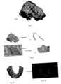
- a dental retractor is used in step b), as shown in the Figures 5a and 5c .
- the primary function of the retractor is to spread the lips apart to improve the visibility of the teeth.
- a retractor is given to the patient, for example, during an appointment with their orthodontist or dentist.
- the image acquisition device preferably provides color images, and/or infrared images of the patient's mouth, or even the patient's face.
- the color images preferably represent the patient's mouth with the actual colors of that mouth.
- the infrared images advantageously make it possible to show the teeth with excellent contrast.
- the image acquisition device comprises a specialized application for implementing step b), but also, preferably, the following steps, preferably all of the following steps. More preferably, this application manages reminders and informs the patient of the need to create an updated image.
- the specialized application is loaded into the image acquisition device from a physical medium such as a USB key or a CD-ROM, or is downloaded from the Internet or over the air.
- the specialized application is provided to the patient by the orthodontic practice and/or laboratory.
- it may take the form of an application of the type commonly downloaded on Apple ® brand iPhones or devices of all brands implementing the Android ® operating systems or any other operating system.
- the image acquisition device preferably comprises a camera or a video or infrared camera, which the user, for example the patient or one of their relatives, positions using a viewfinder or a screen, before activating it.
- a method of controlling the positioning of teeth according to the invention does not require precise positioning of the image acquisition apparatus relative to the teeth.
- no positioning constraint is imposed to ensure that the image acquisition apparatus is positioned within 30 cm, 20 cm, 10 cm or 5 cm of a given location.
- the image acquisition device includes foolproofing means facilitating its approximate positioning relative to the patient before the acquisition of the updated image.
- the user may be guided by written and/or voice messages for the acquisition.
- the personal device may announce “take a photo from the front”, emit a signal to inform the user that the photo is acceptable or that on the contrary, he must retake a photo, announce “take a photo from the right”, preferably by displaying an arrow to guide the user, etc.
- the end of the acquisition process may also be announced by the device.
- the device may also assist with positioning, for example by visual messages (for example by displaying arrows), and/or sound messages (such as a succession of beeps whose frequency increases as the positioning of the device improves), and/or written and/or voice messages (“higher”, lower”, etc.).
- the foolproofing means may in particular comprise references which appear on the viewfinder or the screen.
- the references may for example comprise a line intended to be aligned with the general direction of the joint between the upper teeth and the lower teeth when the teeth are clenched by the patient, and/or a vertical line intended to be aligned with the joint between the two upper incisors.
- the references may also refer to other parts of the patient. For example, they may be consisting of marks corresponding to the position of the eyes or taking the form of an outline in which the patient's mouth or face must be positioned.
- the reference(s) are preferably "still" on the screen, that is, they do not move on the screen when the acquisition device is in motion.
- the reference(s) each correspond to a reference mark carried by a reference device attached to the patient, i.e. which the patient did not have before the implementation of the method, preferably carried by a dental retractor.
- a reference device may also be a piece bitten by the patient.
- the registration mark may have an area greater than 0.5 mm 2 , preferably greater than 1 mm 2 , preferably greater than 2 mm 2 , preferably greater than 5 mm 2 , preferably greater than 10 mm 2 , or even greater than 20 mm 2 , or even greater than 30 mm 2 , and/or less than 50 mm 2 .
- the registration marks may be the same or different.
- the reference marks may differ in particular depending on their position, for example depending on whether they are in the upper or lower part of the reference frame, and in particular of the spacer, or to the right or left of the reference frame, and in particular of the spacer.
- the reference mark may be identical or different from the corresponding reference. It is preferably of geometric shape, for example a point, one or more lines, for example parallel, a star, a circle, an oval, a regular polygon, in particular a square, a rectangle or a diamond.
- the identification mark may also be an image, a letter, a number or a sequence of letters and/or numbers.
- the registration mark is preferably of a different color from the surrounding surface of the spacer, preferably so as to provide high contrast.
- a registration mark may be visible or invisible to the naked eye, provided that it appears on the screen of the acquisition device.
- the registration marks are preferably spaced apart from each other such that, when corresponding to their respective references on the display, at least first and second registration marks are less than 3 cm, preferably less than 2 cm, preferably less than 1 cm, preferably less than 0.5 cm, from first and second edges, respectively, of the display.
- the first and second edges are preferably opposite edges of the display.
- the identification mark may have one or more dimensions and/or a shape and/or a colour identical to or different from that(those) of the corresponding reference.
- the "correspondence" of a reference and a registration mark is a predefined arrangement of one in relation to the other. It indicates a particular positioning of the acquisition device in relation to the registration mark. The correspondence depends on the nature of the reference and the registration mark.
- the predefined situation, which corresponds to target acquisition conditions may in particular be a total or partial superposition, a juxtaposition, or an alignment of the reference and the registration mark.
- the exact superposition of the reference and the registration mark not only determines the direction in which the objective of the acquisition device should point and/or the distance between the acquisition device and the spacer, but also, if the reference and/or the registration mark are asymmetrical, the orientation of the acquisition device around this direction.
- the dimensions and/or areas of a registration mark and the corresponding reference and/or the distance between several registration marks and between corresponding references can be used to adjust the distance between the acquisition device and the arches.
- the references are defined, at least partially, from information provided by the initial reference model.
- the reference can be a view of the initial reference model, for example a front view or a right view or a left view of the initial reference model, made visible, transparently, on the screen of the image acquisition device during acquisition. It is thus very easy for the patient to approximately superimpose such a view with the teeth that he must photograph.
- a kit advantageously allows image acquisition without resorting to a specialist, in particular an orthodontist.
- Image acquisition can be carried out in particular by the patient himself or by one of his relatives, with a simple mobile phone, anywhere, and in particular outside a medical, dental or orthodontic practice.
- the image acquisition device does not need to be mechanically stabilized, for example by means of a tripod or by integration into a device placed on the ground.
- an acquisition kit does not allow very precise positioning of the acquisition device relative to the teeth.
- the accuracy of the positioning of the retractor relative to the teeth is limited.
- the person creating the images also positions the image acquisition device approximately, despite the matching of the registration mark relative to the reference on the screen.
- image processing does not, however, require great accuracy in the positioning of the acquisition device at the time the images are acquired.
- no measurements on the teeth are taken to place the acquisition device in the matching position.
- no reference mark corresponding to a reference appearing on the screen is attached directly to the teeth or to the gum or to a dental arch of the patient.
- the acquisition device may in particular be a mobile telephone and the program may be a specialized application for mobile telephone.
- the retractor may have the characteristics of retractors used hitherto. It conventionally comprises a support provided with a rim extending around an opening and arranged so that the patient's lips can rest thereon while leaving the patient's teeth visible through said opening ( Figure 5a and Figure 5c ).
- the spacer comprises at least three reference marks and the computer program makes it possible to display one or more corresponding references on the screen of the acquisition device.
- the positioning of the image acquisition device results from the sole matching of references appearing on the screen of said acquisition device with corresponding reference marks, preferably with reference marks of a dental retractor.
- the reference(s) that appear on the screen are determined based on the patient and/or the therapeutic treatment.
- the computer program is configured based on the patient so that the acquired images correspond specifically to the patient's needs.
- the acquisition device is therefore positioned in a substantially optimal position with regard to the particularities of the patient and/or the therapeutic treatment applied.
- the spacer reference marks preferably have several functions. First, they make it possible to guide the positioning of the image acquisition device at the time of image acquisition, by means of corresponding references appearing on the screen of the acquisition device. They also make it possible, in step c), to re-cut the updated images. Finally, the spacer reference marks, which appear on the images, make it possible, in step d), to roughly determine virtual acquisition conditions approximating the real acquisition conditions, which makes it possible to speed up the computer processing.
- Steps c) and following are preferably carried out either on a patient's personal device, preferably with the device used in step b), or with an application at a dental care professional, or with a dedicated third-party server.
- each updated image is analyzed so as to produce, for each updated image, an updated map relating to at least one discriminating information.
- the image analysis may include a re-cropping of the updated image in order to isolate the relevant part, in particular to remove, at least partially, from the updated image the elements which were not the subject of the initial reference model, such as the patient's nose or eyes or the retractor.
- This re-cropping, or "cropping” is facilitated by the representation of registration marks on the updated image.
- the spacer 10 carries at least three non-aligned reference marks 12. If the spacer is in several parts, for example conventionally in two parts, each part preferably carries at least three non-aligned reference marks.
- the shape of a registration mark for example an asymmetrical shape, can also be used to mark the position of the spacer on the updated image.
- the registration marks have shapes and/or colors that facilitate their identification on an updated image.
- they may be black while the remainder of the spacer is white.
- the locator marks have shapes and/or colors that allow them to be individually identified. For example, they may each be a different color.
- Identifying the registration marks on the updated image allows the identification of the area of the updated image containing the elements that were the subject of the initial reference model, i.e. the teeth and gums.
- the updated image can then be cropped accordingly. Comparing the Figures 5a and 5b, or 5c and 5d , illustrates the effect of cropping on an updated image.
- An updated map represents discriminative information in the updated image frame of reference.
- the Figure 6b is an updated tooth contour map obtained from the updated image of the Figure 6a .
- the discriminating information is preferably selected from the group consisting of contour information, color information, density information, distance information, brightness information, saturation information, reflection information and combinations of these information.
- This processing involves, for example, the application of well-known masks or filters, provided with image processing software. Such processing makes it possible, for example, to detect regions of high contrast in order to determine contours.
- the discriminant information is optimized by means of an optimization method comprising steps C1 to C3.
- step d the actual acquisition conditions during step b) are roughly determined. In other words, at least the relative position of the image acquisition device at the time it took the updated image (position of the acquisition device in space and orientation of this device) is determined. Step d) advantageously makes it possible to limit the number of tests on virtual acquisition conditions during step e), and therefore makes it possible to considerably accelerate step e).
- one or more heuristic rules are used. For example, preferably, conditions corresponding to a position of the image acquisition device behind the teeth or to a distance from the teeth greater than 1 m are excluded from the virtual acquisition conditions that may be tested in step e).
- registration marks represented on the updated image, and in particular registration marks 12 of the spacer are used to determine a substantially conical region of space delimiting virtual acquisition conditions capable of being tested in step e), or "test cone".
- At least three non-aligned reference marks 12 are preferably provided on the spacer 10, for example, and their relative positions on the spacer are precisely measured.
- the registration marks are then marked on the updated image as described above.
- Simple trigonometric calculations can be used to approximately determine the direction in which the updated image was taken.
- a cone oriented in this direction, whose apex is at the retractor and whose apex half-angle is preferably less than 10°, preferably less than 5°, for example 3° can then be defined as a "test cone".
- the apex half-angle corresponds to a degree of uncertainty. The smaller the apex half-angle, the greater the probability that the virtual acquisition conditions corresponding to the real acquisition conditions are outside the test cone.
- the acquisition device when the updated image is taken perpendicular to the plane of the three registration marks on the spacer, it can be deduced that the acquisition device was substantially in a test cone whose axis is substantially perpendicular to this plane when the updated image was taken. If the relative positions of the three registration marks on the updated image are different from those that the registration marks occupy on the spacer, the axis of the test cone in which the search for the positioning of the acquisition device is limited during the acquisition of the updated image is inclined relative to the plane of the registration marks, as shown in the figure 7 .
- the spacer comprises independent left and right parts, each of which comprises at least three registration marks, preferably at least four registration marks.
- a left test cone can thus be determined by means of the registration marks on the left part and a right test cone can be determined by means of the registration marks on the right part of the spacer.
- the virtual acquisition conditions that can be tested can then be limited to positions of the acquisition device in space belonging to these two test cones. It can also be considered that the best evaluation of the position of the acquisition device corresponds to the average position between the best position in the left test cone and the best position in the right search cone.
- the position of the registration marks on the updated image also allows the attitude of the acquisition device to be assessed when capturing the updated image. For example, if two registration marks are known to be approximately aligned in a horizontal direction when acquiring the updated image, the direction of the line containing these two points on the updated image provides an indication of the orientation of the acquisition device under actual acquisition conditions.
- the size and area of the registration marks on the updated image or their spacing can be used to assess the distance between the image acquisition device and the teeth when acquiring the updated image, and thus reduce the test cone to a truncated cone.
- step d data provided by the acquisition device and concerning its orientation, for example gyroscopic data, can also be used.
- step d) the calibration of the actual acquisition device during step b) is roughly determined.
- each calibration parameter acts on the acquired image is well known.
- the operation of an acquisition device can be conventionally modeled so as to be able to test a particular calibration on the acquired image.
- the inventors have reversed such a model, without any particular technical difficulty, so that by analyzing the representation of the spreader, it is possible to roughly evaluate the calibration of the acquisition device during step b).
- the ratio between the area of the registration marks on the updated image and the area of the updated image makes it possible to evaluate the focal length of the acquisition device during step b).
- the representation of a registration mark whose optical characteristics are known makes it possible to evaluate the exposure time and the sensitivity.
- a reference mark is a relief that does not extend exclusively in the general plane of the retractor, corresponding to a plane parallel to the frontal (or coronal).
- a reference mark is a relief that extends in a plane substantially perpendicular to the general plane of the retractor.
- the relief may in particular have the shape of a tab which, when the retractor is in its service position, extends towards the back of the mouth.
- Step d) allows only a rough assessment of the actual acquisition conditions. Step d), however, allows the determination of a restricted set of virtual acquisition conditions likely to correspond to the actual acquisition conditions, and, within this set, virtual acquisition conditions constituting the best starting point for step e1) described below.
- Step d) also makes it possible to detect updated images that are unsuitable for continuing the method, for example an updated image that would not show the registration marks.
- the method is then repeated in step c) with a new updated image.
- step d) the different methods that can be implemented in step d) can be combined.
- step e) is to modify the initial reference model until an updated reference model is obtained that corresponds to the updated image.
- the updated reference model is therefore a digital three-dimensional reference model from which the updated image could have been taken if this model had been real.
- a succession of reference models "to be tested” is therefore tested, the choice of a reference model to be tested preferably being dependent on the level of correspondence of the reference models "to be tested” previously tested with the updated image.
- This choice is preferably made by following a known optimization method, in particular chosen from metaheuristic optimization methods, preferably evolutionary, in particular in simulated annealing methods.
- step e1 it is determined that the reference model to be tested is the initial reference model during the first execution of step e2).
- step e2 we begin by determining virtual acquisition conditions to be tested, i.e. a virtual position and orientation likely to correspond to the real position and orientation of the acquisition device when capturing the updated image, but also, preferably, a virtual calibration likely to correspond to the real calibration of the acquisition device when capturing the updated image.
- the first virtual acquisition conditions to be tested may be random. Preferably, they are chosen from the limited set determined in step d), and more preferably, correspond to virtual acquisition conditions corresponding, according to step d), to the most promising virtual acquisition conditions, i.e. constituting the best springboard for approaching, as quickly as possible, the real acquisition conditions (step e21)).
- the image acquisition device is then virtually configured in the virtual acquisition conditions to be tested in order to acquire a reference image of the reference model to be tested in these virtual acquisition conditions to be tested.
- the reference image therefore corresponds to the image that the image acquisition device would have taken if it had been placed, relative to the reference model to be tested, and optionally calibrated, in the virtual acquisition conditions to be tested (step e22)).
- the updated image was taken when the position of the teeth was exactly that in the reference model to be tested, and if the virtual acquisition conditions are exactly the real acquisition conditions, the reference image is therefore exactly superimposable on the updated image.
- the differences between the updated image and the reference image result from errors in the evaluation of the virtual acquisition conditions (if they do not correspond exactly to the real acquisition conditions) and from movements of the teeth between step b) and the reference model to be tested.
- a reference map representing the discriminant information is produced from the reference image (step e23).
- the updated and reference maps both of which bear the same discriminant information, are then compared and the difference between these two maps is evaluated by means of a score.
- the discriminant information is the outline of the teeth
- the virtual acquisition conditions include the calibration parameters of the acquisition device.
- the score is higher as the values of the calibration parameters tested are close to the values of the calibration parameters of the acquisition device used in step b).
- the reference image has blurred regions and sharp regions that do not correspond to the blurred regions and sharp regions of the updated image. If the discriminating information is the outline of the teeth, the updated and reference maps will therefore not represent the same outlines and the score will be low.
- the score can be for example a correlation coefficient.
- the score is then evaluated using a first evaluation function.
- the first evaluation function is used to decide whether cycling on step e2) should be continued or stopped.
- the first evaluation function can for example be equal to 0 if cycling should be stopped or equal to 1 if cycling should continue.
- the value of the first evaluation function may depend on the score achieved. For example, it may be decided to continue cycling on step e2) if the score does not exceed a first threshold. For example, if an exact match between the updated and reference images leads to a score of 100%, the first threshold may be, for example, 95%. Of course, the higher the first threshold, the better the accuracy of the evaluation of the virtual acquisition conditions if the score manages to exceed this first threshold.
- the value of the first evaluation function may also depend on scores obtained with previously tested virtual acquisition conditions.
- the value of the first evaluation function may also depend on random parameters and/or the number of cycles of step e2) already performed.
- the first evaluation function can then lead to the decision to leave the cycling although the best score obtained has not reached said first threshold. This decision can result, for example, from a number of cycles greater than a predetermined maximum number.
- a random parameter in the first evaluation function may also allow continued testing of new virtual acquisition conditions, although the score appears satisfactory.
- the evaluation functions classically used in metaheuristic optimization methods preferably evolutionary ones, in particular in simulated annealing methods, can be used for the second evaluation function.
- step e2 If the value of the first evaluation function indicates that it is decided to continue the cycling on step e2), the tested virtual acquisition conditions are modified (step e25)) and a cycle is started again (step e2)) consisting of producing a reference image and a reference map, then comparing this reference map with the updated map to determine a score.
- the modification of the virtual acquisition conditions corresponds to a virtual displacement in space and/or to a modification of the orientation and/or, preferably, to a modification of the calibration of the acquisition device.
- This modification may be random, provided however that the new virtual acquisition conditions to be tested always belong to the set determined in step d).
- the modification is preferably guided by heuristic rules, for example by favoring the modifications which, according to an analysis of the previous scores obtained, appear the most favorable for increasing the score.
- FIGS. 12a and 12b illustrate for example the effect of a modification of the virtual acquisition conditions, in this case a modification of the focal length, on the reference image.
- the cycling on e2) is continued until the value of the first evaluation function indicates that it is decided to exit this cycling and to continue to step e3), for example if the score reaches or exceeds said first threshold.
- the optimization of the virtual acquisition conditions in step e2) is preferably performed using a metaheuristic method, preferably evolutionary, preferably a simulated annealing algorithm. Such an algorithm is well known for nonlinear optimization.
- the method can be stopped (failure situation) or resumed at step c) with new discriminating information and/or with a new updated image.
- the method can also be continued with the virtual acquisition conditions corresponding to the best score achieved.
- a warning can be issued in order to inform the user of the error on the result.
- step e2 If cycling was left at step e2) when a satisfactory score could be obtained, for example because the score reached or even exceeded said first threshold, the virtual acquisition conditions correspond substantially to the real acquisition conditions.
- the virtual acquisition conditions include the calibration parameters of the acquisition device.
- the method conducted thus makes it possible to evaluate the values of these parameters without it being necessary to know the nature of the acquisition device or its adjustment.
- Step b) can therefore be carried out without any particular precaution, for example by the patient himself using his mobile telephone.
- the search for the actual calibration is carried out by comparing an updated image with views of an initial reference model under virtual acquisition conditions that are being tested.
- the updated image does not require that the updated image show a calibration standard gauge, i.e. a gauge whose characteristics are precisely known to determine the calibration of the acquisition device.
- WO2006/065955 describes the use of images to make three-dimensional models in the field of orthodontic treatments.
- this document does not describe a method for using simple photographs, typically showing partial images of the teeth, blurred image portions and variable reflections, generally taken non-simultaneously, without the need to select remarkable points on the images, and with an acquisition device whose calibration is not known.
- the updated images are not used to create a completely new updated three-dimensional model, but only to modify the initial, very precise reference model.
- a completely new updated three-dimensional model created from simple photographs taken without special precautions would be too imprecise for a comparison with the initial reference model to lead to conclusions about tooth movement.
- Differences may remain between the determined virtual acquisition conditions and the real acquisition conditions, in particular if teeth have moved between steps a) and b).
- the correlation between the updated and reference images can then be further improved by repeating step e2), the reference model to be tested then being modified by moving one or more tooth models (step e3)).
- the search for the reference model that best approximates the positioning of the teeth during the acquisition of the updated image can be carried out as the search for the virtual acquisition conditions that best approximate the real acquisition conditions (step e2)).
- the score is evaluated by means of a second evaluation function.
- the second evaluation function makes it possible to decide whether the cycling on steps e2) and e3) should be continued or stopped.
- the second evaluation function can for example be equal to 0 if the cycling should be stopped or be equal to 1 if the cycling should continue.
- the value of the second evaluation function preferably depends on the best score obtained with the reference model to be tested, i.e. the differences between the updated and reference maps, in the virtual acquisition conditions which best approximate said real acquisition conditions.
- the value of the second evaluation function may also depend on the best score obtained with one or more previously tested reference models.
- the score may be decided to continue cycling if the score does not exceed a second minimum threshold.
- the value of the second evaluation function may also depend on random parameters and/or the number of cycles of steps e2) and e3) already performed.
- the evaluation functions classically used in metaheuristic optimization methods preferably evolutionary ones, in particular in simulated annealing methods, can be used for the second evaluation function.
- the reference model to be tested is modified and a cycle is started again (steps e2) and e3)) with the new reference model to be tested.
- the modification of the reference model to be tested corresponds to a displacement of one or more tooth models.
- This modification can be random.
- the modification is preferably guided by heuristic rules, for example by favoring the modifications which, according to an analysis of the previous scores obtained, appear the most favorable to increase the score.
- we search for the displacement of a tooth model that has the greatest impact on the score we modify the reference model to be tested by moving this tooth model, then we continue the cycling on steps e2) and e3) so as to optimize the score.
- the search for a reference model with cycling on steps e2) and e3) to find the positions of the tooth models that optimize the score is preferably performed using a metaheuristic method, preferably evolutionary, preferably a simulated annealing algorithm. Such an algorithm is well known for nonlinear optimization.
- the method can be stopped (failure situation) or resumed at step c) with new discriminating information and/or with a new updated image.
- the choice of the new discriminating information and/or the new updated image may depend on the scores obtained previously, in order to favor the discriminating information and/or the updated image which, in light of these scores, appear the most promising.
- New discriminating information obtained for example by combining other discriminating information already tested, may be used. If appropriate, it may also be requested to acquire one or more new updated images. Preferably, indications are provided to guide the positioning of the acquisition device for the capture of this new updated image. For example, the patient may be instructed that he should take a photo of the right part of his lower arch.
- the process can also be continued with the reference model and the virtual acquisition conditions corresponding to the best score achieved.
- a warning can be issued to inform the user of the error in the result.
- the virtual acquisition conditions correspond substantially to the real acquisition conditions and the tooth models in the reference model obtained (called the “updated reference model”) are substantially in the position of the patient's teeth at the time of step b).
- step f) the updated reference model, resulting from the optimization by displacement of the tooth models, is compared with the initial reference model.
- the updated reference model corresponds substantially to the updated image.
- the comparison in step f) therefore makes it possible to observe the differences between the positioning of the teeth in step a) (initial reference model) and during the acquisition of the updated image (step b)).
- the method thus makes it possible to determine precisely, for each of the teeth, the movements between these two steps.
- a method for controlling the positioning of teeth according to the invention can for example be used to remotely monitor the evolution of an orthodontic treatment, and thus optimize the appointments of patients with their orthodontists.
- control method according to the invention is implemented several times for the same patient, preferably successively with several discriminating information items, preferably more than 2, more than 3, more than 5 discriminating information items for each updated image and/or with several updated images, preferably more than 2, more than 3, more than 5 updated images.
- the evaluation of the movement of a tooth can thus be refined by taking into account the different scores obtained. The comparison of these scores also makes it possible, where appropriate, to discard the discriminating information items and/or the unsatisfactory updated images.
- the information may be to schedule a visit to the dentist or orthodontist.
- the practical information depends on the degree of displacement of the teeth.
- an appointment may be automatically made with the dentist or orthodontist, depending on the amplitude and/or nature of the detected displacements.
- the practical information is used to modify the time interval after which the patient should be notified that a new updated image should be created.
- the individual apparatus is capable of displaying images, or even a sequence of images, showing the positioning of the teeth at different dates. These images may be presented in the form of an animation, for example in the form of a slide show or a movie.
- the image acquisition device is a telephone which makes it possible to transmit the results obtained by implementing the method, preferably in a secure manner.
- the communication may for example be carried out, at least in part, by radio waves, preferably following at least one protocol chosen from the edge, 3G, 4G, udmsa, hpdmsa, bluetooth, and wifi protocols, or by any other protocol, adapted to the mobile or nomadic equipment, by wired synchronization with the personal computer, or by optical transmission.
- radio waves preferably following at least one protocol chosen from the edge, 3G, 4G, udmsa, hpdmsa, bluetooth, and wifi protocols, or by any other protocol, adapted to the mobile or nomadic equipment, by wired synchronization with the personal computer, or by optical transmission.
- a method for checking the positioning of teeth allows precise and efficient checking of the positioning of the patient's teeth, substantially without any strain on the patient.
- simple photographs taken without any special precautions, for example with a mobile phone, are sufficient. The patient can therefore easily implement this method.
- the orthodontic appliance worn by the patient may be the first orthodontic appliance initially made available to him for his orthodontic treatment or a replacement appliance made available to him at a later date.
- the first orthodontic appliance can be manufactured using a conventional process.
- the orthodontist may, at the start of the treatment, determine a first series of splints adapted so that the teeth reach a position corresponding to an objective reference model, preferably representing a final set-up, manufactured following a step b'), as described below. This determination may be carried out in a conventional manner.
- the first splint of this first series is made and provided to the patient.
- replacement orthodontic appliance refers to the appliance resulting from this adaptation of the treatment.
- the replacement orthodontic appliance can therefore be the orthodontic appliance that was worn until then, referred to as “worn orthodontic appliance”, and adapted, for example by changing the orthodontic arch fixed to the teeth or modifying its tension.
- the replacement orthodontic appliance can also be a new orthodontic appliance, in particular when active aligners are used for the treatment.
- a method of adapting an orthodontic appliance according to the invention comprises steps a') to f') described above, and illustrated in the figure 14 .
- Step a') is identical to step a) and may comprise one or more of the optional features of step a) described in the present description. It leads to an initial reference model which digitally represents, in three dimensions, at least the part of the arches which comprises the teeth of the patient to be treated.
- the manufacture of the initial reference model can be carried out by any known conventional methods.
- Step a') is preferably the first step.
- the objective reference model is conventionally determined from the initial reference model.
- Step b' consists of manufacturing an objective reference model which digitally represents, in three dimensions, the teeth to be treated in a position to be reached at a time during the treatment, in particular at the end of the treatment ("final set-up") or at a predetermined intermediate stage of the treatment (“intermediate set-up”), for example at a time planned for changing the splint or modifying the tension of the orthodontic arch.
- intermediate set-ups can be performed at the beginning of treatment.
- the number of intermediate set-ups can be greater than 1, 2, 10, 20, 30, 40, 50 or 60.
- the duration between two successive intermediate set-ups can be less than 10 weeks, 8 weeks, 6 weeks, 4 weeks, 2 weeks, or 1 week.
- the fabrication of the objective reference model can be carried out by all known conventional methods.
- the objective reference model results from a deformation of the initial reference model.
- the tooth models which correspond to the teeth to be treated are conventionally virtually moved to their desired position.
- Step b') is preferably carried out substantially at the same time as step a'). However, it can be carried out at any time up to the first use of the objective reference model.
- step a' the time when the orthodontist decides that the patient needs to have a check of the effectiveness of his treatment, for example more than 1 week or more than 2 weeks after step a') of making the initial reference model. It can also be decided by the patient or planned.
- the updated reference model is obtained by deforming the initial reference model, preferably by moving the tooth models, using information from the updated images. More precisely, the deformation is optimized, preferably by an evolutionary method, preferably by simulated annealing, so that the updated images correspond as best as possible ("best fit") to views of the deformed initial reference model, then called "updated reference model". In other words, these views are substantially identical to the updated images.
- the updated reference model is made accessible to the orthodontist in real time.
- a patient device for example with his telephone
- it can be sent to the orthodontist.
- the orthodontist is thus notified and can intervene accordingly.
- the updated reference model thus provides positioning parameter values at the time of acquisition of updated images for tooth points.
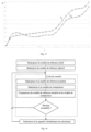
- the value of a positioning parameter for a point of a tooth is represented on a graph.
- the graph represents, for each control cycle, the value of this positioning parameter, for this point of the tooth.
- a curve connects these points.
- the time scale preferably on the abscissa, is linear. The dynamics of the treatment, as regards this parameter, is advantageously immediately perceptible. The orthodontist and/or the patient can thus immediately perceive a loss of effectiveness of the orthodontic appliance and act accordingly.
- Step d') of determining a comparison model can be performed at any time before step e').
- the comparison model provides theoretical positions of the teeth, or of tooth points, at intermediate times between the start and the end of the treatment.
- the comparison model is a three-dimensional digital model. It advantageously allows a visual comparison with the updated reference model.
- the theoretical position of a tooth or of a point of a tooth results from a processing of the initial reference model and of the objective reference model, in particular from an interpolation, preferably non-linear, between the positions of this tooth or of this point between these two models.
- the position (x,y,z) of a point M of a tooth can be defined in a three-dimensional frame, for example orthonormal.
- the position of this point in the initial reference model, at time t 0 , and in the objective reference model, at time t G can be denoted (x 0 ,y 0 ,z 0 ) and (x G ,y G ,z G ), respectively.
- the comparison model depends on one or more previous updated reference models and/or one or more previous comparison models (established during previous control cycles, i.e. in particular previous steps c'). The accuracy is considerably improved.
- the determination of the comparison model depends on the evolutions between several updated reference models, preferably successive.
- updated reference models may have been made three months, two months and one month ago, at t -3 , t -2 and t -1 , respectively.
- the displacement of the barycenter of a tooth along the Ox axis between t -3 and t -2 may be for example 100 ⁇ m and the displacement between t -2 and t -1 may be 80 ⁇ m. It can then be considered, by simple linear extrapolation, that the displacement, along the Ox axis, between t -1 and today (t 0 ), will be 60 ⁇ m, which makes it possible to create a comparison model at t 0 with great precision.
- a prediction method being a process for establishing, from a predictive model, a prediction based on known data.
- a predictive model is therefore a model that allows the simulation of future tooth movement based on past data, and in particular past movements of said teeth and/or past or calculated behavior of the orthodontic appliance.
- the predictive model takes into account the action of the orthodontic appliance on the teeth.
- the displacement, along the Ox axis, between t -1 and today (t 0 ) can be estimated at 50 ⁇ m and not at 60 ⁇ m.
- a model of the orthodontic appliance is also used to simulate its action, over time, on the teeth, as a function of their positions, and in particular their position in the initial reference model and/or their position in the updated reference model.
- a method for evaluating the behavior of an orthodontic appliance makes it possible to design and/or refine such predictive models.
- a dynamic model is constructed, capable of providing the theoretical position of the teeth or of a set of tooth points, preferably of each tooth model, at any time between the start and the end of the treatment or, more generally, between the times corresponding to the initial and objective reference models.
- Software may be used for this purpose.
- Step d) may be carried out immediately after steps a') and b') have been carried out, for example less than 3 months, less than 1 month or less than 1 week after steps a') and b') have been carried out.
- the comparison model is determined to correspond to a simulation of the position of the treated teeth at a time t c as close as possible to the time of execution of step c'), and in particular to the time t a at which the updated images were acquired.
- these two times are separated by less than 1 month, less than two weeks, preferably less than a week, preferably less than a day.
- the two instants t c and t a are the same, which is particularly possible when we have a dynamic three-dimensional model, capable of providing the position theoretical teeth, at any time between the start and the end of treatment. Knowing the time t a , it is sufficient to choose, as a comparison model, the dynamic model at the time t a .
- the comparison model is always the objective reference model.
- the accuracy of the adaptation of the orthodontic appliance is however not optimal.
- step e' the updated reference model, which corresponds to the situation observed at the time of the inspection, is compared with the theoretical comparison model.
- the comparison can be made by the patient and/or the orthodontist.
- the comparison preferably comprises a determination, for each point of a set of points of the teeth of the updated reference model, preferably for at least three non-coplanar points of each tooth of the updated reference model, of the displacement (vector) between the representations of this point on the comparison and updated models.
- This displacement is preferably quantified by means of distances and/or angles in a three-dimensional reference frame Oxyz, for example in an orthonormal reference frame.
- the displacement can for example be determined in Cartesian or cylindrical coordinates.
- the analysis of the displacement of a few points of the teeth can be difficult to present or analyze.
- the points of the same tooth are considered to be rigidly linked to each other.
- the analysis of the displacement of the points of the same tooth is generalized to evaluate the displacement of all the points of this tooth, that is, the displacement of the corresponding tooth model.
- knowledge of the displacement of three non-coplanar points of a tooth makes it possible to evaluate the movement of this tooth between its representation (i.e. the corresponding tooth model) in the updated reference model and its representation in the comparison model, or "momentum".
- the quantity of movement can be expressed by differences in values of a set of positioning parameters making it possible to fix the position and orientation of an object in space, for example Cartesian coordinates of a point of the tooth, for example its barycenter, and values of angles around a fixed reference, for example orthonormal (differences between the values in the updated reference model and in the comparison model).
- the path to be traveled, from the updated reference model, to reach the comparison model is determined, for example the distance to be traveled by the barycenter of the tooth along each of the axes of a fixed orthonormal reference frame and the rotation to be performed around each of these axes.
- the speed of the movements of the points considered is evaluated, preferably using the initial reference model, and preferably one or more updated reference models determined previously, in particular during previous control cycles.
- the speed of movement of a point of a tooth, in a direction, between two successive updated reference models can be simply evaluated by dividing the distance between the representations of this point on these two models, in this direction, by the time elapsed between the production of these two models.
- the slowing down or acceleration of the movement of the points of the teeth is evaluated by comparing the speeds of two successive periods.
- the comparison allows to evaluate the quantities of movement still necessary to complete the treatment or reach the end of the intermediate treatment stage, respectively.
- the comparison also allows to evaluate the speed of tooth movements until the end of the intermediate stage or the end of treatment, respectively.
- the comparison model is a model which corresponds to an estimate of the position of the teeth expected substantially at time t a of step c'), for example determined at the start of treatment or following the immediately preceding control cycle.
- the comparison result is considered unsatisfactory if a deviation between the updated reference model and the comparison model exceeds a threshold value. For example, if the comparison model corresponds to a tooth positioning planned at the time of creation of the updated reference model, a deviation of more than 50 ⁇ m from the position of the barycenter along the Ox axis can be considered unsatisfactory. If the comparison model is the objective reference model, the threshold value to be exceeded for a deviation to produce an unsatisfactory result naturally depends on the expected residual time to reach the positioning corresponding to the objective reference model.
- the comparison preferably results in a quantification of the differences, preferably carried out and presented by a computer.
- the computer preferably presents the results of the comparison by highlighting the most significant differences.
- the comparison can also be visual.
- an orthodontist views and compares the updated reference model and the comparison model.
- a computer screen presents an image highlighting the discrepancies.
- the decision whether a gap is unsatisfactory or not may depend on a decision by the orthodontist and/or a result of a computer calculation.
- the comparison carried out in step e') leads to recommendations which are presented to the orthodontist.
- the method makes it possible to finely determine the behavior of the orthodontic appliance, and therefore to determine the factor(s) which should be modified to optimize its effectiveness.
- step e') leads to the generation of a report specifying how to modify the tension of the arch of the orthodontic appliance installed or how to manufacture a new splint.
- step e') leads to the generation of an "updated" score that can be compared to a reference score for equivalent treatments.
- these scores are presented to the patient.
- the success of the treatment is thus presented as a fun objective, the scores motivating the patient, and in particular children, to follow the treatment as best as possible in order to increase their updated score.
- step e') leads to the generation of information presenting the situation and the different options available to the patient.
- the patient can thus, for example, decide to extend his treatment or choose a new objective reference model.
- the results of the comparison are transmitted, preferably in real time, to the patient, preferably on his mobile phone.
- the patient can thus become aware of the consequences of poor compliance with the treatment.
- step f' if the result is unsatisfactory, a replacement orthodontic appliance is manufactured, by modifying the orthodontic appliance worn until then or by manufacturing a new orthodontic appliance.
- Step f') is a step typically performed during a check-up with an orthodontist.
- the manufacture of a replacement orthodontic appliance is however only carried out if the control, preferably carried out remotely, indicates that it is necessary.
- the fabrication of the replacement appliance is performed remotely, such that when the patient presents to the orthodontist, the replacement orthodontic appliance can be immediately fitted.
- an orthodontic archwire or splint can be prepared based on the assessment performed in step e').
- the orthodontic archwire or splint can be fabricated in a laboratory remote from the orthodontist's office and then mailed to the orthodontist.
- the splint can be sent directly to the patient, without intervention by the orthodontist.
- step f' the treatment schedule is modified according to the modification made to the orthodontic appliance.
- a plurality of replacement orthodontic appliances that can immediately replace the worn appliance are determined, preferably based on the patient's desired treatment speed, with increased speed potentially corresponding to additional pain.
- the patient is given a choice of treatment speed and the replacement orthodontic appliance to be manufactured is determined accordingly.
- a series of replacement orthodontic appliances can be manufactured, and preferably sent to the orthodontist or patient.
- the method comprises several control cycles comprising steps c'), d'), e') and f'), each preferably carried out at a time, for example determined at the start of treatment and/or at the request of the orthodontist and/or at the initiative of the patient.
- Two consecutive control cycles are preferably separated by a duration of less than 10 weeks, preferably less than 8 weeks, preferably less than 6 weeks, preferably less than 4 weeks, preferably less than 3 weeks, preferably less than 2 weeks.
- the number of control cycles during processing is greater than 1, greater than 3, greater than 5, greater than 10, greater than 15, or even greater than 20.
- a reminder is sent to the patient, for example by SMS, to perform a control cycle.
- the comparison model of a step d') of a control cycle is determined from the updated reference model produced during step c') of a previous control cycle, in particular of the immediately preceding control cycle, or from several updated reference models produced during steps c') of previous control cycles, for example by extrapolation.
- FIG 13 illustrates a process that includes several control cycles. It represents the curves of the theoretical (C T ) and real (C R ) time evolutions of a parameter of quantity of movement of a tooth, and more precisely, the time evolution of the position of a point M of a tooth, for example of the barycenter of this tooth, according to the Ox axis), as a percentage compared to the desired value at the end of treatment.
- a control cycle was carried out every week.
- the first control cycles allowed us to notice a drift very quickly.
- the orthodontic appliance had a tendency to move the M point too quickly. This information was presented to the orthodontist, with recommendations on how to modify the orthodontic appliance, for example to specify that it was appropriate to reduce the tension exerted by the orthodontic arch between two specific teeth.
- the patient receives, for example on his telephone, information allowing him to compare the updated reference model and the objective reference model, for example graphical representations of these two models. If the objective reference model represents the teeth at the end of the treatment ("final set-up"), he can thus decide for himself when the treatment will end.
- the theoretical time course curve can be determined in its entirety from the start of treatment, taking into account the changes to the orthodontic appliance expected during treatment.
- This curve can also be recalculated based on changes made to the orthodontic appliance that were not initially planned. For example, if the change to the orthodontic appliance made in week 3 was not initially planned, the predictive model used to establish the comparison model used after week 3, and therefore the theoretical time course curve, were preferably modified to take this unforeseen change into account. The predictive model was thus advantageously taken into account a much slower evolution of the displacement of point M along the Ox axis) than that which had been initially anticipated.
- the adaptation process allows in particular a diagnosis of the situation, or even the manufacture of a replacement orthodontic appliance, without the patient having to go to an orthodontist.
- control cycles advantageously allows the acquisition of numerous data allowing the establishment of correlations between parameters of the orthodontic appliance, its behavior and configurations of the teeth.
- the values of the parameters of the orthodontic appliance initially used, but also, at each control cycle, the parameters of the replacement orthodontic appliance are recorded in a computer.
- the parameters of the orthodontic appliance include intrinsic parameters, such as the material or shape of a splint, or the material and diameter of an orthodontic arch. They also include extrinsic parameters, resulting from its use, such as the attachment points of the orthodontic arch on the teeth or the tension of the orthodontic arch.
- An analysis module allows to compare all the collected data, according to conventional statistical analysis methods. This results in a better knowledge of the behavior of the orthodontic appliance, according to the values of its parameters and the configurations of the corresponding teeth.
- the data collected comes from several treatments, preferably more than 10, more than 100, more than 1,000, more than 10,000, more than 100,000 treatments.
- the data thus allow us to observe that, in similar configurations of teeth, a type of orthodontic appliance or a parameter of an orthodontic appliance is particularly effective in ensuring movement in a particular direction.
- This optimization can advantageously lead the orthodontist or the designer of orthodontic appliances to take into account a parameter of the orthodontic appliance classically considered negligible.
- step a A method for checking the shape of a patient's teeth is described. In step a), however, the definition of tooth models is not essential for this check.
- an updated reference model corresponding to the shape of the teeth during the acquisition of the updated image is searched for for each updated image, the search preferably being carried out using a metaheuristic method, preferably evolutionary, preferably by simulated annealing, in particular using one of the metaheuristic methods described above.
- this search involves two nested optimization loops.
- virtual acquisition conditions are first optimized in a reference model to be tested, which is initially the initial reference model, which correspond as closely as possible to the real acquisition conditions.
- the virtual position of the acquisition device relative to the reference model to be tested is sought, which offers the view of this reference model to be tested, i.e. the reference image, which is closest to the updated image.
- a virtual calibration is also sought that is likely to match the actual calibration of the acquisition device when capturing the updated image.
- the modification of the reference model results from a displacement of one or more tooth models. No deformation of the tooth models or the initial reference model is necessary.
- the modification of the reference model results from a modification of the shape of the reference model to be tested, in particular of one or more tooth models. No movement of the tooth models is necessary.
- a third optimization operation may also be implemented relating to the shape of the tooth models or the reference model to be tested and surrounding the first two optimization operations, the second optimization operation relating to the movement of the tooth models.
- an updated reference model "to be tested” is first searched for, taking into account, at best, the movement of the tooth models, the updated reference model to be tested corresponding to the updated reference model of a step e) of a method for checking the positioning of the teeth described above, then a search is made to see whether a deformation of the updated reference model to be tested can lead to a better match with the updated image.
- the updated reference model to be tested is deformed, the first two optimization operations are restarted, then, depending on the match obtained, the search is stopped or continued by performing a new deformation of the updated reference model to be tested and by restarting an execution of the first two optimization operations.
- this method makes it possible to assess whether the appearance, in particular the colour of one or more of the teeth has been modified, even when the conditions for acquiring the photographs of a patient's teeth are not predefined, for example because the photographs were taken in a bright environment or in any position of the acquisition device, in particular by the patient.
- Steps A. and B. can be performed like step b) described above.
- Steps A. and B. are preferably performed by the patient or a relative of the patient, but can be performed by a dentist.
- the time interval between these steps may be that described above between steps a) and b), for example greater than 1 week, 2 weeks, 1 month or 3 months.
- the first acquisition device may be identical to or different from the second acquisition device. It may be an acquisition device chosen from those that can be used for step b), in particular a camera or a mobile telephone.
- the acquisitions in steps A. and/or B. are carried out using a flash.
- the results are improved.
- the initial and/or updated image is overexposed.
- the reference gauges used for each of steps A. and B. have the same appearance. Preferably, during each step, they are placed in the same position relative to the patient's teeth.
- dental retractors are used for each of the steps A. and B.. These retractors may be identical or different.
- the reference gauge is carried by a retractor for at least one of the steps A. and B., preferably for each of the steps A. and B..
- the reference gauges are arranged on the retractors in the same position relative to the opening 14 of the retractor which reveals the patient's teeth ( Figure 5a ).
- the reference gauge is arranged on the retractor so as to be in proximity to the teeth whose appearance property is to be controlled.
- the reference gauge is arranged less than 3 cm, preferably less than 2 cm, preferably less than 1 cm from the part of the retractor intended to be introduced into the patient's mouth.
- each spacer comprises several reference gauges, identical or different.
- several different reference gauges of the same spacer have different aspects. The conclusions drawn from the comparison of the standardized images can be advantageously richer.
- a reference gauge may be, for example, a point identifiable on the spreader and whose appearance is known, for example whose color parameters L*, and/or a* and/or b*, measured according to standard NF ISO 7724, are known.
- the reference gauge may in particular be a reference mark of a spreader as described above.
- the acquisition conditions are substantially the same in steps A. and B.
- the two images are taken substantially from the front.
- the image acquisition device used for at least one, preferably for each of steps A. and B. comprises foolproofing means facilitating its positioning relative to the patient before image acquisition.
- the foolproofing means preferably interact with registration marks arranged on the spacer.
- the acquisition device is programmed so as to, in real time real, locate the registration marks on the retractor, analyze their relative positions or dimensions and, accordingly, inform the user of the acquisition device so that he can modify the position of the acquisition device accordingly in relation to the patient's teeth.
- foolproofing means may have one or more of the characteristics of the foolproofing means described above for step b).
- an acquisition kit is used and, preferably, an acquisition method comprising steps (a) to (e).
- the target acquisition conditions are the same in the memory of the first and second acquisition devices so that the acquisition device guides its user so that the initial and updated images are taken under substantially identical acquisition conditions.
- the target acquisition conditions are determined according to the teeth whose appearance property is to be controlled.
- the target acquisition conditions preferably correspond to an image capture facing the patient for a control relating to an incisor and they preferably correspond to a lateral image capture for a control relating to a molar.
- Step C. consists of normalizing, i.e. “correcting” the initial image and/or the updated image so that, after correction, the representations of the reference gauge on these images have the same appearance. Since the reference gauge has not changed in appearance between steps A. and B., any differences in appearance presented by the representations of the teeth on the normalized initial and updated images therefore correspond to real differences in appearance on said teeth.
- the reference gauge is searched on the initial image and on the updated image.
- a simple image analysis is sufficient for this purpose.
- Normalization may be performed on the initial image only to modify the representation of the reference gauge so that its appearance is identical to that of the representation of said reference gauge on the updated image. Normalization may alternatively be performed on the updated image only to modify the representation of the reference gauge so that its appearance is identical to that of the representation of said reference gauge on the initial image. Finally, normalization can be performed on the updated image and on the initial image in order to modify the representations of the reference gauges so that their appearances are identical to that of a standard gauge.
- Image normalization is a well-known technique in image processing.
- White balance is an example of image normalization.
- step C. Before or after step C., it is appropriate to identify, on each of the initial and updated images, a region of the teeth whose appearance evolution we wish to evaluate.
- the initial and updated images are analyzed in order to represent discriminative information, of the type described above, for example the outline of the teeth.
- the analysis of the initial and updated images may include one or more characteristics of step c), in particular relating to the nature of the discriminating information and to the processing for determining the discriminating information.
- the discriminating information is preferably optimized by means of an optimization method comprising steps C1 to C3.
- the discriminant information common to both the initial and updated images can then serve as a reference to locate said region on these two images.
- the outline of the gums can present a succession of “points” between the teeth. This outline depends on the teeth considered and can therefore serve as a reference.
- the initial and updated images are referenced relative to a reference model, preferably produced in accordance with step a) (initial reference model) or resulting from the implementation of a method for controlling the shape and/or positioning of the teeth according to the invention (updated reference model).
- This registration can be performed as described above for registering the updated image in the context of tooth shape and/or positioning control processes. Unlike these processes, however, modification of the initial reference model to arrive at the updated reference model is optional.
- This search is preferably carried out using a metaheuristic method, such as those described above.
- a method of evaluating the real acquisition conditions is preferably used, described below. This method is preferably implemented for each of the initial and updated images using the reference model. It makes it possible to "project" these images onto the reference model and therefore to locate a point of these images on the reference model.
- a region of the teeth whose appearance evolution we wish to evaluate can thus be identified with great precision on each of the initial and updated images.
- a method of monitoring the appearance of teeth may be used to check the effects on the appearance of teeth of chewing gum or drinking coffee or tea, or smoking or taking drugs, or brushing teeth.
- the patient only needs to take photographs regularly with his mobile phone to create updated images.
- the patient can then compare the appearances of the teeth on these photographs.
- the application normalizes the photographs to make them comparable, then provides a dynamic visualization of the corrected photographs, for example in the form of a slideshow or a film.
- the actual acquisition conditions to be evaluated include one or more of the following calibration parameters: aperture, exposure time, exposure time, focal length, and sensitivity.
- the modification made to the virtual acquisition conditions to be tested in step 06) is preferably carried out by means of a metaheuristic method, preferably evolutionary, preferably by simulated annealing, preferably by means of one of the metaheuristic methods cited above.
- An evaluation method is preferably used whenever it is necessary to evaluate the actual acquisition conditions of an image.
- This image which may in particular be an updated image acquired during a step b) or B. or an initial image acquired during a step A., is called an “acquired image”.
- the production of the reference model in step 001) may include one or more of the characteristics, even optional, of step a).
- the acquisition of the acquired image may include one or more of the characteristics, even optional, of step b). Preferably, it implements an acquisition kit, and preferably a method.
- Step 01) of determining the coarse virtual acquisition conditions may include one or more of the characteristics, even optional, of step c).
- Steps 02) to 06) may include one or more of the features, even optional ones, of steps e21) to e25), respectively.
- a method of optimizing or "selecting" discriminant information is intended to improve the reliability of initial discriminant information extracted from a two-dimensional image of a patient's dental arches, or "acquired image", in particular from a initial image from step A. or an updated image from step B. or b), acquired under real acquisition conditions.
- "Optimization" of the discriminant information is therefore a selection of discriminant information, following an iterative approach, so as to select from the image the most relevant discriminant information to best control the positioning and/or shape of the patient's teeth.
- the discriminating information may be, in particular, any of the discriminating information described above.
- the discriminating information may be contour information.
- the initial discriminant information classically results from the analysis of the acquired image, as described for step c).
- Methods that use such initial discriminant information implement optimizations that provide better results if the discriminant information is both abundant and of good quality.
- One objective of the optimization method is therefore to improve the quality of the initial discriminant information.
- step C1. the quality of the initial discriminant information is evaluated.
- the contrast analysis provides, for example, more or less accurate information. reliable: an area of high contrast can be assimilated to an area corresponding to an outline with a high probability and the quality of the points in this area will therefore be high.
- an area of low contrast for example a blurred area, can be assimilated to an area corresponding to an outline with a low probability and the quality of the points in this area will therefore be low.
- the probability for a point in the acquired image to belong to the outline can be chosen as an indicator of the "quality" of the discriminating information.
- a quality threshold is used to filter the initial discriminant information. If the quality threshold is high, the discriminant information retained following filtering will be small, but very reliable. If the quality threshold is low, the discriminant information retained will be abundant, but unreliable. In the example of contour information, the image analysis will then lead to retaining "false" contour points, that is, points which, due to the analysis, will be mistakenly considered as belonging to the contour of the teeth and gums.
- the quality threshold is high in order to retain only very reliable discriminatory information to be tested.
- step C2. we test the concordance, that is to say we determine a degree of concordance, between the discriminant information to be tested and the reference model.
- an “acquired” map of the discriminant information to be tested resulting from the processing of the acquired image is produced.
- step 04 the processing of the reference image makes it possible to produce a reference map representing said discriminating information.
- the selection criteria for the discriminating information represented on the reference map may be identical to or different from those used to select the discriminating information to be tested.
- the discriminant information represented on the reference map is selected with the same criteria as the discriminant information to be tested.
- the processing of the reference image can consist of retaining the points of the reference image corresponding to a contour with a high probability.
- the probability for a point of the reference image to belong to the contour can be determined as for the processing of the acquired image and also serve as an indicator of the quality of the discriminating information.
- the quality threshold can also be identical to that used for the processing of the acquired image.
- the contour represented on the reference map is then similar to that represented on the acquired map, and in particular has a substantially identical length.
- Steps 01) to 06) make it possible to determine, with the reference model, virtual acquisition conditions approximating the real acquisition conditions of the acquired image. Observing the reference model under these virtual acquisition conditions therefore provides a view that best matches the acquired image.
- the search for virtual acquisition conditions is based on the discriminant information to be tested. The degree of correspondence therefore depends on the discriminant information to be tested. The higher the quality and quantity of the discriminant information to be tested, the better the degree of correspondence between the view of the reference model under the virtual acquisition conditions and the acquired image, and the higher the degree of agreement between the discriminant information to be tested and the reference model.
- the degree of concordance may be the ratio of the number of points which belong to both the outline of the reference map and the outline of the acquired map, to the total number of points of the outline of the acquired map, or the product of the inverse of the average distance between the outlines represented on said acquired and reference maps, and the length of the outline represented on the acquired map.
- the "best” approximation of the real acquisition conditions from a discriminating information to be tested can be evaluated by a result or "score", for example by the degree of concordance.
- the cycle of steps C2. and C3. aims to optimize this result by acting on the discriminating information to be tested.
- This optimization is similar to that implemented for the methods of controlling the positioning and/or the shape of the teeth. These methods, however, act on the initial reference model, by moving the tooth models and/or by deformation of the reference model, whereas the method of optimizing the discriminant information acts on the discriminant information used to establish the acquired map.
- step C3. The operation performed in step C3. is determined by an evaluation function of the test result of step C2..
- the evaluation function takes into consideration results obtained during previous cycles C2.-C3.
- the method may be stopped if the evaluation function indicates that continuing cycles C2.-C3. does not improve the result, for example because one or more cycles C2.-C3. did not improve it or did not improve it significantly.
- the discriminant information tested during cycle C2.-C3. that led to the best result is then considered optimal.
- a new cycle C2.-C3. can be launched, after modification of the discriminant information to be tested.
- the modification to be made to the discriminant information that has just been tested can consist of an addition or a deletion of discriminant information.
- An addition of discriminant information can for example be decided if the last result is the best obtained so far and if, according to the evaluation function, the result can be further improved.
- the added discriminating information is that which, among the discriminating information not retained in step C1. and which has not yet been tested, presents the best quality.
- the addition of discriminant information may consist of adding points of the image not initially retained, never added before and whose quality, as evaluated in step C1., is the highest, that is to say whose addition is most likely to improve the result of the test of step C2.
- a suppression of discriminating information can for example be decided if the last result is worse than the previous one.
- the discriminating information added during the previous cycle can be suppressed and an addition of another discriminating information can be carried out, as described previously.
- the determination of the discriminating information to be added and/or deleted may be random. However, preferably, it results from the implementation of a metaheuristic method, preferably evolutionary, preferably by simulated annealing, preferably of the type described above.
- the figure 11 represents, superimposed on the acquired image, a reference map relating to reflection information (discriminative information).
- the acquired image is a photograph taken in a particular position and orientation of the camera. This position and orientation constitute the actual acquisition conditions of the acquired image.
- the person skilled in the art knows that, on the acquired image, the higher the brightness of a point, the higher the probability that this point belongs to a reflection zone.
- the brightness can therefore serve as an indicator of the “quality” of the reflection information.
- Filtering in step C1 may consist of retaining only the areas of the acquired image which have a brightness greater than a quality threshold, for example 70%.
- the acquired map represents these areas, which constitute the discriminatory information to be tested.
- step C2. we preferably proceed according to steps 01) to 06) to test whether the selected areas agree with the observation of the reference model.
- step 01 the acquired image is analyzed to roughly evaluate the real acquisition conditions by virtual acquisition conditions. This evaluation results from preference for an analysis of the position and/or shape of the representation, on the acquired image, of registration marks of a retractor used during acquisition.
- the roughly evaluated virtual acquisition conditions can constitute the “virtual acquisition conditions to be tested” in step 02).
- step 03 by observing the reference model from virtual acquisition conditions to be tested, a reference image is obtained.
- vectors black lines 20
- the circles 22 represent these vectors when they are observed according to their length.
- the reference map is thus constituted by these black lines 20 and circles 22.
- the circles 22 normally correspond to areas of the image corresponding to reflections.
- the discriminating information namely the reflection information
- the black lines 20 and by the circles 22 the inverse of the length of the black lines being able to serve as an indicator of the “quality” of the reflection information on the reference map, a circle corresponding to a zero length, and therefore to a maximum quality.
- the decision may be to continue the research by modifying the virtual acquisition conditions to be tested until a maximum is reached for the acquisition function.
- step 06 if this maximum is considered to have been reached, we exit the loop of steps 03) to 06). Otherwise, we determine, preferably by means of a metaheuristic method, preferably evolutionary, a modification to be made to the virtual acquisition conditions to be tested and we resume step 03).
- the ratio R is therefore maximum, for this acquired image, for example 95%.
- This ratio R then represents the result of the concordance test carried out in step C2.
- step C3 this result is evaluated using an evaluation function.
- This evaluation function preferably determines whether the result is optimal or not. If the result is considered optimal, for example because no better result can be obtained after several cycles of steps C2. - C3., the areas of the corresponding acquired map are considered to constitute optimal discriminating information.
- the acquired map is modified, for example by adding points from the acquired image, for example by adding points that have a brightness greater than 71%.
- This addition leads to the addition of circles in the areas of the acquired map, which improves the R ratio, but also to the addition of black lines, which degrades the R ratio.
- This deletion leads to the deletion of circles in the areas of the acquired map, which degrades the R ratio, but also to the deletion of black lines, which improves the R ratio.
- the modification to be made is preferably guided by a metaheuristic method, preferably evolutionary.
- steps C2. and C3. can be continued until an optimal result is determined.
- the discriminant information to be tested is then considered optimal.
- a method of optimizing discriminant information allows the construction of good quality and abundant discriminant information.
- it allows, from an initial partial contour, but of good quality, to progressively construct a more complete contour but still of good quality.
- the method for controlling the positioning and/or shape of the teeth can be implemented successively for each of the two arches or simultaneously for both arches. Furthermore, for these methods, several different devices can be implemented.
- the acquisition can be done with a mobile phone and the following steps with a desktop computer.
- the patient is not limited to a human being.
- a method of controlling the positioning of teeth can be used for another animal.
Landscapes
- Health & Medical Sciences (AREA)
- Engineering & Computer Science (AREA)
- Public Health (AREA)
- Medical Informatics (AREA)
- Epidemiology (AREA)
- General Health & Medical Sciences (AREA)
- Primary Health Care (AREA)
- Data Mining & Analysis (AREA)
- Biomedical Technology (AREA)
- Databases & Information Systems (AREA)
- Pathology (AREA)
- Physics & Mathematics (AREA)
- Veterinary Medicine (AREA)
- Animal Behavior & Ethology (AREA)
- Dentistry (AREA)
- Life Sciences & Earth Sciences (AREA)
- Oral & Maxillofacial Surgery (AREA)
- Nuclear Medicine, Radiotherapy & Molecular Imaging (AREA)
- Radiology & Medical Imaging (AREA)
- Theoretical Computer Science (AREA)
- General Physics & Mathematics (AREA)
- General Engineering & Computer Science (AREA)
- Multimedia (AREA)
- Computer Vision & Pattern Recognition (AREA)
- Optics & Photonics (AREA)
- Computer Graphics (AREA)
- Geometry (AREA)
- Software Systems (AREA)
- Dental Tools And Instruments Or Auxiliary Dental Instruments (AREA)
Claims (8)
- System zur Herstellung einer kieferorthopädischen Einrichtung als Ersatz für eine von einem Patienten getragene kieferorthopädische Einrichtung, wobei das System umfasst:- einen Scanner zum Erstellen eines digitalen dreidimensionalen Referenzmodells mindestens eines Teils eines Zahnbogens des Patienten, oder eines "ursprünglichen Referenzmodells";- einen Computer zum Erstellen eines digitalen dreidimensionalen Referenzmodells, das als "objektives Referenzmodell" bezeichnet wird und einer zu einem Zeitpunkt während der Behandlung gewünschten Positionierung der Zähne des mindestens einen Teils des Zahnbogens des Patienten entspricht;- eine Bilderfassungseinrichtung zum Erfassen mindestens eines aktualisierten zweidimensionalen Bilds, wobei die Bilderfassungseinrichtung im Raum relativ zu den Zähnen des Patienten unter als "real" bezeichneten Erfassungsbedingungen positioniert und ausgerichtet ist;- einen Computer zum Verformen des ursprünglichen Referenzmodells durch Verschieben von Zahnmodellen, bis ein aktualisiertes Referenzmodell erhalten wird, das der Positionierung der Zähne auf dem aktualisierten zweidimensionalen Bild entspricht;- eine Vorrichtung zur Herstellung einer neuen kieferorthopädischen Einrichtung, falls ein Vergleich, der durch den Computer erstellt wird,- von dem aktualisierten Referenzmodell mit- dem objektiven Referenzmodellzu einem unbefriedigenden Ergebnis führt, wobei die neue kieferorthopädische Einrichtung in Abhängigkeit von dem Ergebnis konfiguriert wird.
- System nach dem unmittelbar vorstehenden Anspruch, wobei der Computer, zum Verformen des ursprünglichen Referenzmodells, konfiguriert ist, um die folgenden Schritte durchzuführen:c) Analysieren jedes aktualisierten Bilds und Erstellen einer aktualisierten Karte für jedes aktualisierte Bild, die sich auf eine distinktive Information bezieht;d) optional, Bestimmen grober virtueller Erfassungsbedingungen für jedes aktualisierte Bild, die den realen Erfassungsbedingungen angenähert sind;e) Suchen, für jedes aktualisierte Bild, nach einem aktualisierten Referenzmodell, das der Positionierung der Zähne während der Erfassung des aktualisierten Bilds entspricht, wobei das Suchen vorzugsweise mittels eines metaheuristischen, vorzugsweise evolutionären, Verfahrens, vorzugsweise durch simuliertes Ausglühen, durchgeführt wird, wobei Schritt e) die folgenden Schritte umfasst:e1) Definieren eines zu testenden Referenzmodells als das ursprüngliche Referenzmodell, danne2) nach den folgenden Schritten, Testen der virtuellen Erfassungsbedingungen mit dem zu testenden Referenzmodell, um sich den realen Erfassungsbedingungen auf feine Weise anzunähern;e21) Bestimmen der zu testenden virtuellen Erfassungsbedingungen;e22) Erstellen eines zweidimensionalen Referenzbilds des zu testenden Referenzmodells unter den zu testenden virtuellen Erfassungsbedingungen;e23) Verarbeiten des Referenzbilds, um mindestens eine Referenzkarte zu erstellen, die mindestens teilweise die distinktive Information darstellt;e24) Vergleichen der aktualisierten Karte und der Referenzkarte, um einen Wert für eine erste Auswertungsfunktion zu bestimmen, wobei der Wert für die erste Auswertungsfunktion von Unterschieden zwischen der aktualisierten Karte und der Referenzkarte abhängt und einer Entscheidung entspricht, die Suche nach virtuellen Erfassungsbedingungen, die sich an die realen Erfassungsbedingungen mit größerer Genauigkeit als die zu testenden virtuellen Erfassungsbedingungen annähern, die bei dem letzten Auftreten von Schritt e21) bestimmt wurden, fortzusetzen oder zu beenden;e25) falls der Wert für die erste Auswertungsfunktion einer Entscheidung zum Fortsetzen der Suche entspricht, Ändern der zu testenden virtuellen Erfassungsbedingungen, dann Wiederaufnehmen bei Schritt e22);e3) Bestimmen eines Werts für eine zweite Auswertungsfunktion, wobei der Wert für die zweite Auswertungsfunktion von den Unterschieden zwischen der aktualisierten Karte und der Referenzkarte in den virtuellen Erfassungsbedingungen abhängt, die den realen Erfassungsbedingungen am besten angenähert sind und sich aus dem letzten Auftreten von Schritt e2) ergeben, wobei der Wert für die zweite Auswertungsfunktion einer Entscheidung entspricht, die Suche nach einem Referenzmodell, das sich der Positionierung der Zähne während der Erfassung des Bilds annähert, das mit größerer Genauigkeit als das zu testende Referenzmodell aktualisiert wird, das bei dem letzten Auftreten von Schritt e2) verwendet wird, fortzusetzen oder zu beenden, und falls der Wert für die zweite Auswertungsfunktion einer Entscheidung entspricht, die Suche fortzusetzen, Ändern des zu testenden Referenzmodells durch Verschieben eines oder mehrerer Zahnmodelle, dann Wiederaufnehmen bei Schritt e2).
- System nach einem der vorstehenden Ansprüche, wobei das objektive Referenzmodell die zu behandelnden Zähne in einer Position darstellt, die am Ende der Behandlung erreicht werden soll.
- System nach einem der vorstehenden Ansprüche, wobei die Bilderfassungseinrichtung ein Telefon des Patienten ist, das konfiguriert ist, um die Suche nach dem aktualisierten Referenzmodell durchzuführen und das aktualisierte Referenzmodell an einen Kieferorthopäden zu übertragen.
- System nach einem der vorstehenden Ansprüche, wobei die neue kieferorthopädische Einrichtung eine kieferorthopädische Schiene zum Ersetzen der getragenen kieferorthopädischen Einrichtung ist.
- System nach dem unmittelbar vorstehenden Anspruch, ferner umfassend Mittel zum Senden der neuen kieferorthopädischen Einrichtung an den Patienten.
- System nach einem der vorstehenden Ansprüche, wobei die Vorrichtung zur Herstellung einer neuen kieferorthopädischen Einrichtung konfiguriert ist, um eine Reihe kieferorthopädischer Einrichtungen herzustellen, falls der Vergleich, der durch den Computer erstellt wird,- von dem aktualisierten Referenzmodell mit- dem objektiven Referenzmodellzu einem unbefriedigenden Ergebnis führt.
- System nach dem unmittelbar vorstehenden Anspruch, umfassend Mittel zum Senden der Reihe kieferorthopädischer Einrichtungen an den Patienten.
Priority Applications (1)
| Application Number | Priority Date | Filing Date | Title |
|---|---|---|---|
| EP24186123.6A EP4424269A3 (de) | 2016-04-22 | 2017-04-21 | System zur herstellung einer orthodontischen vorrichtung |
Applications Claiming Priority (3)
| Application Number | Priority Date | Filing Date | Title |
|---|---|---|---|
| FR1653595A FR3050375A1 (fr) | 2016-04-22 | 2016-04-22 | Procede de controle de la dentition |
| PCT/EP2017/059555 WO2017182654A1 (fr) | 2016-04-22 | 2017-04-21 | Procede de controle de la dentition |
| EP17717766.4A EP3445270B1 (de) | 2016-04-22 | 2017-04-21 | System zur herstellung einer orthodontischen vorrichtung |
Related Parent Applications (3)
| Application Number | Title | Priority Date | Filing Date |
|---|---|---|---|
| PCT/EP2017/059555 Previously-Filed-Application WO2017182654A1 (fr) | 2016-04-22 | 2017-04-21 | Procede de controle de la dentition |
| EP17717766.4A Division EP3445270B1 (de) | 2016-04-22 | 2017-04-21 | System zur herstellung einer orthodontischen vorrichtung |
| EP17717766.4A Division-Into EP3445270B1 (de) | 2016-04-22 | 2017-04-21 | System zur herstellung einer orthodontischen vorrichtung |
Related Child Applications (3)
| Application Number | Title | Priority Date | Filing Date |
|---|---|---|---|
| EP24186123.6A Division-Into EP4424269A3 (de) | 2016-04-22 | 2017-04-21 | System zur herstellung einer orthodontischen vorrichtung |
| EP24186123.6A Division EP4424269A3 (de) | 2016-04-22 | 2017-04-21 | System zur herstellung einer orthodontischen vorrichtung |
| EP24186123.6A Previously-Filed-Application EP4424269A3 (de) | 2016-04-22 | 2017-04-21 | System zur herstellung einer orthodontischen vorrichtung |
Publications (2)
| Publication Number | Publication Date |
|---|---|
| EP4101418A1 EP4101418A1 (de) | 2022-12-14 |
| EP4101418B1 true EP4101418B1 (de) | 2024-10-09 |
Family
ID=56802561
Family Applications (3)
| Application Number | Title | Priority Date | Filing Date |
|---|---|---|---|
| EP24186123.6A Pending EP4424269A3 (de) | 2016-04-22 | 2017-04-21 | System zur herstellung einer orthodontischen vorrichtung |
| EP17717766.4A Active EP3445270B1 (de) | 2016-04-22 | 2017-04-21 | System zur herstellung einer orthodontischen vorrichtung |
| EP22175789.1A Active EP4101418B1 (de) | 2016-04-22 | 2017-04-21 | System zur herstellung einer orthodontischen vorrichtung |
Family Applications Before (2)
| Application Number | Title | Priority Date | Filing Date |
|---|---|---|---|
| EP24186123.6A Pending EP4424269A3 (de) | 2016-04-22 | 2017-04-21 | System zur herstellung einer orthodontischen vorrichtung |
| EP17717766.4A Active EP3445270B1 (de) | 2016-04-22 | 2017-04-21 | System zur herstellung einer orthodontischen vorrichtung |
Country Status (7)
| Country | Link |
|---|---|
| US (3) | US11666418B2 (de) |
| EP (3) | EP4424269A3 (de) |
| DK (1) | DK4101418T3 (de) |
| ES (2) | ES3000421T3 (de) |
| FR (1) | FR3050375A1 (de) |
| PL (1) | PL4101418T3 (de) |
| WO (1) | WO2017182654A1 (de) |
Cited By (2)
| Publication number | Priority date | Publication date | Assignee | Title |
|---|---|---|---|---|
| US12446994B2 (en) | 2017-07-21 | 2025-10-21 | Dental Monitoring | Method for analyzing an image of a dental arch |
| US12469127B2 (en) | 2017-07-21 | 2025-11-11 | Dental Monitoring | Method for analyzing an image of a dental arch |
Families Citing this family (84)
| Publication number | Priority date | Publication date | Assignee | Title |
|---|---|---|---|---|
| FR3010629B1 (fr) | 2013-09-19 | 2018-02-16 | Dental Monitoring | Procede de controle du positionnement de dents |
| US10449016B2 (en) | 2014-09-19 | 2019-10-22 | Align Technology, Inc. | Arch adjustment appliance |
| FR3027504B1 (fr) | 2014-10-27 | 2022-04-01 | H 43 | Procede de controle du positionnement de dents |
| FR3027711B1 (fr) | 2014-10-27 | 2018-06-15 | Dental Monitoring | Procede de controle de la dentition |
| US10504386B2 (en) | 2015-01-27 | 2019-12-10 | Align Technology, Inc. | Training method and system for oral-cavity-imaging-and-modeling equipment |
| FR3050374A1 (fr) * | 2016-04-22 | 2017-10-27 | H43 Dev | Procede de prediction d'une situation dentaire |
| FR3050375A1 (fr) * | 2016-04-22 | 2017-10-27 | H43 Dev | Procede de controle de la dentition |
| US10383705B2 (en) | 2016-06-17 | 2019-08-20 | Align Technology, Inc. | Orthodontic appliance performance monitor |
| EP4670634A2 (de) | 2016-06-17 | 2025-12-31 | Align Technology, Inc. | System zur bestimmung der patientenkonformität mit einem orthodontischen behandlungs- oder retentionsplan |
| KR102595753B1 (ko) | 2016-07-27 | 2023-10-30 | 얼라인 테크널러지, 인크. | 치아 진단 기능이 있는 구강 내 스캐너 |
| EP3534832B1 (de) | 2016-11-04 | 2023-09-27 | Align Technology, Inc. | Verfahren und vorrichtungen für zahnbilder |
| US11376101B2 (en) | 2016-12-02 | 2022-07-05 | Align Technology, Inc. | Force control, stop mechanism, regulating structure of removable arch adjustment appliance |
| CN113440273A (zh) | 2016-12-02 | 2021-09-28 | 阿莱恩技术有限公司 | 一系列腭扩张器及其形成方法和形成设备 |
| WO2018102702A1 (en) | 2016-12-02 | 2018-06-07 | Align Technology, Inc. | Dental appliance features for speech enhancement |
| CN110035708B (zh) | 2016-12-02 | 2021-11-05 | 阿莱恩技术有限公司 | 腭扩张器和扩张腭的方法 |
| US10548700B2 (en) | 2016-12-16 | 2020-02-04 | Align Technology, Inc. | Dental appliance etch template |
| US10779718B2 (en) | 2017-02-13 | 2020-09-22 | Align Technology, Inc. | Cheek retractor and mobile device holder |
| US12090020B2 (en) | 2017-03-27 | 2024-09-17 | Align Technology, Inc. | Apparatuses and methods assisting in dental therapies |
| US10613515B2 (en) | 2017-03-31 | 2020-04-07 | Align Technology, Inc. | Orthodontic appliances including at least partially un-erupted teeth and method of forming them |
| US12109088B2 (en) * | 2017-06-09 | 2024-10-08 | Dental Monitoring | Method of evaluating an orthodontic appliance |
| US11045283B2 (en) | 2017-06-09 | 2021-06-29 | Align Technology, Inc. | Palatal expander with skeletal anchorage devices |
| EP3638146B1 (de) | 2017-06-16 | 2024-07-10 | Align Technology, Inc. | Automatische erkennung des zahntyps und des eruptionsstatus |
| US10639134B2 (en) | 2017-06-26 | 2020-05-05 | Align Technology, Inc. | Biosensor performance indicator for intraoral appliances |
| US10885521B2 (en) | 2017-07-17 | 2021-01-05 | Align Technology, Inc. | Method and apparatuses for interactive ordering of dental aligners |
| FR3069361B1 (fr) * | 2017-07-21 | 2019-08-23 | Dental Monitoring | Procede d'analyse d'une image d'une arcade dentaire |
| FR3069355B1 (fr) | 2017-07-21 | 2023-02-10 | Dental Monitoring | Procédé d’entrainement d’un réseau de neurones par enrichissement de sa base d’apprentissage pour l’analyse d’une image d’arcade dentaire |
| FR3069359B1 (fr) | 2017-07-21 | 2019-08-23 | Dental Monitoring | Procede d'analyse d'une image d'une arcade dentaire |
| WO2019018784A1 (en) | 2017-07-21 | 2019-01-24 | Align Technology, Inc. | ANCHOR OF CONTOUR PALATIN |
| FR3069360B1 (fr) | 2017-07-21 | 2022-11-04 | Dental Monitoring | Procede d'analyse d'une image d'une arcade dentaire |
| FR3069358B1 (fr) | 2017-07-21 | 2021-10-15 | Dental Monitoring | Procede d'analyse d'une image d'une arcade dentaire |
| EP4278957A3 (de) | 2017-07-27 | 2024-01-24 | Align Technology, Inc. | System und verfahren zur verarbeitung eines orthodontischen ausrichters mittels optischer kohärenztomographie |
| CN110996842B (zh) | 2017-07-27 | 2022-10-14 | 阿莱恩技术有限公司 | 牙齿着色、透明度和上釉 |
| US12274597B2 (en) | 2017-08-11 | 2025-04-15 | Align Technology, Inc. | Dental attachment template tray systems |
| WO2019035979A1 (en) | 2017-08-15 | 2019-02-21 | Align Technology, Inc. | EVALUATION AND CALCULATION OF BUCCAL CORRIDOR |
| US11123156B2 (en) | 2017-08-17 | 2021-09-21 | Align Technology, Inc. | Dental appliance compliance monitoring |
| WO2019071019A1 (en) | 2017-10-04 | 2019-04-11 | Align Technology, Inc. | INTRAORAL APPARATUS FOR SAMPLING MOUTH TISSUE |
| US10813720B2 (en) | 2017-10-05 | 2020-10-27 | Align Technology, Inc. | Interproximal reduction templates |
| CN116602778A (zh) | 2017-10-31 | 2023-08-18 | 阿莱恩技术有限公司 | 具有选择性牙合负荷和受控牙尖交错的牙科器具 |
| EP3703607B1 (de) * | 2017-11-01 | 2025-03-26 | Align Technology, Inc. | Automatische behandlungsplanung |
| WO2019100022A1 (en) | 2017-11-17 | 2019-05-23 | Align Technology, Inc. | Orthodontic retainers |
| US10916053B1 (en) | 2019-11-26 | 2021-02-09 | Sdc U.S. Smilepay Spv | Systems and methods for constructing a three-dimensional model from two-dimensional images |
| US11403813B2 (en) | 2019-11-26 | 2022-08-02 | Sdc U.S. Smilepay Spv | Systems and methods for constructing a three-dimensional model from two-dimensional images |
| US11270523B2 (en) | 2017-11-29 | 2022-03-08 | Sdc U.S. Smilepay Spv | Systems and methods for constructing a three-dimensional model from two-dimensional images |
| CN118948478A (zh) | 2017-11-30 | 2024-11-15 | 阿莱恩技术有限公司 | 用于监测口腔矫治器的传感器 |
| WO2019118876A1 (en) | 2017-12-15 | 2019-06-20 | Align Technology, Inc. | Closed loop adaptive orthodontic treatment methods and apparatuses |
| US10980613B2 (en) | 2017-12-29 | 2021-04-20 | Align Technology, Inc. | Augmented reality enhancements for dental practitioners |
| CN111655191B (zh) | 2018-01-26 | 2022-04-08 | 阿莱恩技术有限公司 | 诊断性口内扫描和追踪 |
| ES2918623T3 (es) * | 2018-01-30 | 2022-07-19 | Dental Monitoring | Sistema de mejora de un modelo dental digital |
| CN116211501A (zh) | 2018-04-11 | 2023-06-06 | 阿莱恩技术有限公司 | 腭扩张器、腭扩张器设备及系统、腭扩张器的形成方法 |
| US11020205B2 (en) * | 2018-06-29 | 2021-06-01 | Align Technology, Inc. | Providing a simulated outcome of dental treatment on a patient |
| US11395717B2 (en) * | 2018-06-29 | 2022-07-26 | Align Technology, Inc. | Visualization of clinical orthodontic assets and occlusion contact shape |
| EP3675036A1 (de) * | 2018-12-28 | 2020-07-01 | Trophy | 3d-segmentierung für unterkiefer und oberkiefer |
| JP6936826B2 (ja) * | 2019-03-18 | 2021-09-22 | 株式会社モリタ製作所 | 画像処理装置、表示システム、画像処理方法、および画像処理プログラム |
| FR3095334A1 (fr) * | 2019-04-24 | 2020-10-30 | Dental Monitoring | Procede d’evaluation d’une gouttiere orthodontique |
| US11030801B2 (en) | 2019-05-17 | 2021-06-08 | Standard Cyborg, Inc. | Three-dimensional modeling toolkit |
| US12056820B2 (en) | 2019-05-17 | 2024-08-06 | Sdc U.S. Smilepay Spv | Three-dimensional modeling toolkit |
| FR3098392A1 (fr) * | 2019-07-08 | 2021-01-15 | Dental Monitoring | Procédé d’évaluation d’une situation dentaire à l’aide d’un modèle d’arcade dentaire déformé |
| CN114929155B (zh) * | 2019-08-12 | 2024-11-29 | 斯米利奥公司 | 用于正畸治疗干预的系统和方法 |
| KR102283821B1 (ko) * | 2019-12-26 | 2021-08-02 | 주식회사 메디트 | 구조물 데이터 매칭 방법 및 구강 내 구조물 데이터 매칭 시스템 |
| US11622836B2 (en) * | 2019-12-31 | 2023-04-11 | Align Technology, Inc. | Aligner stage analysis to obtain mechanical interactions of aligners and teeth for treatment planning |
| EP4103103B1 (de) * | 2020-02-11 | 2024-02-14 | Align Technology, Inc. | Heimfortschrittsverfolgung mittels einer telefonkamera |
| WO2021173710A1 (en) * | 2020-02-24 | 2021-09-02 | Regents Of The University Of Minnesota | Orthodontic aligner with strain measurement features, and methods of making and using the same |
| CA3169232A1 (en) | 2020-02-26 | 2021-09-02 | Pamela Sharon Oren-Artzi | Systems and methods for remote dental monitoring |
| FR3111066B1 (fr) * | 2020-06-06 | 2025-07-11 | Olivier Querbes | Procédé et dispositif de reconstruction tridimensionnelle d’un visage avec partie dentée à partir d’une seule image |
| US12483777B2 (en) | 2020-07-23 | 2025-11-25 | Align Technology, Inc. | Intelligent photo guidance for dentition capture |
| WO2022051775A1 (en) | 2020-09-04 | 2022-03-10 | Abova, Inc. | Method for x-ray dental image enhancement |
| US12370016B2 (en) * | 2020-09-11 | 2025-07-29 | Align Technology, Inc. | Automatic segmentation quality assessment for secondary treatment plans |
| US20220104920A1 (en) * | 2020-10-02 | 2022-04-07 | Align Technology, Inc. | Methods and systems for designing dental apppliances |
| ES2992508T3 (es) * | 2020-10-13 | 2024-12-13 | Ivoclar Vivadent Ag | Procedimiento para configurar una restauración dental |
| US11055850B1 (en) * | 2021-01-06 | 2021-07-06 | Oxilio Ltd | Systems and methods for tooth segmentation |
| US20220218438A1 (en) * | 2021-01-14 | 2022-07-14 | Orthosnap Corp. | Creating three-dimensional (3d) animation |
| CN112884885B (zh) * | 2021-03-17 | 2025-05-23 | 先临三维科技股份有限公司 | 一种训练牙模形变模型的方法及装置 |
| US11403817B1 (en) * | 2021-04-14 | 2022-08-02 | Lineage Logistics, LLC | Point cloud filtering |
| US11837350B2 (en) | 2021-04-20 | 2023-12-05 | Clear Blue Smiles LLC | System and method of treatment for correcting tooth malocclusions |
| FR3123201B1 (fr) * | 2021-05-25 | 2024-05-10 | Dental Monitoring | Procédé de distribution de gouttières orthodontiques |
| JP2023068275A (ja) * | 2021-11-02 | 2023-05-17 | 株式会社モリタ製作所 | データ処理装置、データ処理方法、およびプログラム |
| US20230277278A1 (en) * | 2022-03-04 | 2023-09-07 | SmileDirectClub LLC | Systems and methods for generating tooth representations |
| FR3133992A1 (fr) * | 2022-03-31 | 2023-10-06 | Dental Monitoring | Fabrication d’un appareil de contention |
| US11517400B1 (en) * | 2022-04-14 | 2022-12-06 | Oxilio Ltd | Systems and methods for determining a position for an orthodontic attachment |
| EP4510905A1 (de) | 2022-04-22 | 2025-02-26 | Get-Grin Inc. | Systeme und verfahren zur intraoralen bildgebung |
| FR3136957A1 (fr) * | 2022-06-22 | 2023-12-29 | Dental Monitoring | Procede de determination d’un plan de traitement orthodontique |
| CN119112414A (zh) * | 2023-06-12 | 2024-12-13 | 先临三维科技股份有限公司 | 正畸治疗监测方法、装置、设备及存储介质 |
| WO2025134943A1 (ja) * | 2023-12-22 | 2025-06-26 | サンスター株式会社 | 口腔状態解析システム、口腔状態解析プログラム、口腔状態解析プログラムを記憶する記憶媒体、及び口腔状態解析方法 |
| CN118161279B (zh) * | 2024-05-15 | 2024-10-08 | 无锡时代天使医疗器械科技有限公司 | 确定参考曲线的方法及装置、牙齿矫治器及设计方法 |
Family Cites Families (20)
| Publication number | Priority date | Publication date | Assignee | Title |
|---|---|---|---|---|
| US5768413A (en) * | 1995-10-04 | 1998-06-16 | Arch Development Corp. | Method and apparatus for segmenting images using stochastically deformable contours |
| US6488499B1 (en) * | 2000-04-25 | 2002-12-03 | Align Technology, Inc. | Methods for correcting deviations in preplanned tooth rearrangements |
| US6648640B2 (en) | 1999-11-30 | 2003-11-18 | Ora Metrix, Inc. | Interactive orthodontic care system based on intra-oral scanning of teeth |
| US7717708B2 (en) * | 2001-04-13 | 2010-05-18 | Orametrix, Inc. | Method and system for integrated orthodontic treatment planning using unified workstation |
| US7077647B2 (en) * | 2002-08-22 | 2006-07-18 | Align Technology, Inc. | Systems and methods for treatment analysis by teeth matching |
| WO2006065955A2 (en) | 2004-12-14 | 2006-06-22 | Orthoclear Holdings, Inc. | Image based orthodontic treatment methods |
| US20080306724A1 (en) * | 2007-06-08 | 2008-12-11 | Align Technology, Inc. | Treatment planning and progress tracking systems and methods |
| ES2609096T3 (es) * | 2007-06-08 | 2017-04-18 | Align Technology, Inc. | Sistema de planificación y seguimiento del progreso de un tratamiento |
| WO2009085752A2 (en) * | 2007-12-21 | 2009-07-09 | 3M Innovative Properties Company | Orthodontic treatment monitoring based on reduced images |
| US8439672B2 (en) * | 2008-01-29 | 2013-05-14 | Align Technology, Inc. | Method and system for optimizing dental aligner geometry |
| US20120288818A1 (en) * | 2011-05-09 | 2012-11-15 | Vendittelli Bruno L | Method of managing an orthodontic aligner schedule |
| US20160228213A1 (en) * | 2013-10-15 | 2016-08-11 | Marcus Alexander TOD | Orthodontic treatments |
| FR3027505B1 (fr) * | 2014-10-27 | 2022-05-06 | H 43 | Procede de controle du positionnement de dents |
| FR3027711B1 (fr) * | 2014-10-27 | 2018-06-15 | Dental Monitoring | Procede de controle de la dentition |
| FR3027504B1 (fr) * | 2014-10-27 | 2022-04-01 | H 43 | Procede de controle du positionnement de dents |
| US10248883B2 (en) * | 2015-08-20 | 2019-04-02 | Align Technology, Inc. | Photograph-based assessment of dental treatments and procedures |
| US10548690B2 (en) * | 2015-10-07 | 2020-02-04 | uLab Systems, Inc. | Orthodontic planning systems |
| FR3050375A1 (fr) * | 2016-04-22 | 2017-10-27 | H43 Dev | Procede de controle de la dentition |
| FR3050374A1 (fr) * | 2016-04-22 | 2017-10-27 | H43 Dev | Procede de prediction d'une situation dentaire |
| FR3066903B1 (fr) * | 2017-05-30 | 2022-02-18 | Dental Monitoring | Procede de determination d'un traitement orthodontique |
-
2016
- 2016-04-22 FR FR1653595A patent/FR3050375A1/fr active Pending
-
2017
- 2017-04-21 PL PL22175789.1T patent/PL4101418T3/pl unknown
- 2017-04-21 ES ES22175789T patent/ES3000421T3/es active Active
- 2017-04-21 US US16/094,245 patent/US11666418B2/en active Active
- 2017-04-21 DK DK22175789.1T patent/DK4101418T3/da active
- 2017-04-21 WO PCT/EP2017/059555 patent/WO2017182654A1/fr not_active Ceased
- 2017-04-21 ES ES17717766T patent/ES2927300T3/es active Active
- 2017-04-21 EP EP24186123.6A patent/EP4424269A3/de active Pending
- 2017-04-21 EP EP17717766.4A patent/EP3445270B1/de active Active
- 2017-04-21 EP EP22175789.1A patent/EP4101418B1/de active Active
-
2023
- 2023-04-26 US US18/139,524 patent/US12295807B2/en active Active
-
2025
- 2025-04-11 US US19/176,625 patent/US20250235292A1/en active Pending
Cited By (2)
| Publication number | Priority date | Publication date | Assignee | Title |
|---|---|---|---|---|
| US12446994B2 (en) | 2017-07-21 | 2025-10-21 | Dental Monitoring | Method for analyzing an image of a dental arch |
| US12469127B2 (en) | 2017-07-21 | 2025-11-11 | Dental Monitoring | Method for analyzing an image of a dental arch |
Also Published As
| Publication number | Publication date |
|---|---|
| ES2927300T3 (es) | 2022-11-03 |
| ES3000421T3 (en) | 2025-02-28 |
| DK4101418T3 (en) | 2025-01-02 |
| US11666418B2 (en) | 2023-06-06 |
| PL4101418T3 (pl) | 2025-02-17 |
| US20230310121A1 (en) | 2023-10-05 |
| WO2017182654A1 (fr) | 2017-10-26 |
| EP3445270B1 (de) | 2022-07-06 |
| US20190125493A1 (en) | 2019-05-02 |
| FR3050375A1 (fr) | 2017-10-27 |
| EP3445270A1 (de) | 2019-02-27 |
| US12295807B2 (en) | 2025-05-13 |
| US20250235292A1 (en) | 2025-07-24 |
| EP4101418A1 (de) | 2022-12-14 |
| EP4424269A3 (de) | 2024-11-27 |
| EP4424269A2 (de) | 2024-09-04 |
Similar Documents
| Publication | Publication Date | Title |
|---|---|---|
| EP4101418B1 (de) | System zur herstellung einer orthodontischen vorrichtung | |
| EP3213293B1 (de) | Überprüfung des gebisses | |
| EP3659545B1 (de) | System zur überwachung der positionierung der zähne eines patienten | |
| EP3212115B1 (de) | Verfahren zur überwachung einer orthodontischen behandlung | |
| EP3432217B1 (de) | Verfahren zur analyse eines bildes eines zahnbogens | |
| EP3893156B1 (de) | Verfahren zur analyse eines bildes eines zahnbogens | |
| EP3432267B1 (de) | Verfahren zur analyse eines bildes eines zahnbogens | |
| EP3972522B1 (de) | Verfahren zur erzeugung eines modells eines zahnbogens | |
| EP3432218B1 (de) | Verfahren zur analyse eines bildes eines zahnbogens | |
| EP4492396A2 (de) | Verfahren zur analyse eines bildes eines zahnbogens | |
| FR3111065A1 (fr) | PROCEDE de SUIVI D’UN MOUVEMENT DENTAIRE |
Legal Events
| Date | Code | Title | Description |
|---|---|---|---|
| PUAI | Public reference made under article 153(3) epc to a published international application that has entered the european phase |
Free format text: ORIGINAL CODE: 0009012 |
|
| STAA | Information on the status of an ep patent application or granted ep patent |
Free format text: STATUS: THE APPLICATION HAS BEEN PUBLISHED |
|
| AC | Divisional application: reference to earlier application |
Ref document number: 3445270 Country of ref document: EP Kind code of ref document: P |
|
| AK | Designated contracting states |
Kind code of ref document: A1 Designated state(s): AL AT BE BG CH CY CZ DE DK EE ES FI FR GB GR HR HU IE IS IT LI LT LU LV MC MK MT NL NO PL PT RO RS SE SI SK SM TR |
|
| STAA | Information on the status of an ep patent application or granted ep patent |
Free format text: STATUS: REQUEST FOR EXAMINATION WAS MADE |
|
| P01 | Opt-out of the competence of the unified patent court (upc) registered |
Effective date: 20230529 |
|
| 17P | Request for examination filed |
Effective date: 20230614 |
|
| RBV | Designated contracting states (corrected) |
Designated state(s): AL AT BE BG CH CY CZ DE DK EE ES FI FR GB GR HR HU IE IS IT LI LT LU LV MC MK MT NL NO PL PT RO RS SE SI SK SM TR |
|
| RIC1 | Information provided on ipc code assigned before grant |
Ipc: A61C 7/08 20060101ALN20231019BHEP Ipc: A61C 7/00 20060101AFI20231019BHEP |
|
| GRAP | Despatch of communication of intention to grant a patent |
Free format text: ORIGINAL CODE: EPIDOSNIGR1 |
|
| STAA | Information on the status of an ep patent application or granted ep patent |
Free format text: STATUS: GRANT OF PATENT IS INTENDED |
|
| RIC1 | Information provided on ipc code assigned before grant |
Ipc: A61C 7/08 20060101ALN20231025BHEP Ipc: A61C 7/00 20060101AFI20231025BHEP |
|
| RIC1 | Information provided on ipc code assigned before grant |
Ipc: A61C 7/08 20060101ALN20231109BHEP Ipc: A61C 7/00 20060101AFI20231109BHEP |
|
| INTG | Intention to grant announced |
Effective date: 20231124 |
|
| RIC1 | Information provided on ipc code assigned before grant |
Ipc: A61C 7/08 20060101ALN20231116BHEP Ipc: A61C 7/00 20060101AFI20231116BHEP |
|
| GRAJ | Information related to disapproval of communication of intention to grant by the applicant or resumption of examination proceedings by the epo deleted |
Free format text: ORIGINAL CODE: EPIDOSDIGR1 |
|
| STAA | Information on the status of an ep patent application or granted ep patent |
Free format text: STATUS: REQUEST FOR EXAMINATION WAS MADE |
|
| GRAP | Despatch of communication of intention to grant a patent |
Free format text: ORIGINAL CODE: EPIDOSNIGR1 |
|
| STAA | Information on the status of an ep patent application or granted ep patent |
Free format text: STATUS: GRANT OF PATENT IS INTENDED |
|
| INTC | Intention to grant announced (deleted) | ||
| RIC1 | Information provided on ipc code assigned before grant |
Ipc: A61C 7/08 20060101ALN20240319BHEP Ipc: A61C 7/00 20060101AFI20240319BHEP |
|
| INTG | Intention to grant announced |
Effective date: 20240404 |
|
| GRAS | Grant fee paid |
Free format text: ORIGINAL CODE: EPIDOSNIGR3 |
|
| GRAA | (expected) grant |
Free format text: ORIGINAL CODE: 0009210 |
|
| STAA | Information on the status of an ep patent application or granted ep patent |
Free format text: STATUS: THE PATENT HAS BEEN GRANTED |
|
| AC | Divisional application: reference to earlier application |
Ref document number: 3445270 Country of ref document: EP Kind code of ref document: P |
|
| AK | Designated contracting states |
Kind code of ref document: B1 Designated state(s): AL AT BE BG CH CY CZ DE DK EE ES FI FR GB GR HR HU IE IS IT LI LT LU LV MC MK MT NL NO PL PT RO RS SE SI SK SM TR |
|
| REG | Reference to a national code |
Ref country code: CH Ref legal event code: EP |
|
| REG | Reference to a national code |
Ref country code: DE Ref legal event code: R096 Ref document number: 602017085487 Country of ref document: DE |
|
| REG | Reference to a national code |
Ref country code: IE Ref legal event code: FG4D Free format text: LANGUAGE OF EP DOCUMENT: FRENCH |
|
| REG | Reference to a national code |
Ref country code: DK Ref legal event code: T3 Effective date: 20241220 |
|
| REG | Reference to a national code |
Ref country code: LT Ref legal event code: MG9D |
|
| REG | Reference to a national code |
Ref country code: NL Ref legal event code: MP Effective date: 20241009 |
|
| REG | Reference to a national code |
Ref country code: ES Ref legal event code: FG2A Ref document number: 3000421 Country of ref document: ES Kind code of ref document: T3 Effective date: 20250228 |
|
| REG | Reference to a national code |
Ref country code: AT Ref legal event code: MK05 Ref document number: 1729737 Country of ref document: AT Kind code of ref document: T Effective date: 20241009 |
|
| PG25 | Lapsed in a contracting state [announced via postgrant information from national office to epo] |
Ref country code: NL Free format text: LAPSE BECAUSE OF FAILURE TO SUBMIT A TRANSLATION OF THE DESCRIPTION OR TO PAY THE FEE WITHIN THE PRESCRIBED TIME-LIMIT Effective date: 20241009 |
|
| PG25 | Lapsed in a contracting state [announced via postgrant information from national office to epo] |
Ref country code: NL Free format text: LAPSE BECAUSE OF FAILURE TO SUBMIT A TRANSLATION OF THE DESCRIPTION OR TO PAY THE FEE WITHIN THE PRESCRIBED TIME-LIMIT Effective date: 20241009 |
|
| PG25 | Lapsed in a contracting state [announced via postgrant information from national office to epo] |
Ref country code: HR Free format text: LAPSE BECAUSE OF FAILURE TO SUBMIT A TRANSLATION OF THE DESCRIPTION OR TO PAY THE FEE WITHIN THE PRESCRIBED TIME-LIMIT Effective date: 20241009 Ref country code: IS Free format text: LAPSE BECAUSE OF FAILURE TO SUBMIT A TRANSLATION OF THE DESCRIPTION OR TO PAY THE FEE WITHIN THE PRESCRIBED TIME-LIMIT Effective date: 20250209 Ref country code: PT Free format text: LAPSE BECAUSE OF FAILURE TO SUBMIT A TRANSLATION OF THE DESCRIPTION OR TO PAY THE FEE WITHIN THE PRESCRIBED TIME-LIMIT Effective date: 20250210 |
|
| PG25 | Lapsed in a contracting state [announced via postgrant information from national office to epo] |
Ref country code: FI Free format text: LAPSE BECAUSE OF FAILURE TO SUBMIT A TRANSLATION OF THE DESCRIPTION OR TO PAY THE FEE WITHIN THE PRESCRIBED TIME-LIMIT Effective date: 20241009 |
|
| PG25 | Lapsed in a contracting state [announced via postgrant information from national office to epo] |
Ref country code: BG Free format text: LAPSE BECAUSE OF FAILURE TO SUBMIT A TRANSLATION OF THE DESCRIPTION OR TO PAY THE FEE WITHIN THE PRESCRIBED TIME-LIMIT Effective date: 20241009 |
|
| PG25 | Lapsed in a contracting state [announced via postgrant information from national office to epo] |
Ref country code: NO Free format text: LAPSE BECAUSE OF FAILURE TO SUBMIT A TRANSLATION OF THE DESCRIPTION OR TO PAY THE FEE WITHIN THE PRESCRIBED TIME-LIMIT Effective date: 20250109 |
|
| PG25 | Lapsed in a contracting state [announced via postgrant information from national office to epo] |
Ref country code: AT Free format text: LAPSE BECAUSE OF FAILURE TO SUBMIT A TRANSLATION OF THE DESCRIPTION OR TO PAY THE FEE WITHIN THE PRESCRIBED TIME-LIMIT Effective date: 20241009 Ref country code: LV Free format text: LAPSE BECAUSE OF FAILURE TO SUBMIT A TRANSLATION OF THE DESCRIPTION OR TO PAY THE FEE WITHIN THE PRESCRIBED TIME-LIMIT Effective date: 20241009 Ref country code: GR Free format text: LAPSE BECAUSE OF FAILURE TO SUBMIT A TRANSLATION OF THE DESCRIPTION OR TO PAY THE FEE WITHIN THE PRESCRIBED TIME-LIMIT Effective date: 20250110 |
|
| PG25 | Lapsed in a contracting state [announced via postgrant information from national office to epo] |
Ref country code: RS Free format text: LAPSE BECAUSE OF FAILURE TO SUBMIT A TRANSLATION OF THE DESCRIPTION OR TO PAY THE FEE WITHIN THE PRESCRIBED TIME-LIMIT Effective date: 20250109 |
|
| PG25 | Lapsed in a contracting state [announced via postgrant information from national office to epo] |
Ref country code: SM Free format text: LAPSE BECAUSE OF FAILURE TO SUBMIT A TRANSLATION OF THE DESCRIPTION OR TO PAY THE FEE WITHIN THE PRESCRIBED TIME-LIMIT Effective date: 20241009 |
|
| PGFP | Annual fee paid to national office [announced via postgrant information from national office to epo] |
Ref country code: PL Payment date: 20250405 Year of fee payment: 9 Ref country code: DE Payment date: 20250429 Year of fee payment: 9 |
|
| PGFP | Annual fee paid to national office [announced via postgrant information from national office to epo] |
Ref country code: GB Payment date: 20250428 Year of fee payment: 9 Ref country code: ES Payment date: 20250505 Year of fee payment: 9 Ref country code: DK Payment date: 20250425 Year of fee payment: 9 |
|
| REG | Reference to a national code |
Ref country code: DE Ref legal event code: R097 Ref document number: 602017085487 Country of ref document: DE |
|
| PGFP | Annual fee paid to national office [announced via postgrant information from national office to epo] |
Ref country code: IT Payment date: 20250422 Year of fee payment: 9 |
|
| PG25 | Lapsed in a contracting state [announced via postgrant information from national office to epo] |
Ref country code: EE Free format text: LAPSE BECAUSE OF FAILURE TO SUBMIT A TRANSLATION OF THE DESCRIPTION OR TO PAY THE FEE WITHIN THE PRESCRIBED TIME-LIMIT Effective date: 20241009 |
|
| PGFP | Annual fee paid to national office [announced via postgrant information from national office to epo] |
Ref country code: FR Payment date: 20250425 Year of fee payment: 9 |
|
| PG25 | Lapsed in a contracting state [announced via postgrant information from national office to epo] |
Ref country code: RO Free format text: LAPSE BECAUSE OF FAILURE TO SUBMIT A TRANSLATION OF THE DESCRIPTION OR TO PAY THE FEE WITHIN THE PRESCRIBED TIME-LIMIT Effective date: 20241009 |
|
| PG25 | Lapsed in a contracting state [announced via postgrant information from national office to epo] |
Ref country code: SK Free format text: LAPSE BECAUSE OF FAILURE TO SUBMIT A TRANSLATION OF THE DESCRIPTION OR TO PAY THE FEE WITHIN THE PRESCRIBED TIME-LIMIT Effective date: 20241009 |
|
| PG25 | Lapsed in a contracting state [announced via postgrant information from national office to epo] |
Ref country code: CZ Free format text: LAPSE BECAUSE OF FAILURE TO SUBMIT A TRANSLATION OF THE DESCRIPTION OR TO PAY THE FEE WITHIN THE PRESCRIBED TIME-LIMIT Effective date: 20241009 |
|
| PLBE | No opposition filed within time limit |
Free format text: ORIGINAL CODE: 0009261 |
|
| STAA | Information on the status of an ep patent application or granted ep patent |
Free format text: STATUS: NO OPPOSITION FILED WITHIN TIME LIMIT |
|
| PG25 | Lapsed in a contracting state [announced via postgrant information from national office to epo] |
Ref country code: SE Free format text: LAPSE BECAUSE OF FAILURE TO SUBMIT A TRANSLATION OF THE DESCRIPTION OR TO PAY THE FEE WITHIN THE PRESCRIBED TIME-LIMIT Effective date: 20241009 |
|
| 26N | No opposition filed |
Effective date: 20250710 |
|
| REG | Reference to a national code |
Ref country code: CH Ref legal event code: H13 Free format text: ST27 STATUS EVENT CODE: U-0-0-H10-H13 (AS PROVIDED BY THE NATIONAL OFFICE) Effective date: 20251125 |
|
| PG25 | Lapsed in a contracting state [announced via postgrant information from national office to epo] |
Ref country code: LU Free format text: LAPSE BECAUSE OF NON-PAYMENT OF DUE FEES Effective date: 20250421 |
|
| PG25 | Lapsed in a contracting state [announced via postgrant information from national office to epo] |
Ref country code: MC Free format text: LAPSE BECAUSE OF FAILURE TO SUBMIT A TRANSLATION OF THE DESCRIPTION OR TO PAY THE FEE WITHIN THE PRESCRIBED TIME-LIMIT Effective date: 20241009 |