EP4101382B1 - Bioelektrode - Google Patents
Bioelektrode Download PDFInfo
- Publication number
- EP4101382B1 EP4101382B1 EP21751301.9A EP21751301A EP4101382B1 EP 4101382 B1 EP4101382 B1 EP 4101382B1 EP 21751301 A EP21751301 A EP 21751301A EP 4101382 B1 EP4101382 B1 EP 4101382B1
- Authority
- EP
- European Patent Office
- Prior art keywords
- electrode
- center
- end portion
- electrode portions
- support member
- Prior art date
- Legal status (The legal status is an assumption and is not a legal conclusion. Google has not performed a legal analysis and makes no representation as to the accuracy of the status listed.)
- Active
Links
Images


Classifications
-
- A—HUMAN NECESSITIES
- A61—MEDICAL OR VETERINARY SCIENCE; HYGIENE
- A61B—DIAGNOSIS; SURGERY; IDENTIFICATION
- A61B5/00—Measuring for diagnostic purposes; Identification of persons
- A61B5/24—Detecting, measuring or recording bioelectric or biomagnetic signals of the body or parts thereof
- A61B5/25—Bioelectric electrodes therefor
- A61B5/263—Bioelectric electrodes therefor characterised by the electrode materials
- A61B5/268—Bioelectric electrodes therefor characterised by the electrode materials containing conductive polymers, e.g. PEDOT:PSS polymers
-
- A—HUMAN NECESSITIES
- A61—MEDICAL OR VETERINARY SCIENCE; HYGIENE
- A61B—DIAGNOSIS; SURGERY; IDENTIFICATION
- A61B5/00—Measuring for diagnostic purposes; Identification of persons
- A61B5/24—Detecting, measuring or recording bioelectric or biomagnetic signals of the body or parts thereof
- A61B5/25—Bioelectric electrodes therefor
- A61B5/263—Bioelectric electrodes therefor characterised by the electrode materials
- A61B5/265—Bioelectric electrodes therefor characterised by the electrode materials containing silver or silver chloride
-
- A—HUMAN NECESSITIES
- A61—MEDICAL OR VETERINARY SCIENCE; HYGIENE
- A61B—DIAGNOSIS; SURGERY; IDENTIFICATION
- A61B5/00—Measuring for diagnostic purposes; Identification of persons
- A61B5/24—Detecting, measuring or recording bioelectric or biomagnetic signals of the body or parts thereof
- A61B5/25—Bioelectric electrodes therefor
- A61B5/271—Arrangements of electrodes with cords, cables or leads, e.g. single leads or patient cord assemblies
- A61B5/273—Connection of cords, cables or leads to electrodes
- A61B5/274—Connection of cords, cables or leads to electrodes using snap or button fasteners
-
- A—HUMAN NECESSITIES
- A61—MEDICAL OR VETERINARY SCIENCE; HYGIENE
- A61B—DIAGNOSIS; SURGERY; IDENTIFICATION
- A61B5/00—Measuring for diagnostic purposes; Identification of persons
- A61B5/24—Detecting, measuring or recording bioelectric or biomagnetic signals of the body or parts thereof
- A61B5/25—Bioelectric electrodes therefor
- A61B5/279—Bioelectric electrodes therefor specially adapted for particular uses
- A61B5/291—Bioelectric electrodes therefor specially adapted for particular uses for electroencephalography [EEG]
-
- A—HUMAN NECESSITIES
- A61—MEDICAL OR VETERINARY SCIENCE; HYGIENE
- A61B—DIAGNOSIS; SURGERY; IDENTIFICATION
- A61B2562/00—Details of sensors; Constructional details of sensor housings or probes; Accessories for sensors
- A61B2562/02—Details of sensors specially adapted for in-vivo measurements
- A61B2562/0209—Special features of electrodes classified in A61B5/24, A61B5/25, A61B5/283, A61B5/291, A61B5/296, A61B5/053
- A61B2562/0215—Silver or silver chloride containing
-
- A—HUMAN NECESSITIES
- A61—MEDICAL OR VETERINARY SCIENCE; HYGIENE
- A61B—DIAGNOSIS; SURGERY; IDENTIFICATION
- A61B2562/00—Details of sensors; Constructional details of sensor housings or probes; Accessories for sensors
- A61B2562/04—Arrangements of multiple sensors of the same type
- A61B2562/046—Arrangements of multiple sensors of the same type in a matrix array
-
- A—HUMAN NECESSITIES
- A61—MEDICAL OR VETERINARY SCIENCE; HYGIENE
- A61B—DIAGNOSIS; SURGERY; IDENTIFICATION
- A61B2562/00—Details of sensors; Constructional details of sensor housings or probes; Accessories for sensors
- A61B2562/12—Manufacturing methods specially adapted for producing sensors for in-vivo measurements
- A61B2562/125—Manufacturing methods specially adapted for producing sensors for in-vivo measurements characterised by the manufacture of electrodes
-
- A—HUMAN NECESSITIES
- A61—MEDICAL OR VETERINARY SCIENCE; HYGIENE
- A61B—DIAGNOSIS; SURGERY; IDENTIFICATION
- A61B5/00—Measuring for diagnostic purposes; Identification of persons
- A61B5/24—Detecting, measuring or recording bioelectric or biomagnetic signals of the body or parts thereof
- A61B5/25—Bioelectric electrodes therefor
- A61B5/251—Means for maintaining electrode contact with the body
- A61B5/256—Wearable electrodes, e.g. having straps or bands
Definitions
- the present invention relates to a biological electrode and, more particularly, to a biological electrode which can be suitably used for detecting electroencephalogram.
- a biological electrode described in Patent Document 1 As an example of this type of biological electrode, a biological electrode described in Patent Document 1 is known.
- the biological electrode described in Patent Document 1 has an electrode member which is in contact with a body of a subject and a conductive support member which supports the electrode member, and the electrode member is made of a conductive rubber in which at least electrode member contains silicone rubber and silver powder.
- a plurality of electrode members are provided so as to protrude from the support member in a brushed shape.
- JP 2017 074370 A , CN 104 287 727 A , US 2019/150838 A1 , and JP 2018 175288 A each disclose a biological electrode comprising an electrode member made of a conductive rubber having a plurality of electrode portions in contact with a body of a subject, wherein the plurality of electrode portions are protrusively formed on an electrode portion forming surface of the electrode member and arranged circularly or concentrically on the electrode portion forming surface, and each of the plurality of electrode portions is formed so that a cross-sectional area thereof gradually decreases from a proximal end portion thereof toward a distal end portion thereof and a center of a cross section of the distal end portion is positioned radially outward of a center of a cross section of the proximal end portion as viewed from an arrangement center of the plurality of electrode portions.
- JP 2018 175288 A further discloses that each of the plurality of electrode portions has an oblique conical shape with a rounded apex.
- WO 2019/094609 A1 discloses a biopotential electrode having a plurality of prongs circularly arranged on a surface of a solid polymer, wherein each prong is formed approximately perpendicular to the surface of the solid polymer, and, when fitted into openings formed in a housing, deformed to be inclined towards an outer periphery.
- Patent Document 1 International Publication WO 2018/230445
- Electrodes for detecting electroencephalogram have a plurality of electrode portions (corresponding to the electrode member in Patent Document 1), and a distal end side portion of each electrode portion pushes the hair of the subject aside and comes into contact with the scalp of the subject, thereby enabling detection of electroencephalogram.
- a strong pressing force is required to be applied to the biological electrode in order to prevent the biological electrode from being floated up due to hair and to bring the distal end side portion of each electrode portion into contact with the scalp of the subject.
- a strong pressing force is repeatedly applied to the biological electrode, the distal end side portion of each electrode portion may be deformed.
- the distal end side portion of the electrode portion is bent in the direction opposite (inward) to the direction in which it extends, it becomes difficult to stably contact the distal end side portion of the electrode portion with the scalp of the subject, which may interfere with the detection of electroencephalogram.
- this is not limited to the case of detecting electroencephalogram, and is widely common when the distal end side portion of the electrode portion is brought into contact with a body (skin) of a subject to detect a biological signal.
- an object of the present invention is to provide a biological electrode capable of suppressing bending in the direction opposite to (inward) the direction in which a distal end side portion of an electrode portion that comes into contact with a body of a subject extends.
- the biological electrode includes an electrode member made of a conductive rubber having a plurality of electrode portions that comes into contact with a body of a subject.
- the plurality of electrode portions are protrusively formed on an electrode portion forming surface of the electrode member and arranged circularly or concentrically on the electrode portion forming surface.
- each of the plurality of electrode portions is formed so that a cross-sectional area thereof gradually decreases from a proximal end portion thereof toward a distal end portion thereof and a center of a cross section of the distal end portion is positioned radially outward of a center of a cross section of the proximal end portion as viewed from an arrangement center of the plurality of electrode portions.
- the biological electrode includes a support member, an electrode member made of a conductive rubber, and a connector that electrically connects the electrode member to the outside.
- the electrode member includes a supported portion supported by the support member and a plurality of electrode portions provided so as to protrude from the supported portion on the opposite side to the support member and bring into contact with a body of a subject.
- the connector is configured such that a part thereof is embedded in the supported portion of the electrode member and extends through the support member to have a connecting portion to the outside which is positioned on a surface of the support member on the opposite side to the electrode member.
- the plurality of electrode portions are arranged circularly or concentrically on an electrode portion forming surface of the supported portion.
- each of the plurality of electrode portions is formed so that a cross-sectional area thereof gradually decreases from the proximal end portion thereof toward the distal end portion thereof and a center of a cross section of the distal end portion is positioned radially outward of a center of a cross section of the proximal end portion as viewed from an arrangement center of the plurality of electrode portions.
- a biological electrode capable of suppressing a distal end side portion of an electrode portion which is brought into contact with a body of a subject from bending in the direction opposite to (inward) the direction in which the distal end side portion extends.
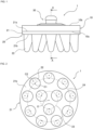
- FIG. 1 is a front view of a biological electrode 1 according to an embodiment of the present invention
- FIG. 2 is a bottom view of the biological electrode 1
- FIG. 3 is a cross-sectional view taken along the line A-A of FIG. 1
- the biological electrode 1 according to the embodiment includes a support member 10, an electrode member 20 made of a conductive rubber supported by the support member 10, and a connector 30 that electrically connects the electrode member 20 to the outside.
- the electrode member 20 includes a supported portion 21 supported by the support member 10, and a plurality of electrode portions 22 protruding from the supported portion 21 to the opposite side of the support member 10.
- the biological electrode 1 allows the biological signal of a subject to be detected (extracted) via the connector 30 by contacting the distal end portion of the plurality of electrode portions 22 of the electrode member 20 with a body (skin) of a subject.
- the biological electrode 1 is used, for example, as a biological electrode for measuring electroencephalogram.
- the biological electrode 1 is attached to the head of the subject such that the distal end side portion of the plurality of electrode portions 22 contacts the scalp of the subject.
- the biological electrode 1 may also be used to detect biological signals other than electroencephalogram.
- the support member 10 is formed of an electrically insulating material (e.g., silicone rubber).
- the support member 10 is formed in a disk shape.
- the support member 10 includes a support surface 10a for supporting the electrode member 20, and a rear surface 10b opposite to the support surface 10a.
- a through hole 10c which penetrates the support member 10 in the thickness direction (i.e., which penetrates from the support surface 10a to the rear surface 10b) is formed (see FIG. 3 ).
- the support member 10 may have a configuration corresponding to the support surface 10a, the rear surface 10b, and the through hole 10c, and does not necessarily have to be formed in a disk shape.
- the electrode member 20 is formed of a conductive rubber, and has a supported portion 21 supported by the support member 10, and a plurality of electrode portions 22 protruding from the supported portion 21 on the opposite side to the support member 10, as described above.
- the conductive rubber is a so-called conductive silicone rubber containing silicone rubber and metal particles.
- the silicone rubber is, for example, a room temperature-curable liquid silicone rubber
- the metal particles are, for example, silver particles.
- a room temperature-curable liquid silicone rubber is a silicone rubber which is in a liquid state or a paste state before curing, and which undergoes a curing reaction at 20°C to 100°C to become a rubber elastic body.
- the silver particles may include aggregated particles (aggregates) in a state in which a plurality of silver particles (primary particles) are stuck or flaked silver particles.
- the conductive rubber forming the electrode member 20 may contain other metallic particles and carbon-based material particles (such as carbon black and carbon nanotubes) having conductivity instead of silver particles, and may contain reinforcing materials, fillers, and various additives as appropriate.
- carbon-based material particles such as carbon black and carbon nanotubes
- the supported portion 21 of the electrode member 20 has the same shape as that of the support member 10. That is, in the present embodiment, the supported portion 21 is formed in a disk shape.
- the supported portion 21 has a supported surface 21a supported by the support surface 10a of the support member 10, and an electrode portion forming surface 21b on the opposite side to the supported surface 21a.
- a plurality of electrode portions 22 are protrusively formed on the electrode portion forming surface 21b of the supported portion 21.
- the plurality of electrode portions 22 are arranged concentrically on the electrode portion forming surface 21b.
- each of the plurality of electrode portions 22 is arranged so as to be positioned on the circumference of two virtual concentric circles (hereinafter, simply referred to as "concentric circles") 23 and 24 on the electrode portion forming surface 21b.
- each of the plurality of electrode portions 22 is formed so that a cross-sectional area thereof gradually decreases from a proximal end portion (base portion) thereof toward a distal end portion thereof, in other words, as the distance from the electrode portion forming surface 21b.
- each of the plurality of electrode portions 22 has a circular cross section, and gradually decreases in diameter from the proximal end portion toward the distal end portion.
- the center C1 of the cross section of each of the proximal end portions of the plurality of electrode portions 22 is arranged so as to be positioned on the circumference of any of the concentric circles 23 and 24 (It does not have to be strictly positioned on the circumferences, and it may be positioned approximately on the circumference).
- Each distal end portion of the plurality of electrode portions 22 is formed in a hemispherical shape.
- each of the plurality of electrode portions 22 is formed so that the center C2 of the distal end portion (also referred to as the center of the cross section of the distal end portion) is positioned radially outward of the center C1 of the cross section of the proximal end portion, when viewed from the arrangement center O of the plurality of electrode portions 22 (i.e., the center of the concentric circles 23 and 24). That is, each of the plurality of electrode portions 22 has an oblique conical shape with a rounded apex.
- reference numeral OL in FIG. 3 is a center line of the concentric circles 23 and 24, and shows a perpendicular line of the electrode portion forming surface 21b passing through the arrangement center O.
- the plurality of electrode portions 22 are arranged at equal intervals in the circumferential direction (It does not have to be strictly an equal interval, and it may be approximately an equal interval). Specifically, each of the plurality of electrode portions 22 is arranged at equal intervals on the circumference of any of the concentric circles 23 and 24.
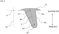
- FIG. 4 is a longitudinal section view (an enlarged view) of the electrode portion 22 cut in a plane including a perpendicular line OL of the electrode portion forming surface 21b passing through the arrangement center O (i.e., the center line of the concentric circles 23 and 24). As shown in FIG.
- the virtual straight line X connecting the center C1 of the cross section of the proximal end portion and the center C2 of the cross section of the distal end portion is inclined in such a manner that the virtual straight line X is further away from the perpendicular line OL of the electrode portion forming surface 21b passing through the arrangement center O (the center line of the concentric circles 23 and 24), toward the distal end portion from the proximal end portion.
- the generating line B1 at a position farthest from the arrangement center O is perpendicular to the electrode portion forming surface 21b.
- the generating line B2 at a position closest to the arrangement center O of the plurality of electrode portions 22 is inclined in such a manner that the generating line B2 is further away from the perpendicular line OL of the electrode portion forming surface 21b passing through the arrangement center O, toward the distal end portion from the proximal end portion.
- the term "vertical" in this specification does not mean vertical in a strict sense, and an inclination of about ⁇ 3 degrees is acceptable.
- the connector 30 is formed as a snap button type connector. More specifically, the connector 30 is formed as a male side connector in the snap button type connector. In this embodiment, the connector 30 includes a first conductive member 40 and a second conductive member 50 fitted to each other (see FIG. 3 ).
- the first conductive member 40 and the second conductive member 50 are formed of stainless steel, for example.
- one end side is embedded in the supported portion 21 of the electrode member 20 and extends through the support member 10, and the other end side protrudes from the rear surface 10b of the support member 10.
- the second conductive member 50 is disposed on the rear surface 10b of the support member 10, in a state of being fitted to the other end side of the first conductive member 40.
- the electrode member 20 of the biological electrode 1 is electrically connected to the outside by mounting (fitting) the female side connector (not shown) of the snap button type connector to the second conductive member 50. That is, the connector 30 is configured such that a part thereof is embedded in the supported portion 21 of the electrode member 20 and extends through the support member 10 to have a connecting portion to the outside which is positioned on a rear surface 10b of the support member 10.
- the electrode member 20 of the biological electrode 1 is electrically connected to a measuring device by mounting (fitting) a female side connector attached to the distal end of a lead wire of the measuring device to the second conductive member 50.
- the measuring device is a device for inputting a biological signal detected by the plurality of electrode portions 22 of the electrode member 20 of the biological electrode 1, and processing, displaying, and/or analyzing the inputted biological signal, and is not particularly limited, but may be, for example, an electroencephalogram measuring device, a wearable information device, and a health monitoring device.
- the first conductive member 40 and the second conductive member 50 will be specifically described with reference to FIG. 3 .
- the first conductive member 40 and the second conductive member 50 are formed in a flanged bottomed cylindrical shape.
- the first conductive member 40 includes a first bottomed cylindrical portion 41 having an open end 41a at one end and a closed end (bottom) 41b at the other end, and a first flange portion 42 extending radially outward from the open end 41a of the first bottomed cylindrical portion 41.
- the outer diameter of the first bottomed cylindrical portion 41 is set to substantially the same as the diameter of the through hole 10c of the support member 10.
- a fitting portion 43 recessed in the radial direction is formed in a portion near the closed end 41b on the outer peripheral surface of the first bottomed cylindrical portion 41.
- the first flange portion 42 is slightly inclined so that the outer side in the radial direction is positioned closer to the closed end 41b of the first bottomed cylindrical portion 41 than the inner side.
- the first conductive member 40 mainly the surface 42a opposite to the first bottomed cylindrical portion 41 side of the first flange portion 42 is embedded in the supported portion 21 of the electrode member 20, the first bottomed cylindrical portion 41 is inserted into the through hole 10c of the support member 10 (i.e., extends through the support member 10), and a portion in the closed end 41b side of the first bottomed cylindrical portion 41 (including the fitting portion 43) protrudes from the rear surface 10b of the support member 10.
- the surface 42a opposite to the first bottomed cylindrical portion 41 side of the first flange portion 42 is referred to as "embedded surface".
- the second conductive member 50 includes a second bottomed cylindrical portion 51 having an open end 51a at one end and a closed end (bottom) 51b at the other end, and a second flange portion 52 extending radially outward from the open end 51a of the second bottomed cylindrical portion 51.
- the second bottomed cylindrical portion 51 is formed so as to increase the inner diameter toward the closed end 51b from the open end 51a.
- the inner diameter of the open end 51a of the second bottomed cylindrical portion 51 is set to substantially the same as the outer diameter of the fitting portion 43 formed on the outer peripheral surface of the first bottomed cylindrical portion 41 of the first conductive member 40.
- the side surface and the bottom surface of the second bottomed cylindrical portion 51 are connected with a smooth curved surface.
- the second flange portion 52 has an inclined portion inclined so that the outer side in the radial direction is away from the closed end 51b of the second bottomed cylindrical portion 51 than the inner side.
- the open end 51a of the second bottomed cylindrical portion 51 is fitted and fixed to the fitting portion 43 of the first bottomed cylindrical portion 41 of the first conductive member 40, by caulking and the like, thereby, the connector 30 of the biological electrode 1 is formed.
- the connector 30 is attached to the support member 10 in advance. Specifically, it is assumed that the first bottomed cylindrical portion 41 of the first conductive member 40 is inserted into the through hole 10c of the support member 10 from the closed end 41b side, the open end 51a of the second bottomed cylindrical portion 51 of the second conductive member 50 is fitted to the fitting portion 43 of the first bottomed cylindrical portion 41 of the first conductive member 40 protruding from the rear surface 10b of the support member 10, thereby, the assembly of the support member 10 and the connector 30 is formed in advance. That is, in the present embodiment, the connector 30 is a member provided on the support member 10 side.
- a conductive rubber which is in a liquid state of a paste state and contains silicone rubber and metal particles is stirred, and the stirred conductive rubber is injected into a molding die (cavity) having a shape of the electrode member 20.
- the conductive rubber is formed in the shape of the electrode member 20 in the molding die.
- the support member 10 to which the connector 30 is attached that is, the assembly of the support member 10 and the connector 30 is placed on the conductive rubber in the molding die with the support surface 10a of the support member 10 facing downward.
- the support surface 10a of the support member 10 is placed on a portion corresponding to the supported surface 21a of the supported portion 21 of the conductive rubber formed in the shape of the electrode member 20.
- the embedded surface 42a of the first flange portion 42 of the first conductive member 40 is embedded in a portion corresponding to the supported portion 21 of the conductive rubber formed in the shape of the electrode member 20.
- the conductive rubbers molded in the form of electrode member 20 are crosslinked, with the assembly of the support member 10 and the connector 30 placed thereon.
- the conductive rubber formed in the shape of the electrode member 20 is cured, and the first conductive member 40 and electrode member 20 are integrated. That is, the connector 30 and (the supported portion 21 of) the electrode member 20 are molded integrally.
- the support member 10, the electrode member 20 and the connector 30 are integrated. Thereafter, the integrated support member 10, electrode member 20 and connector 30 are removed from the molding die (demolded) and post-processed as required to complete the biological electrode 1.
- the biological electrode 1 includes an electrode member 20 made of a conductive rubber having a plurality of electrode portions 22 in contact with a body of a subject.
- the plurality of electrode portions 22 are protrusively formed on an electrode portion forming surface 21b of the supported portion 21 of the electrode member 20 and arranged concentrically on the electrode portion forming surface 21b.
- each of the plurality of electrode portions 22 is formed so that a cross-sectional area thereof gradually decreases from a proximal end portion (base portion) thereof toward a distal end portion thereof and a center C2 of a cross section of the distal end portion is positioned radially outward of a center C1 of a cross section of the proximal end portion as viewed from an arrangement center O of the plurality of electrode portions 22.
- the virtual straight line X connecting the center C1 of the cross section of the proximal end portion and the center C2 of the cross section of the distal end portion is inclined in such a manner that the virtual straight line X is further away from the perpendicular line OL of the electrode portion forming surface 21b passing through the arrangement center O, toward the distal end portion from the proximal end portion.
- each electrode portion 22 can be a shape that can be difficult to bend (fall) in the direction opposite to the direction in which each electrode portion 22 extends (also referred to as inward, here refers to the direction toward the arrangement center O of the plurality of electrode portions 22).
- the shape of each electrode portion 22 can be a shape that hardly affected by the load input to the distal end side from the outer diagonal direction (see broken line arrow in FIG. 4 ) and have increased rigidity to the load.
- each electrode portion 22 is bent in the direction opposite to the direction in which it extends, stable contact of the plurality of electrode portions 22 with respect to the body of the subject can be maintained.
- the plurality of electrode portions 22 are arranged at equal intervals on the circumferential direction. Therefore, when a pressing force is applied to the biological electrode 1, it is suppressed that the stress is biased to act on some of the electrode portions 22. Therefore, it can be also suppressed that some of the electrode portions 22 are deformed to a greater extent than the remaining electrode portions 22 and cannot be stably contacted with the body of the subject.
- Each of the plurality of electrode portions 22 has an oblique conical shape with a rounded apex. Therefore, it can be effectively suppressed that each electrode portions 22 is bent in the direction opposite to the direction in which it extends, and the distal end side portion of the plurality of electrode portions 22 can be stably contacted with the body of the subject with little discomfort to the subject.
- each of the plurality of electrode portions 22 the generating line B1 at a position farthest from the arrangement center O of the plurality of electrode portions 22 is perpendicular to the electrode portion forming surface 21b (as described above, an inclination of about ⁇ 3 degrees is acceptable). Therefore, while preventing a decrease in workability at the time of demolding by suppressing the generation of the undercut portion, the shape of each electrode portion 22 can be a shape which is hardly affected by the load input to the distal end side from the outer oblique direction and increases the rigidity to the load input from the outer oblique direction.
- the plurality of electrode portions 22 are arranged concentrically on the electrode portion forming surface 21b.
- the present invention is not limited thereto.
- the plurality of electrode portions 22 may be arranged circularly.
- each of the plurality of electrode portions 22 is arranged so as to be positioned on the circumference of the virtual circle 25 on the electrode portion forming surface 21b.
- reference numeral O indicates the arrangement center of the plurality of electrode portions 22 (the center of the virtual circle 25)
- reference numeral OL indicates the perpendicular line of the electrode portion forming surface 21b passing through the arrangement center O (the center line of the virtual circle 25).
- each of the plurality of electrode portions 22 is arranged so as to be positioned on the circumference of two virtual concentric circles 23 and 24 on the electrode portion forming surface 21b of the supported portion 21 of the electrode member 20.
- the present invention is not limited thereto.
- Each of the plurality of electrode portions 22 may be arranged so as to be positioned on the circumference of three or more virtual concentric circles.
- the biological electrode 1 may have an additional electrode portion of any shape which is brought into contact with the body of the subject in addition to the plurality of electrode portions 22 as needed.
- each of the plurality of electrode portions 22 has a circular cross section.
- the present invention is not limited thereto.
- each of the plurality of electrode portions 22 may have a cross-section of a shape other than circular (e.g., a rounded corner polygon).
- each of the plurality of electrode portions 22 has an oblique conical shape with a rounded apex.
- the generating line B1 at a position farthest from the arrangement center O of the plurality of electrode portions 22 is perpendicular to the electrode portion forming surface 21b.
- the center C2 of the cross section of the distal end portion is located radially outward of the center C1 of the cross section of the proximal end portion as viewed from the arrangement center O.
Landscapes
- Life Sciences & Earth Sciences (AREA)
- Health & Medical Sciences (AREA)
- Medical Informatics (AREA)
- Biophysics (AREA)
- Pathology (AREA)
- Engineering & Computer Science (AREA)
- Biomedical Technology (AREA)
- Heart & Thoracic Surgery (AREA)
- Physics & Mathematics (AREA)
- Molecular Biology (AREA)
- Surgery (AREA)
- Animal Behavior & Ethology (AREA)
- General Health & Medical Sciences (AREA)
- Public Health (AREA)
- Veterinary Medicine (AREA)
- Measurement And Recording Of Electrical Phenomena And Electrical Characteristics Of The Living Body (AREA)
Claims (4)
- Biologische Elektrode (1), die ein Elektrodenelement (20) aufweist, das aus einem leitfähigen Gummi hergestellt ist und mehrere Elektrodenabschnitte (22) aufweist, die dazu dienen, in Kontakt mit einem Körper einer Person gebracht zu werden, wobeidie mehreren Elektrodenabschnitte (22) auf einer Elektrodenabschnitt-Bildungsfläche (21b) des Elektrodenelements (20) vorstehend ausgebildet und kreisförmig oder konzentrisch auf der Elektrodenabschnitt-Bildungsfläche (21b) angeordnet sind, undjeder der mehreren Elektrodenabschnitte (22) eine schräge konische Form mit einem abgerundeten Scheitelpunkt aufweist und so ausgebildet ist, dass eine Querschnittsfläche davon von einem proximalen Endabschnitt davon zu einem distalen Endabschnitt davon allmählich abnimmt und eine Mitte (C2) eines Querschnitts des distalen Endabschnitts von einer Anordnungsmitte (O) der mehreren Elektrodenabschnitte (22) gesehen radial außerhalb einer Mitte (C1) eines Querschnitts des proximalen Endabschnitts positioniert ist,wobeiin jedem der mehreren Elektrodenabschnitte (22) eine Erzeugungslinie (B1) an einer Position, die am weitesten von dem Anordnungszentrum (O) entfernt ist, senkrecht zu der Elektrodenabschnitt-Bildungsfläche (21b) verläuft.
- Biologische Elektrode (1) nach Anspruch 1, wobei
in jedem der mehreren Elektrodenabschnitte (22) eine virtuelle gerade Linie (X), die die Mitte (C1) des Querschnitts des proximalen Endabschnitts und die Mitte (C2) des Querschnitts des distalen Endabschnitts verbindet, derart geneigt ist, dass die virtuelle gerade Linie (X) von einer senkrechten Linie (OL) der Elektrodenabschnitt-Bildungsfläche (21b), die durch das Anordnungszentrum (O) verläuft, zum distalen Endabschnitt vom proximalen Endabschnitt weiter entfernt ist. - Biologische Elektrode (1) nach Anspruch 1 oder 2, wobei
jeder der mehreren Elektrodenabschnitte (22) so angeordnet ist, dass er auf einem Umfang eines virtuellen Kreises (25) oder mehrerer virtueller konzentrischer Kreise (23, 24) auf der Elektrodenabschnitt-Bildungsfläche (21b) positioniert ist. - Biologische Elektrode (1) nach einem der Ansprüche 1 bis 3, die ferner aufweist:ein Trägerelement (10), undeinen Verbinder (30),wobeidas Elektrodenelement (20) einen getragenen Abschnitt (21) aufweist, der von dem Trägerelement (10) getragen wird, und die mehreren Elektrodenabschnitte (22) so vorgesehen sind, dass sie von dem getragenen Abschnitt (21) auf der dem Trägerelement (10) gegenüberliegenden Seite vorstehen,der Verbinder (30) konfiguriert ist, das Elektrodenelement (20) elektrisch mit der Außenseite zu verbinden, und so konfiguriert ist, dass ein Teil davon in dem getragenen Abschnitt (21) des Elektrodenelements (20) eingebettet ist und sich durch das Trägerelement (10) erstreckt, so dass er einen Verbindungsabschnitt zur Außenseite aufweist, der auf einer Oberfläche des Trägerelements (10) auf der dem Elektrodenelement (20) gegenüberliegenden Seite positioniert ist, und die Elektrodenabschnitt-Bildungsfläche (21b) aus dem getragenen Abschnitt (21) besteht.
Applications Claiming Priority (2)
| Application Number | Priority Date | Filing Date | Title |
|---|---|---|---|
| JP2020019690 | 2020-02-07 | ||
| PCT/JP2021/000648 WO2021157287A1 (ja) | 2020-02-07 | 2021-01-12 | 生体電極 |
Publications (4)
| Publication Number | Publication Date |
|---|---|
| EP4101382A1 EP4101382A1 (de) | 2022-12-14 |
| EP4101382A4 EP4101382A4 (de) | 2024-03-13 |
| EP4101382C0 EP4101382C0 (de) | 2025-02-19 |
| EP4101382B1 true EP4101382B1 (de) | 2025-02-19 |
Family
ID=77200507
Family Applications (1)
| Application Number | Title | Priority Date | Filing Date |
|---|---|---|---|
| EP21751301.9A Active EP4101382B1 (de) | 2020-02-07 | 2021-01-12 | Bioelektrode |
Country Status (5)
| Country | Link |
|---|---|
| US (1) | US12446815B2 (de) |
| EP (1) | EP4101382B1 (de) |
| JP (1) | JP7395624B2 (de) |
| CN (1) | CN114901144B (de) |
| WO (1) | WO2021157287A1 (de) |
Families Citing this family (3)
| Publication number | Priority date | Publication date | Assignee | Title |
|---|---|---|---|---|
| JP7767288B2 (ja) | 2019-12-23 | 2025-11-11 | アリメトリー リミテッド | 電極パッチおよび接続システム |
| US20240422467A1 (en) * | 2021-12-28 | 2024-12-19 | Sony Semiconductor Solutions Corporation | Electronic device |
| WO2024029446A1 (ja) * | 2022-08-04 | 2024-02-08 | Nok株式会社 | 生体用電極 |
Family Cites Families (20)
| Publication number | Priority date | Publication date | Assignee | Title |
|---|---|---|---|---|
| CN101716073B (zh) * | 2009-12-09 | 2011-07-20 | 中国科学院半导体研究所 | 长期记录生理电信号的侵入式斜针无痛皮肤干电极器件 |
| JP5561122B2 (ja) * | 2010-11-25 | 2014-07-30 | ソニー株式会社 | 生体信号検出装置 |
| CN102499674B (zh) * | 2011-10-15 | 2014-01-29 | 杭州电子科技大学 | 一种采用插座结构的多重保障触点紧密接触头皮的脑电帽 |
| US20150238100A1 (en) * | 2014-02-27 | 2015-08-27 | National Chiao Tung University | Sensor electrode device |
| CN104068852A (zh) * | 2014-06-28 | 2014-10-01 | 苏州格林泰克科技有限公司 | 一种生物电信号传感器 |
| CN104287727A (zh) * | 2014-09-28 | 2015-01-21 | 青岛柏恩鸿泰电子科技有限公司 | 弹性干式软电极 |
| WO2016080804A1 (en) * | 2014-11-20 | 2016-05-26 | Samsung Electronics Co., Ltd. | Apparatus for measuring bioelectrical signals |
| KR102361026B1 (ko) * | 2014-11-20 | 2022-02-08 | 삼성전자주식회사 | 생체신호 측정 장치 |
| JP2017074370A (ja) * | 2015-10-13 | 2017-04-20 | ニッタ株式会社 | 脳波測定用電極 |
| JP2017108763A (ja) * | 2015-12-14 | 2017-06-22 | セイコーエプソン株式会社 | 電極針、生体情報測定装置、及び液体供給装置 |
| CN110225712A (zh) * | 2016-12-15 | 2019-09-10 | 英诺斯菲尔科技工程有限公司 | 刷电极 |
| US11058337B2 (en) * | 2017-02-03 | 2021-07-13 | International Business Machines Corporation | Flexible silicon nanowire electrode |
| JP6927632B2 (ja) * | 2017-04-11 | 2021-09-01 | ニッタ株式会社 | 脳波測定用電極 |
| JPWO2018230445A1 (ja) | 2017-06-16 | 2020-05-21 | Nok株式会社 | 生体電極 |
| US20190150838A1 (en) * | 2017-07-17 | 2019-05-23 | Devon Greco | Method and apparatus for measurement and visual feedback of physiologic signals through headworn device |
| WO2019094609A1 (en) * | 2017-11-09 | 2019-05-16 | Cognionics, Inc. | Low noise solid biopotential electrode |
| WO2019130832A1 (ja) * | 2017-12-27 | 2019-07-04 | アルプスアルパイン株式会社 | 生体情報測定用電極および生体情報測定用電極の製造方法 |
| JP6968719B2 (ja) * | 2018-01-26 | 2021-11-17 | Nok株式会社 | 脳波検出用生体電極 |
| JP6975082B2 (ja) * | 2018-03-23 | 2021-12-01 | アルプスアルパイン株式会社 | 生体情報測定用電極 |
| CN109124626B (zh) * | 2018-07-26 | 2021-11-23 | 天津大学 | 新型无源柔性光学电极 |
-
2021
- 2021-01-12 EP EP21751301.9A patent/EP4101382B1/de active Active
- 2021-01-12 CN CN202180007769.4A patent/CN114901144B/zh active Active
- 2021-01-12 US US17/796,944 patent/US12446815B2/en active Active
- 2021-01-12 JP JP2021575675A patent/JP7395624B2/ja active Active
- 2021-01-12 WO PCT/JP2021/000648 patent/WO2021157287A1/ja not_active Ceased
Also Published As
| Publication number | Publication date |
|---|---|
| JP7395624B2 (ja) | 2023-12-11 |
| EP4101382C0 (de) | 2025-02-19 |
| US20230069007A1 (en) | 2023-03-02 |
| JPWO2021157287A1 (de) | 2021-08-12 |
| EP4101382A4 (de) | 2024-03-13 |
| CN114901144B (zh) | 2025-09-05 |
| EP4101382A1 (de) | 2022-12-14 |
| US12446815B2 (en) | 2025-10-21 |
| WO2021157287A1 (ja) | 2021-08-12 |
| CN114901144A (zh) | 2022-08-12 |
Similar Documents
| Publication | Publication Date | Title |
|---|---|---|
| US12446815B2 (en) | Biological electrode | |
| CN111064029B (zh) | 具有片层篮的连接插头和插座 | |
| US8382531B2 (en) | Electrical connector assembly | |
| US9362631B2 (en) | Shield sleeve having a sleeve member with a protruding contact finger | |
| US8944827B2 (en) | Coaxial electrical connector and coaxial electrical connector device | |
| CN102160786A (zh) | 扣式电极与导联线的连接结构 | |
| JP6840700B2 (ja) | シールされた電気コネクタアセンブリおよびワイヤシール | |
| EP4208095B1 (de) | Weiche und trockene elektrode | |
| CN104335426A (zh) | 插座端子 | |
| JP2019097733A (ja) | 脳活動計測用電極、その電極を使用した頭部装着装置及び脳活動計測システム | |
| EP4295770B1 (de) | Bioelektrode | |
| JP6186522B2 (ja) | 接触力のレンジ及び方向の情報をフィードバックする血管内介入触覚プローブ | |
| CN111163691A (zh) | 脑电波检测用生物电极 | |
| US20260041352A1 (en) | Electrode member and bioelectric signal measuring electrode | |
| CN219499795U (zh) | 导线固定结构 | |
| KR100855247B1 (ko) | 생체용 전극 및 이를 포함하는 생체신호 측정장치 | |
| WO2024101106A1 (ja) | 生体用電極 | |
| JP7456230B2 (ja) | 生体用電極 | |
| JP7826491B2 (ja) | 生体用電極 | |
| WO2019181389A1 (ja) | 生体情報測定用電極 | |
| US20210338129A1 (en) | Bioelectrode and manufacturing method of bioelectrode | |
| HK1157607A (en) | Connecting structure of snap electrode and electric wire |
Legal Events
| Date | Code | Title | Description |
|---|---|---|---|
| STAA | Information on the status of an ep patent application or granted ep patent |
Free format text: STATUS: THE INTERNATIONAL PUBLICATION HAS BEEN MADE |
|
| PUAI | Public reference made under article 153(3) epc to a published international application that has entered the european phase |
Free format text: ORIGINAL CODE: 0009012 |
|
| STAA | Information on the status of an ep patent application or granted ep patent |
Free format text: STATUS: REQUEST FOR EXAMINATION WAS MADE |
|
| 17P | Request for examination filed |
Effective date: 20220527 |
|
| AK | Designated contracting states |
Kind code of ref document: A1 Designated state(s): AL AT BE BG CH CY CZ DE DK EE ES FI FR GB GR HR HU IE IS IT LI LT LU LV MC MK MT NL NO PL PT RO RS SE SI SK SM TR |
|
| DAV | Request for validation of the european patent (deleted) | ||
| DAX | Request for extension of the european patent (deleted) | ||
| A4 | Supplementary search report drawn up and despatched |
Effective date: 20240213 |
|
| RIC1 | Information provided on ipc code assigned before grant |
Ipc: A61B 5/291 20210101ALI20240207BHEP Ipc: A61B 5/266 20210101ALI20240207BHEP Ipc: A61B 5/271 20210101ALI20240207BHEP Ipc: A61B 5/25 20210101AFI20240207BHEP |
|
| GRAP | Despatch of communication of intention to grant a patent |
Free format text: ORIGINAL CODE: EPIDOSNIGR1 |
|
| STAA | Information on the status of an ep patent application or granted ep patent |
Free format text: STATUS: GRANT OF PATENT IS INTENDED |
|
| GRAS | Grant fee paid |
Free format text: ORIGINAL CODE: EPIDOSNIGR3 |
|
| RIC1 | Information provided on ipc code assigned before grant |
Ipc: A61B 5/291 20210101ALI20241115BHEP Ipc: A61B 5/266 20210101ALI20241115BHEP Ipc: A61B 5/271 20210101ALI20241115BHEP Ipc: A61B 5/25 20210101AFI20241115BHEP |
|
| INTG | Intention to grant announced |
Effective date: 20241203 |
|
| GRAA | (expected) grant |
Free format text: ORIGINAL CODE: 0009210 |
|
| STAA | Information on the status of an ep patent application or granted ep patent |
Free format text: STATUS: THE PATENT HAS BEEN GRANTED |
|
| AK | Designated contracting states |
Kind code of ref document: B1 Designated state(s): AL AT BE BG CH CY CZ DE DK EE ES FI FR GB GR HR HU IE IS IT LI LT LU LV MC MK MT NL NO PL PT RO RS SE SI SK SM TR |
|
| REG | Reference to a national code |
Ref country code: GB Ref legal event code: FG4D |
|
| REG | Reference to a national code |
Ref country code: CH Ref legal event code: EP |
|
| REG | Reference to a national code |
Ref country code: IE Ref legal event code: FG4D |
|
| REG | Reference to a national code |
Ref country code: DE Ref legal event code: R096 Ref document number: 602021026407 Country of ref document: DE |
|
| U01 | Request for unitary effect filed |
Effective date: 20250314 |
|
| U07 | Unitary effect registered |
Designated state(s): AT BE BG DE DK EE FI FR IT LT LU LV MT NL PT RO SE SI Effective date: 20250321 |
|
| PG25 | Lapsed in a contracting state [announced via postgrant information from national office to epo] |
Ref country code: RS Free format text: LAPSE BECAUSE OF FAILURE TO SUBMIT A TRANSLATION OF THE DESCRIPTION OR TO PAY THE FEE WITHIN THE PRESCRIBED TIME-LIMIT Effective date: 20250519 |
|
| PG25 | Lapsed in a contracting state [announced via postgrant information from national office to epo] |
Ref country code: PL Free format text: LAPSE BECAUSE OF FAILURE TO SUBMIT A TRANSLATION OF THE DESCRIPTION OR TO PAY THE FEE WITHIN THE PRESCRIBED TIME-LIMIT Effective date: 20250219 |
|
| PG25 | Lapsed in a contracting state [announced via postgrant information from national office to epo] |
Ref country code: ES Free format text: LAPSE BECAUSE OF FAILURE TO SUBMIT A TRANSLATION OF THE DESCRIPTION OR TO PAY THE FEE WITHIN THE PRESCRIBED TIME-LIMIT Effective date: 20250219 |
|
| PG25 | Lapsed in a contracting state [announced via postgrant information from national office to epo] |
Ref country code: NO Free format text: LAPSE BECAUSE OF FAILURE TO SUBMIT A TRANSLATION OF THE DESCRIPTION OR TO PAY THE FEE WITHIN THE PRESCRIBED TIME-LIMIT Effective date: 20250519 Ref country code: IS Free format text: LAPSE BECAUSE OF FAILURE TO SUBMIT A TRANSLATION OF THE DESCRIPTION OR TO PAY THE FEE WITHIN THE PRESCRIBED TIME-LIMIT Effective date: 20250619 |
|
| PG25 | Lapsed in a contracting state [announced via postgrant information from national office to epo] |
Ref country code: HR Free format text: LAPSE BECAUSE OF FAILURE TO SUBMIT A TRANSLATION OF THE DESCRIPTION OR TO PAY THE FEE WITHIN THE PRESCRIBED TIME-LIMIT Effective date: 20250219 |
|
| PG25 | Lapsed in a contracting state [announced via postgrant information from national office to epo] |
Ref country code: GR Free format text: LAPSE BECAUSE OF FAILURE TO SUBMIT A TRANSLATION OF THE DESCRIPTION OR TO PAY THE FEE WITHIN THE PRESCRIBED TIME-LIMIT Effective date: 20250520 |
|
| PG25 | Lapsed in a contracting state [announced via postgrant information from national office to epo] |
Ref country code: SM Free format text: LAPSE BECAUSE OF FAILURE TO SUBMIT A TRANSLATION OF THE DESCRIPTION OR TO PAY THE FEE WITHIN THE PRESCRIBED TIME-LIMIT Effective date: 20250219 |
|
| PG25 | Lapsed in a contracting state [announced via postgrant information from national office to epo] |
Ref country code: CZ Free format text: LAPSE BECAUSE OF FAILURE TO SUBMIT A TRANSLATION OF THE DESCRIPTION OR TO PAY THE FEE WITHIN THE PRESCRIBED TIME-LIMIT Effective date: 20250219 |
|
| PG25 | Lapsed in a contracting state [announced via postgrant information from national office to epo] |
Ref country code: SK Free format text: LAPSE BECAUSE OF FAILURE TO SUBMIT A TRANSLATION OF THE DESCRIPTION OR TO PAY THE FEE WITHIN THE PRESCRIBED TIME-LIMIT Effective date: 20250219 |
|
| PLBE | No opposition filed within time limit |
Free format text: ORIGINAL CODE: 0009261 |
|
| STAA | Information on the status of an ep patent application or granted ep patent |
Free format text: STATUS: NO OPPOSITION FILED WITHIN TIME LIMIT |
|
| PGFP | Annual fee paid to national office [announced via postgrant information from national office to epo] |
Ref country code: GB Payment date: 20251127 Year of fee payment: 6 |
|
| U20 | Renewal fee for the european patent with unitary effect paid |
Year of fee payment: 6 Effective date: 20251205 |
|
| 26N | No opposition filed |
Effective date: 20251120 |